

Page 1

User Manual系统安装
系统安装系统安装
系统安装手册
手册手册
手册
QSSC-980 Server服务器
服务器服务器
服务器
Page 2

Page 3
Preface
i
Regional EMC Compliance Information
FCC Verification Notice (USA only)
This device complies with Part 15 of the FCC Rules. Operation is subject to the following two conditions:
(1) this device may not cause harmful interference, and
(2) this device must accept any interference received, including interference that may cause undesired operation.
Class A
This equipment has been tested and found to comply with the limits for a Class A digital device pursuant
to Part 15 of the FCC Rules. These limits are designed to provide reasonable protection against harmful
interference when the equipment is operated in a commercial environment.
This equipment generates, uses, and can radiate radio frequency energy and, if not installed and used in
accordance with the manufacturer’s instruction manual, may cause harmful interference with radio communications.
Operation of this equipment in a residential area is likely to cause harmful interference, in which case you will be
required to correct the interference at your own expense.
INDUSTRY CANADA (Canada only)
This Class B (or Class A, if so indicated on the registration label) digital apparatus meets the requirements of the
Canadian Interference-Causing Equipment Regulations.
Cet appareil numérique de la Classe B (ou Classe A, si ainsi indiqué sur l’étiquette d’enregistration) respecte
toutes les exigences du Reglement sur le Materiel Brouilleur du Canada.
CE Declaration of Conformity (EUROPE only)
This product has been tested in accordance to, and complies with the European Low Voltage Directive
(73/23/EEC) and European EMC Directive (89/336/EEC).
The product has been marked with the CE Mark to illustrate its compliance.
VCCI (Japan only)
English translation of the notice above is as follow:
This is a Class A product based on the standard of the Voluntary Control Council for Interference (VCCI) for
information technology equipment. If this equipment is used in a domestic environment, radio disturbance may
arise. When such trouble occurs, the user may be required to take corrective actions.
CCC (China only)
The following CCC EMC Warning is marked on the product: EMC Warning are required for Class A
products.
此为 A 级产品,在生活环境中,该产品可能会造成无线电干扰,在这种情况下,可能需要用户对其干
扰采取可行的措施.
Page 4
Preface
ii
China RoHS Declaration Table
有毒有害物质或元素
有毒有害物质或元素有毒有害物质或元素
有毒有害物质或元素 (Hazardous Substance)
部件名称
部件名称部件名称
部件名称
(Component Name)
铅铅铅铅
(Pb)
汞汞汞汞
(Hg)
镉镉镉镉
(Cd)
六价铬
六价铬六价铬
六价铬
(Cr6+)
多溴联苯
多溴联苯多溴联苯
多溴联苯
(PBB)
多溴二苯醚
多溴二苯醚多溴二苯醚
多溴二苯醚
(PBDE)
机箱子组件
Chassis
Subassembly
×
○ ○ ○ ○ ○
电源
Power Supply
×
○ ○ ○ ○ ○
印刷板组件
Printed Board
Assemblies (PBA)
×
○ ○ ○ ○ ○
○:表示该有毒有害物质在该部件所有均质材料中的含量均在 SJ/T 11363-2006 标准规定的限量要求以下。
○:Indicates that this hazardous substance contained in all
homogeneous materials of this part is below the limit requirement in SJ/T
11363-2006.
BSMI (Tawain only)
×:Indicates that this hazardous substance contained in at least one of the homogeneous materials of this part is above the limit requirement in SJ/T 11363-2006.
BSMI (Tawain only)
The following BSMI EMC Warning is marked on the product: BSMI ID No and EMC Warning are required
for Class A products.
這是甲類的資訊產品,在居住的環境中使用時,可能會造成射頻干擾,在這種情況下,使用者會被要求採
取某些適當對策。
Copyright
This publication, including all photographs, illustrations and software, is protected under international copyright
laws, with all rights reserved. Neither this manual, nor any of the material contained herein, may be reproduced
without the express written consent of the manufacturer.
Version 1.0, October, 2009
Disclaimer
The information in this document is subject to change without notice. The manufacturer makes no representations
or warranties with respect to the contents hereof and specifically disclaims any implied warranties of
merchantability or fitness for any particular purpose. Furthermore, the manufacturer reserves the right to revise
this publication and to make changes from time to time in the content hereof without obligation of the manufacturer
to notify any person of such revision or changes.
Page 5

Preface
iii
警示
警示警示
警示::::安全指示說明
安全指示說明安全指示說明
安全指示說明
請務必遵守下列安全指導說明,以確保您的人身安全,避免可能對系統和工作環境造成損害。
警告
警告警告
警告:::: 您系統中的電源供應器可能會釋放出高電壓或電能
您系統中的電源供應器可能會釋放出高電壓或電能您系統中的電源供應器可能會釋放出高電壓或電能
您系統中的電源供應器可能會釋放出高電壓或電能,,,,可能會對您的身體產生危害
可能會對您的身體產生危害可能會對您的身體產生危害
可能會對您的身體產生危害。。。。除非另有指示
除非另有指示除非另有指示
除非另有指示,,,,否否否否
則僅限受過專業訓練之維修技師有權卸除機殼及拆裝任何系統內部的元件
則僅限受過專業訓練之維修技師有權卸除機殼及拆裝任何系統內部的元件則僅限受過專業訓練之維修技師有權卸除機殼及拆裝任何系統內部的元件
則僅限受過專業訓練之維修技師有權卸除機殼及拆裝任何系統內部的元件。
。。
。
警告
警告警告
警告:::: 如果電池安裝不正確
如果電池安裝不正確如果電池安裝不正確
如果電池安裝不正確,,,,會有發生爆炸的危險
會有發生爆炸的危險會有發生爆炸的危險
會有發生爆炸的危險。。。。更換電池時
更換電池時更換電池時
更換電池時,,,,請務必使用製造商建議的同等種類品牌
請務必使用製造商建議的同等種類品牌請務必使用製造商建議的同等種類品牌
請務必使用製造商建議的同等種類品牌。。。。
請參閱
請參閱請參閱
請參閱《《《《處理廢棄電池
處理廢棄電池處理廢棄電池
處理廢棄電池。
。。
。
警告
警告警告
警告:::: 本系統可能有一條以上的電源線
本系統可能有一條以上的電源線本系統可能有一條以上的電源線
本系統可能有一條以上的電源線。。。。為了降低觸電風險
為了降低觸電風險為了降低觸電風險
為了降低觸電風險,,,,專業服務技術人員必須先拔掉所有電源線
專業服務技術人員必須先拔掉所有電源線專業服務技術人員必須先拔掉所有電源線
專業服務技術人員必須先拔掉所有電源線
後才能維修系統
後才能維修系統後才能維修系統
後才能維修系統。
。。
。
安安安安全性
全性全性
全性::::一般
一般一般
一般
請仔細注意並遵守維修標示上的說明。請務必遵照系統文件載明的方式使用產品。如果外殼貼有一發光燈
泡圖樣的三角形標誌,代表打開或卸除它可能會發生觸電。建議只有專業的服務人員才能接觸這些內部元
件。
如果發生下列任何一個情況,請拔掉本產品的電源並更換損壞零件,或者是聯絡專業的服務提供者:
電源線、延長線或插頭損壞。
有東西掉進本產品內。
產品淋到水。
產品摔到或損壞。
雖有遵守操作指示,但產品無法正常運作。
請勿將產品放在靠近輻射物或太熱的地方。此外,請勿擋住產品的通風孔。
請注意不要讓食物或液體灑到系統元件上,避免在潮濕的環境中使用本產品。如果系統受潮,請參閱《安
全性:萬一系統受潮》一節中的相關說明。
請勿將任何物件硬塞入您的系統開口內。這麼做可能會造成內部元件短路,導致起火或觸電。
請務必搭配經過認可的設備使用本產品。
在卸除外殼或接觸內部元件前,請先稍待一段時間讓產品冷卻下來。
請注意,本產品連接的外部電源必須符合額定功率標誌上的載明規格。如果您不確定電源類型,請洽詢您
的服務提供者或當地的電力公司。
注意
注意注意
注意:::: 為了避免損壞您的系統
為了避免損壞您的系統為了避免損壞您的系統
為了避免損壞您的系統,,,,請務必將變壓器
請務必將變壓器請務必將變壓器
請務必將變壓器(如果有提供的話
如果有提供的話如果有提供的話
如果有提供的話) 切到最接近您當地國家的供電電壓
切到最接近您當地國家的供電電壓切到最接近您當地國家的供電電壓
切到最接近您當地國家的供電電壓。。。。此外
此外此外
此外,,,,
請確定您的顯示器和連接裝置有支援當地國家的電源功率
請確定您的顯示器和連接裝置有支援當地國家的電源功率請確定您的顯示器和連接裝置有支援當地國家的電源功率
請確定您的顯示器和連接裝置有支援當地國家的電源功率。
。。
。
請務必使用經過認證的合格電源線。如果您的系統沒有隨附電源線或專用的 AC 電源接線,請購買經過您
所在國家認證的合格電源線。電源線必須支援產品額定功率標籤上標明的電壓和電流規格。接線的電壓和
電流承載量必須大於產品上標明的電壓和電流規格。
為防觸電,請將系統和周邊設備的電源線插到有適當接地的插座中。這些接線配有三腳插頭,可確保適當
接地。請勿使用變壓整流器的插頭或者是拔掉插頭上的接地腳。如果您必須用到延長線,請使用配有適當
接地插頭的三線式接線。
Page 6

Preface
iv
請特別注意延長線及其多孔電源插座盒的功率規格。請注意,所有產品接到延長線或多孔電源插座盒的總
電流不得超過延長線或多孔電源插座盒本身電流上限的百分之八十。
為避免您的系統供電發生突波的不穩定現象,請使用穩壓器、電路調節器或不斷電電源供應器(UPS)
請小心配置系統接線和電源線;務必將接線整理妥當以免有人不慎踩到或絆倒。請確保沒有任何東西壓在
接線上。
請勿任意改造電源線或插頭。如需修改您的場地配線,請洽詢有執照的專業電匠或您當地的電力公司。請
務必遵循您當地/全國的配線法規。
為避免損壞主機板,關閉系統電源後請再等待五秒,之後再拆下系統主機板上的元件或拔除系統周邊裝
置。
處理電池時請特別小心。請勿將電池拆開、壓碎、刺穿、使其外部連接短路、丟棄到火裡或水中,或者是
使其暴露在高於攝氏 60 度(華氏 140 度) 環境下。請勿自行嘗試拆開或修復電池;務必更換產品指定使用
的電池類型。
如果您的系統有隨附熱插拔電源供應器,請特別注意下列有關接上或拔除接線的指示說明:
接上電源線前,請先裝好電源供應器。
移除電源供應器前請先拔除電源線。
如果系統有多個供電來源,請拔除所有電源供應器的電源接線來切斷系統供電。
搬動產品請格外小心;請確認所有腳輪和/或支腳有牢牢地接在系統上。請避免突然停下或在凹凸的表面
上搬運產品。
根據本產品德國工作場所法則第§2 條有關視訊顯示裝置的規定,本產品不適於搭配視訊顯示裝置使用。
安全性
安全性安全性
安全性::::萬一系統受潮
萬一系統受潮萬一系統受潮
萬一系統受潮
備註
備註備註
備註::::在開始執行下列步驟前
在開始執行下列步驟前在開始執行下列步驟前
在開始執行下列步驟前,,,,請先參閱
請先參閱請先參閱
請先參閱《《《《安全性
安全性安全性
安全性::::一般
一般一般
一般》》》》和和和和《《《《安全性
安全性安全性
安全性::::避免靜電釋放
避免靜電釋放避免靜電釋放
避免靜電釋放》》》》中的相關說明
中的相關說明中的相關說明
中的相關說明。
。。
。
請關閉系統和裝置電源,拔除它們的電源接線,並等待 10 到 20 秒後再打開系統機殼。
請讓系統自然風乾至少 24 小時。在繼續進行下列程序前,請先確認系統已完全乾燥。
除圖形卡外,請拆下安裝在系統內的所有配接卡。如果您的主要硬碟是連接到磁碟控制卡而非系統的主
機板連接器,則請勿拆下磁碟控制卡。
闔上系統機殼,重新接妥系統和裝置的電源線後開啟系統。
如果您系統的供電情況正常,請繼續執行步驟 6。如果無法正常供電,請聯絡尋求技術支援(請參見您系
統文件中載明的適當聯絡資訊)。
請關閉系統和裝置電源,拔除它們的電源接線,並等待 10 到 20 秒後再打開系統機殼。
將所有配接卡重新裝到系統中。
闔上系統機殼,重新接妥系統和裝置的電源線後開啟系統。
執行診斷程式。
如果有任何測試失敗,請聯絡尋求技術支援(請參見您系統文件中載明的適當聯絡資訊)。
如果您的系統備有 AC 整流器:
請將 AC 整流器放置在通風良好的地方,如桌面或地面上。
系統正常運作時 AC 整流器可能會發熱。於系統運作時或開始運作後調整整流器時, 請務必格外小心。
Page 7

Preface
v
安全性
安全性安全性
安全性::::架設系統機架
架設系統機架架設系統機架
架設系統機架
請仔細閱讀下列注意事項,以確保機架的穩定性和安全。另請參閱系統和機架隨附的機架安裝說明文件,閱讀其中
的特別注意聲明和安裝程序。
系統是指放在機架中的元件。因此,「元件」可以代表任何系統及各種周邊裝置,或者是支援硬體。
警告
警告警告
警告:::: 將系統安裝到機架中前
將系統安裝到機架中前將系統安裝到機架中前
將系統安裝到機架中前,,,,請先裝好獨立
請先裝好獨立請先裝好獨立
請先裝好獨立(單一
單一單一
單一) 機架的正面和側邊支腳
機架的正面和側邊支腳機架的正面和側邊支腳
機架的正面和側邊支腳,,,,或者是裝好
或者是裝好或者是裝好
或者是裝好連接機架的正面支
連接機架的正面支連接機架的正面支
連接機架的正面支
腳腳腳腳。。。。如果沒有事先裝好支腳就冒然將系統安裝到機架中
如果沒有事 先裝好支腳就冒然將系 統安裝到機架中如果沒有事 先裝好支腳就冒然將系 統安裝到機架中
如果沒有事 先裝好支腳就冒然將系 統安裝到機架中,,,,可能會導致機架傾覆
可能會導致 機架傾覆可能會導致 機架傾覆
可能會導致 機架傾覆,,,,更嚴重的話可能還會造成人員受
更嚴重的話 可能還會造成 人員受更嚴重的話 可能還會造成 人員受
更嚴重的話 可能還會造成 人員受
傷傷傷傷。。。。因此
因此因此
因此,,,,將元件安裝到機架中前請務必先裝好支腳
將元件安裝到機架中前請務必先裝好支腳將元件安裝到機架中前請務必先裝好支腳
將元件安裝到機架中前請務必先裝好支腳。。。。
將系統
將系統將系統
將系統/元件安裝到機架中後
元件安裝到機架中後元件安裝到機架中後
元件安裝到機架中後,,,,一次最多只能拉動一個滑軌裝置
一次最多只能拉動一個滑軌裝置一次最多只能拉動一個滑軌裝置
一次最多只能拉動一個滑軌裝置,,,,將單一元件拉出機架
將單一元件拉出機架將單一元件拉出機架
將單一元件拉出機架。。。。如果拉出一個以上的元件
如果拉出一個以上的元件如果拉出一個以上的元件
如果拉出一個以上的元件,,,,
其重量可能會造成機架傾覆
其重量可能會造成機架傾覆其重量可能會造成機架傾覆
其重量可能會造成機架傾覆,,,,進而導致嚴重的人身傷害
進而導致嚴重的人身傷害進而導致嚴重的人身傷害
進而導致嚴重的人身傷害。。。。
備註
備註備註
備註:::: 建議您將系統裝在使用機架套件所組裝的機櫃中
建議您將系統裝在使用機架套件所組裝的機櫃中建議您將系統裝在使用機架套件所組裝的機櫃中
建議您將系統裝在使用機架套件所組裝的機櫃中,,,,以確保您獨立裝置和機櫃元件的使用安全
以確保您獨立裝置和機櫃元件的使用安全以確保您獨立裝置和機櫃元件的使用安全
以確保您獨立裝置和機櫃元件的使用安全。。。。如果您將系統
如果您將系統如果您將系統
如果您將系統
和機架套件安裝在其他機櫃中
和機架套件安裝在其他機櫃中和機架套件安裝在其他機櫃中
和機架套件安裝在其他機櫃中,,,,皆屬於未經安全機構認可的架設方式
皆屬於未經安全機構認可的架設方式皆屬於未經安全機構認可的架設方式
皆屬於未經安全機構認可的架設方式。。。。您必須全權負責最終組裝出來的系
您必須全權負責最終組裝出來的系您必須全權負責最終組裝出來的系
您必須全權負責最終組裝出來的系統和機架
統和機架統和機架
統和機架
配置符合所有適用安規標準和當地電工法規
配置符合所有適用安規標準和當地電工法規配置符合所有適用安規標準和當地電工法規
配置符合所有適用安規標準和當地電工法規。
。。
。
系統機架套件應由專業的服務技術人員來架設。如果您將機架套件裝在其他機架中,請確認其必須符合所
有必要的機架規格。
警告: 請勿自行搬動機架。因為機架具有相當的高度和重量,至少要由兩個人來搬動機架。
試圖搬動機架前,請先確認支腳有牢牢地固定在機架上並延伸到地板,且所有的機架重量已落在地面上。
在組裝機架前,請先裝好獨立機架的正面和側邊支腳,或連接機架的側邊支腳。
一律以由下到上的方式一一將系統裝到機架中,並從最重的裝置開始載裝。
將元件拉出機架前,請先確認機架是否平衡及穩固。
壓下元件的滑軌鬆脫閂鎖將元件滑進或拉出機架時請格外小心,以防滑軌閂鎖夾到您的手指。
將元件插入到機架內後,請小心將滑軌推到鎖定位置,然後將元件滑入機架中。
請勿讓提供機架電源的交流電分支電路超載。機架的總負載量不應超過分支電路額定量的百分之八十。
請確保機架內件的空氣流通。
在維修元件時,請注意不要踩到或站在任何元件上。
安全性
安全性安全性
安全性::::數據機
數據機數據機
數據機、、、、電信或區域網路選項
電信或區域網路選項電信或區域網路選項
電信或區域網路選項
如果您的系統包含數據機裝置,則連接該數據機的接線至少須符合美國線規值 26 和 FCC 相容之 RJ-11 型
網路/ 電話用插頭的製造規格。
在打雷閃電時,請勿連接或使用數據機。因為可能會有觸電風險。
請勿在潮濕的環境中連接或使用數據機。
請勿將數據機或電話線插入網路介面控制器(NIC) 插座中。
在打開產品外殼、接觸或安裝內部元件,或是碰觸未絕緣的數據纜線或插座前,請先拔除數據纜線。
安全性
安全性安全性
安全性::::附有雷射裝置的產品
附有雷射裝置的產品附有雷射裝置的產品
附有雷射裝置的產品
除非在產品說明文件中有特別說明,否則請勿任意開啟雷射裝置的面板、操作其控制項、任意調整或執行
任何步驟。
Page 8

Preface
vi
唯有專業的服務技術人員才能修復雷射裝置。
安全性
安全性安全性
安全性::::處理系統內部
處理系統內部處理系統內部
處理系統內部
卸除系統外殼前,請先依序執行下列步驟。
警告: 除非文件內另有指示說明,否則僅限受過專業訓練之維修技師才能卸除系統機殼及拆裝任何系統內部
的元件。
注意: 為避免損壞主機板,關閉系統電源後請再等待五秒,之後再拆下系統主機板上的元件或拔除周邊裝置。
1. 關閉系統和所有裝置的電源。
2. 為防止您身上的靜電破壞系統內部元件,請碰觸機盒上未上漆的金屬表面以達接地效果。
3. 工作時,建議您不時碰觸機盒上未上漆的金屬表面,以將可能傷害內部元件的靜電導引至地端。
4. 拔除系統及裝置的電源。為降低人身受傷或觸電的風險,請拔除系統所有的電信線路。
並請適時記下這些安全性指導原則:
拔除電纜時,請握住插頭或耐扭式電源線環,勿直接拉扯電纜。有些電纜的插頭上附有鎖片,如果您要拔
除這種類型的電纜,拔除前請先按壓鎖片。拔除插頭時,請將插頭整齊排列、間隔均等,以避刷折彎插頭
插腳。此外,接上電纜前也請確保兩個插頭方向正確且對齊。
請小心處理元件與設備用卡。請勿碰觸卡上的元件或接點。請拿著卡的邊緣或金屬固定架。請拿著元件
( 如微處理器晶片) 的邊緣而非其插腳。
安全性
安全性安全性
安全性::::避免靜電釋放
避免靜電釋放避免靜電釋放
避免靜電釋放
靜電會對系統內精密的元件造成傷害。為避免靜電損傷,在您接觸任何電子元件(如微處理器) 前請先釋放身體靜電。
只要定期碰觸機殼底部未塗漆的金屬表面即可釋放身體的靜電。
您亦可採取下列步驟來避免靜電釋放(ESD) 所造成的損傷:
從裝貨紙箱取出高靜電敏感度的元件前,若您尚未準備好將該元件安裝至系統上,請勿將之從抗靜電的包
裝材料中取出。打開抗靜電包裝前,請確定已釋放出您體內的靜電。
運送高敏感度的元件時,請先將之置於抗靜電的容器或包裝內。
在無靜電危險的區域處理所有高敏感度的元件。如果可能的話,請使用抗靜電地板墊、工作台墊和抗靜電
接地手環。
安全性
安全性安全性
安全性::::電池處置
電池處置電池處置
電池處置
您的系統可能使用鎳氫金屬電池、鋰性鈕扣式電池與/或鋰離子電池。鎳氫電池、鋰性鈕扣式電池及鋰離子電池均為
長效型電池,您可能永遠無需更換電池。但若您需更換電池,請參考系統文件說明以取得操作指示。請勿將電池隨
同家庭垃圾一起處置。請與住家當地的廢棄物處理單位聯繫,以瞭解就近的電池回收站地址。
備註
備註備註
備註:::: 您的系統裡可能也有電路卡或其他含有電池的元件
您的系統裡可能也有電路卡或其他含有電池的元件您的系統裡可能也有電路卡或其他含有電池的元件
您的系統裡可能也有電路卡或其他含有電池的元件。。。。這些電池均須送往電池回收處理站處理
這些電池均須送往電池回收處理站處理這些電池均須送往電池回收處理站處理
這些電池均須送往電池回收處理站處理。。。。如需更多有關
如需更多有關如需更多有關
如需更多有關
此類電池的資訊
此類電池的資訊此類電池的資訊
此類電池的資訊,,,,請參考特定設備用卡或元件的文件說明
請參考特定設備用卡或元件的文件說明請參考特定設備用卡或元件的文件說明
請參考特定設備用卡或元件的文件說明。。。。
Page 9

Preface
vii
回收資訊
回收資訊回收資訊
回收資訊
建議客戶以符合環保的方式,丟棄使用過的電腦硬體、顯示器、印表機和其他周邊裝置。可能方法包括零部件或整
個產品的再利用,以及回收產品、元件和/或材料。
台灣地區電池回收標誌
台灣地區電池回收標誌台灣地區電池回收標誌
台灣地區電池回收標誌
甲類
甲類甲類
甲類
此設備經測試證明符合 BSMI (經濟部標準檢驗局) 之甲類數位裝置的限制規定。這些限制的目的是為了在商業環境中
使用此設備時,能提供合理的保護以防止有害的干擾。此設備會產生、使用並散發射頻能量:如果未遵照製造廠商
的指導手冊來安裝和使用,可能會干擾無線電通訊。請勿在住宅區使用些設備。
警告使用者
警告使用者警告使用者
警告使用者:
::
:
這是甲類的資訊產品,在居住的環境中使用時,可能會造成射頻干擾,在這種情況下,使用者會被要求採取某些適
當對策。
Page 10

Preface
viii
Safety Information
READ THIS IMPORTANT SAFETY INFORMATION SECTION. RETAIN THIS MANUAL FOR REFERENCE.
READ THIS SECTION BEFORE SERVICING.
CAUTION!
TO REDUCE THE RISK OF ELECTRIC SHOCK, THIS SERVER SHOULD ONLY BE SERVICED BY QUALIFIED SERVICE PERSONNEL.
RTC Battery
CAUTION!
DANGER OF EXPLOSION IF BATTERY IS INCORRECTLY REPLACED. REPLACE ONLY
WITH SAME OR EQUIVALENT TYPE RECOMMENDED BY THE MANUFACTURER. DISCARD USED BATTERIES ACCORDING TO THE MANUFACTURER'S INSTRUCTIONS.
Power Supply
CAUTION!
THE POWER SUPPLIES IN YOUR SYSTEM MAY PRODUCE HIGH VOLTAGES AND
ENERGY HAZARDS, WHICH CAN CAUSE BODILY HARM. UNLESS YOU ARE INSTRUCTED OTHERWISE, ONLY TRAINED SERVICE TECHNICIANS ARE AUTHORIZED
TO REMOVE THE COVERS AND ACCESS ANY OF THE COMPONENTS INSIDE THE
SYSTEM.
Power Supply Cord
CAUTION!
THIS SYSTEM MAY HAVE MORE THAN ONE POWER SUPPLY CABLE. TO REDUCE
THE RISK OF ELECTRICAL SHOCK, A TRAINED SERVICE TECHNICIAN MAY NEED TO
DISCONNECT ALL POWER SUPPLY CABLES BEFORE SERVICING THE SYSTEM.
Laser Drive Equipment
The optical transceiver module in this server is a laser Class 1 product.
Ambient Operation
This equipment cannot be operated above an ambient operation temperature of 40 degrees centigrade.
Equipment Location
This equipment can only be accessed by SERVICE PERSONNEL or by USERS who have been instructed about
the reasons for the restrictions applied to the location. Access is through the use of a TOOL or lock and key, or
other means of security, and is controlled by the authority responsible for the location.
CAUTION!
REGARDING THE STANDARDS OF WORKSTATIONS REGULATIONS, DO NOT PLACE
THE MODEL IN THE VISUAL FIELD OF THE USER, BECAUSE OF THE GLOSSY FRONT
OF THE CASE.
Rack Mounting of Systems
CAUTION!
BEFORE WORKING ON THE RACK, MAKE SURE THAT THE STABILIZERS ARE SECURED TO THE RACK, EXTENDED TO THE FLOOR, AND THAT THE FULL WEIGHT OF
THE RACK RESTS ON THE FLOOR. INSTALL FRONT AND SIDE STABILIZERS ON A
SINGLE RACK OR FRONT STABILIZERS FOR JOINED MULTIPLE RACKS BEFORE
WORKING ON THE RACK.
CAUTION!
ALWAYS LOAD THE RACK FROM THE BOTTOM UP, AND LOAD THE HEAVIEST ITEM
IN THE RACK FIRST. MAKE SURE THAT THE RACK IS LEVEL AND STABLE BEFORE
EXTENDING A COMPONENT FROM THE RACK.
Page 11
Preface
ix
CAUTION!
DO NOT OVERLOAD THE AC SUPPLY BRANCH CIRCUIT THAT PROVIDES POWER TO
THE RACK. THE TOTAL RACK LOAD SHOULD NOT EXCEED 80 PERCENT OF THE
BRANCH CIRCUIT RATING.
CAUTION!
ENSURE THAT PROPER AIRFLOW IS PROVIDED TO COMPONENTS IN THE RACK. DO
NOT STEP ON OR STAND ON ANY COMPONENT WHEN SERVICING OTHER COMPONENTS IN A RACK.
Typographic Conventions
Several different typographic conventions are used throughout this manual. Refer to the following examples for
common usage.
Bold type face denotes menu items, buttons and application names.
Italic type face denotes references to other sections.
Note:
Highlights general or useful information and tips.
WARNING!
Warning information appears before the text it references and should not be ignored as the content may prevent damage to the device.
CAUTION!
CAUTIONS APPEAR BEFORE THE TEXT IT REFERENCES, SIMILAR TO
NOTES AND WARNINGS. CAUTIONS, HOWEVER, APPEAR IN CAPITAL LETTERS AND CONTAIN VITAL HEALTH AND SAFETY INFORMATION.
Personal Inventory
This Computer system is designed for years of productive computing. Use this section to keep notes about details
of your purchase. Update this section when you add new options.
Date of Purchase:
Dealer’s Name:
Phone:
Address:
E-mail Address:
WWW Site:
Serial Number:
CPU Type:
Hard Disk
Capacity:
Memory Capacity:
Accessories
(check the accessories that shipped with your model):
CPU heat sink x 2
Utility CD ROM with support software driver and user's
manual x 1
Rail slide kit x 1 set
Others________________
Page 12

Preface
x
TTTT
TTTT
AAAA
AAAA
BBBB
BBBB
LLLL
LLLL
EEEE
EEEE
OOOO
OOOO
FFFF
FFFF
CCCC
CCCC
OOOO
OOOO
NNNN
NNNN
TTTT
TTTT
EEEE
EEEE
NNNN
NNNN
TTTT
TTTT
SSSS
SSSS
CHAPTER 1 1
Introduction 1
SKU information 1
Checklist 1
Server System Features 2
Processors 2
Memory 2
HDD/SSD 2
Power Supply 2
Mezzanine Slot 2
Front/Rear Controls/IO Ports 2
Graphics Controller 2
Other Features 2
A Tour of the System 3
Front View 3
Rear View 5
System Controls and LEDs Description 7
CHAPTER 2 8
Installing Hardware 8
Safety Measures 8
QSSC-2U Mainboard Components 9
Installing Hard Drives 10
Secure a 3.5” or 2.5” Hard Drive in the 3.5” Tray. 11
Removing the Chassis Cover 12
Removing the Fan Duct 13
Installing CPUs 14
Installing Heatsinks 16
Installing the Fan Duct 17
Installing the Redundant Power Supply 18
Installing an Expansion Card 19
Installing Memory 20
Supported DIMM Configuration 21
Replacing the Fan Assembly 24
Replacing the Power Supply 25
Replacing the Riser Card 26
Replacing the Backplane 27
Replacing the Mainboard 28
Replacing the Chassis Cover 29
CHAPTER 3 30
BIOS 30
Setup Menu 30
BIOS Setup Options at Boot 30
Console Redirection 30
Enable/Disable Console Redirection 30
Configuring Special Keys 31
The Legend Bar 32
General Help 32
Main Menu 33
Advanced Menu 34
CPU Configuration 35
Memory Configuration 37
SATA Configuration 38
Third IDE Master 39
Page 13

Preface
xi
Super IO Configuration 41
USB Configuration 42
PCI Configuration 43
General WHEA Configuration 44
Boot Menu 45
Boot Settings Configuration 45
Boot Device Priority 46
Network Drives 46
Server Menu 47
BMC LAN Configuration 48
Remote Access Configuration 49
Security Menu 50
Exit Menu 51
CHAPTER 4 52
Using the ESMS 52
About ESMS 52
ESMS Flow Diagram 52
Enter IP address for Authentication 53
Setting the KVM TCP Ports on the Network 53
Choose Console Mode 53
Using ESMS Web Console Mode 53
System Information 54
System Monitoring 57
Configuration 62
User Management 66
Remote Control 70
Maintenance 71
Using ESMS Advance Console Mode 72
Java RSM 72
Using Server Summary 77
Using Server Management 78
Using Server Monitor 83
Using Remote KVM Console 88
Using Virtual Storage 96
Using Power Control Management 101
APPENDIX A 103
Support 103
Installing the Rack Brackets 103
Troubleshooting Sequence 105
Server Boot Issues 105
Installation Problems 107
Troubleshooting External Connections 107
Status LED Descriptions 108
IRQ Assignment Conflicts 109
AMI POST Errors and Beep Codes 109
Test Points and Beep Codes 109
POST Code Checkpoints 109
Beep Codes 112
APPENDIX B 113
Updating the BMC Firmware 113
BMC Firmware Update Utility 113
BMC Firmware Update Procedure 113
APPENDIX C 114
Updating BIOS 114
Page 14

Preface
xii
BIOS Firmware Update Utility 114
BIOS firmware Update Procedure 114
APPENDIX D 115
Mainboard Jumper Settings 115
Jumper 115
APPENDIX C 116
Using Power Consumption Management 116
Power Consumption Management Function 116
Remote Power Control 116
Power Consumption Management 116
Adding New Policies 119
APPENDIX E 122
Specifications 122
Page 15

Preface
Overview
BBeeffoorree YYoouu BBeeggiinn
i
WARNING!
Before removing the server cover, disconnect all power, unplug the AC power cord,
disconnect all peripherals, and all LAN lines.
Make sure you have a stable, clean working environment. Dust and dirt can get into system components and cause
a malfunction. Many of the screws on the server are different sizes; use containers to keep screws and small components separated.
Adequate lighting and proper tools can prevent you from accidentally damaging internal components. Most of the
following procedures require only a few simple tools, including the following:
A Philips screwdriver
A flat-tipped screwdriver
A grounding strap
An anti-static pad
Most of the electrical connections can be disconnected by using your fingers. It is recommended that you do not
use needle-nosed pliers to disconnect connections as these can damage the soft metal or plastic parts of the connectors.
Before working on internal components, make sure that the server power is off. Ground yourself before touching
any internal components, by touching a metal object. Static electricity can damage many of the server’s electronic
components. Humid environments tend to have less static electricity than dry environments. A grounding strap is
warranted whenever danger of static electricity exists.
Page 16

Page 17

錯誤! 尚未定義樣式。
— Introduction
1
Chapter 1
IInnttrroodduuccttiioonn
The QSSC-980 2U server platform is a dual-socket IA32 server platform based on the Intel® QuickPath Interconnect (QPI) utilizing Intel Tylersburg Platform to support up to dual Nehalem-EP or Westmere-EP processors from
dual FC LGA 1366 pin sockets, Tylersburg IOH, ICH10R, and AST2050 BMC.
Twelve DDR3 1066/1333 slots enable you to add memory up to 96 GB. ECC support provides extra security
against system failure. There are two available SKUs which support up to twelve Hard Disk Drives (HDD) and
two internal SATA Solid State Drives (SSD). The QSSC-980 Server System rear I/O ports, including two USB
ports, 2+1 Gigabit Ethernet LAN ports (with one management port for IPMI), one PS2 mouse port, one PS2 keyboard port, one 9-pin serial port, and one 15-pin VGA port.
The QSSC-980 Server System supports ESMS (Embedded Server Management System), which is a multifunction management application via embedded BMC IPMI AST2050. The ESMS includes Web Console and
Advance Console for basic and advance server monitor and management. The Advance Console can support multi-server monitoring and management.
The QSSC-980 has a PSMI (Power Supply Management Interface) connector features to support power consumption management, which is based on Intel DPNM (Dynamic Power Node Management). Enable the ME
(Management Engine) build in the Tylersburg chipset and select a PSMI supported power supply to monitor and
manage the Power Consumption feature through ESMS. See Power Consumption Management Function to find
out more about the Power Consumption feature.
IPMB (Intelligent Platform Management Bus) headers provide administrator access in case of server board failure.
The IPMB connects externally through the (ICMB) Intelligent Chassis Management Bus. The ICMB is used to
connect the QSSC-980 Server Board to the outside world, providing data such as temperature, voltage, or chassis
intrusion to the system administrator. ASPEED 2050 server management firmware enables the administrator to
monitor the QSSC-980 Server Board status through a typical web browser.
SKU information
SKU 1: QSSC-980 with 1:1 backplane (called 1:1 SKU hereafter)
SKU 2: QSSC-980 with expander backplane (called Expander SKU hereafter)
Checklist
Carefully unpack the QSSC-980-2U and check that the following items are included.
• One QSSC-980-2U server chassis
• Two CPU heat sinks
• One set of rack mount rails
• One utility CD with support software driver and this user’s manual
Contact your vendor if some items are missing or appear damaged.
Page 18

錯誤! 尚未定義樣式。
— Introduction
2
Server System Features
At the heart of the QSSC-980, a dual processor server based on the Intel® Tylersburg-36D+ICH10R chipset. Below are the main features of the QSSC-980 system.
Processors
The QSSC-980 supports single or dual Intel® 5500 and 5600 Series processors in LGA1366 sockets.
Memory
The QSSC-980 has 12x 240-pin DIMM slots that can support up to 96 GB of Registered or 24 GB Unbuffered
ECC or non-ECC DDR3-1333/1066/800. Please refer to “Installing Memory” on page 20.
HDD/SSD
The QSSC-980 has 12x 3.5” hot plug HDD cages in the front and 2x 2.5” STAT SSD holder internally. The 3.5”
HDD cages can accommodate either 3.5” or 2.5” HDD drives.
Power Supply
The QSSC-980 uses 750 Watts 80 plus Gold high efficiency redundant power supply (with one power supply installed).
Mezzanine Slot
The QSSC-980 is a specially designed server that contains a mezzanine slot for SAS mezzanine cards.
Note:
SAS mezzanine card is an optional item.
Front/Rear Controls/IO Ports
The QSSC-980 front controls/IO ports include dual HDD LEDs on each HDD tray, power button, ID button, diagnostic LEDs. The rear controls/IO ports include one PS/2 mouse and keyboard ports, one ID button, one Status
LED, two USB 2.0 ports, a COM port, a VGA (monitor) port, and 2+1 gigabit Ethernet ports (one for management port).
Graphics Controller
The QSSC-980 features an integrated graphics in AST2050, which includes 8 MB of DDR2 memory.
Other Features
Other onboard features that promote the serverboard include ESMS (Embedded Server Management System) via
Web UI for server system monitor and management, a mini-USB slot for customer mini-USB slot for customer
internal mounting of mini-USB SSD cards, and an internal USB port for internal mounting of USB drives.
Page 19
錯誤! 尚未定義樣式。
— Introduction
3
A Tour of the System
The following sections describe the external features for both the hot swap and fixed drive versions of the
QSSC-980 2U server.
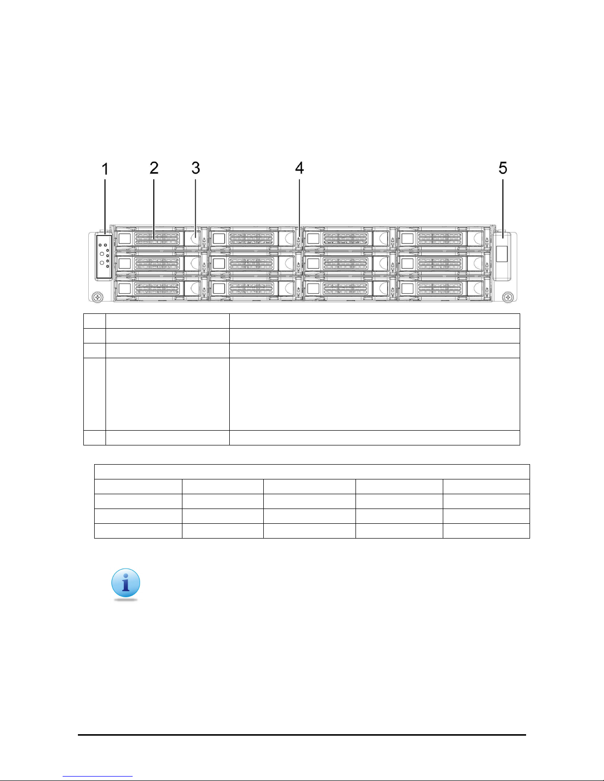
Front View
1.
Front control panel (left) See Front Control Panel on page 4.
2.
HDD bay HDD bay
3.
HDD release lever/ button Use this lever/button to remove the hard drive in HDD bay 1.
4.
HDD status LEDs Top LED :
Normal: Light Green
Fault: Red
Bottom LED:
Active: Dark Green
5.
Logo panel (right) Right panel.
QSSC-980 HDD (x 12) Location
Left Right
Upper HDD12 HDD9 HDD6 HDD3
HDD11 HDD8 HDD5 HDD2
Lower HDD10 HDD7 HDD4 HDD1
Note:
When use 1:1 SKU, there are three HDD ports, A1, B1 and A2, connected to MB.
HDD1~HDD4 are assigned to A1, HDD5~HDD8 are assigned to B1.
HDD9~HDD12 are assigned to A2.
Page 20
錯誤! 尚未定義樣式。
— Introduction
4
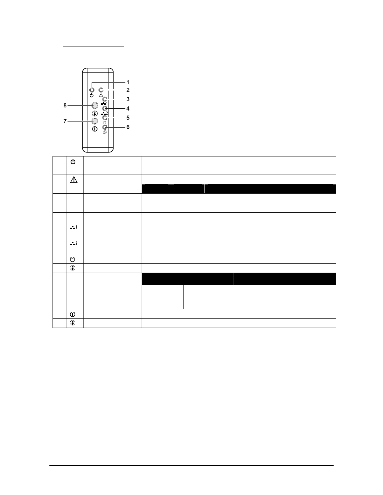
Front Control Panel
1.
Power LED
Power On: solid green
Sleep: blinking green
2.
Status LED Displays status/errors and is controlled by BMC.
Color Condition
Occurrence
Amber Blinking
Non-critical Failure: Fan, voltage, temperature state.
Amber off
OK
3.
NIC1 LED Lights solid green when a connection is made to the NIC1 port, blinks
when NIC1 port is active (access).
4.
NIC2 LED Lights solid green when a connection is made to the NIC2 port, blinks
when NIC2 port is active (access).
5.
HDD Active LED Blinks green for hard drive operation.
6.
System ID LED See table below for behavior.
Color
Condition Occurrence
Blue
Off No identification
Blinking Indicates ID Button pressed on chassis
7.
Power button
Press this button to turn on the QSSC-980 2U.
8.
System ID button Press to light ID LED.
Page 21
錯誤! 尚未定義樣式。
— Introduction
5
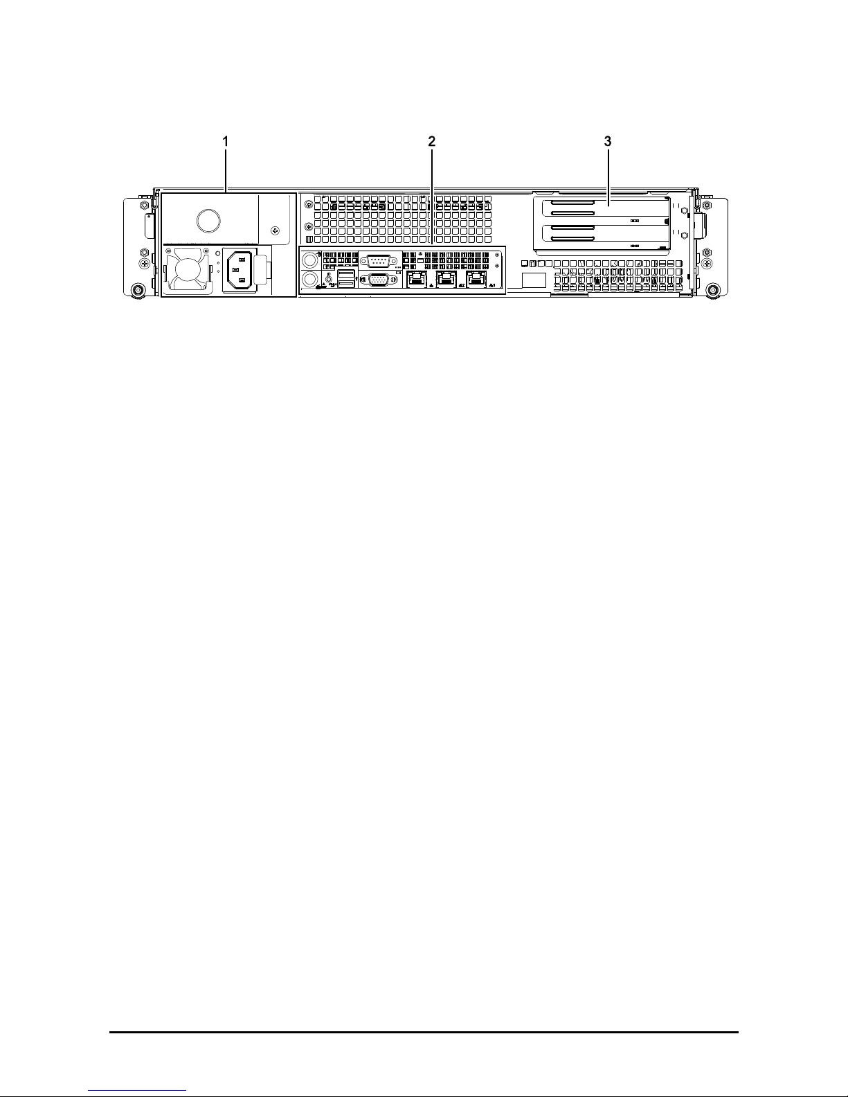
Rear View
1.
Power module Connect the power cable to the socket. An optional power module can be
installed for backup power support.
2.
I/O ports
Connect I/O devices to these ports. See QSSC-980 2U I/O Ports on page 6.
3.
Add-on card
covers
Remove these covers before installing any PCI-e card.
Page 22
錯誤! 尚未定義樣式。
— Introduction
6
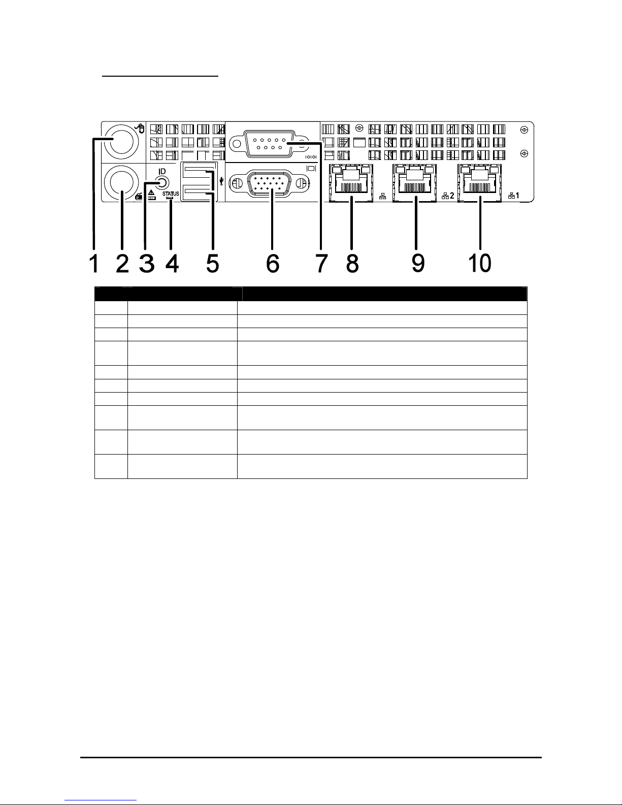
QSSC-980 2U I/O Ports
The QSSC-980 2U has the following I/O port configuration.
Item Port Description
1.
PS2 Mouse Port Connect a PS2 mouse to this port.
2.
PS2 Keyboard Port Connect a PS2 keyboard to this port.
3.
Rear ID Button Press this button for identification.
4.
Status LED Behavior is controlled by BMC
(see on System Controls and LEDs Description page 7).
5.
USB ports Connect USB devices to these two ports.
6.
VGA port Connect a monitor to this port.
7.
Serial port Connect serial devices to this port.
8.
IPMI NIC Connect a RJ-45 jack to this port to link to a BMC LAN from
(AST2050).
9.
NIC2 port Connect a RJ-45 jack to this port to link to a 10/100/1000 Megabit
Ethernet LAN.
10.
NIC1 port Connect a RJ-45 jack to this port to link to a 10/100/1000 Megabit
Ethernet LAN.
Page 23
錯誤! 尚未定義樣式。
— Introduction
7
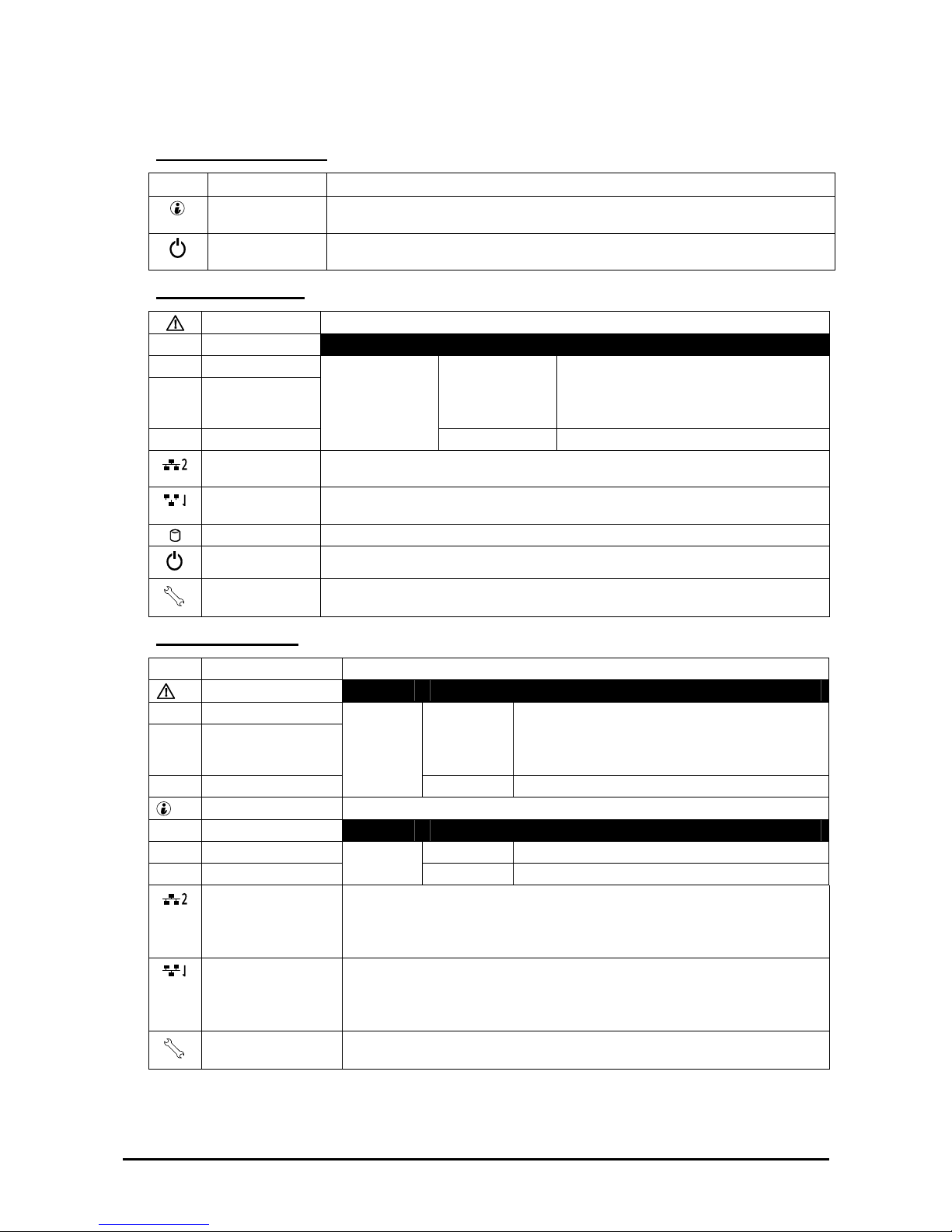
System Controls and LEDs Description
Front System Controls
RESET
Reset Button Push to restart the system when the system is powered on.
Identification
Button
Push to clear the ID LED
Power button
Toggles system power. When system is off, push briefly to power on the PSU and
the system. When power is on, push briefly to turn off.
Front System LEDs
Fault LED Displays status/errors and is controlled by BMC.
Color Condition Occurrence
Blinking Critical Failure: critical Fan, Voltage, Tem-
perature state
Non-Critical Failure: non-critical Fan, Volt-
age, Temperature state, CPU Thermal Trip.
Amber
Off OK
NIC2 LED Lights green when a connection is made to the NIC2 port, blinks off when there is
traffic on the NIC2 port.
NIC1 LED Lights green when a connection is made to the NIC1 port, blinks off when there is
traffic on the NIC1 port.
HDD Active LED Lights for hard drive operation.
Power LED Lights when server is powered on. (This LED is inside the button on the 2.5” option)
Service LED Lights when the BMC port is on, blinks off when there is traffic on the BMC port.
Rear System LEDs
Status System Status LED Displays status/errors and is controlled by BMC.
Color Condition Occurrence
Blinking Critical Failure: critical Fan, Voltage, Temperature
state
Non-Critical Failure: non-critical Fan, Voltage,
Temperature state, CPU Thermal Trip
Amber
Off OK
System ID LED Lights when front or rear ID button is pressed.
Color Condition Occurrence
Off No Identification requested
Blue
On Unit selected for identification
LAN2 LED Link/Act: :Lights green when a connection is made to the NIC2 port, blinks off
when there is traffic on the NIC2 port.
Speed: Lights green when speed is 100 Mbits/sec, Lights Amber when speed is
1000Mbits/sec
LAN1 LED Link/Act: Lights green when a connection is made to the NIC1 port, blinks off
when there is traffic on the NIC1 port.
Speed: Lights green when speed is 100 Mbits/sec, Lights Amber when speed is
1000 Mbits/sec
Service Port Lights when the BMC port is on, blinks off when there is traffic on the BMC port.
Page 24

錯誤! 尚未定義樣式。
— Installing Hardware
8
Chapter 2
IInnssttaalllliinngg HHaarrddwwaarree
Safety Measures
Computer components and electronic circuit boards can be damaged by discharges of static electricity. Working
on computers that are still connected to a power supply can be extremely dangerous. Follow the simple guidelines
below to avoid damage to your computer or injury to yourself.
Always disconnect the computer from the power outlet whenever you are working inside the computer case.
If possible, wear a grounded wrist strap when you are working inside the computer case. Alternatively, discharge
any static electricity by touching the bare metal chassis of the computer case, or the bare metal body of any other
grounded appliance.
Hold electronic circuit boards by the edges only. Do not touch the components on the board unless it is necessary
to do so. Do not flex or stress the circuit board.
Leave all components inside the static-proof packaging until you are ready to use the component for the installation.
Page 25
錯誤! 尚未定義樣式。
— Installing Hardware
9
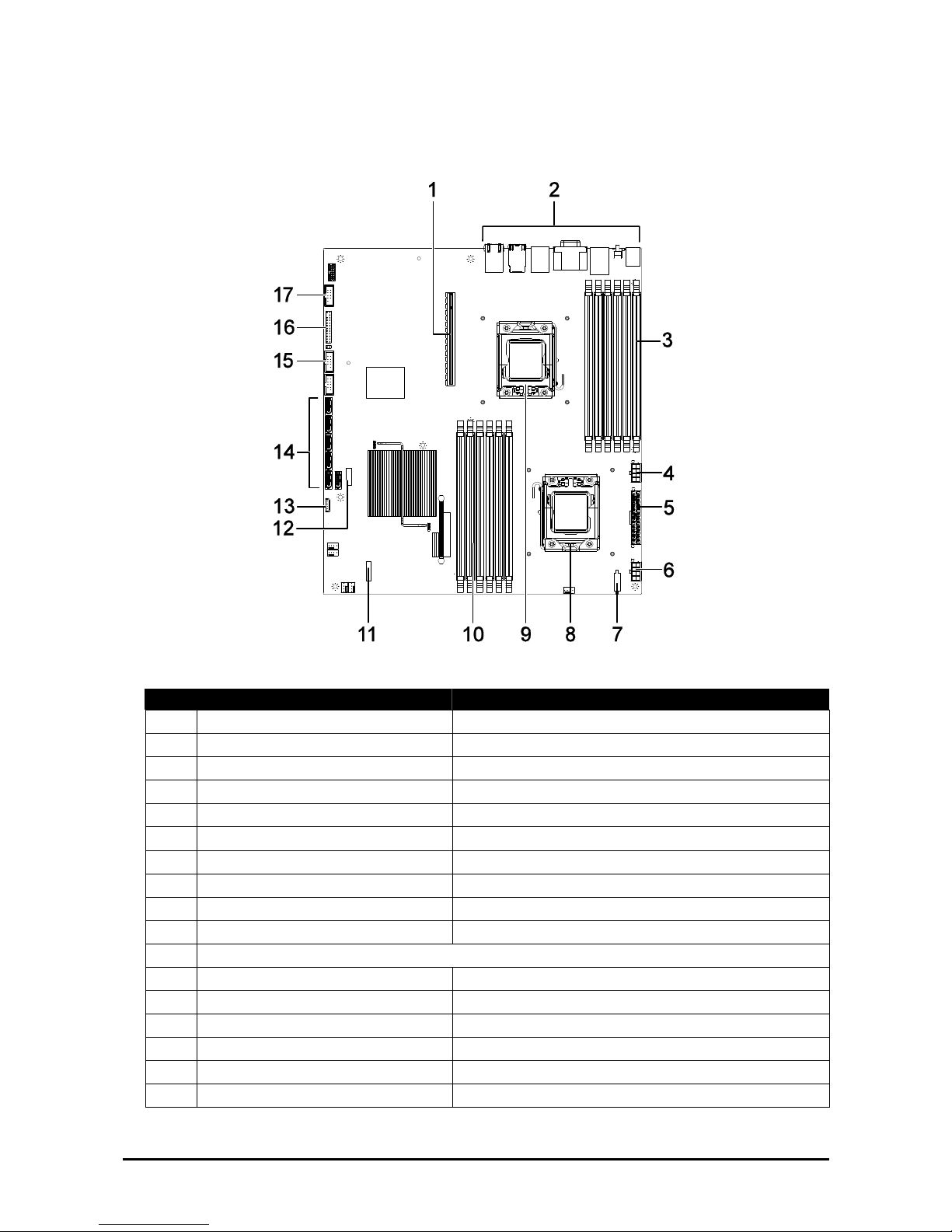
QSSC-980 2U Mainboard Components
The following illustration displays the most important QSSC-980 mainboard components.
Figure 1 – Mainboard diagram
Item Component
1.
PCI slot PCI slot supporting PCI-E
2.
I/O ports See QSSC-980 2U I/O Ports on page 6.
3.
DDR3 DIMM array (CPU 1) 6 x DDR3 DIMM slots – channels 1, 2, and 3.
4.
CPU_PWR1 CPU1 power connector
5.
MAIN_PWR Serverboard main power connector
6.
CPU_PWR2 (CPU2) CPU2 power connector
7.
PSMI Management interface
8.
CPU_2 socket 1366-pin (Socket B) CPU_2 socket for processor
9.
CPU_1 socket 1366-pin (Socket B) CPU_1 socket for processor
10.
DDR3 DIMM array (CPU 2) 6 x DDR3 DIMM slots – channels 4, 5, and 6.
11.
Slot for SAS mezzanine card (optional)
12.
IPMI connector Baseboard management controller
13.
USB port Internal USB port
14.
SATA connectors 6 x SATA II connectors
15.
USB connector Front USB 2.0 connector
16.
Front panel Front panel connector
17.
COM port Front USB 2.0 connector
Page 26
錯誤! 尚未定義樣式。
— Installing Hardware
10
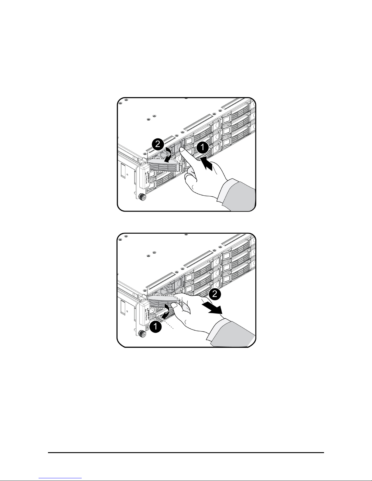
Installing Hard Drives
Follow these instructions to install an HDD:
1. Push the release button in the direction of the arrow .
The HDD tray-locking handle springs open .
2. Open the locking handle and pull to remove the HDD tray .
Page 27
錯誤! 尚未定義樣式。
— Installing Hardware
11
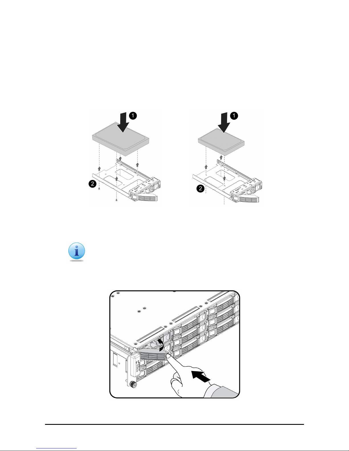
Secure a 3.5” or 2.5” Hard Drive in the 3.5” Tray.
The 3.5” HDD tray can accommodate either a 3.5” HDD or a 2.5” HDD drive. Both options are depicted in the
following guide.
1. Secure the 3.5” hard drive to the tray with four (4) screws as shown. Do not over tighten the screws.
OR
Secure the 2.5” hard drive to the tray with three (3) screws as shown. Do not over tighten the screws.
The following images depict a 3.5” and 2.5” HDD in a 3.5” tray.
3.5” HDD in a 3.5” tray 2.5” HDD in a 3.5” tray
Note:
The 3.5” HDD tray can accommodate either a 3.5” HDD or a 2.5” HDD drive.
2. Replace the HDD tray and push firmly until the sits flush in the HDD bay.
3. Close the locking handle by pushing it in the direction shown until it clicks.
Page 28
錯誤! 尚未定義樣式。
— Installing Hardware
12
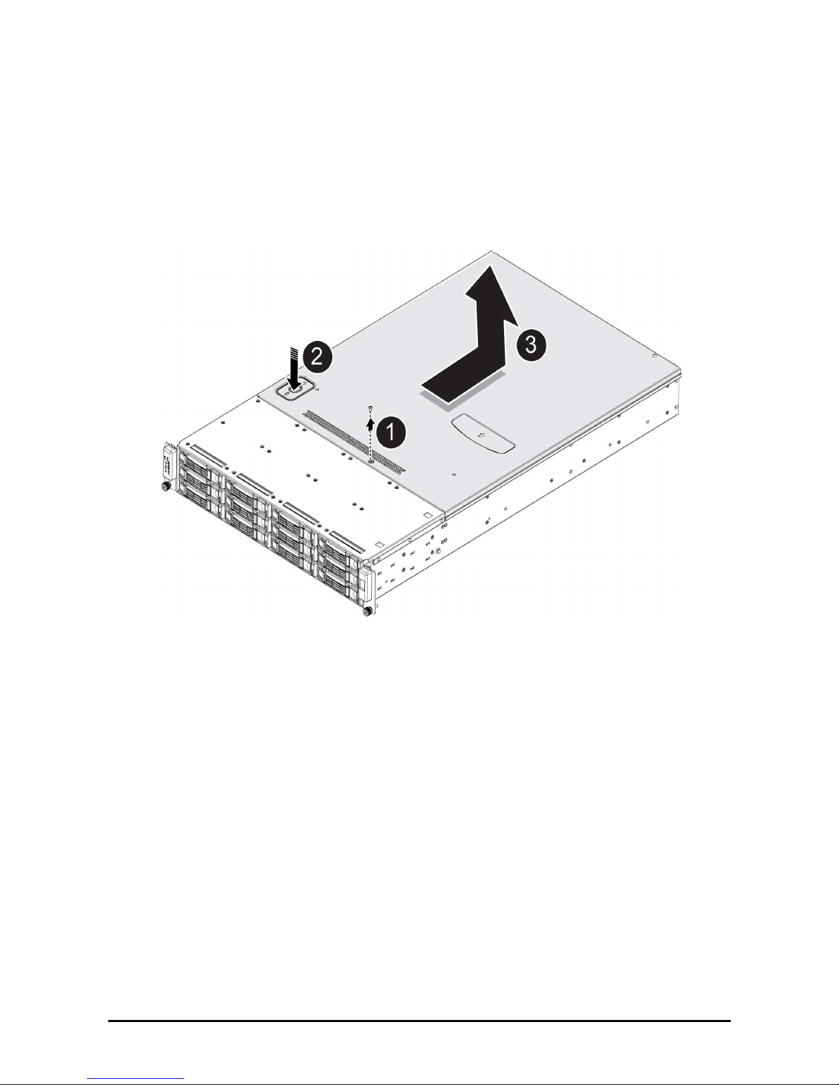
Removing the Chassis Cover
Refer to the following illustrations for instructions on removing the chassis cover:
1. Remove the securing screw .
2. Press the top cover release button .
3. Slide the cover back and then remove .
Page 29
錯誤! 尚未定義樣式。
— Installing Hardware
13
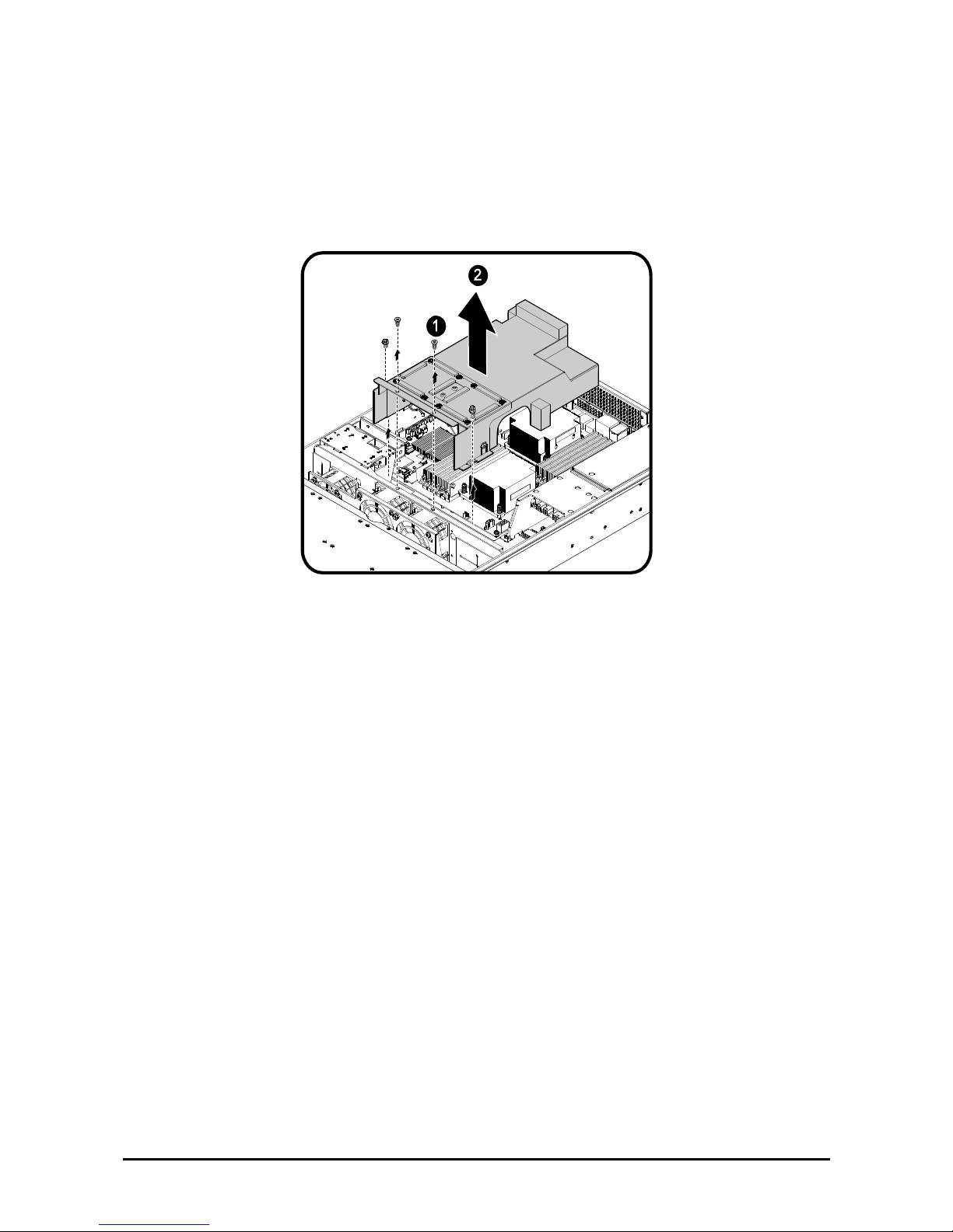
Removing the Fan Duct
Refer to the following instructions to remove the fan duct assembly.
1. Locate the fan duct cover and remove the four (4) securing screws .
2. Carefully lift up the fan duct cover as shown .
Page 30
錯誤! 尚未定義樣式。
— Installing Hardware
14
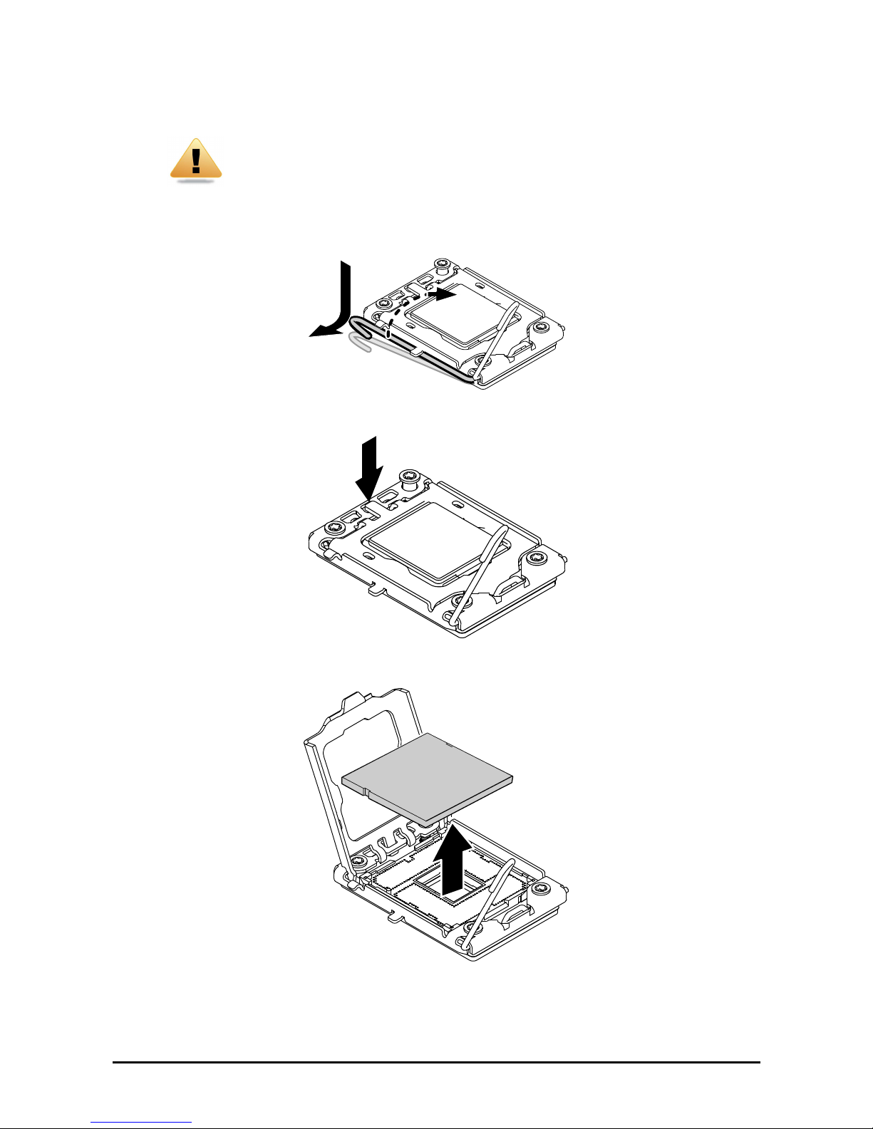
Installing CPUs
WARNING!
In a single CPU configuration, the single processor must be installed in the CPU_1
socket
(see QSSC-980 2U Mainboard Components on page 9 for location).
Refer to the following instructions to install CPUs:
1. Pull the locking lever of the CPU socket out and up as shown.
2. Push down as demonstrated to lift the CPU bracket.
3. Remove the CPU dust cover by lifting the tab marked Remove.
4. Locate the pin-1 corner of the CPU (marked by a small triangle) and the pin-1 corner of the socket; note
that the CPU has notches that fit into the socket.
Page 31

錯誤! 尚未定義樣式。
— Installing Hardware
15
WARNING!
The QSSC-980 2U uses LGA 1366 sockets (Zero Insertion Force sockets), which
are designed for trouble free insertion of the CPUs. After placing the CPU into the
socket, press the lever down and lock in place. If you notice any resistance when
inserting the CPU, ensure that it is aligned correctly.
5. Align the notches and drop the processor into the socket.
6. Replace the CPU bracket and locking lever to lock the processor in place.
7. Repeat steps 1 through 7 for the second CPU.
Notch
Notch
Page 32

錯誤! 尚未定義樣式。
— Installing Hardware
16
Installing Heatsinks
WARNING!
If the server board is to be operated with only a single processor, both heatsinks
must be installed to insure proper cooling.
Refer to the following instructions to install heatsinks:
1. Apply a thermal compound evenly on the top of the CPU.
2. Remove the protective cover from the underside of the heatsink.
3. Place the heatsink on top of the CPU . Tighten the four retaining screws clockwise to secure the heat-
sink .
4. Repeat steps 1 through 4 for the second heatsink.
Page 33

錯誤! 尚未定義樣式。
— Installing Hardware
17
Installing the Fan Duct
Refer to the following instructions to install the fan duct:
1. Carefully replace the fan duct cover as shown .
2. Replace the four (4) securing screws .
WARNING!
Fan ducts are situated over and around the DIMM modules. Ensure that all edges
are not lodged inside the memory banks.
Page 34

錯誤! 尚未定義樣式。
— Installing Hardware
18
Installing the Redundant Power Supply
Follow these instructions to install the redundant power supply:
1. Remove the securing screw and the dummy cover from the redundant power supply bay as shown.
2. Insert the redundant power supply as shown.
Page 35

錯誤! 尚未定義樣式。
— Installing Hardware
19
Installing an Expansion Card
CAUTION!
VOLTAGES CAN BE PRESENT WITHIN THE SERVER WHENEVER AN AC
POWER SOURCE IS CONNECTED. THIS VOLTAGE IS PRESENT EVEN WHEN
THE MAIN POWER SWITCH IS IN THE OFF POSITION. ENSURE THAT THE
SYSTEM IS POWERED-DOWN AND ALL POWER SOURCES HAVE BEEN DISCONNECTED FROM THE SERVER PRIOR TO INSTALLING A PCI CARD.
USE ONLY A QSSC-2U SPECIFIC PCI RISER CARDS WHEN INSTALLING A
PCI CARD.FAILURE TO OBSERVE THESE WARNINGS COULD RESULT IN
PERSONAL INJURY OR DAMAGE TO EQUIPMENT.
You can install expansion cards on the system's riser board. The riser board plugs into the riser connector on the
system board. A second PCI card can be installed. Because the lower and upper PCI cards are installed in the
same manner, both use the following procedure.
Note:
The PCI riser assembly does not include a riser card or any cabling as standard.
To install a PCI card, a riser card must be installed. Refer to riser card user manual
for installation procedures.
1. Remove the riser card. See Replacing the Riser Card on page 26.
2. Remove the PCI dummy cover from the riser assembly.
3. Orient the PCI card with the riser guide slot and push in the direction of the arrow until the PCI card sits
in the PCI card connector . Secure the PCI card with the screw as shown .
4. Repeat Step 3 for a second PCI card.
5. Turn the riser assembly over and replace back on the chassis.
See Replacing the Riser Card on page 26.
Page 36

錯誤! 尚未定義樣式。
— Installing Hardware
20
Installing Memory
The mainboard has twelve DDR3-DIMM slots for the installation of up to twelve memory DIMMS @ DDR31066/1333 memory chips. Refer to QSSC-980 2U Mainboard Components on page 9 for the location of the memory modules.
Refer to the following instructions to install memory modules:
1. Pull the locking latches of the DIMM slot outwards.
2. Align the memory module correctly. Note the notch and obstruction in the following illustration.
3. Press the edge connector of the memory module into the slot. Press down firmly so that the locking
latches of the DIMM slot are levered upwards to secure the memory module in place.
Page 37

錯誤! 尚未定義樣式。
— Installing Hardware
21
Supported DIMM Configuration
The following DIMM configurations are supported by the QSSC-980 server. DIMM slots are numbered 1 to 2 and
designated by 3 channels, A/B/C for CPU1 and D/E/F for CPU2. Populate DIMM slots starting with slot 1: channel 1(A1 for CPU1 and D1 for CPU2). See the following for possible memory configurations.
DIMM Population Rule
Single Processor Population
For single processor population, the following guidelines apply:
• DIMM 1: Single channel.
• DIMM 3: Three channels, populate Single DIMM per channel.
• DIMM 6: Three channels, populate Two DIMMs per channel.
The DIMM population rules are shown below. Populated DIMM slots are denoted with an “O”.
Table 1. Unbuffered DIMM Installation Option for 1P Configuration
Unbuffered DIMM Installation Option for 1P Configuration
DIMM DIMM DIMM DIMM DIMM DIMM
Max Speed
DIMM Processor
A2 A1 B2 B1 C2 C1 Single &
Dual Rank
Quad Rank
1 Processor 1
- O - - - - 1333 1066
3 Processor 1
- O - O - O 1333 1066
6 Processor 1 O O O O O O 1066 800
Page 38

錯誤! 尚未定義樣式。
— Installing Hardware
22
Table 2. Registered DIMM Installation Option for 1P Configuration
Registered DIMM Installation Option for 1P Configuration
DIMM DIMM DIMM DIMM DIMM DIMM
Max Speed
DIMM Processor
A2 A1 B2 B1 C2 C1 Single &
Dual Rank
Quad Rank
1 Processor 1
- O - - - - 1333 1066
3 Processor 1
- O - O - O 1333 1066
6 Processor 1 O O O O O O 1066 800
Dual Processor Population
For dual processor population, the following guidelines apply:
DIMM 2: Single channel per CPU.
DIMM 4: Three channels, populate Single DIMM per channel per CPU.
DIMM 6: Three channels, populate Two DIMMs per channel per CPU.
The DIMM population rules are shown below. Populated DIMM slots are denoted with an “O”.
Table 3. Unbuffered DIMM Installation Option for 2P Configuration
Unbuffered DIMM Installation Option for 2P Configuration
DIMM DIMM DIMM DIMM DIMM DIMM Max Speed
DIMM Processor
A2 A1 B2 B1 C2 C1 Single &
Dual Rank
Quad Rank
Processor 1 - O - - - - 1333 1066
2
Processor 2 - O - - - - 1333 1066
Processor 1 - O - O - O 1333 1066
6
Processor 2 - O - O - O 1333 1066
Processor 1 O O O O O O 1066 800
12
Processor 2 O O O O O O 1066 800
Table 4. Registered DIMM Installation Option for 1P Configuration
Registered DIMM Installation Option for 2P Configuration
DIMM DIMM DIMM DIMM DIMM DIMM Max Speed
DIMM Processor
A2 A1 B2 B1 C2 C1 Single &
Dual Rank
Quad Rank
Processor 1 - O - - - - 1333 1066
2
Processor 2 - O - - - - 1333 1066
Processor 1 - O - O - O 1333 1066
6
Processor 2 - O - O - O 1333 1066
Processor 1 O O O O O O 1066 800
12
Processor 2 O O O O O O 1066 800
Note:
Max speed is dependent on selected CPU.
Page 39

錯誤! 尚未定義樣式。
— Installing Hardware
23
CPU Memory to Speed Configuration
The following table provides corresponding information for CPU type to memory speed. CPUs with 6.4 GT/s
support memory up to 1333 MHz, while 5.86 GT/s support up to 1066 MHz and 4.8 GHz only support 800 MHz.
Memory speed is automatically downgraded to match the supported CPU value. As an example, 1333 MHz memory with an E5530 CPU, rated at 5.86 GT/s, is detected at a speed of 1066 MHz because of the CPU rating. See
the following table for further information.
CPU Number Clock Speed QPI Speed Max Memory Speed
X5570 2.93 GHz
X5560 2.80 GHz
X5550 2.66 GHz
6.4 GT/s 1333/1066/800 MHz
E5540 2.53 GHz
E5530 2.40 GHz
E5520/L5520 2.26 GHz
5.86 GT/s 1066 MHz
E5506/L5506 2.13 GHz
E5504 2.00 GHz
E5502 1.86 GHz
4.86 GHz 800 MHz
Page 40

錯誤! 尚未定義樣式。
— Installing Hardware
24
Replacing the Fan Assembly
In case of fan failure, you can quickly replace the fan assembly.
Follow these instructions to replace the fan assembly:
1. Remove the chassis cover. See Removing the Chassis Cover on page 12.
2. Disconnect the three (3) power cables from the backplane.
3. Remove the single securing screw from the chassis as shown.
4. Slide the assembly to clear the securing pins, and pull up as shown .
5. Select the fan module to replace and remove the screws from the assembly carrier.
6. Replace the fan and reverse steps 5 to 1 to connect the fan assembly.
Page 41

錯誤! 尚未定義樣式。
— Installing Hardware
25
Replacing the Power Supply
In case of a power supply failure, you can quickly replace the power supply unit.
Note:
You can also install an optional backup power supply. Contact your dealer for details. See Installing the Redundant Power Supply on page 18.
Refer to the following instructions to replace the power supply:
1. Grasp the PSU handle and push in the Lock Release latch .
2. Pull the PSU out .
3. Push the new PSU in the direction of the arrow until it sits flush with the chassis and locked in place.
Page 42

錯誤! 尚未定義樣式。
— Installing Hardware
26
Replacing the Riser Card
Refer to the following illustrations for instructions on replacing the riser card:
1. Remove the top cover. See Removing the Chassis Cover on page 12.
2. Firmly grasp the riser assembly and lift up and away. See the following image.
3. Turn the assembly over and place on a clean static mat.
4. Remove the securing screws, and pull out the riser card as shown in the following figure.
To replace the riser card, reverse steps 6 to 1.
Page 43

錯誤! 尚未定義樣式。
— Installing Hardware
27
Replacing the Backplane
WARNING!
Always disconnect power cables before installing or removing any components
from the computer, including the backplane.
Disconnect the power cable before installing or removing any cables from the
backplane.
Make sure that the backplane is securely installed to prevent damage to the system.
To remove the backplane board, perform the following steps:
1. Remove the chassis cover. See Removing the Chassis Cover on page 12.
2. Remove the Fan Duct. See Removing the Fan Duct on page 13.
3. Remove the Fan Assembly. See Replacing the Fan Assembly on page 24.
4. Locate and disconnect the fan and the power cables from the backplane board.
5. Remove the two securing screws from the backplane board.
6. Grasp the backplane and gently remove the board from the chassis.
7. Place the new board in the chassis. Ensure that the board is right side up and the twelve hard-disk driver
connectors face outward.
8. Secure the board with the two screws.
9. Connect the fan and power cables.
10. Replace the Fan Assembly. See Replacing the Fan Assembly on page 24..
11. Replace the Fan Duct. See Removing the Fan Duct on page 13.
12. Replace the Chassis Cover. See Replacing the Chassis Cover on page 29.
Page 44

錯誤! 尚未定義樣式。
— Installing Hardware
28
Replacing the Mainboard
In order to remove the mainboard, you need to disconnect all connections between the mainboard and components
in the case and any cables that are simply in the way.
Note:
When removing any component, wear a properly grounded static strap to prevent
static discharge.
Follow these instructions to replace the mainboard:
1. Unplug the power supply.
2. Remove the chassis cover. See Removing the Chassis Cover on page 12.
3. Remove the PCI riser card assembly. See Replacing the Riser Card on page 26.
4. Remove all installed memory. See Installing Memory on page 20.
5. Remove the heatsinks from the chassis. See Installing Heatsink on page 16.
6. Remove the CPU(s) from the chassis. See Installing CPUs on page 14.
7. Disconnect the power, IPMB, SATA, front panel, and mainboard cable connectors from the mainboard.
See QSSC-980 2U Mainboard Components on page 9.
8. Remove the ten (10) screws securing the mainboard in place.
9. Lift the mainboard out of the chassis in the direction of the arrow, front edge first, to clear the I/O ports.
10. When replacing the mainboard, align holes A and B to position the mainboard correctly in the chassis.
11. Replace the ten (10) screws to secure the mainboard in place.
12. Reconnect the power, IPMB, SATA, front panel, and mainboard connectors to the mainboard. See QSSC-
980 2U Mainboard Components on page 9.
13. Reinstall all removed components.
14. Reinstall the chassis cover. See Replacing the Chassis Cover on page 29.
Page 45

錯誤! 尚未定義樣式。
— Installing Hardware
29
Replacing the Chassis Cover
Refer to the following instructions to replace the chassis cover:
1. Replace cover and slide in the direction shown (1).
2. Replace the securing screw (2).
Page 46

錯誤! 尚未定義樣式。
— BIOS
30
Chapter 3
BBIIOOSS
Setup Menu
The computer employs the latest AMI Core BIOS, which is stored in Flash memory. The Flash memory supports
the Plug and Play specification, and contains a BIOS Setup program, the Power On Self Test (POST) routine, and
the PCI auto-configuration utility.
This mainboard supports system BIOS shadowing enabling the BIOS to execute from 64-bit onboard writeprotected DRAM.
Configure such items as:
Hard drives, diskette drives, and peripherals
Password protection from unauthorized use
Power Management features
This Setup utility should be executed under the following conditions:
When changing the system configuration
When a configuration error is detected by the system and you are prompted to make changes to the Setup
utility
When redefining the communication ports to prevent any conflicts
When changing the password or making other changes to the security setup
Note:
Only items in brackets [ ] can be modified. Items that are not in brackets are display only.
BIOS Setup Options at Boot
The user will be able to initiate SETUP by pressing the respective keys during the POST:
<F2> – Enter the BIOS Setup
Console Redirection
The console redirection allows a remote user to diagnose and fix problems on a server, which has not successfully
booted the OS. The centerpiece of the console redirection is the BIOS Console. The BIOS Console is a Flash
ROM-resident utility that redirects input and output over a serial or modem connection.
The BIOS supports console redirection to a serial port. If serial port based headless server support is provided by
the system, the system must provide support for redirection of all BIOS driven console I/O to the serial port. The
driver for the serial console must be capable of supporting the functionality documented in the ANSI Terminal
Definition.
Enable/Disable Console Redirection
The console redirection function can be enabled/disabled in the BIOS Setup menu.
COM1 for console redirection
COM2 for Serial over LAN
Page 47

錯誤! 尚未定義樣式。
— BIOS
31
Value Description
00H Console Redirection function disable
01H Console Redirection to COM1 (3F8H)
Configuring Special Keys
Console redirection uses ANSI terminal emulation, which is limited to basic ASCII characters. There are no function keys, arrow keys, or control keys in this character set. However, the QSSC-2U BIOS software requires the
use of function keys and control keys for ordinary functions. You can emulate a function key or control key by using a special key sequence called an escape sequence, to represent a specific key.
For console redirection, an escape sequence starts with an escape character. This character can be entered in a variety of different ways depending on the requirements of your terminal emulation software. For example, 0x1b, ^[,
and <Esc> refer to the same escape character.
The following table lists the escape sequence that must be sent to represent a special key or command.
Key ANSI Escape Sequence Windows Platform Design Note
F1 <ESC><Shift>op <ESC>1
F2 <ESC><Shift>oq <ESC>2
F3 <ESC><Shift>or <ESC>3
F4 <ESC><Shift>os <ESC>4
F5 <ESC><Shift>ot <ESC>5
F6 <ESC><Shift>ou <ESC>6
F7 <ESC><Shift>ov <ESC>7
F8 <ESC><Shift>ow <ESC>8
F9 <ESC><Shift>ox <ESC>9
F10 <ESC><Shift>oy <ESC>0
F11 <ESC><Shift>oz <ESC>!
F12 <ESC><Shift>oa <ESC>@
Home <ESC>[<Shift>h <ESC>h
End <ESC>[<Shift>k <ESC>k
Ins <ESC>[2 <ESC>+
Del <ESC>[3 <ESC>-
Page Up <ESC>[5 <ESC>?
Page Down
<ESC>[6 <ESC>/
Reset <ESC><Shift>b <ESC>R<ESC>r<ESC>R
Page 48

錯誤! 尚未定義樣式。
— BIOS
32
The Legend Bar
The legend bar is at the side of the Setup screen. The keys in the legend bar allow you to navigate through the various setup menus. The following table lists the keys found in the legend bar with their corresponding alternates
and functions.
Legend Key Alternate Function
F1 Alt + H Displays the General Help window. It can be enabled from anywhere
in the BIOS.
Esc Alt + X Jumps to the Exit menu or returns to the Main menu from a submenu.
←
— Selects the menu item to the left.
→
— Selects the menu item to the right.
↑ or ↓
Arrow keys Moves the cursor up and down between fields.
Tab Enter Moves the cursor to the next position available in the field.
Shift + Tab — Moves the cursor to previous position available in the field.
Minus key (−)
F5 Scrolls backward through the values for the highlighted field.
Plus key (+) F6, space Scrolls forward through the values for the highlighted field.
Home PgUp Moves the cursor to the field at the top of the window.
End PgDn Moves the cursor to the field at the bottom of the window.
F9 — Sets the parameters for the current menu to their default values.
F10 — Saves the configuration parameters and exits the Setup Utility.
Enter — Will select a sub menu or show a range of options for a field.
General Help
In addition to the Item Specific Help window, the Setup Utility also provides a General Help screen. This screen
can be called up from any menu by pressing [F1] or the [Alt] + [H] combination. The General Help screen lists
the legend keys with their corresponding alternates and functions. To exit the help window, press the Enter or the
Esc key.
Page 49

錯誤! 尚未定義樣式。
— BIOS
33
Main Menu
The main menu displays information about your mainboard and BIOS.
BIOS SETUP UTILITY
Main Advanced Boot Server Security Exit
System Overview
AMIBIOS
Version : QSSC-980_3A01
Build Date:06/19/08
Product Name : QSSC-980
Board Serial Number : 01234567890124
Processor
Genuine Intel(R) CPU @ 0000 2.67GHz
Speed :2666MHz
Counter :1
System Memory
Size :1016MB
System Date [Thu 06/19/2008]
System Time [13:40:55]]
Use [ENTER, [TAB]
or [SHIFT-TAB] to
select a field.
Use [+] or [-] to
Configure System Time.
←→ Select Screen
↑↓ Select Item
+/- Change Field
Tab Select Field
F1 General Help
F10 Save and Exit
ESC Exit
V02.61 ©Copyright 1985-2005, American Megatrends Inc.
*1: Read from FRU
AMIBIOS
Version: displays the BIOS version. Check this version number when updating BIOS from the manufacturer.
Build Date: displays the date the BIOS was created.
Product Name: designated name of the unit.
Board Serial Number: displays the serial number of the board.
Processor
Type: displays the type of CPU installed on the mainboard.
Speed: displays the maximum speed of the CPU.
Counter: displays the number of installed processors.
System Memory
Size: displays how much memory (DRAM) is installed on the mainboard.
System Time: scroll to this item to adjust the time.
System Date: scroll to this item to adjust the date.
Page 50

錯誤! 尚未定義樣式。
— BIOS
34
Advanced Menu
This option displays a table of items that define advanced information about your system.
Warning! Making incorrect settings to items on these pages may cause the system to malfunction. Unless you
have experience adjusting these items, we recommend that you leave these settings at the default
values. If making settings to items on these pages causes your system to malfunction or prevents
the system from booting, open BIOS and choose “Load Optimal Defaults” in the Exit menu to boot
up normally.
BIOS SETUP UTILITY
Main Advanced Boot Server Security Exit
Advanced Settings
Warning: Setting wrong values in below section
may cause system to malfunction.
► CPU Configuration
► Memory Configuration
► SATA Configuration
► SuperIO Configuration
► USB Configuration
► PCI Configuration
► General WHEA Configuration
Configure the CPU
←→ Select Screen
↑↓ Select Item
+/- Change Option
Tab Select Field
F1 General Help
F10 Save and Exit
ESC Exit
V02.61 ©Copyright 1985-2006, American Megatrends Inc.
Page 51

錯誤! 尚未定義樣式。
— BIOS
35
CPU Configuration
Scroll to this item and press Enter to view the following screen:
BIOS SETUP UTILITY
Advanced
Configure advanced CPU settings
Intel (R) Xeon(R) CPU 0000 @ 2.67GHz
CPUID :106A2
Frequency :2.66GHz
FSB Speed :533MHz
Cache L1 :128KB
Cache L2 :1024KB
Cache L3 :8192KB
Ration Status :Unlocked (Min:12, Max:20)
Ratio Actual Value:20
Hardware Prefetcher: [Enabled]*2
Adjacent Cache Line Prefetch: [Enabled]*2
Max CPUID Value Limit: [Disabled]*1
Intel ® Virtualization Tech [Enabled]*2
Execute-Disable Bit Capability [Enabled]*2
Intel(R) HT Technology [Enabled]*2
Active Processor Cores [All]*3
Intel(R) SpeedStep(tm) tech [Enabled]*2
Intel(R) TurboMode tech [Enabled]*2
C3 STATE [Disabled]*2
C6 STATE [Enabled]*2
C7 STATE [Enabled]*2
Disabled for Windows XP
←→ Select Screen
↑↓ Select Item
+/- Change Option
Tab Select Field
F1 General Help
F10 Save and Exit
ESC Exit
V02.61 © Copyright 1985-2005, American Megatrends Inc.
*1: Disabled/Enabled: (Only for CPUs that support this feature.)
*2: Disabled/Enabled: (Only for CPUs that support this feature.)
*3: All/1/2
Note:
Default values shown.
CPUID: Information only. Displays the CPUID.
Frequency: Information only. Displays the current frequency of the processor.
Cache L1: Information only. Displays the size of CPU L1.
Cache L2: Information only. Displays the size of CPU L2.
Cache L3: Information only. Displays the size of CPU L3.
Ratio Status: Display Min/Max ratio.
Page 52

錯誤! 尚未定義樣式。
— BIOS
36
Ratio Actual Value: Information only. Display the ratio at which processors currently run.
Hardware Prefetcher:[Enabled] [Disabled] This should be enabled in order to enable or disable the Hardware
Prefetcher Disable Feature. It is triggered by regular access patterns and helps predict future access, thereby overlapping memory latency with computation. By enabling concurrency between memory accesses and computation,
the computational benefit of higher processor frequencies is maximized.
Adjacent Cache Line Prefetch: [Enabled] [Disabled] This should be enabled in order to enable or disable the
Adjacent Cache Line Prefetch Disable Feature.The cache lines are fetched in pairs. This can be helpful if the data
to be used would continue to the next cache line, causing less cache misses to maximize throughput. When the data is not in adjacent lines, then performance can be slowed, since there will be more cache misses and more time
spent filling the cache lines
Max CPUID Value Limit: [Enabled] [Disabled] Disabled for Windows XP Intel processors from the Pentium
Pro onwards have a maximum CPUID input value of only 02h or 03h. The only exception is the Intel Pentium 4
with Hyper-Threading Technology (HTT). This is where the Max CPUID Value Limit BIOS feature comes in. It
allows you to circumvent problems with older operating systems that do not support the Intel Pentium 4 processor
with Hyper-Threading Technology. When enabled, the processor will limit the maximum CPUID input value to
03h when queried, even if the processor supports a higher CPUID input value.
Virtualization Tech: [Enabled] [Disabled] When enabled, a VMM can utilize the additional HW Caps. provided
by Intel® Virtualization Tech. Note: A full reset is required to change the setting. Designed to support multiple
software environments sharing same hardware resources, each software environment may consist of OS and applications.
Execute- Disable Bit Capability: [Enabled] [Disabled] When disabled, force the XD feature flag to always return
0. The Execute Disable Bit feature (XD bit) can prevent data pages from being used by malicious software to execute code. A processor with the XD bit feature can provide memory protection in either of the following modes:
Legacy protected mode if Physical Address Extension (PAE) enabled. Intel® 64 mode when 64-bit extension
technology is enabled.
Intel(R) HT Technology: [Enabled] [Disabled] When Disabled only one thread per enabled core is enabled. Intel
HT Technology is a processor design that combines hardware multithreading with superscalar processor technology to allow multiple threads to issue instructions each cycle. SMT permits all thread contexts to simultaneously
compete for and share processor resources.
Active Processor Cores: [All] [1] [2] Number of cores to enable in each processor package.
Intel(R) SpeedStep(tm) tech: [Enabled] [Disabled] Intel® Xeon® processors support the Geyserville3 (GV3)
feature of the Enhanced Intel SpeedStep® technology. This feature changes the processor operating ratio and voltage similar to the Thermal Monitor 1 (TM1) feature. It must be used in conjunction with the TM1. The BIOS
implements the GV3 feature in conjunction with the TM1 feature. This technology allows the clock speed of the
processor to be dynamically changed by software.
Intel(R) TurboMode tech: [Enabled] [Disabled] Turbo mode allows processor cores to run faster than marked
frequency in specific condition. Only for Nehalem processor The Turbo Mode feature allows extreme edition processors to program thresholds for power/current which can increase platform performance by 10%.
Intel(R) CSTATE tech: [Enabled] [Disabled} CState: CPU idle is set to C2/C3/C4.
C3 State: [Enabled] [Disabled] Nehalem C state action select.
C6 State: [Enabled] [Disabled] Nehalem C state action select.
C7 State: [Enabled] [Disabled] Nehalem C state action select.
Page 53

錯誤! 尚未定義樣式。
— BIOS
37
Memory Configuration
Scroll to this item and press Enter to view the following screen:
BIOS SETUP UTILITY
Advanced
System Memory Settings
Current Memory Frequency 1333Mhz
Memory Frequency [Auto]*1
Memory Mode [Independent]*2
Throttling – Closed Loop [Enabled]*3
Throttling – Open Loop [Enabled]*3
Enabled/Disabled
←→ Select Screen
↑↓ Select Item
+/- Change Option
F1 General Help
F10 Save and Exit
ESC Exit
V02.61 © Copyright 1985-2006, American Megatrends Inc.
*1
: Auto/Force DDR-800/Force DDR-1066/Force DDR-1333
*2
: Independent/Channel Mirroring/Lockstep/Sparing
*3
: Disabled/Enabled
Current Memory Frequency: 800/1033 /1333 Mhz. Displays the current memory frequency.
Memory Frequency: [Auto] [Force DDR-800] [Force DDR-1033][Force DDR-1333] Forces a DDR3 fre-
quency slower than the common tCK detected via SPD.
Memory Mode: [Independent] [Channel Mirroring][Lockstep][Sparing]. Independent: independent channel. Mir-
roring: mirrors channel space between channel. Lockstep: lockstep between channel 0 and 1. Spare: sparing mode.
Throttling – Closed Loop: [Disabled][Enabled]. BIOS to program Closed Loop throttling for memory comp-
nents.
Throttling–Open Loop: [Disabled][Enabled]. BIOS to program Open Loop throttling for memory components.
Page 54

錯誤! 尚未定義樣式。
— BIOS
38
SATA Configuration
Scroll to this item and press Enter to view the following screen:
BIOS SETUP UTILITY
Advanced
IDE Configuration
ATA/IDE Configuration [Compatiable]*1
Configure SATA#1 as [IDE]*2
► SATA Port0 [Not Detected]
► SATA Port1 [Not Detected]
► SATA Port2 [Not Detected]
► SATA Port3 [Not Detected]
► SATA Port4 [Not Detected]
► SATA Port5 [Not Detected]
Options
Disabled
Compatible
Enhanced
←→ Select Screen
↑↓ Select Item
+/- Change Option
F1 General Help
F10 Save and Exit
ESC Exit
V02.61 © Copyright 1985-2006, American Megatrends Inc.
*1
: Disabled/Compatible/Enhanced
*2
: IDE/RAID/AHIC
SATA#1 Configuration: [Disabled] [Compatible] [Enhanced].
Configure SATA#1: [IDE] [RAID] [AHCI]. [IDE] – Supports up to 4 SATA ports with Parallel ATA emulation.
[AHCI] –Supports all SATA ports using the Advanced Host Controller Interface. [RAID] – Supports configuration of SATA ports for RAID via RAID configuration software. Disappears when the SATA#1 Configuration is
disabled.
SATA Port0-5: [Not Detected] [Hard Disk] [ATAPI CDROM]. Information only. Unavailable when RAID Mode
is enabled.
Page 55

錯誤! 尚未定義樣式。
— BIOS
39
Third IDE Master
Configure SATA#1 as IDE and the following screen appears:
BIOS SETUP UTILITY
Advanced
Third IDE Master
Device :Hard Disk
Vendor :ST320410A
Size :20.0GB
LBA Mode :Supported
Block Mode:16Sectors
PIO Mode :4
Async DMA :MultiWord DMA-2
Ultra DMA :Ultra DMA-2
S.M.A.R.T :Supported
Type [Auto]*1
Select the type of device connected to the
system.
←→ Select Screen
↑↓ Select Item
+/- Change Option
F1 General Help
F10 Save and Exit
ESC Exit
V02.61 © Copyright 1985-2005, American Megatrends Inc.
*1
:Not Installed/Auto/CD/DVD/ARMD
Third IDE Master
Device: displays the type of device assigned to this channel.
Vendor: displays the manufacturer’s name of the device.
Size: displays the size of the device (GB).
LBA Mode: indicates whether LBA access mode is supported or not supported.
Block Mode: indicates whether multi sector transfer is supported.
PIO Mode: indicates whether PIO mode is supported.
Async DMA: indicates whether Async DMA is supported.
Ultra DMA: indicates whether Ultra DMA is supported.
S.M.A.R.T.: indicates whether S.M.A.R.T. mode is supported.
LBA/LARGE Mode: enables LBA access mode.
• Disabled: LBA access mode is disabled
• Auto: LBA is set to optimal or default mode if the device supports it and is not formatted with LBA
mode disabled.
Block Mode: enables multi-sector transfer block mode.
• Disabled: data transfer from and to the device occurs one sector at a time
• Auto: data transfer from and to the device occurs multiple sectors at a time if supported by the device
Page 56

錯誤! 尚未定義樣式。
— BIOS
40
PIO Mode: select the device PIO (Programmed Input/Output) mode, which determines the data transfer mode
used by IDE drives. PIO mode uses the CPU's registers for data transfer.
• Auto: automatically detects optimal or default PIO mode
• 0 ~ 4: select PIO mode 0 to 4
DMA Mode: select the devices DMA (Direct Memory Access) mode which transfers data from channel to
channel without using the CPU, resulting in faster data transfer then when the CPU is used for every byte of
transfer.
• Auto: automatically detects optimal or default DMA mode
• SWDMA0 ~ SWDMA2: select SingleWord DMA 0 to 2
• MWDMA0 ~ MWDMA2: select MultiWord DMA 0 to 2
• UDMA 0 ~ UDMA5: select Ultra DMA 0 to 5
S.M.A.R.T.: (Self Monitoring Analysis and Reporting Technology) reports drive degradation to the operating
system to warn you of potential failure.
• Auto: automatically sets optimal or default S.M.A.R.T. mode
• Disabled: disables S.M.A.R.T.
• Enabled: enables S.M.A.R.T.
32Bit Data Transfer: enables 32-bit data transfer for improved performance.
Page 57

錯誤! 尚未定義樣式。
— BIOS
41
Super IO Configuration
Scroll to this item and press Enter to view the following screen:
BIOS SETUP UTILITY
Advanced
Configure Win627DHG Super IO Chipset
Serial Port1 Address [3F8/IRQ4]*1
Serial Port2 Address [2F8/IRQ3]*1
Allows BIOS to Enable
or Disable Floppy
Controller.
←→ Select Screen
↑↓ Select Item
+/- Change Option
F1 General Help
F10 Save and Exit
ESC Exit
V02.61 ©Copyright 1985-2006, American Megatrends Inc.
*1: Disabled/[3F8/IRQ4]/[3E8/IRQ4]/[2E8/IRQ3]
Super I/O Configuration: enables you to configure the onboard serial ports.
Serial Port1 Address: This option is used to assign the I/O address and IRQ for the first onboard serial port.
The default setting is [3F8/IRQ4].
Serial Port2 Address: This option is used to assign the I/O address and IRQ for the second onboard serial
port. The default setting is [2F8/IRQ3].
Page 58

錯誤! 尚未定義樣式。
— BIOS
42
USB Configuration
Scroll to this item and press Enter to view the following screen:
BIOS SETUP UTILITY
Advanced
USB Configuration
USB Devices Enabled :
1 Keyboard, 1 Mouse
Legacy USB Support [Enabled]*1
USB Functions [12 USB Ports]*2
USB 2.0 Controller [Enabled]*
1
► USB Mass Storage Device Configuration
Enables support for
Legacy USB. AUTO
Option disables
Legacy support if
no USB devices are
connected.
←→ Select Screen
↑↓ Select Item
+/- Change Option
F1 General Help
F10 Save and Exit
ESC Exit
V02.61 ©Copyright 1985-2006, American Megatrends Inc.
*1
: Disabled/Enabled/Auto
*2
: Disabled/2 USB Ports/4 USB Ports/6 USB Ports/8 USB Ports/12 USB Ports
This menu enables you to configure USB devices.
USB Devices Enabled: displays USB devices currently detected.
Legacy USB Support: enables support for legacy USB devices. Select Auto to disable legacy support if no USB
devices are connected.
USB Functions: enables and disables USB host controllers.
USB 2.0 Controller Mode: configures the USB 2.0 controller in HiSpeed (480Mbps) or FullSpeed (12Mbps).
Page 59

錯誤! 尚未定義樣式。
— BIOS
43
PCI Configuration
Scroll to this item and press Enter to view the following screen:
BIOS SETUP UTILITY
Advanced
PCI Configuration
NIC1––––KAWELA [Enabled with PXE]*2
NIC2––––KAWELA [Enabled with PXE]*2
NIC1 MAC Address [xx-xx-xx-xx-xx-xx]
NIC2 MAC Address [xx-xx-xx-xx-xx-xx]
Current QPI Frequency 6.400GT
QPI Links Speed [Full-Speed]
QPI Frequency [Auto]*3
QPI L0s and L1 [Disabled]*1
Crystal Beach / DMA [Disabled]
Intel VT-d [Disabled]
SR-IOV Supported [Disabled]
Active State Power-Management [Disabled]
ME Support [Enabled]*1
Options
Disabled
Enabled
←→ Select Screen
↑↓ Select Item
+/- Change Option
F1 General Help
F10 Save and Exit
ESC Exit
V02.61 ©Copyright 1985-2006, American Megatrends Inc.
*1: Disabled/Enabled
*2: Disabled/Enabled with PXE/Enable without PXE
*3: Auto/4.800GT/5.866GT/6.400GT)
NIC1 – ZOAR: [Disabled][Enabled with PXE][Enabled without PXE]. From IOH PCIE Port.
NIC2 – ZOAR: [Disabled][Enabled with PXE] Enabeld without PXE]. From IOH PCIE Port.
NIC1 MAC Address: Information only. Displays the NIC1 MAC address.
NIC2 MAC Address: Information only. Displays the NIC2 MAC address.
SAS Mezz SWRAID5: [Disabled][Enabled]. This option only be displayed by SAS Mezzanine supported SKU.
Current QPI Frequency: 4.800 GT5.600 GT6.400 GT.
QPI Link Speed: [Slow-Mode][Full-Speed].
QPI Frequency: [Auto][4.800 GT][5.600 GT][6.400 GT].
QPI L0s and L1: [Disabled][Enabled].
Crystal Beach / DMA: [Disabled][Enabled].
Crystal Beach / DCA: [Disabled][Enabled]. It is present if [Crystal Beach / DMA] is [Enabled].
Intel VT-d: [Disabled][Enabled].
SR-IOV Supported: [Disabled][Enabled].
Active State Power- Management: [Disabled][Enabled].
ME Support: [Disabled][Enabled].
Page 60

錯誤! 尚未定義樣式。
— BIOS
44
General WHEA Configuration
Scroll to this item and press Enter to view the following screen:
BIOS SETUP UTILITY
Advanced
General WHEA Configuration
WHEA Support [Enabled]* 1
Enable or disable
Windows Hardware
Error Architecture.
←→ Select Screen
↑↓ Select Item
+/- Change Option
F1 General Help
F10 Save and Exit
ESC Exit
V02.61 ©Copyright 1985-2009, American Megatrends Inc.
*1: Disabled/Enabled
This menu allows you to enable the Windows Hardware Error Architecture.
WHEA Support: Enables or disables the Windows Hardware Error Architecture (WHEA)
Page 61

錯誤! 尚未定義樣式。
— BIOS
45
Boot Menu
This page enables you to set POST boot parameters.
Scroll to this item and press Enter to view the following screen:
BIOS SETUP UTILITY
Main Advanced Boot Server Security Exit
Boot Settings
► Boot Settings Configuration
► Boot Device Priority
► Hard Disk Drives
► Network Device
Configure Settings
during System Boots.
←→ Select Screen
↑↓ Select Item
Enter Go to Sub Screen
F1 General Help
F10 Save and Exit
ESC Exit
V02.61 ©Copyright 1985-2006, American Megatrends Inc.
Boot Settings Configuration
Select this item and press Enter to view the following submenu items:
BIOS SETUP UTILITY
Boot
Boot Settings Configuration
Quiet Boot [Disabled] *1
Bootup Num-Lock [On] *2
Wait For ‘F1’ If Error [Enabled] *
3
POST Timeout [5 seconds] *
Disabled: Displays
normal POST messages.
Enabled: Displays OEM
Logo instead of POST
Messages.
←→ Select Screen
↑↓ Select Item
+/- Change Option
F1 General Help
F10 Save and Exit
ESC Exit
V02.61 © Copyright 1985-2006, American Megatrends Inc.
*1: Disabled/Enabled
*2: Off/On
*3: Disabled/Enabled
Quiet Boot: enable this item to display the OEM logo instead of POST messages. When disabled, normal
POST messages appear.
Page 62

錯誤! 尚未定義樣式。
— BIOS
46
Bootup Num-Lock: sets the state of the keyboard keypad on boot. When set to On, the keypad functions as a
keypad. When set to Off, the keypad functions as auxiliary cursor movement keys.
Wait For ‘F1’ If Error: enable this item to have the system prompt you to press F1 if an error occurs. This
enables you to view the error.
Boot Device Priority
Select this item and press Enter to view the following submenu items:
BIOS SETUP UTILITY
Boot
Boot Device Priority
1st Boot Device [HDD:3M-ST320410A]
2nd Boot Device [Network:IBA GB Slo]
3rd Boot Device [Network:IBA GB Slo]
Specifies the boot
sequence from the
available devices.
A device enclosed in
parenthesis has been
disabled in the
corresponding type
menu.
←→ Select Screen
↑↓ Select Item
+/- Change Option
F1 General Help
F10 Save and Exit
ESC Exit
V02.61 ©Copyright 1985-2006 American Megatrends Inc.
Network Drives
Select this item and press Enter to view the following submenu items:
BIOS SETUP UTILITY
Boot
Network Drives
1st Drive [Network:IBA GE Slo]
2nd Drive [Network:IBA GB Slo]
3rd Drive [Network:IBA GB Slo]
Specifies the boot
sequence from the
available devices.
←→ Select Screen
↑↓ Select Item
+/- Change Option
F1 General Help
F10 Save and Exit
ESC Exit
V02.61 ©Copyright 1985-2009 American Megatrends Inc.
Xxx Drive: [Device Name] [Disabled] Specifies the boot sequence form the available device
Page 63

錯誤! 尚未定義樣式。
— BIOS
47
Server Menu
This page enables you to configure Server parameters.
Scroll to this item and press Enter to view the following screen:
BIOS SETUP UTILITY
Main Advanced Boot Server Security Exit
IPMI Information
Status Of BMC Working
IPMI Specification Version 2.0
BMC Firmware Version 00 00.03
► Set BMC LAN Configuration
► Remote Access Configuration
Restore on AC Power Loss [Power Off] *1
Event Control Interface
View Event Log
Clear BMC System Event Log
Event logging [Enabled]*1
ECC Event Logging [Enabled]*1
PCI Event Logging [Enabled]*2
QPI Event Logging [Enabled]*2
IOH Internal Event Logging [Enabled]*2
NMI on Error [Fatal]*
3
Configure Remote
Access.
←→ Select Screen
↑↓ Select Item
Enter Go to Sub Screen
F1 General Help
F10 Save and Exit
ESC Exit
V02.61 © Copyright 1985-2006 American Megatrends Inc.
*1: Power Off/Power On/Last State
*2: Disabled/Enabled
*3: Disabled/Correctable/Uncorrectable/Fatal
Page 64

錯誤! 尚未定義樣式。
— BIOS
48
BMC LAN Configuration
Scroll to this item and press Enter to view the following screen:
BIOS SETUP UTILITY
Server
LAN Configuration
Channel Number [01]*1
Channel Number Status: Channel number is OK
DHCP Enabled [Disabled]*2
IP Address [xxx.xxx.xxx.xxx]
Subnet Mask [xxx.xxx.xxx.xxx]
GateWay Address [xxx.xxx.xxx.xxx]
Current MAC address in BMC: xx.xx.xx.xx.xx.xx
Enter for IP Address
Configuration
←→ Select Screen
↑↓ Select Item
-+ Change Option
F1 General Help
F10 Save and Exit
ESC Exit
V02.61 © Copyright 1985-2006, American Megatrends Inc.
*1: Default command value is 01, user should not change it.
*2: Disabled/Enabled
Page 65

錯誤! 尚未定義樣式。
— BIOS
49
Remote Access Configuration
Scroll to this item and press Enter to view the following screen:
BIOS SETUP UTILITY
Server
Configure Remote Access Type and parameters
Remote Access [Enabled]*1
Serial port number [COM1]
Base Address, IRQ [3F8h,4]
Serial Port Mode [115200 8,n,1]*2
Flow Control [None]*3
Redirection After BIOS POST [Always]*4
Terminal Type [ANSI]*5
Select Remote Access
type.
←→ Select Screen
↑↓ Select Item
+/- Change Option
F1 General Help
F10 Save and Exit
ESC Exit
V02.61 © Copyright 1985-2006, American Megatrends Inc.
*1: Disabled/Enabled
*2: 115200 8,n,1/57600 8,n,1/38400 8,n,1/19200 8,n,1/09600 8,n,1
*3: None/Hardware/Software
*4: Disabled/Boot Loader/ Always
*5: ANSI/VT100/VT-UTF8
Page 66

錯誤! 尚未定義樣式。
— BIOS
50
Security Menu
This page enables you to set the security parameters.
Scroll to this item and press Enter to view the following screen:
BIOS SETUP UTILITY
Main Advanced Boot Server Security Exit
Security Settings
Supervisor Password : Not Installed
User Password : Not Installed
Change Supervisor Password
Change User Password
Install or Change the
password.
←→ Select Screen
↑↓ Select Item
Enter Go to Submenu
F1 General Help
F10 Save and Exit
ESC Exit
V02.61 © Copyright 1985-2006, American Megatrends Inc.
Supervisor Password: displays whether the supervisor password is installed or not.
User Password: displays whether the user password is installed or not.
Change Supervisor/User Password: you can install a Supervisor password, and if you install a supervisor pass-
word, you can then install a user password. A user password does not provide access to many of the features in the
Setup utility.
If you highlight these items and press Enter, a dialog box appears which lets you enter a password. You can enter
no more than six letters or numbers. Press Enter after you have typed in the password. A second dialog box asks
you to retype the password for confirmation. Press Enter after you have retyped it correctly. The password is required at boot time, or when the user enters the Setup utility.
Page 67

錯誤! 尚未定義樣式。
— BIOS
51
Exit Menu
Scroll to this item and press Enter to view the following screen:
BIOS SETUP UTILITY
Main Advanced Boot Server Security Exit
Exit Options
Save Changes and Exit
Discard Changes and Exit
Discard Changes
Load Optimal Defaults
Exit system setup
After saving the
changes.
F10 key can be used
for this operation.
←→ Select Screen
↑↓ Select Item
+/- Change Option
F1 General Help
F10 Save and Exit
ESC Exit
V02.61 © Copyright 1985-2006, American Megatrends Inc.
Save Changes and Exit: Highlight this item and press Enter to save any changes that you have made in the Setup utility and exit the Setup utility. When the Save Changes and Exit dialog box appears, press Y to save the
changes and exit, or press N to return to the setup main menu.
Discard Changes and Exit: Highlight this item and press Enter to discard any changes that you have made in the
Setup utility and exit the Setup utility. When the Discard Changes and Exit dialog box appears, press Y to discard
changes and exit, or press N to return to the setup main menu.
Discard Changes: select this item and press Enter to discard any changes you have made without leaving the setup utility.
Load Optimal Defaults: if you highlight this item and press Enter, a dialog box asks if you want to install optimal settings for all the items in the Setup utility. Press the Y key to indicate Yes, and then press Enter to install
the optimal settings.
The optimal settings default values are quite demanding and your system might not function properly if you are
using slower memory chips or other kinds of low-performance components.
This concludes the third chapter. The next chapter covers the BMC software agent.
Page 68

錯誤! 尚未定義樣式。
— Using the ESMS
52
Chapter 4
UUssiinngg tthhee EESSMMSS
About ESMS
The Embedded Server Management System (ESMS) is a multi-function management application that provides administrators an efficient utility for remotely managing single or multiple clients.
ESMS provides two console modes–Web Console and Advance Console. The web console mode provides
simple management function to do basic management while the Advance console mode, Java Remote Supervisor Management (Java RSM), supports more advanced management functions. The first half of this
chapter will guide you how to use Web console and the second half of this chapter guide you how to use
Advance console. In combination assists users a comprehensive understanding of using the ESMS.
The following web browsers are supported:
• Internet Explorer 6 and 7
• Mozilla 1.7.13 or later
• Firefox 1.5 or later
ESMS Flow Diagram
The following diagram describes the process flow for the two console modes supported by ESMS.
Figure 2 – ESMS Flow Diagram
Page 69

錯誤! 尚未定義樣式。
— Using the ESMS
53
Enter IP address for Authentication
System default IP address sources from Dynamic Host Configuration Protocol (DHCP) first. If DHCP
server is not detected, the BMC IP will be assigned to https://192.168.1.2/ (or URL) instead of DHCP.
When connecting to the ESMS using a web browser, SSL is automatically activated after the required mode is selected and the user login fields are displayed. This authentication with SSL protection prevents unauthorized
intruders such as hackers from gaining access to the ESMS web server. If authentication is passed, the user can
manage the server by privilege. At the same time, the PHP (PHP Hypertext Preprocessor) records all user information, including user ID and privilege.
Setting the KVM TCP Ports on the Network
Before using the ESMS, ensure that the firewall settings are configured to allow access to the following ports:
• Remote KVM—8890 (TCP), 8900 (TCP)
• Discovery—5000 (Multicast), 2000 (UDP)
• Virtual Storage—9000 (TCP)
Note:
The ESMS requires access to the system’s TCP ports. For information on configuring firewall settings to allow TCP port access, refer to your firewall software user’s
guide.
Choose Console Mode
Two modes of operation are available to access the ESMS application—Web Console and Advance Console.
Figure 3 – Console Mode Screen
Using ESMS Web Console Mode
This mode provides access to Web Console ESMS functions only and is used for minor systems tasks and monitoring purposes for a single server.
ESMS Web Console supports the following functions:
• Web Console
The following figure displays the user authentication web page in Web Console mode.
Page 70

錯誤! 尚未定義樣式。
— Using the ESMS
54
Figure 4 – Web Console Authentication
The default username is root. The default password is changeme.
After passing authentication, the following web page appears.
Figure 5 – Versions Screen
Web Console provides the basic management utility for the user to view system information and events, perform
simple system tasks and modify system configuration of managed servers remotely.
System Information
The System Information tab enables you to view the Version Information, enable Session Time-Out and interval,
and view Components options. Click the System Information tab to view the following web page.
Figure 6 – System Information Screen
Page 71

錯誤! 尚未定義樣式。
— Using the ESMS
55
Versions
Click the Versions tab to view Version Information including: the Device ID, Device Version, Firmware Version,
and IPMI Version numbers.
Figure 7 – Version Information
Session Time-Out
1. Click the Session Time-Out tab.
Figure 8 – Session Time Out Settings
2. Click Enable and select a timeout value from the drop-down list.
3. Click Disable to prevent the embedded web server from logging off.
4. Click Submit to save the changes.
Components
Click the Components tab to view Server Board, CPU and Memory Information.
Server Board Information
Includes Serial Number, BIOS Version, Product ID, Manufacturer, and Manufacture Date.
CPU Information
Includes CPU ID, Status, Socket, Manufacturer, Model and Frequency.
Memory Information
Includes Memory Module, Status, Socket, Module Size, Type and Frequency.
Page 72

錯誤! 尚未定義樣式。
— Using the ESMS
56
Figure 9 – Components Screen
Page 73

錯誤! 尚未定義樣式。
— Using the ESMS
57
System Monitoring
The System Monitoring tab enables the administrator to view data about the system, including LED, system, fan,
temperature and voltage status, and event logs. Click the System Monitoring tab to view the following web page.
Figure 10 – System Monitoring Screen
Sensor Readings
The Sensor Readings tab provides information about system hardware such as the fan speed, internal temperature,
and voltage.
Summary
Click the Summary tab to display a brief overview of system hardware status.
Page 74

錯誤! 尚未定義樣式。
— Using the ESMS
58
Figure 11 – System Monitoring Summary
• Fan Status: indicates the health status of the CPU fans and SYS fans for CPUs and SYS that are installed.
• Temperature Status: indicates the status for such items as the baseboard and processor temperature, and
thermal control.
• Voltage Status: indicates the voltage status for components such as the baseboard, processor Vcc, and
CPUs installed.
Note:
This page will automatically update every 20 seconds.
Page 75

錯誤! 尚未定義樣式。
— Using the ESMS
59
Fan
Click the Fan tab to view CPU and SYS fan information.
Figure 12 – System Monitoring Fan
Note:
This page will automatically update every 10 seconds.
Temperature
Click the Temperature tab to view system component temperature information.
Figure 13 – System Monitoring Temperature
Note:
This page will automatically update every 10 seconds.
Page 76

錯誤! 尚未定義樣式。
— Using the ESMS
60
Voltage
Click the Voltage tab to view system component voltage information.
Figure 14 – System Monitoring Voltage
Note:
This page will automatically update every 10 seconds.
Event Logs
Click the Event Logs tab to view reports about system events.
Figure 15 – System Monitoring Event Logs
• Severity: indicates the nature of the event (non-recoverable, critical, warning, information, return to ok,
unspecified)
• Time Stamp: indicates the time and date the event occurred.
• Description: describes the event in more detail.
• Save Event Logs: save the log to disk. You are prompted to save the event log text file to disk.
• Clear Event Logs: clear the current log.
Page 77

錯誤! 尚未定義樣式。
— Using the ESMS
61
Fault LED
1. Click the Fault LED tab to view the following screen.
Figure 16 – System Monitoring Fault LED
2. Click on the desired setting.
• Turn Fault LED Off: sets the fault LED on the server to off.
Page 78

錯誤! 尚未定義樣式。
— Using the ESMS
62
Configuration
The Configuration tab enables you to set Network, Platform Event Filter, E-mail Notification, Clock and Generate New and Upload SSL Certificate.
Figure 17 – Configuration
Network
1. Click the Network tab to set network parameters.
Figure 18 – Configuration Network
• DHCP: When checked enable DHCP server, an IP address is automatically assigned.
• IP Address: enter a specific IP address to be assigned.
• Net Mask: enter the Net Mask of the LAN.
• Gateway: enter the Gateway of the LAN.
• Mac Address: this field displays the Mac address.
Page 79

錯誤! 尚未定義樣式。
— Using the ESMS
63
• Host Name: enter the Host Name of the LAN, if required.
• DNS Server: enter the DNS Server address of the LAN, if required.
2. Click Submit to save the changes.
Event Filter
The Event Filter tab allows you to modify the Trap Receiver Destination Address.
Click the Event Filter tab to display the following web page.
Figure 19 – Configuration Event Filter
E-mail Notification
The E-mail Notification tab enables you to configure e-mail SMTP server sender and receiver details for E-mail
system events notification.
Click the E-mail Notification tab to display the following web page.
Page 80

錯誤! 尚未定義樣式。
— Using the ESMS
64
Figure 20 – Configuration E-mail Notification
Enter server, sender, and receiver details and click Submit.
Clock
The Clock page displays the server Date and Time.
Click the Clock tab to view the following web page.
Figure 21 – Configuration Clock
SSL Certificate
The SSL Certificate page enables the Administrator to generate a new CSR (Certificate Signing Request) key automatically or upload the key.
Click the SSL Certificate tab to view the following web page.
Page 81

錯誤! 尚未定義樣式。
— Using the ESMS
65
Figure 22 – Configuration SSL Certification
Generating a CSR
Before you can create the SSL Certificate, you must first generate a CSR (Certificate Signing Request) on your
server. A CSR is a body of text that contains encoded information specific to your company and domain name.
You can generate a CSR or upload a manually created CSR.
Figure 23 – Configuration Generating a CSR
Follow these instructions to generate and upload a CSR:
1. Fill in the information in the fields provided.
• Country Name: the two-digit code for a country. Select the country from the drop-down list.
• Organization Name: legal Company or Personal Name, as legally registered in your locality.
• Organization Unit Name: whichever branch of your company is ordering the certificate.
• Locality Name: city or location (for example, “Los Angeles”).
• State or Province Name: state (for example, “California”).
• Common Name: the domain name for which you are requesting the SSL certificate.
• E-mail Address: your email address.
Page 82

錯誤! 尚未定義樣式。
— Using the ESMS
66
2. Click Submit.
3. A CSR key is generated and uploaded automatically.
Uploading a Manually Created CSR
1. Click the Browse button next to Certificate Upload, and browse to the location of the saved key, for ex-
ample Savekey.pem.
Figure 24 – Configuration Uploading a Manually Created CSR
2. Click Upload to upload the key.
3. Once the upload is completed, close the browser.
4. Open a new browser and log in. The certificate file is the CSR previously uploaded.
5. After you have generated or uploaded the CSR, click Submit to save the changes.
User Management
The User Management web page enables the administrator to change the administrative account password, and to
add, modify, and delete users and set user privileges.
User Accounts
Click the User Accounts tab to view the following web page.
Figure 25 – User Management User Accounts
Page 83

錯誤! 尚未定義樣式。
— Using the ESMS
67
Adding an user account
1. Click Add button. The following screen appears.
Figure 26 – User Management Adding User Accounts
2. Type the Username in the text box.
3. Type the Password in the text box and type it again for confirmation.
4. Type the E-mail address in the text box.
5. Type the Phone number in the text box
6. Select the privilege to assign to this user administrator
• Administrator
• Operator
• User
• Call Back
7. Select Status to Enable or Disable the user account
8. Click Submit to save the user.
Editing User Information
After a User is added, the administrator can change the user’s password, e-mail, phone, and privileges, prevent the
user access, or delete the user.
Page 84

錯誤! 尚未定義樣式。
— Using the ESMS
68
Figure 27 – User Management Editing User Information
• Edit
Change E-mail: Click to change the user’s mail.
Change Phone: Click to change the user’s phone.
Change Privilege: Click to change the user’s privileges.
Disable: Click to prevent the user access to the server.
• Delete: Click to remove the user from the system.
• Change Password: Click to change the user’s password.
Changing Password
Follow these steps to change password.
1. Under the username root, click Change Password button. The following screen appears.
Figure 28 – User Management Changing Password
2. Type the new password.
3. Type the password again for confirmation.
4. Click Submit to save the new password.
Page 85

錯誤! 尚未定義樣式。
— Using the ESMS
69
ADS Configuration
The ADS Configuration web page enables the administrator to configure an Active Directory Server (ADS).
Figure 29 – User Management ADS Configuration
ADS Configuration requires a Domain Name Server (DNS), an Active Directory Server (ADS), a Certificate Authority Server (CAS), and an AD certificate.
1. In the ADS Configuration page, enter the file path of the CA certificate or browse to the location.
2. Click Browse to upload the Certificate exported from the AD server.
3. Enter Primary DNS (Domain Name Server IP) and Root Domain (AD server Domain).
4. In the Clock Settings page, ensure BMC shows the same time as the AD Server.
5. Click Submit.
6. Log off, and log in to the Web GUI with the username and password you set in AD server.
Page 86

錯誤! 尚未定義樣式。
— Using the ESMS
70
Remote Control
Click the Remote Control tab to view the following web page.
Remote Power Control
This feature enables the administrator to power on or power down the system remotely.
Note:
The IPMI connector must be connected to enable this function.
Click the Remote Power Control tab to view the following web page.
Figure 30 – User Management Remote Power Control
• In the Power Control frame, select Power Off (On) from the drop down menu, then click Submit to
turn off the remote server.
OR
• Select Reset, then click Submit to reset the remote server.
Page 87

錯誤! 尚未定義樣式。
— Using the ESMS
71
Maintenance
The Maintenance web page enables you to update the firmware, BIOS and reset the firmware.
Firmware Update
Use the Firmware Update feature to upgrade to the latest firmware version. See Using Firmware Management on
page 100 for more information on updating firmware.
Click the Firmware Update tab to view the following web page.
Figure 31 – Maintenance Firmware Update
BIOS Update
Use the BIOS Update feature to upgrade to the latest BIOS version.
Click the BIOS Update tab to view the following web page.
Figure 32 – Maintenance BIOS Update
Reset Firmware
Use the Reset firmware web page to reset the firmware to the factory default configuration.
1. Click the Reset Firmware tab to view the following web page.
Page 88

錯誤! 尚未定義樣式。
— Using the ESMS
72
Figure 33 – Maintenance Reset Firmware
2. Click Reset Firmware to restore the default values.
Using ESMS Advance Console Mode
This mode provides access to all ESMS functions and is designed for administrator systems tasks and monitoring for multiple servers.
ESMS Advance Console supports the following functions:
• Server Summary
• Server Management
• Server Monitor
• Web Console
• Remote KVM (Graphic console redirection with KVM over IP)
• Virtual Storage (Virtual media redirection)
• Firmware Management
• Power Control Management
Choosing Advance Console mode begins the Java web start mechanism that initiates the download of the jnlp
launch file and java library and launches the Java Remote Supervisor Management (RSM) utility.
Note:
Before choosing Advance Console mode, ensure that the Java runtime environment (JRE6 or later) is correctly installed.
Figure 34 – Advanced Console Login
Java RSM
The Java RSM combines maximum functionality with minimal screen usage, providing versatility without the
need for additional windows. All supported functions are integrated into one, easy to manage window that can be
applied to multiple BMC hosts simultaneously.
The main window is split up into three panels—BMC Host List, Function Selection, and Management.
Page 89

錯誤! 尚未定義樣式。
— Using the ESMS
73
Figure 35 – Java RSM Panel Description
Item Description
BMC Host List Panel (Red)
Displays tree structure that will display information for all discovered BMC hosts.
Function Selection Panel
(Yellow)
Lists all supported functions. Users can select functions by using
the TAB buttons.
Management Panel (Blue)
Management panel for all related functions.
Refresh
Refresh button for current server list tree. Click to scan all MBC
hosts located in the LAN and obtain the latest BMC information.
Search
Utility to provide search functionality for the BMC host. Advanced
options are available for searching large server lists.
Automatic Server Discovery
The Java RSM discovery function automatically detects all BMC hosts residing on the local or remote area networks by sending multicast packets to all BMC hosts during startup. When the DISD residing in the BMC host
firmware receives the discovery multicast packet, it responds by sending a UDP packet with BMC information to
the Java RSM.
Note:
The local and remote routers must be configured to allow the transmission of multicast protocols to enable the discovery function to auto-detect BMC hosts.
Receipt of the UDP packet information adds the BMC host to the BMC Host List.
Page 90

錯誤! 尚未定義樣式。
— Using the ESMS
74
Figure 36 – Auto Server Discovery Diagram
Authentication and Privilege
Before using Java RSM, the user must finish the authentication process to Java RSM functions acquire privileges.
Enter a valid user ID and password to access the selected host.
The following web page displays after a successful authentication to the selected BMC Host.
Figure 37 – Authentication and Privilege Window
Authentication failure results in displaying the following web page.
Page 91

錯誤! 尚未定義樣式。
— Using the ESMS
75
Figure 38 – Authentication Failure Result
BMC Host List Functions
The Java RSM supports common Host List functions to quickly configure remote BMC hosts. These functions are
accessed through a pop-up menu by right-clicking the mouse button on the required host.
Figure 39 – BMC Host List
Network Configuration
The Network Configuration screen is used to make changes to the Host Name, IP Address, Netmask, Gateway
and DNS information of BMC hosts detected by the Java RSM.
Right-click the desired host and select Config Network Setting to display the Network Configuration screen.
Page 92

錯誤! 尚未定義樣式。
— Using the ESMS
76
Figure 40 – Network Configuration Settings
Make any desired changes to the information displayed and click Submit to save the new configuration.
Note:
Deselect Assign IP Address By DHCP Server to make changes to IP, Netmask,
and Gateway information.
Page 93

錯誤! 尚未定義樣式。
— Using the ESMS
77
Using Server Summary
System summary briefs information of remote server host. Item descriptions are summarized in the following table.
Figure 41 – Using Server Summary
No. Item Description
1
Host Address Indicates the BMC host IP Address
2
MAC Address Indicates the BMC host Ethernet card MAC address
3
Host Name Indicates the BMC host name
4
Firmware Indicates the current firmware version of BMC host
5
BIOS Indicates the current BIOS version of remote server host
6
Serial Number Indicates the serial number of server board
7
Product Indicates the product id of server board
8
SEL Count Indicates the current count of system event log
9
Power State Indicates current DC power state of remote server host
10
PEF State Indicates if the PEF (Platform Event Filter) function is en-
able/disable
11
Fault LED Indicates if the Fault LED is turning on/off
Page 94

錯誤! 尚未定義樣式。
— Using the ESMS
78
Using Server Management
The Server Management tab provides access to the Account Management, Platform Event Filter and Notification
Configuration sub-functions.
Account Management
The Account Management sub-function is designed to add, modify, and delete user accounts and their associated
application privileges.
Figure 42 – User Account Management
No. Item Description
1 Host Selection
Select the desired host from the drag down list.
2
User Account
Management
Add, Modify, and delete users or change user passwords.
3
Privilege
Management
Select the desired application privileges associated with the selected group.
Managing User Accounts
The User Account Management panel is used to add, update, and delete user accounts and change their associated
passwords using the four management buttons provided.
• New—click New to display the new user screen. Enter the required information including the group to which
the new user belongs and the Status.
1
2
3
Page 95

錯誤! 尚未定義樣式。
— Using the ESMS
79
Figure 43 – Managing User Accounts
Click Submit to add the new user.
• Update—select a user and click Update to display the update screen.
Figure 44 – Managing User Accounts Updates
Make any desired modifications and click Submit to save the changes.
• Delete—select the user(s) and click Delete to remove the selected user(s). A confirmation message displays.
Figure 45 – User Accounts Deleting
Click Yes to delete the user(s).
• Change Password— select a user and click Change Password to display the password change screen.
Figure 46 – User Accounts Changing Password
Make any desired modifications and click Submit to save the changes.
Page 96

錯誤! 尚未定義樣式。
— Using the ESMS
80
Managing Function Privileges
Every function of the Java RSM requires specific privilege to execute and the Privilege Management panel determines what privileges are associated with a particular user group. All users belong to one of four groups—
Administrator, Operator, User, and Callback—on a sliding scale of function privilege, Administrator being the
most powerful group.
Figure 47 – Managing Function Privileges
To change group privileges, check or deselect the desired boxes for each group and click Save to save changes.
Note:
The example shows the default privilege settings for all groups.
The Java RSM automatically checks if the current user is authorized to use a specific function and displays an error message if the user’s privilege is insufficient.
Figure 48 – Managing Function Unauthorized Privilege
Platform Event Filter
User can configure the Platform Event Filter (PEF) configuration of remote BMC host in using PEF.
Page 97

錯誤! 尚未定義樣式。
— Using the ESMS
81
Figure 49 – Platform Event Filter
No. Item Description
1
PEF configuration target host filter area. (Yellow)
Utility for filter the wanted information of target host.
2
Global Configuration of Platform Event Filter
(Red Block)
Show the current global configuration of target host and provide the adjust function that user can configure the
configuration by selecting the radio button, checking the check
box.
3
PEF Policy configuration area
(Blue Block)
Display current policy of target
4
Combo box for listing the selected hosts from the server tree
list on the left side.
As doing filtering action, the combo box provide for choosing
the target host.
5
Button for reload the latest configuration date from remote
BMC host.
6
Button for saving the adjusted configuration to remote BMC
host
7
Button for add now PEF policy record
8
Button for delete the selected policy record.
9
Power State Indicate current DC power state of remote server host
10
PEF State
Indicate if the PEF (Platform Event Filter) function is enable/disable
11
Fault LED Indicate if the Fault LED is turning on/off
Page 98

錯誤! 尚未定義樣式。
— Using the ESMS
82
Note:
When multi-users are using PEF, click the Reload button to obtain the latest data.
Maximum 6 configurations can be recorded.
Notification Configuration
User can configure the mail notification to allow remotely BMC host to send system event alert through mail.
Figure 50 – Notification Configuration Screen
No. Item Description
1
Notification configuration target host filter
area. (Yellow)
Utility to filter the desired information of target host.
2
Notification mail sender information and configuration area. (Blue)
Displays the current notification sender mail information.
The text fields are editable.
3
Notification mail receiver configuration area Displays current notification mail receiver.
4
List the selected hosts from the server tree list from the left
column. For filtering action, the combo box provides choosing
the target host.
5
Reload the latest configuration date from remote BMC host.
6
Save the configuration settings to remote BMC host .
7
Add new mail receiver address records.
8
Button for deleting the selected mail receiver address record.
Page 99

錯誤! 尚未定義樣式。
— Using the ESMS
83
Note:
Accounts set in Account Management will be automatically in the Default Mail List.
Maximum 7 accounts will be listed in Default Mail List.
Using Server Monitor
The Server Monitor displays information about specific remote system status. All discovered hosts relay information to the Server Monitor, which is then sorted in to an Event Log, and item specific sub-functions including
system temperature, system voltage, system fan speed, and system components.
Event Log
The Event Log records system events in the form of a table for all discovered BMC hosts. Filters applied to the
log reduce the content to specific events requested by the user.
Figure 51 – Server Monitor Event Log
No. Item Description
1 Action Panel
Select the host log to display from the drop down menu or delete
the log for the selected host.
2 Filter Panel
Add Filters to the log output to target specific events.
3 Event Log Panel
Displays system events for the specified host in chronological order—most recent to least recent.
Applying Event Log Filters
To Filter the Event Log, perform the following steps:
1. Select the Host and/or Severity filters from the drop down menus.
2. Click Submit.
The log is re-ordered by the specified filters.
1
2
3
Page 100

錯誤! 尚未定義樣式。
— Using the ESMS
84
System Temperature
All system environmental conditions sensed by BMC are recorded on the Temperature page directly from the sensor build integrated in the remote server.
Figure 52 – Server Monitor System Temperature
No. Item Description
1 Filter Panel Select the host temperature conditions to display.
2
Temperature
Information Panel
Displays system temperature statistics for the specified host and
sensor in the following columns:
LNCT—lower non-critical threshold value
LCT—lower critical threshold value
UNCT—upper non-critical threshold value
UCT—upper critical threshold value
Value—the actual temperature value recorded by the sensor
State—the sensor state (if known)
1
2
 Loading...