


USER MANUAL
AMPAQ-PWM Amplifier
Set Up and Configuration
CAPTIVATE. MOTIVATE. GRADUATE.

© 2016 Quanser Inc., All rights reserved.
电子信息产品污染控制管理办法 (中国 RoHS)
中国客户 Naonal Instruments 符合中国电子信息产品中限制使用某些有害物质命令 (RoHS)
。
关于Naonal Instruments 中国 RoHS合规性信息,请登录 ni.com/environment/rohs_china
(For informaon about China RoHS compliance, go to ni.com/environment/rohs_china)
Quanser Inc.
119 Spy Court
Markham, Ontario
L3R 5H6
Canada
info@quanser.com
Phone: 1-905-940-3575
Fax: 1-905-940-3576
Printed in Markham, Ontario.
For more information on the solutions Quanser Inc. offers, please visit the web site at:
http://www.quanser.com
This document and the software described in it are provided subject to a license agreement. Neither the software nor this document may be
used or copied except as specified under the terms of that license agreement. All rights are reserved and no part may be reproduced, stored in
a retrieval system or transmitted in any form or by any means, electronic, mechanical, photocopying, recording, or otherwise, without the prior
written permission of Quanser Inc.
Waste Electrical and Electronic Equipment (WEEE)
This symbol indicates that waste products must be disposed of separately from municipal household waste, according to Directive
2002/96/EC of the European Parliament and the Council on waste electrical and electronic equipment (WEEE). All products at the
end of their life cycle must be sent to a WEEE collection and recycling center. Proper WEEE disposal reduces the environmental
impact and the risk to human health due to potentially hazardous substances used in such equipment. Your cooperation in proper
WEEE disposal will contribute to the effective usage of natural resources. For information about the available collection and
recycling scheme in a particular country, go to ni.com/citizenship/weee.
This product meets the essential requirements of applicable European Directives as follows:
• 2006/95/EC; Low-Voltage Directive (safety)
• 2004/108/EC; Electromagnetic Compatibility Directive (EMC)
FCC NOTICE
This device complies with Part 15 of the FCC Rules. Operation is subject to the following two conditions: (1) this device may not cause harmful
interference, and (2) this device must accept any interference received, including interference that may cause undesired operation.
Industry Canada Notice
This Class A digital apparatus complies with Canadian ICES-003.
Cet appareil numérique de la classe A est conforme à la norme NMB-003 du Canada.
AMPAQ-PWM User Manual 2

CONTENTS
1 Presentation 4
1.1 Description 4
2 Components 5
3 Specifications 7
4 Fuse Installation 8
5 Wiring Procedure 10
5.1 Cable Nomenclature 10
5.2 Typical Connections 11
6 Troubleshooting 12
7 Technical Support 12
AMPAQ-PWM User Manual
DRAFT - August 15, 2016

1 PRESENTATION
1.1 Description
The Quanser AMPAQ-PWM, pictured in Figure 1.1, is a pulse width modulated (PWM) current amplifier designed
to power Quanser experiments. The AMPAQ-PWM is a single channel amplifier, meaning it can power a single
load. The AMPAQ-PWM replaces the UPM line of power amplifiers with additional benefits, including a generic
data acquisition board (DAQ) interface for increased flexibility, current sensing capability, and an auxiliary E-Stop
connector to allow a single E-Stop button to stop multiple devices.
Figure 1.1: Quanser AMPAQ-PWM
Caution: This equipment is designed to be used for educational and research purposes and is not intended
for use by the general public. The user is responsible to ensure that the equipment will be used by
technically qualified personnel only.
Caution: If the equipment is used in a manner not specified by the manufacturer, the protection provided by
the equipment may be impaired.
AMPAQ-PWM User Manual 4

2 COMPONENTS
The components on the front and back panels of the AMPAQ-PWM are depicted in Figure 2.1. Each component
on the AMPAQ has an identification number that corresponds to a short description given in Table 2.1. The pin out
information for the analog sensor’s mini-DIN connectors and the 16-pin digital I/O connector header are shown in
Figure 2.2.
ID Name Description Electrical
Range
1 Amplifier Command connector The input command signal from the DAQ is a voltage
that controls the output current. The AMPAQ-PWM adjusts the output duty cycle to maintain the commanded
output current.
2 Current Sense connector This connector provides a voltage proportional to the
actual output current. Scaling is 1 Volt = 2.1 Amps. The
AMPAQ-PWM must be connected to a load in order for
the Current Sense connector to output a voltage.
3 Status LED Indicates if the amplifier is powered up, as well as the
status of the amplifier. When the amplifier is powered
up but disabled, the LED turns red. When the amplifier
is powered up and enabled, the LED turns green.
4 To Load connector This connector provides power to the load. The output
current is controlled by the Amplifier Command signal.
5 Calibrate LED Indicates the calibration status of the connected device
(i.e. Shake Table II).
6 E-Stop connector The AMPAQ-PWM requires an E-Stop (emergency
stop) button to be connected. If no E-Stop button is
connected, the AMPAQ-PWM is disabled by default.
7 Auxiliary E-Stop connector Connector for an additional E-Stop to enable daisy-
chaining stop commands to multiple devices.
8 From Device connector Carries the sensor I/O from the device including en-
coder signals, limit switch states, etc.
9 Limit Switch LEDs Indicate the status of the limit switches on the connected
device
10 Encoder Output connector Connector to output the device encoder signal to an ex-
ternal DAQ device
11 Digital I/O Output connector Connector to output the digital signals from the device
sensors to an external DAQ device
12 S1-S4 Analog Sensor Output
connectors
13 S1-S4 Analog Sensor Input con-
nectors
14 Fuses Replaceable fuses to protect the amplifier
15 Power switch Amplifier power switch
16 Power connector Used to connect the amplifier to the mains
Used to send the analog sensor signals from the connected device to an external DAQ
Used to properly power the analog sensors on the connected device
±10 V
3.75 A Cont.,
15 A Peak
Low:0-0.8 V,
High:2-5.5 V
±12 V
Table 2.1: AMPAQ-PWM components
Caution: Do not exceed the maximum PWM Load ratings 3.75 A continuous, 15 A peak, and 240 VAC.
Caution: Do not replace the power cable provided with one of lower quality or rating.
AMPAQ-PWM User Manual
DRAFT - August 15, 2016
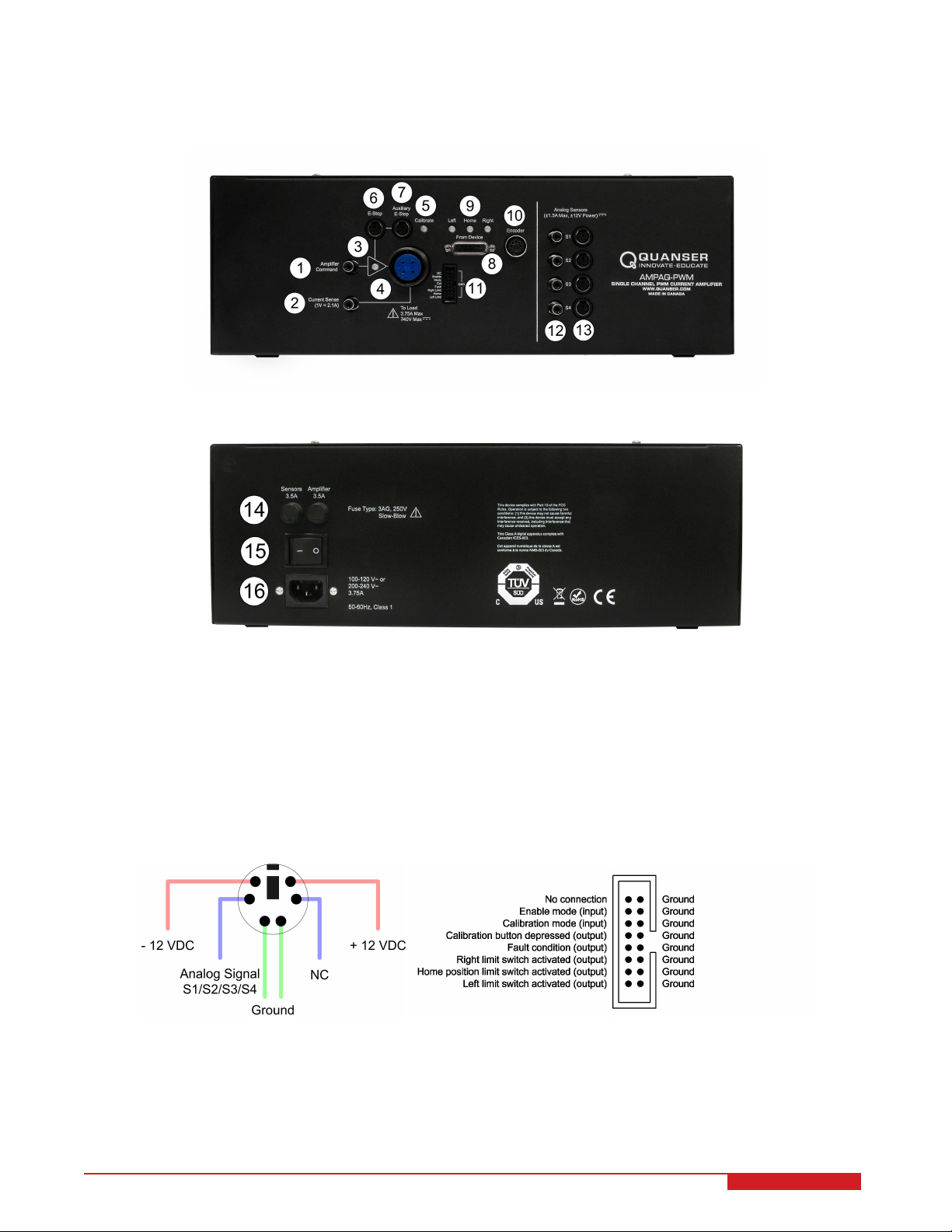
(a) Front
(b) Back
Figure 2.1: AMPAQ-PWM components
(a) Front (b) Back
Figure 2.2: AMPAQ-PWM analog and digital sensor connectors
AMPAQ-PWM User Manual 6

3 SPECIFICATIONS
Table 3.1 lists the AC input requirements for the AMPAQ-PWM. The PWM output specifications are given in Table
3.2, and the general amplifier specifications are listed in Table 3.3.
AC Input Specifications Value
Input Voltage Range 100 VAC - 120 VAC or
200 VAC - 240 VAC
Input Frequency Range 50 Hz - 60 Hz
AC Current Rating 3.75 A
Fuses 3.5 A, 250 V, 3AG Slow Blow
Protection Class Class I
Table 3.1: AC Input Specifications
PWM Output Specifications Value
Maximum Continuous Output Current 3.75 A
Maximum Peak Output Current 15 A
(Maximum duration approximately 2 seconds.)
Maximum Output Voltage 240 VAC
(Output voltage is dependent on the input voltage.)
Switching Frequency 20 kHz
Table 3.2: PWM Output Specifications
Caution: Do not exceed the maximum PWM load ratings of 3.75 A continuous, 15 A peak, and 240 VAC.
AMPAQ-PWM User Manual
DRAFT - August 15, 2016

Amplifier Specifications Value
Amplifier Command Input ± 10 V
Current Sense Output 1 V = 2.1 A
Digital Inputs Low-level: 0 V - 0.8 V
High-level: 2.0 V - 5.5 V
Digital Outputs Low-level: 0 V - 0.6 V
High-level: 4.1 V - 5.2 V
Mass 10.4 kg
Dimensions 0.39 m × 0.39 m × 0.14 m
Environmental
• Standard rating
• Indoor use only
• Altitude up to 2000m
• Maximum relative humidity of 80% up to 31◦C decreasing linearly to 50% relative humidity at 40◦C
• Pollution Degree 2
• Mains supply voltage fluctuations up to ±10% of the
nominal voltage
• Maximum transient overvoltage 2500V
• Marked degree of protection to IEC 60529: Ordinary
Equipment (IPX0)
Table 3.3: Amplifier Specifications
Caution: Precaution must be taken during the connection of this equipment to the AC outlet to make sure
the grounding (earthing) is in place and the ground wire is not disconnected.
Caution: Avoid covering the fan during operation to prevent premature thermal shutdown of the amplifier.
Caution: Do not position the equipment so that it is difficult to operate the on/off switch.
Caution: The AMPAQ-PWM devices are made to be used with Quanser designed experiment kits that have
particular actuators. Use caution if the AMPAQ-PWM is being used with your own actuator. Any
load to be used with the AMPAQ-PWM should have a minimum inductance of 0.1 mH.
Caution: Do not use the cables provided with the AMPAQ-PWM to wire it to experiments that use a different
amplifier module. The AMPAQ-PWM can be used with such experiments only if plant specific
cables are available.
4 FUSE INSTALLATION
The AMPAQ-PWM has two 3.5 Amp fuses that protect the amplifier from overcurrent through the main power connector. If you find your unit does not output power from the To Load connector, or otherwise stops functioning, check
the fuses.
Caution: Make sure the power to the amplifier is disconnected before changing any fuses!
Follow this procedure to install or replace the fuses in the AMPAQ-PWM:
AMPAQ-PWM User Manual 8

1. The fuse holders are located at the rear of the unit, shown in Figure 2.1 with ID #14.
2. Make sure the amplifier power cable is disconnected.
3. Remove both fuse holders. To do this, push and twist the knob counter-clockwise and pull the fuse holder out
as illustrated in Figure 4.1.
Figure 4.1: Remove fuse holders
4. As shown in Figure 4.2, remove the old fuses from the holders and insert the new ones.
Figure 4.2: Replacing the fuse in the fuse holder
5. Ensure the fuse being installed is a 3.5 A, 250 V, 3AG Slow Blow fuse. For example, the following fuses are
acceptable replacements:
• Digi-Key: 283-2750-ND,
• Electrosonic: MDL-3-1/2
Caution: Installing the wrong fuse rating may result in damage to your amplifier.
6. Install the fuse holders back into the amplifier. Push the fuse holder into the panel and twist the knob clockwise
until secure.
7. Connect the power cable to the back of the amplifier.
AMPAQ-PWM User Manual
DRAFT - August 15, 2016

5 WIRING PROCEDURE
5.1 Cable Nomenclature
The cables used to connect the Quanser AMPAQ-PWM to a Quanser DAQ and experiment are shown in Table 5.1.
Depending on your configuration, not all these cables are necessary.
Cable Type Description
2xRCA to 2xRCA RCA-to-RCA cables connect the AMPAQ-PWM Ampli-
fier Command and Current Sense connectors to the
DAQ. RCA-to-RCA cables are also used to connect the
S1, S2, S3, and S4 Analog Sensor outputs to the DAQ.
Three pairs are supplied.
(a) RCA Cable
4-pin-Amphenol
to 4-socketAmphenol
This cable connects the output of the AMPAQ-PWM to
the desired load.
(b) Motor Cable
(c) E-Stop
(d) From Device Cable
(e) Encoder Cable
E-Stop The E-Stop must be connected to the AMPAQ-PWM for
proper operation. The E-Stop button locks in the disabled position when pressed. To release the E-Stop,
twist the red button clockwise.
DB15 to DB15 This cable connects the AMPAQ-PWM From Device
connector to the Shake Table II circuit board. It carries the three limit switch signals, the motor Hall effect
signals, and the motor encoder signals. It also supplies
the DC power required by the sensors.
5-pin-stereo-DIN to
5-pin-stereo-DIN
This cable carries the encoder signals between the
AMPAQ-PWM Encoder connector and the DAQ. These
signals are: +5 VDC power supply, ground, channel A,
and channel B. (Channel Z is optional.)
AMPAQ-PWM User Manual 10

Cable Type Description
6-pin-mini-DIN to
6-pin-mini-DIN
This cable connects an external analog sensor to the
AMPAQ-PWM S1, S2, S3, or S4 Analog Sensor input.
The cable also supplies ± 12 VDC from the AMPAQPWM to power the sensor.
(f) Analog Cable
16-pin Ribbon Cable
(g) Digital I/O Cable
Split 16-pin Ribbon
Cable
(h) Split Digital I/O Cable
This cable connects the Digital I/O connector on the
AMPAQ-PWM to a Q2-USB or QPIDe terminal board.
This cable connects the Digital I/O connector on the
AMPAQ-PWM to a Q8-USB.
Table 5.1: Cables used to connect the AMPAQ-PWM to a Quanser DAQ and experiment
5.2 Typical Connections
Refer to the experiment-specific User Manual and Laboratory Guide for wiring instructions.
AMPAQ-PWM User Manual
DRAFT - August 15, 2016

6 TROUBLESHOOTING
Follow the steps given below based on your issue with the AMPAQ-PWM.
Amplifier does not power up.
• Make sure the power cable is firmly connected to the power connector on the back of the amplifier
• Verify that the fuse is not burnt. If the fuse is burnt, see Section 4 for furst rating and replacement information.
Motor/load is not being driven.
• Verify that the fuse is not burnt. If the fuse is burnt, see Section 4 for furst rating and replacement information.
• If the AMPAQ-PWM is being used with a Quanser system, verify that all the connections illustrated in the User
Manual for that Quanser product have been made correctly.
• If the Emergency stop switch is connected to the amplifier, make sure the red button is in the upper position to
enable the amplifier. The amplifier cannot be enabled when the button is in the lower position. The Enabled
LED on each channel should be lit. Twist to release the red button into the enabled position.
7 TECHNICAL SUPPORT
To obtain support from Quanser, go to http://www.quanser.com/ and click on the Tech Support link. Fill in the form
with all the requested software and hardware information as well as a description of the problem encountered. Also,
make sure your e-mail address and telephone number are included. Submit the form and a technical support person
will contact you.
AMPAQ-PWM User Manual 12

Mix and match components and peripherals to suit your education or research needs
AMPAQ-L2 AMPAQ-L4 AMPAQ-PWM
VoltPAQ-X1 VoltPAQ-X2 VoltPAQ-X4
QPIDe
Q2-USB
Q8-USB Q1-cRIO
NI Terminal
Board
Quanser’s range of control peripherals includes ampliers and data acquisition boards. They can be purchased
separately to control educational or research-grade plants. Mix and match these peripherals with Quanser plants
and control design software to accelerate control system design and implementation.
To nd the right peripherals for your teaching or research needs, please email info@quanser.com.
©2016 Quanser Inc. All rights reserved.
INFO@QUANSER.COM +1-905-940-3575 QUANSER.COM
Solutions for teaching and research. Made in Canada.
 Loading...