


I
PITX-MX60 Series User’s Manual
PITX-MX60 Series
Standard / Extended Temperature
Single Board Computer in Pico-ITX Form Factor
with NXP® ARM® Cortex®-A9 Core i.MX6 Processor
User’s Guide

II
PITX-MX60 Series User’s Manual
Contact Info: Quanmax Inc.
4F, No. 415, Ti-Ding Blvd. Sec. 2NeiHu District,
Taipei 114Taiwan
Tel: +886-2-2799-2789
Fax: +886-2-2799-7399
Visit our site at: www.quanmax.com
© 2017 Quanmax Inc. All rights reserved.
The information in this user’s guide is provided for reference only. Quanmax does not assume any
liability arising out of the application or use of the information or products described herein. This user’s
guide may contain or reference information and products protected by copyrights or patents and does
not convey any license under the patent rights of Quanmax, nor the rights of others.
Quanmax is a registered trademark of Quanmax. All trademarks, registered trademarks, and trade
names used in this user’s guide are the property of their respective owners. All rights reserved. This
user’s guide contains information proprietary to Quanmax. Customers may reprint and use this user’s
guide in other publications. Customers may alter this user’s guide and publish it only after they remove
the Quanmax name, cover, and logo.
Quanmax reserves the right to make changes without notice in product or component design as
warranted by evolution in user needs or progress in engineering or manufacturing technology.
Changes which affect the operation of the unit will be documented in the next revision of this user’s
guide.

Content
3
PITX-MX60 Series User’s Manual
Content
Content.......................................................................................................................3
Figures.......................................................................................................................4
Tables.........................................................................................................................5
Safety Instructions......................................................................................................6
Before You Begin.........................................................................................6
When Working Inside a Computer...............................................................6
Preventing Electrostatic Discharge..............................................................7
Preface....................................................................................................................... 9
How to Use This Guide................................................................................9
Unpacking....................................................................................................9
Regulatory Compliance Statements ............................................................9
Warranty Policy.........................................................................................10
Maintaining Your Computer ....................................................................... 11
Chapter 1 Introduction..............................................................................................14
Overview ................................................................................................... 14
Product Specifications...............................................................................15
System Block Diagram..............................................................................16
Mechanical Dimensions.............................................................................17
Chapter 2 Hardware Settings...................................................................................18
Overview ................................................................................................... 18
Jumper Settings and Pin Definitions.......................................................... 19
Jumper Settings ......................................................................................20
Internal Connector Pin Assignment.........................................................21
Rear Panel Pin Assignments...................................................................27

Figures
4
PITX-MX60 Series User’s Manual
Figures
Figure 1 Block Diagram ............................................................................. 16
Figure 2 Mechanical Dimensions............................................................... 17
Figure 3 Jumper Connector .......................................................................18
Figure 4 Jumper and Connector Locations................................................19
Figure 5 Rear Panel IO.............................................................................. 27

Tables
5
PITX-MX60 Series User’s Manual
Tables
Table 1 PITX-MX60 Series Specification....................................................15
Table 2 Jumper List....................................................................................20
Table 3 JP4 Backlight Enable Selection ....................................................20
Table 4 JP5 Backlight Power Selection ..................................................... 20
Table 5 SW1 Boot Device Selection ..........................................................20
Table 6 Internal Connector Pin List............................................................21
Table 7 BAT1 RTC Power Input Wafer....................................................... 21
Table 8 CN1 Micro-Phone Input Wafer.......................................................21
Table 9 CN2 Head-Phone Output Wafer....................................................21
Table 10 CN3 Left Channel 3W S pe aker Outp ut Wafer .............................22
Table 11 CN4 Right Channel 3W Speaker Output Wafer...........................22
Table 12 CN5 COM2 RS-232/422/485 Wafer............................................ 22
Table 13 CN6 COM1 RS-232 Wafer.......................................................... 22
Table 14 CN7 GPIO/SPI/I2C Wafer............................................................23
Table 15 CN8 Micro USB2.0 OTG Connector............................................ 23
Table 16 CN10 Front Panel Header...........................................................23
Table 17 CN11 Debug Port Header............................................................23
Table 18 CN12 USB2.0 Wafer.................................................................... 23
Table 19 CN13 MCU Update Header.........................................................24
Table 20 CN18 Backlight Power Output Wafer ..........................................24
Table 21 CN19 Micro-SD Card Cage......................................................... 24
Table 22 CN20 CAN Bus Wafer................................................................. 24
Table 23 LVDS1 18/24-bit, 1/2-channel LVDS Connector..........................25
Table 24 MPCIE1 Full Size Mini-PCI Express Socket................................25
Table 25 SIM1 Micro SIM Card Holder.......................................................26
Table 26 Rear Panel Connector List.......................................................... 27
Table 27 CN9 HDMI Connector.................................................................. 27
Table 28 CN14 GbE RJ-45 Connector....................................................... 27
Table 29 CN15 10/100 RJ-45 Connector................................................... 27
Table 30 CN16 Dual USB2.0 Type-A Connector........................................28
Table 31 J1 +12VDC Power Input Jack......................................................28

Safety Instructions
6
PITX-MX60 Series User’s Manual
Safety Instructions
Before You Begin
Before handling the product, read the instructions and safety guidelines on the
following pages to prevent damage to the product and to ensure your own personal
safety . Re fer to the “ Advis ories” section in the Preface for advisory conventions us ed
in this user’s guide, including the distinction between Warnings, Cautions, Important
Notes, and Notes.
Always use caution when handling/operating a computer. Only qualified,
experienced, authorized electronics service personnel should access the
interior of a computer. The power supplies produce high voltages and
energy hazards, which can cause bodily harm.
Use extreme caution when installing or remo ving co mponents. Refer to the
installation instructions in this user’s guide for precautions and procedures.
If you have any questions, please contact Quanmax Post-Sales Technical
Support.
WARNING
High voltages are present i nside the chassi s when the unit’ s pow er cord is
plugged into an electrical outlet. Turn off system power, turn off the power
supply, and then disconnect the power cord from its source before
removing the chassis c over. Turning of f the sy stem pow er sw itch doe s not
remove power to componen ts.
When Working Inside a Computer
Before taking covers off a computer, perform the following steps:
1. Turn off the computer and any peripherals.
2. Disconnect the computer and peripherals from their power sources or
subsystems to prevent electric shock or system board damage. This does not
apply when hot swapping parts.

Safety Instructions
7
PITX-MX60 Series User’s Manual
3. Follow the guidelines provided in “Preventing Electrostatic Discharge” on the
following page.
4. Disconnect any telephone or telecommunicat ions lines fr om the computer.
In addition, take note of these safety guidelines when appropriate:
To help avoid possible damage to system boards, wait five seconds after
turning off the computer before removing a component, removing a system
board, or disconnecting a peripheral device from the computer.
When you disconnect a cable, pull on its connector or o n its strain-relief loop,
not on the cable itself. Some cables have a connector with locking tabs. If you
are disconnecting this type of cable, press in on the locking tabs before
disconnecting the cable. As you pull connectors apart, keep them evenly
aligned to avoid bending any connector pins. Also, before connecting a cable,
make sure both connectors are correctly oriented and aligned.
CAUTION
Do not attempt to service the system yourself except as explained in this
user’s guide. Follow installation and troubleshooting instructions closely.
Preventing Electrostati c Discharge
Static electricity can harm system boards. Perform service at an ESD workstation
and follow proper ESD procedure to reduce the risk of damage to components.
Quanmax strongly encourages you to follow proper ESD procedure, which can
include wrist straps and smocks, when servicing equipment.
You can also take the following steps to prevent damage from electrostatic
discharge (ESD):
When unpacking a static-sensitive component from its shipp i ng carton, do not
remove the component ’s antistatic packing material until y ou ar e r ea dy to install
the component in a computer. Just before unwrapping the antistatic packaging,
be sure you are at an ESD workstation or grounded. This will discharge any
static electricity that may have built up in your body.

Safety Instructions
8
PITX-MX60 Series User’s Manual
When transporting a sensitive component, f i rst place it in an antistatic container
or packaging.
Handle all sensitive components at an ESD workstation. If possible, use
antistatic floor pads and w ork bench p a ds.
Handle components and boards with care. Don’t touch the components or
contacts on a boar d. H old a b oard by it s edges or by it s m et al mounti ng bracket .
Do not handle or store sy stem bo ards near str ong electros t atic, el ectr omagn etic,
magnetic, or radioactive fields.

Preface
9
PITX-MX60 Series User’s Manual
Preface
How to Use This Guide
This guide is designed to be us ed as step-by -step instructi ons for ins tallati on, and a s
a reference for operation, troubleshooting, and upgrades.
NOTE
Driver downloads and additional information are available under
Downloads on our web site: www.quanmax.com.
Unpacking
When unpacking, follow these steps:
1. After opening the box, save it and the packing material for possible future
shipment.
2. Remove all items from the box. If any items listed on the purchase order
are missing, notify Quanmax customer service immediately.
3. Inspect the product for damage. If there is damage, notify Quanmax
customer service immediately. Refer to “Warranty Policy” for the return
procedure.
Regulatory Compliance Statements
This section provides the FCC compliance statement for Class A devices.
FCC Compliance Statement for Class A Devices
The product(s) described in this user’s guide has been tested and found to comply
with the limits for a Class A digital device, pursuant to Part 15 of the FCC Rules.
These limits are designed to provide reasonable protection against harmful
interference when the equipment is operated in a commercial environment. This
equipment generates, uses, and can radiate radio frequency energy and, if not
installed and used in accordance with the user’s guide, may cause harmful
interference to radio communications. Operation of this equipment in a residential

Preface
10
PITX-MX60 Series User’s Manual
area (domestic environment) is likely to cause harmful interference, in which case
the user will be required to correct the interference (take adequate measures) at
their own expense.
Changes or modificati ons not expr essly approv ed by Quanmax could v oid the us er 's
authority to operate the equipment.
NOTE
The assembler of a personal computer system may be required to test
the system and/or make necess ary modific ations i f a sy stem is foun d to
cause harmful interference or to be noncompliant with the appropriate
standards for its intended use.
Warranty Policy
Limited Warranty
Quanmax Inc.’s detailed Limited Warranty policy can be found under Support at
www.quanmax.com. Please consult your distributor for warranty verification.
The limited warranty is void if the product has been subjected to alteration, neglect,
misuse, or abuse; if any repairs have been attempted by anyone other than
Quanmax or its authorized agent; or if the failure is caused by accident, acts of God,
or other causes beyond the control of Quanmax or the manufacturer. Neglect,
misuse, and abuse shall include any installation, operation, or maintenance of the
product other than in accordance with the user’s guide.
No agent, dealer, distributor, serv ice comp any, or other party is authorized to chang e,
modify, or extend the terms of this Limited Warranty in any manner whatsoever.
Quanmax reserves the right to make changes or improvements in any product
without incurring any obligation to similarly alter productspreviously purchased.
Return Procedure
For any Limited Warranty return, please contact Support at www.quanmax.com and
login to obtain a Return Material Authorization (RMA) Number. If you do not have an
account, send an email to support@quanmax.com to apply for one.
All product(s) returned to Quanmax for service or credit must be accompanied by a
Return Material Authorization (RMA) Number. Freight on all returned items must be
prepaid by the customer who is responsible for any loss or damage caused by
common carrier in transit. Returns for Warranty must include a Failure Report for
each unit, by serial number(s), as well as a copy of the original invoice showing the

Preface
11
PITX-MX60 Series User’s Manual
date of purchase.
To reduce risk of damage, returns of product must be in a Quanmax shipping
container. If the original container has been lost or damaged, new shipping
containers may be obtained from Quanmax Customer Service at a nominal cost.
Quanmax owns all parts removed from repaired products. Quanmax uses new and
reconditioned parts made by various manufacturers in performing warranty repairs
and building replacement products. If Quanmax repairs or replaces a product, its
warranty term is not extended.
Shipments not in compliance with this Limited Warranty Return Policy will not be
accepted by Quanmax.
Limitation of Liability
In no event shall Quanmax be liable for any defect in hardware, software, loss, or
inadequacy of data of any kind, or for any direct, indirect, incidental, or
consequential damages in connection with or arising out of the performance or use
of any product furnished hereunder. Quanmax’s liability shall in no event exceed the
purchase price of the product purchas ed her e und er. The foregoing limita ti on o f
liability shall be equally applicable to any service provided by Quanmax or its
authorized agent.
Maintainin g Your Computer
Environmental Factors
Temperature
The ambient temperature within an enclosure may be greater than room
ambient temperature. Installation in an enclosure should be such that the
amount of air flow required for safe operation is not compromised.
Consideration should be given to the maximum rated ambient temperature.
Overheating can cause a variety of problems, including premature aging and
failure of chips or mechanical failure of devices.
If the system has been exposed to abnormally cold temperatures, allow a
two-hour warm-up period to bring it up to normal operating temperature before
turning it on. Failure to do so may cause damage to internal components,
particularly the hard di sk dri v e.
Humidity
High-humidity can cause moisture to enter and accumulate in the system. This
moisture can cause corrosion of internal components and degrade such

Preface
12
PITX-MX60 Series User’s Manual
properties as electrical resistance and thermal conductivity. Extreme moisture
buildup inside the system can result in electrical shorts, which can cause
serious damage to the system.
Buildings in which climate is controlled usually maintain an acceptable level of
humidity for system equipment. However, if a system is located in an unusually
humid location, a dehumidifier can be used to maintain the humidity within an
acceptable range. Refer to the “Specifications” section of this user’s guide for
the operating and storage humidity specifications.
Altitude
Operating a system at a high altitude (low pressure) reduces the efficiency of
the cooling fans to cool the system. This can cause electrical problems related
to arcing and corona effects. This condition can also cause sealed components
with internal pressure, such as electrolytic capacitors, to fail or perform at
reduced efficiency.
Power Protection
The greatest threats to a system’s supply of power are power loss, power spikes,
and power surges caused by electrical storms, which interrupt system operation
and/or damage system components. To protect your system, always properly
ground power cables and one of the following devices.
Surge Protector
Surge protectors are available in a variety of types and usually provide a level
of protection proportional with the cost of the device. Surge protectors prevent
voltage spikes from entering a system through the AC power cord. Surge
protectors, however, do not offer protection against brownouts, which occur
when the voltage drops more than 20 percent below the normal AC line voltage
level.
Line Conditioner
Line conditioners go beyond the over voltage protection of surge protectors.
Line conditioners keep a system’s AC power source voltage at a fairly constant
level and, therefore, can handle brownouts. Because of this added protection,
line conditioners cost more than surge protectors. However, line conditioners
cannot protect against a complete loss of power.

Preface
13
PITX-MX60 Series User’s Manual
Uninterruptible Power Supply
Uninterruptible power supply (UPS) systems offer the most complete protection
against variations on power because they use battery power to keep the server
running when AC power is lost. The battery is charged by the AC power while it
is available, so when AC power is lost, the battery can provide power to the
system for a limited amount of time, depending on the UPS system.
UPS systems range in price from a few hundred dollars to several thousand
dollars, with the more expensive unit s allowing you to run larger systems for a
longer period of time when AC power is lost. UPS systems that provide only 5
minutes of battery power let you conduct an orderly shutdown of the system,
but are not intended to prov ide contin ued o per ation. Surg e pr otectors shoul d be
used with all UPS systems, and the UPS system should be Underwriters
Laboratories (UL) safety approved.

Chapter 1
14
PITX-MX60 Series User’s Manual
Chapter 1
Introduction
Overview
PITX-MX60 Series is a Pico-ITX single board computer based on NXP®ARM®
Cortex®-A9 Core i.MX6 Processor. It features ultra-small and compact form factor,
low power consumption, fanless ar chitecture and extended operating temperature
range for partial models. In addition to HDMI, USB and serial ports, it provides a
highly flexible connectivity option for GPIO / SPI / I2C, CAN bus and allows
connection to many off-the-shelf peripherals. Thus, it is an ideal platform to easily
generate small, portable or mobile embedded devices used in every possible
environment and application, such as automotive infotainment, telematics,
healthcare, thin clients or HMI.
Checklist
Driver/ Manual CD
Quick Installation Guide
MITX-MX60 Series embedded board
Features
NXP® ARM® Cortex®-A9 Core i.MX6 Processor
1GB/2GB DDR3 1066 memory
4GB/8GB eMMC NAND Flash onboard, 1x Micro-SD Card Cage for storage
1x LVDS (18/24-bit, 1/2-ch support), 1x HDMI for video output
2x LAN, 1x mPCIe, 1x Micro-SIM Card Cage for network connection
3x USB2.0, 1x USB OTG, 2x COM, 1x GPIO/SPI/I2C, 1x CAN for peripherals
Extended temperature model available: -40°C ~ 85°C

Chapter 1
15
PITX-MX60 Series User’s Manual
Product Specifications
Model Name
MITX-MX60T, MX61T, MX62T, MX63T, MX64, MX65, MX66, MX67
Form Factor
Pico-ITX (100 x 72 mm / 3.94" x 2.83")
CPU Support
PITX-MX60T, MX61T, MX62T, MX63: NXP® ARM® Cortex®-A9 Core i.MX6 Dual
Automotive (Dual Core, 1M Cache, 1 GHz, 3.5W TDP)
PITX-MX64/MX65/MX66: NXP® ARM® Cortex®-A9 Core i.MX6 Dual Extended
Consumer (Dual Core, 1M Cache, 1 GHz, 3.5W TDP)
PITX-MX67: NXP® ARM® Cortex®-A9 Core i.MX6 Quad Extended Consumer (Quad
Core, 1M Cache, 1 GHz, 4W TDP)
Memory
1GB DDR3-106 SI-DIMM Onboard (PITX-MX60T, MX62T, MX66)
2GB DDR3-106 SI-DIMM Onboard (PITX-MX61T, MX63T, MX64, MX65, MX67)
Storage
4GB eMMC NAND Flash onboard (PITX-MX60T, MX61T, MX65, MX66)
8GB eMMC NAND Flash onboard (PITX-MX62T, MX63T, MX64, MX67)
1x Micro-SD Card Cage (on right)
Graphic Controller
Vivante GC2000, Vivante GC355, Vivante GC320
Displays
1x LVDS (18/24-bit, 1/2-ch, 1920 x 1200 @ 60Hz)
1x HDMI (1920 x 1080 @ 30Hz, on rear)
Dual Display
Audio Chipset
NXP® SGTL5000
Audio Interfaces
2x Speaker-out (3W, ISSI IS31AP2010B)
1x Line-out (by header)
1x Mic-in (by header)
Ethernet
2x RJ-45 (on rear, 1x Micrel KSZ9031RNX, 1x Microchip LAN9500A)
USB
3x USB2.0 (2x Type A on rear, 1x by header)
1x USB OTG (Micro-USB on right)
Serial Ports
1x RS-232/422/485 (by header)
1x RS-232 (by header)
Other I/O Por ts
1x GPIO / SPI / I2C
1x CAN Bus
Expansion
1x mPCIe Socket (full size)
1x Micro-SIM Card Cage
Power
Connector: Lockable DC Jack (on rear)
Input Voltage: DC 12V
System Control &
Monitoring
1x Header for Front Panel (Power / Reset Switch)
Cooling
Fanless
OS Support
Linux 3.0.35
Environmental
Characteristics
Operation Temp.: 0°C ~ 60°C / 32°F ~ 140°F (Standard)
-40°C ~ 85°C / -40°F ~ 185°F (Extended)
Storage Temp.: -20°C ~ 80°C / -4°F ~ 176°F (Standard)
-55°C ~ 85°C / -67°F ~ 185°F (Extended)
Humidity: 0% ~ 95%
Certifications
CE, FCC Class A
Table 1 PITX-MX60 Series Specification
Chapter 1
16
PITX-MX60 Series User’s Manual
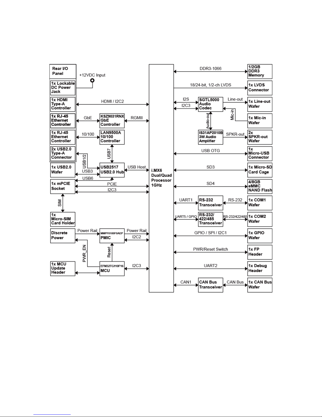
System Block Diagram
Figure 1 Block Diagr a m

Chapter 1
17
PITX-MX60 Series User’s Manual
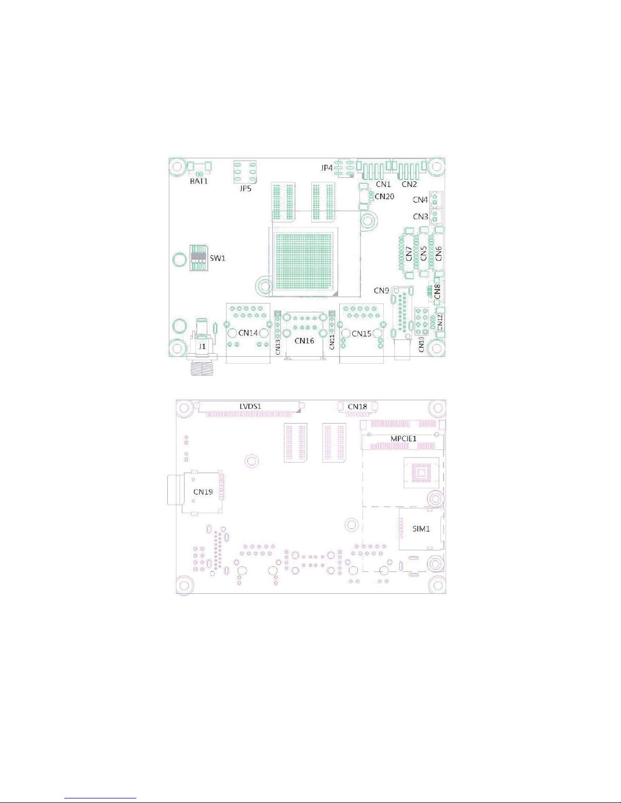
Mechanical Dimensions
Figure 2 Mechanical Dimensions

Chapter 2
18
PITX-MX60 Series User’s Manual
Chapter 2
Hardware Settings
Overview
This chapter provides the definitions and locations of jumpers, headers, and
connectors.
Jumpers
The product has several jumpers which must be properly configured to ensure
correct operation.
Figure 3 Jumper Connector
For a three-pin jumper (see Figure 3), the jumper setting is designated “1-2” when
the jumper connects pins 1 and 2. The jumper setting is designated “2-3” when pins
2 and 3 are connected and so on. You will see that one of the lines surrounding a
jumper pin is thick, which indicates pin No.1.
To move a jumper from one position to another, use needle-nose pliers or tweezers
to pull the pin cap off the pins and move it to the desired position.
Chapter 2
19
PITX-MX60 Series User’s Manual
Jumper Settings and Pin Definitions
For jumper and connector locations, please refer to the diagrams below.
Figure 4 Jumper and Connector Locations

Chapter 2
20
PITX-MX60 Series User’s Manual
Jumper Settings
To ensure correct system configuration, the following section describes how to set
the jumpers to enable/disable or change functions. For jumper descriptions, please
refer to the table below
.
Table 2 Jumper List
Label Function
JP4 Backlight Enable Selec tio n
JP5 Panel & Backlight Power Selec tion
SW1 Boot Device Selection
Table 3 JP4 Backlight Enable Selection
21
65
Jumper Setting Status
1
1-3 Backlight Enable Voltage = +3.3V
3-5 Backlight Enable Voltage = +5V
2
2-4 Backlight Enable High Active
4-6 Backlight Enable Low Active
Pitch: 2.0mm
Table 4 JP5 Backlight Power Selection
21
65
Jumper Setting Status
1
1-3 Backlight Power = +12V
3-5 Backlight Power = +5V
2
2-4 Panel Power = +3.3V
4-6 Panel Power = +5V
Pitch: 2.54mm
Table 5 SW1 Boot Device Selection
Switc h Number
Description
1 2 3 4
Off Off Off X Boot from Micro-SD Card
On On On X Boot from eMMC Flash

Chapter 2
21
PITX-MX60 Series User’s Manual
Internal Connector Pin Assignment
Table 6 Internal Connector Pin List
Label Function
BAT1 RTC Power Input Wafer
CN1 Micro-Phone Input Wafer
CN2 Head-Phone Output Wafer
CN3 Left Channel 3W Speaker Output Wafer
CN4 Right Channel 3W Speaker Output Wafer
CN5 COM2 RS-232/422/485 Wafer
CN6 COM1 RS-232 Wafer
CN7 GPIO/SPI/I2C Wafer
CN8 Micro USB2.0 OTG Connector
CN10 Front Panel Header
CN11 Debug Port Header
CN12 USB2.0 Wafer
CN13 MCU Update Header
CN18 Backlight Power Output Wafer
CN19 Micro-SD Card Cage
CN20 CAN Bus Wafer
LVDS1 18/24-bit, 1/2-channel LVDS Connector
MPCIE1 Full Size Mini-PCI Express Soc k et
SIM1 Micro SIM Card Holder
Table 7 BAT1 RTC Power Input Wafer
Pin Signal Name
1+VBAT
2GND
Pitch: 1.25mm
Table 8 CN1 Micro-Phone Input Wafer
Pin Signal Name
1MIC-In
2MIC-In
3GND
4Jack Detection
Pitch: 2.0mm
Table 9 CN2 Head-Phone Output Wafer
Pin Signal Name
1HP_R
2HP_L
3GND
4Jack Detection
Pitch: 2.0mm

Chapter 2
22
PITX-MX60 Series User’s Manual
Table 10 CN3 Left Channel 3W S pe aker Outp ut Wafer
Pin Signal Name
1 Speaker+
2 Speaker-
Pitch: 2.0mm
Table 11 CN4 Right Channel 3W Speaker Output Wafer
Pin Signal Name
1 Speaker+
2 Speaker-
Pitch: 2.0mm
Table 12 CN5 COM2 RS-232/422/485 Wa fer
Pin RS-232 RS-422
Half Duplex
RS-485
Full Deplex
RS-485
1 - TX- DATA- TX-
2- - - 3 RXD TX+ DATA+ TX+
4RTS - - 5 TXD RX+ - RX+
6CTS - - 7 - RX- - RX8- - - 9 GND GND GND GND
10 +5V +5V +5V +5V
Pitch: 1.25mm
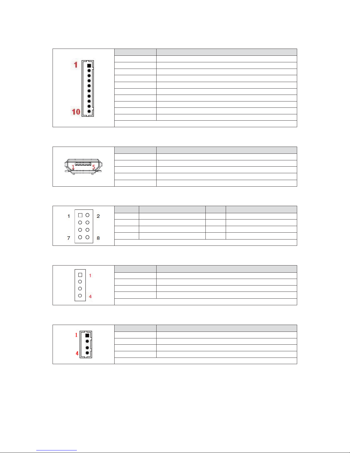
Table 13 CN6 COM1 RS-232 Wafer
Pin Pin Name
1 DCD
2DSR
3RXD
4RTS
5TXD
6CTS
7DTR
8RI
9GND
10 +5V
Pitch: 1.25mm
Chapter 2
23
PITX-MX60 Series User’s Manual
Table 14 CN7 GPIO/SPI/I2C Wafer
Pin Pin Name
1+5V
2GPIO1
3GPIO2
4 SPI1_CLK
5 SPI1_MOSI
6 SPI1_MISO
7 SPI1_SS0
8I2C1_SCL
9 I2C1_SDA
10 GND
Pitch: 1.25mm
Table 15 CN8 Micro USB2.0 OTG Connector
Pin Signal Name
1 VBUS
2D3D+
4ID
5GND
Table 16 CN10 Front Panel Header
Pin Signal Name Pin Signal Name
1 PWR_S/W+ 2 PWR_LED+
3 PWR_S/W- 4 PWR_LED5 SYS_RST+ 6 WWAN_LED+
7 SYS_RST- 8 WWAN_LED-
Pitch: 2.54mm
Table 17 CN1 1 Debug Port Header
Pin Signal Name
1 +3.3V
2 UART2_RXD
3UART2_TXD
4GND
Pitch: 2.0mm
Table 18 CN12 USB2.0 Wafer
Pin Signal Name
1 +USBVCC
2USB_D3USB_D+
4GND
Pitch: 1.25mm
Chapter 2
24
PITX-MX60 Series User’s Manual
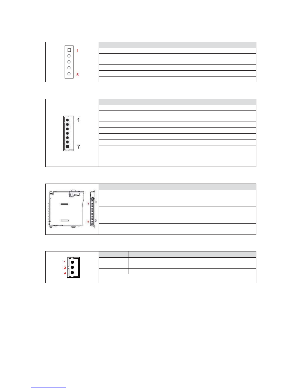
Table 19 CN13 MCU Update Header
Pin Signal Name
1+VMCU
2 RESETn
3SWDIO
4SWCLK
5GND
Pitch: 2.0mm
Table 20 CN18 Backlight Power Output Wafer
Pin Signal Name
1BL_PWN*
2NC
3GND
4 +5V / +12V**
5 +5V / +12V**
6GND
7BL_EN***
Pitch: 1.25mm
*: BL_PWM can be set by software.
**: Backlight Power can be selected b y JP5.
***: BL_EN can be set by JP4.
Table 21 CN19 Micro-SD Card Cage
Pin Signal Name
1DAT2
2 CD/DAT3
3CMD
4VDD
5CLK
6GND
7DAT0
8DAT1
Table 22 CN20 CAN Bus Wafer
Pin Signal
1CANH
2GND
3CANL
Pitch: 1.25mm

Chapter 2
25
PITX-MX60 Series User’s Manual
Table 23 LVDS1 18/24-bit, 1/2-channel LVDS Connector
Pin Signal Name Pin Signal Name
1 LVDS_A0- 16 LVDS_B1+
2 LVDS_A0+ 17 GND
3 LVDS_A1- 18 L VDS_B24 LVDS_A1+ 19 LVDS_B2+
5 LVDS_A2- 20 LVDSBCLK6 LVDS_A2+ 21 LVDS_BCLK+
7GND22LVDS_B38 LVDS_ACLK- 23 LVDS_B3+
9 L VDS_ACLK+ 24 GND
10 LVDS_A3- 25 NC
11 LVDS_A3+ 26 NC
12 LVDS_B0- 27 NC
13 LVDS_B0+ 28 +3.3V / +5V*
14 GND 29 +3.3V / +5V*
15 LVDS_B1- 30 +3.3V / +5V*
Pitch: 1.0mm [JAE FI-X30SSL-HF]
*: Panel Power can be selected by JP5.
Table 24 MPCIE1 Full Size Mini-PCI Express Socket
Signal Name Pin Pin Signal Name
WAKE# 1 2 +3.3V
-34GND
-56+1.5V
-78UIM_PWR**
GND 9 10 UIM_DATA**
REFCLK- 1 1 12 UIM_CLK**
REFCLK+ 13 14 UIM_RESET**
GND 15 16 UIM_VPP**
-1718GND
- 19 20 DISABLE#
GND 21 22 RESET#
PCIE_RX- 23 24 +3.3V
PCIE_RX+ 25 26 GND
GND 27 28 +1.5V
GND 29 30 I2C3_SCL
PCIE_TX- 31 32 I2C3_SDA
PCIE_TX+ 33 34 GND
GND 35 36 USB_D-
GND 37 38 USB_D+
+3.3V 39 40 GND
+3.3V 41 42 LED_WWAN
GND 43 44 -
-4546-
-4748+1.5V
-4950GND
-5151+3.3V
Height: 5.6mm
**: These pins are connected to SIM1 directly.

Chapter 2
26
PITX-MX60 Series User’s Manual
Table 25 SIM1 Micro SIM Card Holder
Pin Signal Name
C1 VCC
C2 GND
C3 RST
C4 VPP
C5 CLK
C6 IO

Chapter 2
27
PITX-MX60 Series User’s Manual
Rear Panel Pin Assignments
Figure 5 Rear Panel IO
Table 26 Rear Panel Connector List
Label Function
CN9 HDMI Connector
CN14 GbE RJ-45 Connector
CN15 10/100 RJ-45 Connector
CN16 Dual USB2.0 Type-A Connector
J1 +12VDC Power Input Jack
Table 27 CN9 HDMI Connector
Pin Signal Pin Signal
1 TMDS Data2+ 11 Ground
2 Ground 12 TMDS Clock3 TMDS Data2- 13 Reserved
4 TMDS Data1+ 14 Reserved
5 Ground 15 DDC_CLK
6 TMDS Data1- 16 DDC_DATA
7 TMDS Data0+ 17 Ground
8 Ground 18 +5 V Power
9 TMDS Data0- 19 Hot Plug Detect
10 TMDS Clock+
Table 28 CN14 GbE RJ-45 Connector
Pin Si gnal Name Pin Signal Name
1TX1+5TX32TX1-6TX23TX2+7TX4+
4TX3+8TX4-
Table 29 CN15 10/100 RJ-45 Connector
Pin Si gnal Name Pin Signal Name
1TX+5NC
2TX-6RX3RX+7 NC
4NC8NC

Chapter 2
28
PITX-MX60 Series User’s Manual
Table 30 CN16 Dual USB2.0 Type-AConnector
Pin Si gnal Name Pin Signal Name
1 +USBVCC* 5 +USBVCC*
2USB_A-6USB_B3 USB_A+ 7 USB_B+
4 GND 8 GND
Table 31 J1 +12VDC Power Input Jack
Ȝ2.5 mm, +12VDC Input
 Loading...