


SYSTEM 12
IBEW
1031
LU
y
9
AUDIO SPEC
S
Complete 2' x 2' class UL Listed Speaker System
Sealed and tuned enclosure, 25V/70V color coded leads
TILE REPLACEMENT LOUDSPEAKER ASSEMBLY
GENERAL DESCRIPTION
The SYSTEM 12 Series is a complete shallow depth, lightweight
loudspeaker assembly with an 8” O.D. loudspeaker with concentric
mount hard ber HF cone, multi-tap transformer, perforated steel
ba e and integral molded 1,411 CID ber enclosure. Cable clamp is
included; ve (5) seismic tie-o points. No assembly required.
Grille nish: Baked epoxy hybrid
SYSTEM COMPONENTS
Loudspeaker 8C5PAX
Transformer 25V/70V 5W-5 tap color coded leads
(5W, 2.5W, 1.25W, 0.63W, 0.31W)
MODELS GRILLE OPTIONS
SYSTEM 12 Standard Perf White
SYSTEM 12/B Standard Perf Black
SYSTEM 12/MP Micro-Perf White*
SYSTEM 12/MP/B Micro-Perf Black*
Standard Perf
Micro- Perf
AUDIO SPECIFICATIONS
Average Sensitivity 92 dB-SPL 1W/1M
Average Sensitivit
Loudspeaker Power Rating 12W-RMS EIA 426A Standard
Calculated Maximum
System Output
Magnet Type 4.8 oz. BeFe Ceramic
Frequency Response 65 Hz-17 kHz EIA 426A Standard
Nominal Coverage Angle
Audio Connection Pre-cut 7” color-coded leads
IFICATION
2 dB-SPL 1W/1M
99 dB-SPL 5W/1M
100° included angle -6 dB/ 2 kHz
half space
INTENDED USE
Indoor environment, mounted parallel to oor plane in a 24” wide suspended ceiling tile grid.
Program Material: Signal tones, voice and music.
UL Listed 1480- (UEAY, UEAY7- Canada)
As a General Signaling device- When installed with supplied
installation instructions and requirements of NEC /AHJ.
CITY of CHICAGO A PPROVED
Material and construction permits use where ceiling plenum is part
of the air handling system.
* These products have not been submitted to UL or City of Chicago
ACCESSORY
Kit #112 One 24” “T”-bar, white. Use with 2 ’x 2’ Tile
QUAM-NICHOLS COMPANY
234 East Marquette Road, Chicago IL 60637
Phone: (800) NEED NOW Fax: (888) NEED NOW
(800) 633-3669 (888) 633-3669
E-Mail: NeedNow@QNC.com www.QuamSpeakers.com
© 2012 Quam-Nichols Company, Quam- Nichols reserves the right to make changes and/or improvements to its products at any time and without notice. T0104.5-SYS12 12-SE01
Shown as 1" square samples
Recommended construction sequences, installation instructions and A&E Speci cations, EASE .GLL /.CFL data les are available
Replacement Loudspeaker in a 2’ x 4’ ceiling tile
in various formats in the QUAM Architects’ and Engineers’ Resources section on the web at: www.QuamSpeakers.com
.GLL / .CLF
DATA
91H1
Since 1930
8Ω
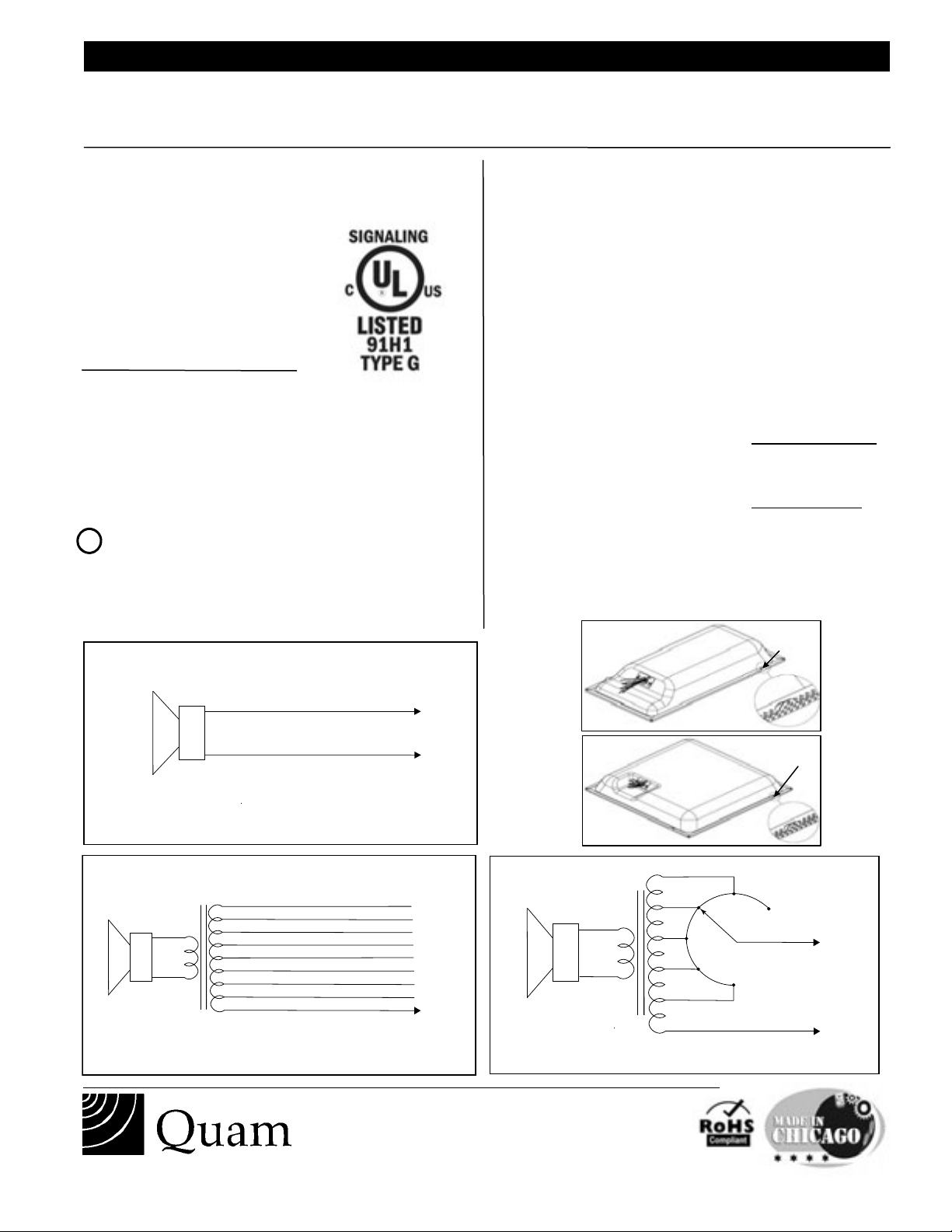
BLACK ( Common )
8Ω
QUAM 8-Ohm Operation
RED
BLACK ( Common )
8Ω
QUAM /25RS and /70RS Rotary Select
4W
0.25W
0.5W
1W
2W
OFF
RED
INSTALLATION INSTRUCTIONS
12– 9.4 8089
(1’ x 2’) SYSTEM 5 includes 8-Ohm, /25RS versions and /70RS versions
(2’ x 2’) SYSTEM 12 includes 8-Ohm, /25RS versions and /70RS versions, SYSTEM 19– includes 25RS and /70RS versions
INTENDED USE:
All versions: Indoor environment, mounted parallel to floor
plane in a 24” wide, suspended ceiling tile grid; mount height
18’ or less above floor plane.
Program material: Signal tones, voice and
music.
UL Listed 1480
City of Chicago Í Approved
“ Material and construction permits use
where ceiling plenum is part of the air
handling system”
Type G– General Signaling
1. Cut ceiling tile as required:
1’ x 2’ FORMAT LOUDSPEAKER
2’ x 2’ tile – Cut tile in half along one axis.
2’ x 4’ tile – Cut 12” from edge along 2’ axis and
discard smaller piece.
2’ x 2’ FORMAT LOUDSPEAKER
2’ x 2’ tile – No cutting required.
2’ x 4’ tile – Cut tile in half along 2’ axis.
! Steps 2-3 only– Required if using conduit clamp fitting
2. Loosen, but do not remove screws on cover plate;
push up and remove plate from assembly.
other than what is provided
with product
3. Remove cable /conduit clamp fitting from plate;
install UL Listed metallic enclosure entry fitting for
plenum cable or flex whip.
4. Feed supply cable through whip to connector.
Make connections per wiring diagrams lower left below;
insulate all unused taps from each other and enclosure.
When cover plate is secured, all connections / splices and
unused leads must be inside of the enclosure.
5. Place assembly onto ceiling grid, install 24” T-bar
trim piece where required (furnished only with specific
1’x2’ formats).
NOTE! AHJ/ local codes may require tie-off to structure.
Bend up tie-off tabs as shown in illustration and install as
directed.
NOTE! AHJ/ local codes may require tie-down to grid.
Recommended fasteners;
not supplied
: Erico/Caddy part
ATA4i and 1/4”-20 x 2” bolt, or equivalent. Install as
directed.
6. Place remaining ceiling tile into opening as required.
Tie-off
tab 2x
RED
8Ω
TIE OFF
BLACK ( Common )
QUAM 8-Ohm Operation
Brown 5W @ 25V only
Red 2.5W @ 25V only
Orange 1.25W @ 25V only
Green 0.63W @ 25V or 5W @ 70.7V
8Ω
© 2012 Quam-Nichols Company Quam-Nichols reserves the right to make changes and/or improvements to its products at any time and without notice.
White 0.32W @ 25V or 2.5W @ 70.7V
Blue only 1.25W @ 70.7V
Gray only 0.63W @ 70.7V
Violet only 0.32W @ 70.7V
BLACK ( Common )
QUAM Model TBLU
8Ω
QUAM /25RS and /70RS Rotary Select
234 East Marquette Road, Chicago, IL 60637
Phone: (800) NEED NOW Fax: (888) NEED NOW
(800) 633 - 3669 (888) 633 - 3669
E-Mail: neednow@qnc.com www.quamspeakers.com
TAB * 4
0.5W
1W
2W
BLACK ( Common )
0.25W
4W
Tie-off
tab 4x
OFF
RED
 Loading...