

Qualstar XLS-810240, XLS-810160 User Manual

‘
XLS-810160 & XLS-810240 Tape Libraries
Installation Manual
501801 Rev. A

Copyright© 2010 by Qualstar Corporation — All Rights Reserved
Information contained in this document is copyrighted by Qualstar Corporation. It is
intended for use by Qualstar's customers and prospective customers to evaluate,
integrate, operate, and maintain Qualstar products. Customers and prospective
customers may reproduce this document as needed for these uses. Reproduction in whole
or in part for any other use or by any other party is prohibited without prior written
permission from Qualstar Corporation.
Disclaimer
Every effort has been made to keep the information contained in this document current
and accurate as of the date of publication or revision. However, no guarantee is given or
implied that the document is error-free or that it is accurate with regard to any
specification.
Qualstar reserves the right to modify the design or specification without notice. This
specification may not be construed as a contractual obligation except as specifically
agreed to by Qualstar in writing at the time of order.
Trademark Notices
Qualstar and the Qualstar logo are registered trademarks and X-Link is a trademark of
Qualstar Corporation. Other trademarks are the property of their respective owners.
Revision History
Revision Release Date Description
A 02-Mar-2010 Initial release
ii 501801 Rev. A
Notices
Qualstar products are covered by one or more of the following patents: 6,271,982;
6,560,061; and 7,181,313. Other patents pending.
Qualstar equipment is manufactured from new parts, or new and used parts. In some
cases, Qualstar equipment may not be new and may have been previously installed.
Regardless, Qualstar’s warranty terms apply unless the equipment is specifically
identified by Qualstar as “used” or “refurbished.”
This equipment has been tested and found to comply with the limits for a Class A digital
device, pursuant to Part 15 of the FCC Rules. These limits are designed to provide
reasonable protection against harmful interference when the equipment is operated in a
commercial environment. This equipment generates, uses, and can radiate radio
frequency energy and, if not installed and used in accordance with the instruction
manual, may cause harmful interference to radio communications. Operation of this
equipment in a residential area is likely to cause harmful interference in which case the
user will be required to correct the interference at his own expense. Shielded cables are
required for this device to comply with FCC Rules. Use shielded cables when connecting
this device to others.
European Union Directive 89/336/EEC and Standard EN55022
(Electromagnetic Compatibility)
This product has been tested and is certified to be compliant with the Class A provisions
of the U.S., Canadian, and European standards for electromagnetic compatibility (EMC).
European Directive on Waste Electrical and Electronic Equipment (WEEE)
Qualstar encourages its customers to use current recycling practices in order
to reduce the burden that waste electronic products place on the environment.
If you are retiring a fully functional tape library, you are encouraged to
transfer the functional unit to a new user, thereby extending the useful life of
the tape library. The manufacture of all products requires the consumption of energy. By
extending the life of the tape library, energy is conserved.
In accordance with environmental directives that are being implemented in many
countries (refer to the European Directive on Waste Electrical and Electronic Equipment WEEE), Qualstar provides customers with
process for recycling the materials and components that make up a Qualstar tape library.
“End of Life Instructions” that identify the
End of Life Instructions
Tools required
• #1 and #2 Phillips screwdrivers
• T20 Torx head screwdriver
• Hex head (Allen) wrench/driver set
• 1/4-inch hex nut driver
XLS Library Installation Manual iii

Disassembly procedure
1. Remove the door(s).
2. Remove the front panel.
3. Remove the external side panels.
4. Remove the internal subassemblies.
Items recyclable using conventional methods
• Aluminum: Front panel, exterior side and rear panels, robotics, cartridge and drive bays,
carousel and shroud panels
• Stainless steel: Robot guides
• Steel: Frames, fasteners
• Plastic: Windows, cartridge magazines, tape cassettes
• Copper: Internal wiring, motors, SCSI cables
• Paper: Manuals
Items requiring special disposal due to lead-based solder
• Printed circuit boards: Controller card, miscellaneous small printed circuit boards
Items that may have salvage or resale value
• Tape drives
• EMI line power filter
Reduction of Hazardous Substances (RoHS)
Qualstar is committed to the implementation of RoHS (Restriction of the use of certain
hazardous substances in electrical and electronic equipment) in accordance with the
European Directive. The compliance date is July 1, 2006, at which time Qualstar will
certify that its tape library products are compliant with the RoHS standard.
Qualstar tape libraries are classified as “Information Technology Storage Array Systems”
for which the RoHS Directive provides an exemption for lead solder until the year 2010.
Until Qualstar replaces lead-based solder with lead-free solder, affected subassemblies
must be disposed of appropriately.
Technical Support
The best source for service-related information is your system reseller. Alternately, you
can reach the Qualstar Technical Support Department at:
Qualstar Corporation
Attn: Technical Support
3990-B Heritage Oak Court
Simi Valley, CA 93063
Monday - Friday 6:30 a.m. to 5:00 p.m. PST
Phone: (877) 444-1744
Phone: (805) 583-7744
After hours
Phone: (805) 526-7480
Phone: (805) 583-7748
E-mail: support@qualstar.com
E-mail: sales@qualstar.com
www.qualstar.com
iv 501801 Rev. A

Table of Contents
1 About This Manual . . . . . . . . . . . . . . . . . . . . . . . . . . . . . . . . . . . 1-1
1.1 About the XLS . . . . . . . . . . . . . . . . . . . . . . . . . . . . . . . . . . . . . . . . . . . . . . . . 1-1
1.2 Library Resource Module (LRM). . . . . . . . . . . . . . . . . . . . . . . . . . . . . . . . . . . 1-4
1.3 Media Expansion Module (MEM) . . . . . . . . . . . . . . . . . . . . . . . . . . . . . . . . . 1-16
1.4 How This Manual Is Organized . . . . . . . . . . . . . . . . . . . . . . . . . . . . . . . . . . 1-17
1.5 Conventions Used in This Manual . . . . . . . . . . . . . . . . . . . . . . . . . . . . . . . . 1-18
1.6 For More Information . . . . . . . . . . . . . . . . . . . . . . . . . . . . . . . . . . . . . . . . . 1-20
2 Preparing for Installation . . . . . . . . . . . . . . . . . . . . . . . . . . . . . . 2-1
2.1 Installation Overview . . . . . . . . . . . . . . . . . . . . . . . . . . . . . . . . . . . . . . . . . . . 2-2
2.2 Installation Check List . . . . . . . . . . . . . . . . . . . . . . . . . . . . . . . . . . . . . . . . . . 2-4
3 Unpacking the XLS . . . . . . . . . . . . . . . . . . . . . . . . . . . . . . . . . . . 3-1
3.1 Inspecting the Shipment . . . . . . . . . . . . . . . . . . . . . . . . . . . . . . . . . . . . . . . . 3-1
3.2 Unpacking the XLS . . . . . . . . . . . . . . . . . . . . . . . . . . . . . . . . . . . . . . . . . . . . 3-3
4 Installing the LRM. . . . . . . . . . . . . . . . . . . . . . . . . . . . . . . . . . . . 4-1
4.1 Extending the Leveling Feet . . . . . . . . . . . . . . . . . . . . . . . . . . . . . . . . . . . . . . 4-1
5 Installing a MEM . . . . . . . . . . . . . . . . . . . . . . . . . . . . . . . . . . . . . 5-1
5.1 Preparing the LRM. . . . . . . . . . . . . . . . . . . . . . . . . . . . . . . . . . . . . . . . . . . . . 5-1
5.2 Removing the X-Axis Hard Stop . . . . . . . . . . . . . . . . . . . . . . . . . . . . . . . . . . . 5-3
5.3 Releasing the Carousel Locks in a XLS-85000 MEM . . . . . . . . . . . . . . . . . . . . 5-4
5.4 Connecting the Carousel Controller Cable . . . . . . . . . . . . . . . . . . . . . . . . . . . 5-6
5.5 Attaching the LRM to the MEM . . . . . . . . . . . . . . . . . . . . . . . . . . . . . . . . . . . 5-8
5.6 Lowering the Leveling Feet . . . . . . . . . . . . . . . . . . . . . . . . . . . . . . . . . . . . . . 5-9
5.7 Installing the Side Panel on the MEM . . . . . . . . . . . . . . . . . . . . . . . . . . . . . . 5-11
XLS Library Installation Manual v

Table of Contents
6 Installing an Expansion Pod . . . . . . . . . . . . . . . . . . . . . . . . . . . . 6-1
6.1 Removing the Left Side Panel from the XLS-810160/810240 . . . . . . . . . . . . . 6-2
6.2 Installing the Expansion Pod Mounting Hardware. . . . . . . . . . . . . . . . . . . . . . 6-3
6.3 Removing the X-Axis Hard Stop . . . . . . . . . . . . . . . . . . . . . . . . . . . . . . . . . . . 6-7
6.4 Attaching the Expansion Pod to the XLS-810160/810240. . . . . . . . . . . . . . . . 6-8
6.5 Installing the Rear Side Panel . . . . . . . . . . . . . . . . . . . . . . . . . . . . . . . . . . . . 6-11
7 Installing the Tape Drive Assemblies . . . . . . . . . . . . . . . . . . . . . 7-1
7.1 Before You Begin. . . . . . . . . . . . . . . . . . . . . . . . . . . . . . . . . . . . . . . . . . . . . . 7-2
7.2 Installing Tape Drive and Drive Filler Assemblies . . . . . . . . . . . . . . . . . . . . . 7-12
8 Connecting the XLS. . . . . . . . . . . . . . . . . . . . . . . . . . . . . . . . . . . 8-1
8.1 Before You Begin. . . . . . . . . . . . . . . . . . . . . . . . . . . . . . . . . . . . . . . . . . . . . . 8-1
8.2 Connecting the Cables. . . . . . . . . . . . . . . . . . . . . . . . . . . . . . . . . . . . . . . . . . 8-1
9 Applying Power and Logging Into X-Link . . . . . . . . . . . . . . . . . . 9-1
9.1 Preparing to Power on the Library . . . . . . . . . . . . . . . . . . . . . . . . . . . . . . . . . 9-1
9.2 Connecting the Library to Power . . . . . . . . . . . . . . . . . . . . . . . . . . . . . . . . . . 9-3
9.3 Logging Into X-Link . . . . . . . . . . . . . . . . . . . . . . . . . . . . . . . . . . . . . . . . . . . 9-11
10 Configuring the Physical Library. . . . . . . . . . . . . . . . . . . . . . . 10-1
10.1 Connecting the XLS to a Computer . . . . . . . . . . . . . . . . . . . . . . . . . . . . . . . 10-1
10.2 Aligning the Gripper with a MEM. . . . . . . . . . . . . . . . . . . . . . . . . . . . . . . . . 10-4
10.3 Calibrating an Expansion Pod Equipped Library . . . . . . . . . . . . . . . . . . . . . . 10-9
10.4 Verifying the Hardware Configuration . . . . . . . . . . . . . . . . . . . . . . . . . . . . 10-19
10.5 Entering Configuration Information . . . . . . . . . . . . . . . . . . . . . . . . . . . . . . 10-22
10.6 Defining Other Library Settings and Policies. . . . . . . . . . . . . . . . . . . . . . . . 10-33
11 Setting Up Logical Libraries . . . . . . . . . . . . . . . . . . . . . . . . . . 11-1
11.1 About Physical and Logical Libraries. . . . . . . . . . . . . . . . . . . . . . . . . . . . . . . 11-1
11.2 Creating a New Logical Library . . . . . . . . . . . . . . . . . . . . . . . . . . . . . . . . . . 11-3
11.3 Viewing the Inventory Report. . . . . . . . . . . . . . . . . . . . . . . . . . . . . . . . . . . 11-11
12 Loading Cartridges . . . . . . . . . . . . . . . . . . . . . . . . . . . . . . . . . 12-1
12.1 Installing Cartridges in the Reserved Slots . . . . . . . . . . . . . . . . . . . . . . . . . . . 12-1
vi 501801 Rev. A

Table of Contents
12.2 Precautions for Handling Cartridges . . . . . . . . . . . . . . . . . . . . . . . . . . . . . . . 12-3
12.3 Preparing Cartridges . . . . . . . . . . . . . . . . . . . . . . . . . . . . . . . . . . . . . . . . . . 12-4
12.4 Installing Cartridges in Cartridge Slots. . . . . . . . . . . . . . . . . . . . . . . . . . . . . . 12-5
13 Scanning the Fiducials and Inventory. . . . . . . . . . . . . . . . . . . 13-1
13.1 Before You Begin. . . . . . . . . . . . . . . . . . . . . . . . . . . . . . . . . . . . . . . . . . . . . 13-1
13.2 Scanning and Calibrating the Fiducials . . . . . . . . . . . . . . . . . . . . . . . . . . . . . 13-2
13.3 Scanning the Inventory and Locking the Doors. . . . . . . . . . . . . . . . . . . . . . . 13-7
14 Testing the Installation . . . . . . . . . . . . . . . . . . . . . . . . . . . . . . 14-1
14.1 Putting the XLS in Logical Mode. . . . . . . . . . . . . . . . . . . . . . . . . . . . . . . . . . 14-1
14.2 Bringing a Logical Library Online . . . . . . . . . . . . . . . . . . . . . . . . . . . . . . . . . 14-2
14.3 Starting the Application . . . . . . . . . . . . . . . . . . . . . . . . . . . . . . . . . . . . . . . . 14-3
14.4 Troubleshooting Installation Problems . . . . . . . . . . . . . . . . . . . . . . . . . . . . . 14-4
14.5 Downloading the Library Configuration . . . . . . . . . . . . . . . . . . . . . . . . . . . . 14-5
Appendix A Library Addresses . . . . . . . . . . . . . . . . . . . . . . . . . . . . A-1
A.1 Addresses for the XLS-810160/810240 . . . . . . . . . . . . . . . . . . . . . . . . . . . . . A-2
A.2 Addresses for Expansion Pod, I/O Ports, and Fixed Port Slots . . . . . . . . . . . . . A-5
A.3 Addresses for the Media Expansion Module (MEM) . . . . . . . . . . . . . . . . . . . . A-7
Glossary . . . . . . . . . . . . . . . . . . . . . . . . . . . . . . . . . . . . . . . . . . . . . GL-1
Index. . . . . . . . . . . . . . . . . . . . . . . . . . . . . . . . . . . . . . . . . . . . . . . . IN-1
XLS Library Installation Manual vii

Table of Contents
viii 501801 Rev. A

1 About This Manual
This manual is intended for anyone installing the Qualstar® XLS Library. It provides
instructions for completing XLS installation and configuration.
Important: Although Qualstar has made every effort to ensure the
accuracy of the information contained in this manual,
no guarantee is expressed or implied that the manual is
error free. Qualstar reserves the right to make changes
at any time without prior notification.
1.1 About the XLS
The Qualstar XLS Enterprise Tape Library contains large-capacity tape drives, a variable
number of cartridge storage slots, a high-speed robotic mechanism for moving cartridges
between the tape drives and the storage slots, and I/O ports for importing and exporting
cartridges from the library. Six XLS models are currently available—the XLS-8161100,
XLS-832700, the XLS-820500, XLS-812300, and the XLS-810160/810240. This manual
will focus on the XLS-810160 and XLS-810240 models.
Shown in Figure 1-1 on page 1-2
• The Library Resource Module (LRM), described in Section 1.2 on page 1-4
the fully featured base cabinet containing the power system; the robotic handler;
the control electronics; and the tape drives, I/O ports, and cartridge slots.
• The optional Media Expansion Modules (MEM), described in Section 1.3 on
page 1-16, is a rotary tape carousel that attaches to the left side of an LRM.
, the library uses two building blocks:
, is
XLS Library Installation Manual 1-1

1.1 About the XLS
• The XLS-85000 (also referred to as a MEM2) contains 517 cartridges.
Figure 1-1 LRM with one MEM2
1-2 501801 Rev. A
1 About This Manual
Touch screen
Status LEDs
I/O ports
(up to 2)
Wheels (4)
Leveling feet (4)
Tape drives
Carousels
Door
(on side of LRM)
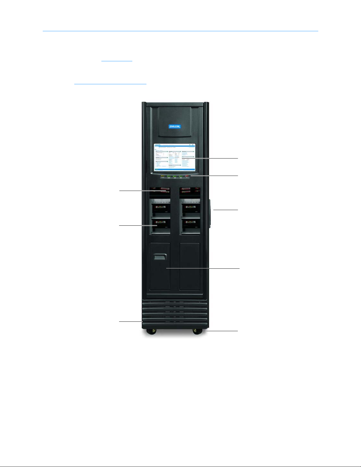
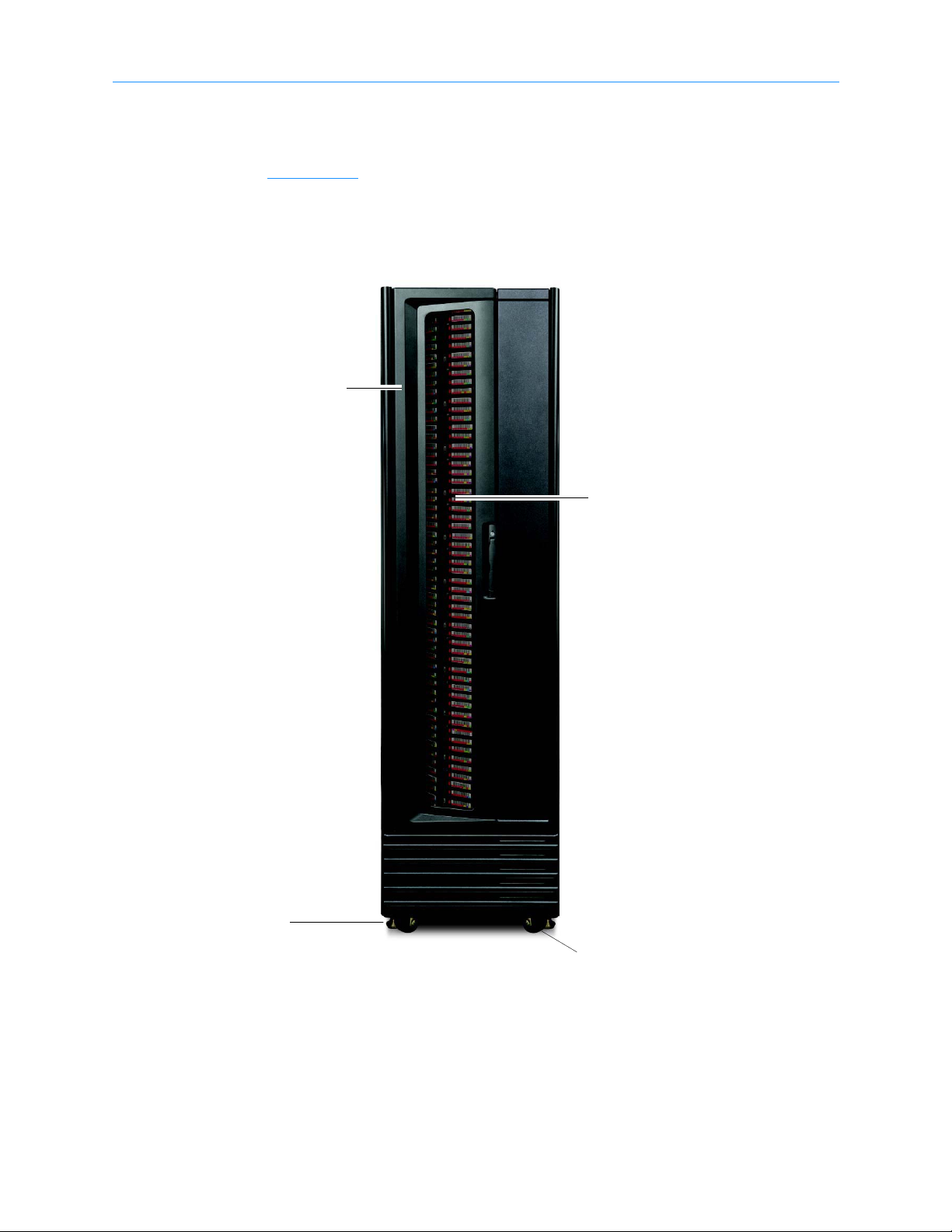
1.1.1 XLS-810160/810240
Shown in Figure 1-2, the XLS-810160/810240 accommodates up to 10 tape drives, up to
245 cartridges, and up to two, 10-slot I/O ports. As an option, one Media Expansion
Modules (MEM) can be installed on the left side of the XLS-810160/810240. See
Section 1.3 on page 1-16
for more information.
Figure 1-2 Front view of the XLS-810160/810240
XLS Library Installation Manual 1-3
1.2 Library Resource Module (LRM)
I/O ports
(10 slots/port)
Handler
Door
(on side of LRM)
Drive bay
(2 drives/bay)
Carousel
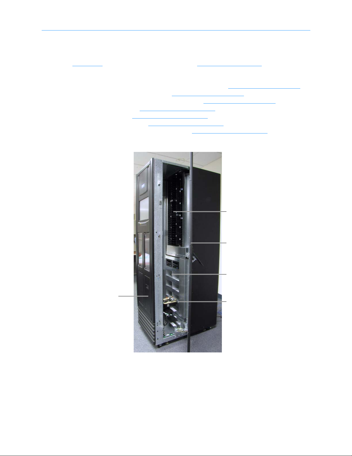
1.2 Library Resource Module (LRM)
Figure 1-3 shows the inside of the LRM, while Figure 1-4 on page 1-5 shows the back of
the LRM. The LRM contains the following components and features:
• PC bay, which includes the system controller (see Section 1.2.1 on page 1-5
• Touch screen and LEDs (see Section 1.2.2 on page 1-8
• Robotic handler and barcode reader (see Section 1.2.3 on page 1-9
• Tape drives (see Section 1.2.4 on page 1-12
• I/O ports (see Section 1.2.5 on page 1-14
• Cartridge slots (see Section 1.2.6 on page 1-15
• Doors and light curtain sensors (see Section 1.2.7 on page 1-15
)
)
)
)
)
)
)
Figure 1-3 Inside view of the LRM
1-4 501801 Rev. A
1 About This Manual
Power supplies
(up to 3)
PC bay
Drive bay
(2 drives/bay)
Battery module
Power connector
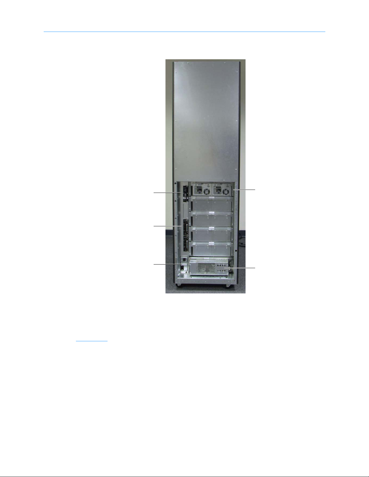
Figure 1-4 Rear view of the LRM
1.2.1 PC Bay
Figure 1-4 shows the location of the PC bay at the rear of the LRM. The PC bay houses
the system controller and slides in and out of the LRM for servicing.
XLS Library Installation Manual 1-5

1.2 Library Resource Module (LRM)
Power supplies
(up to 3)
Battery module
Power connector
Power switch/
breaker
Filler plate
Power System
Figure 1-5 shows the power components accessible from the rear of the LRM. An optional
redundant power input module is also avaivable.
Figure 1-5 Power components
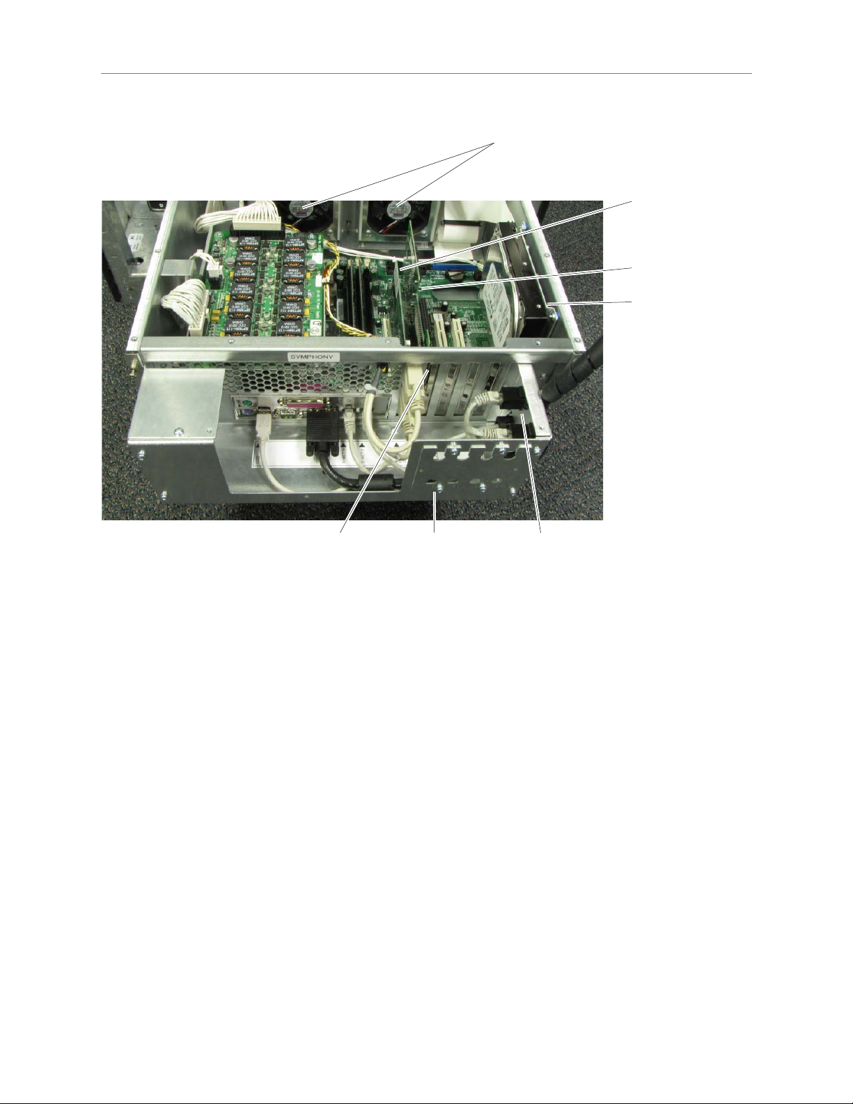
System Controller
Shown in Figure 1-6 on page 1-7, the system controller consists of a Linux-based
computer that controls the library. The system controller:
• Controls the operation of the distributed control boards (DCBs)
• Manages all communications between the XLS and the host applications
• Maintains an up-to-date cartridge inventory
• Hosts the X-Link management interface
• Provides a control interface to the tape drives for configuration and servicing
1-6 501801 Rev. A
1 About This Manual
Serial & Ethernet
connectors
HBA connectors
Host Bus Adapter
cards
Cooling fans
EMI shield
CAN bus
controller
Hard drive
Figure 1-6 System controller components in the PC bay
XLS Library Installation Manual 1-7
1.2 Library Resource Module (LRM)
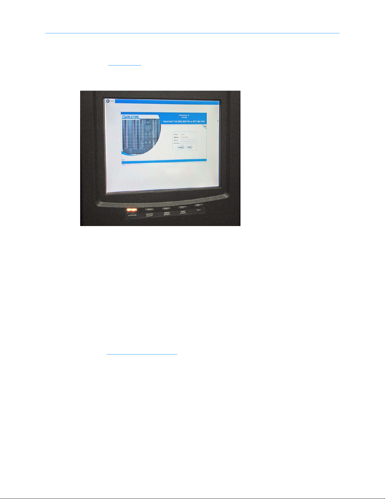
1.2.2 Touch Screen and LEDs
Shown in Figure 1-7, each LRM includes a touch screen, used to display the X-Link
Management Interface, and five LEDs.
Figure 1-7 Touch screen and status LEDs (X-Link log-in screen displayed)
Touch Screen
The 15-inch LCD touch screen on the front of the LRM allows for local control and
monitoring of library operations. The touch screen receives power from the PC power
supply in the system controller and communicates with the system controller using a USB
interface.
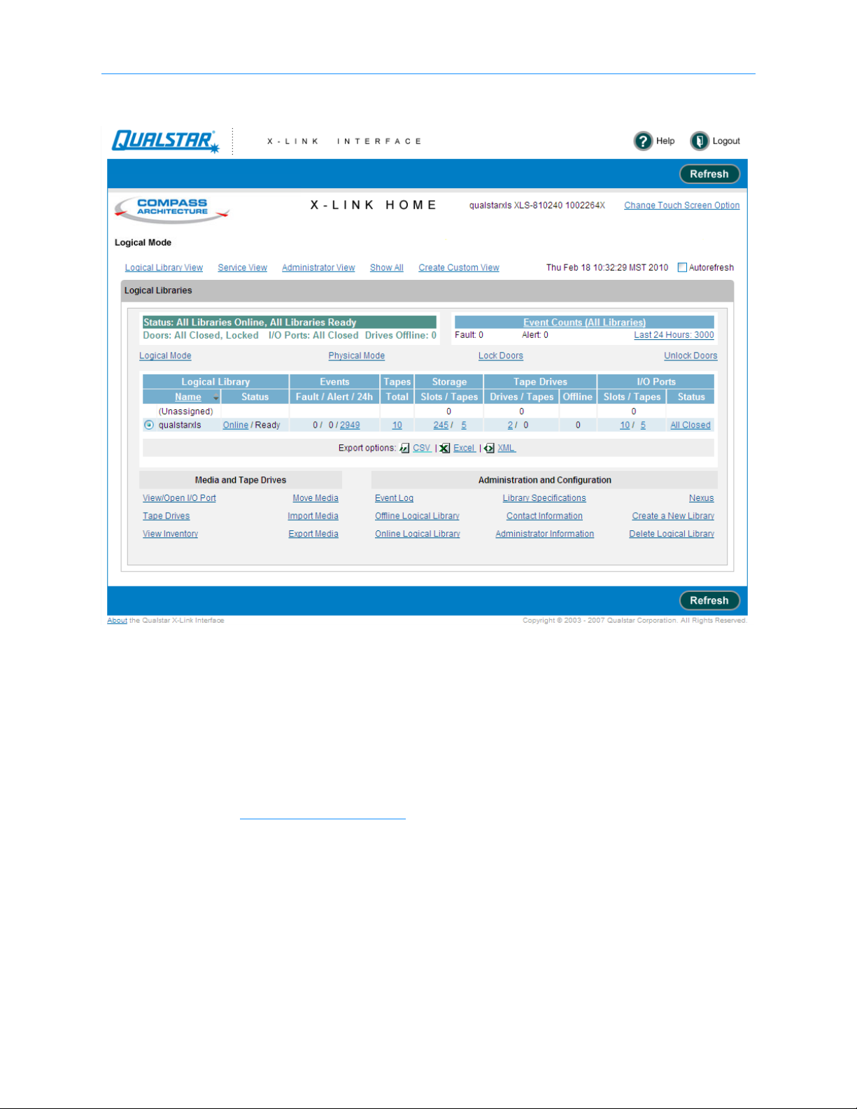
X-Link Management Interface
The X-Link management interface can be accessed locally from the touch screen or
remotely over Ethernet using a standard Internet browser. The interface and available
functions are the same regardless of how they are accessed. The X-Link Home page,
shown in Figure 1-8 on page 1-9
an access point to library management tasks.
, provides information about library status and provides
1-8 501801 Rev. A
1 About This Manual
Figure 1-8 X-link Home page (Logical Libraries View selected)
LEDs
The LEDs on the front panel indicate the library's operational status at a glance. Status
LEDs are also included on the back of each tape drive assembly and each power supply.
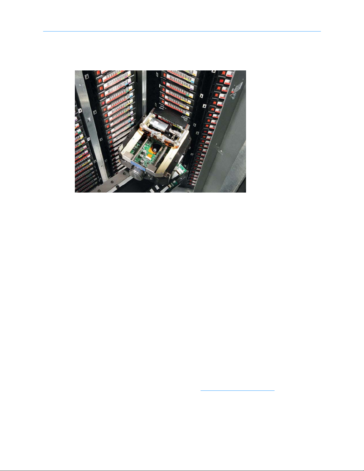
1.2.3 Robotic Handler and Barcode Reader
Shown in Figure 1-9 on page 1-10, the robotic tape handler within each LRM can access
cartridges anywhere on the front wall or the rotating carousel. It can also access slots on
XLS Library Installation Manual 1-9
1.2 Library Resource Module (LRM)
the carousel of an attached MEM. The handler is controlled by the medium changer
interface and shared by all host software applications on a first-come, first-served basis.
Figure 1-9 Robotic handler (shown reaching into an attached MEM)
Gripper Assembly
The gripper assembly is the part of the handler that actually picks and places the
cartridges in the storage slots and tape drives. The gripper moves along four axes, as
follows:
• The X-axis is the horizontal axis.
• The Y-axis is the vertical axis.
• The Theta-axis is the rotating axis that allows the gripper assembly to reach
cartridge slots on the front, back, and sides of the cabinet.
• The Z-axis is the in-and-out axis. The fingers on the gripper assembly are opened
and closed using a solenoid and use a sensor to determine if they are open or
closed.
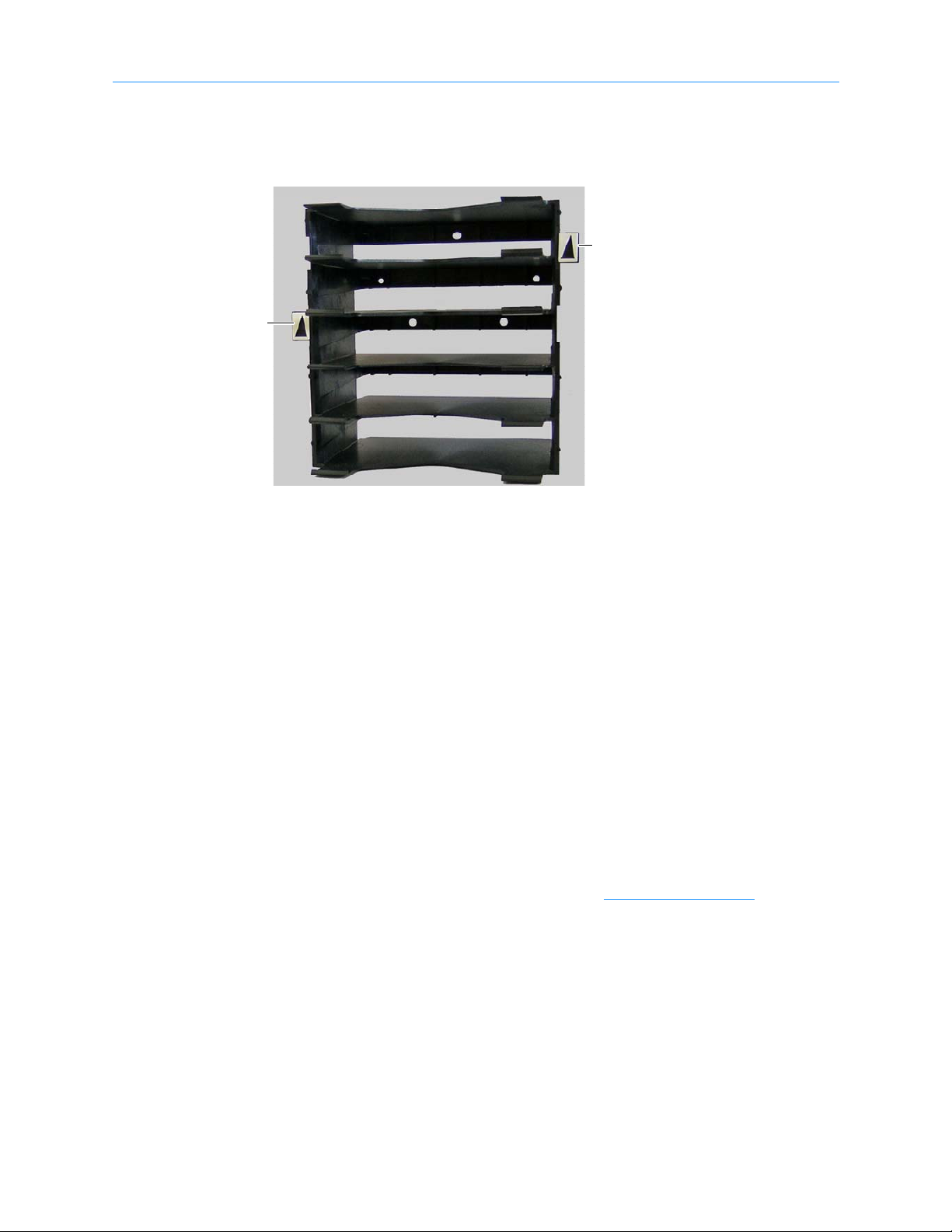
Barcode Reader
Located on the gripper assembly, the barcode reader performs two types of scans:
• Fiducial scan. Fiducials are the black and white triangles mounted on either
side of every cartridge magazine (see Figure 1-10 on page 1-11
1-10 501801 Rev. A
). There is also a
fiducial located on the tape drive calibration cartridge, which is stored in one of
Fiducial
Fiducial
the five reserved slots.
Figure 1-10 Cartridge magazine with two fiducials
1 About This Manual
During a fiducial scan, the handler moves up and down and across the cartridge
slots and I/O ports until the barcode reader detects the fiducials. It also inserts
the calibration cartridge into each tape drive. Once all the fiducials have been
detected, the library can calculate the exact position of every storage slot and
tape drive in a process known as calibration. Fidicual scans and calibration are
required only when the library is installed or when certain service procedures are
performed.
• Inventory scan. During an inventory scan, the barcode reader scans each slot to
determine which ones contain cartridges. It also scans the barcode labels on the
cartridges to establish and maintain its cartridge inventory. The system
controller stores the cartridge inventory in a database and makes it available to
the host applications.
Barcode labels must conform to the ANSI/AIM BCI-1995, Uniform Symbol
Specification (USS-39). Detailed specifications for XLS barcodes and labels can
be found in Qualstar Product Information Note 040, “XLS, RLS, and TLS
Barcode Labels.” To obtain this document, go to www.qualstar.com
on the Support tab. Pre-printed barcode labels, which are both human- and
machine-readable, are available from a number of sources.
and click
XLS Library Installation Manual 1-11
1.2 Library Resource Module (LRM)
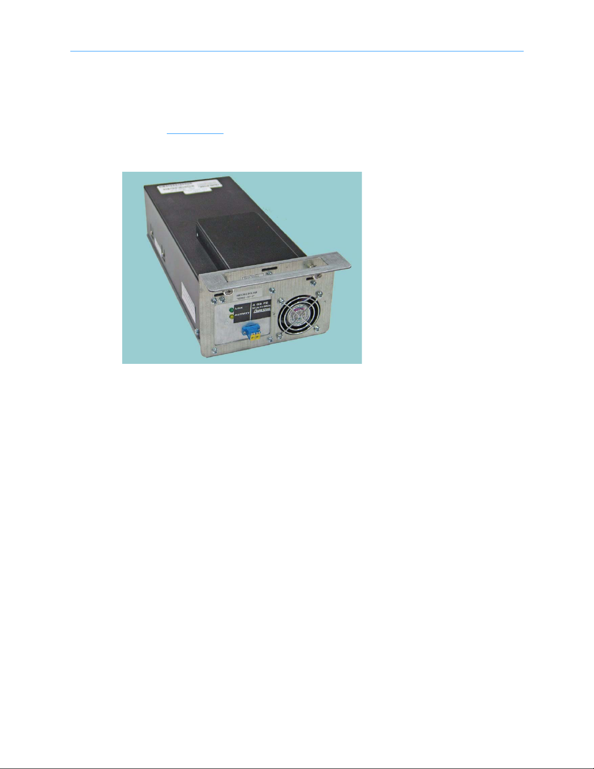
1.2.4 Tape Drives
Tape Drive Assemblies
Shown in Figure 1-11, an XLS tape drive assembly consists of an LTO tape drive
enclosed in a drive carrier.
Figure 1-11 Fibre Channel tape drive assembly (rear view)
Two models of tape drives are available: SCSI tape drive assemblies include dual SCSI
HD68 connectors and a single status LED, while Fibre Channel tape drive assemblies
include a duplex LC multi-mode Fibre Channel receptacle and three LEDs.
Depending on the capabilities of the application software being used, the Fibre Channel
tape drive assemblies can be removed and replaced without powering down the library.
The library automatically detects the presence of a new tape drive.
1-12 501801 Rev. A
1 About This Manual
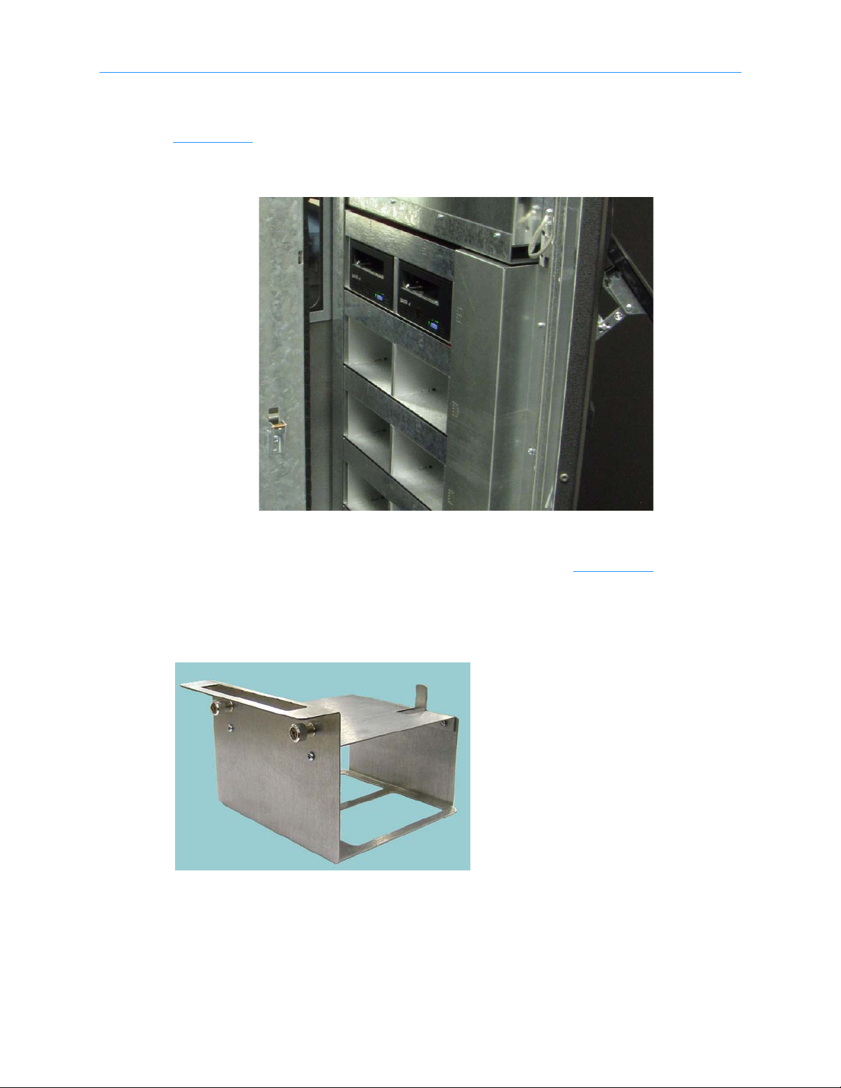
Drive Bays
Figure 1-12 shows the view of several drive bays through the open door. Each drive bay
can hold up to two tape drive assemblies, which are installed from the rear of the LRM.
Figure 1-12 View of drive bays throughthe open door
For safety reasons, all tape drive or drive filler assemblies (see Figure 1-13
installed in each drive bay in order for the library to operate. If the library detects that
one of the positions is empty, it disables the handler until another tape drive or drive filler
assembly is installed.
Figure 1-13 Drive filler assembly
) must be
XLS Library Installation Manual 1-13
1.2 Library Resource Module (LRM)
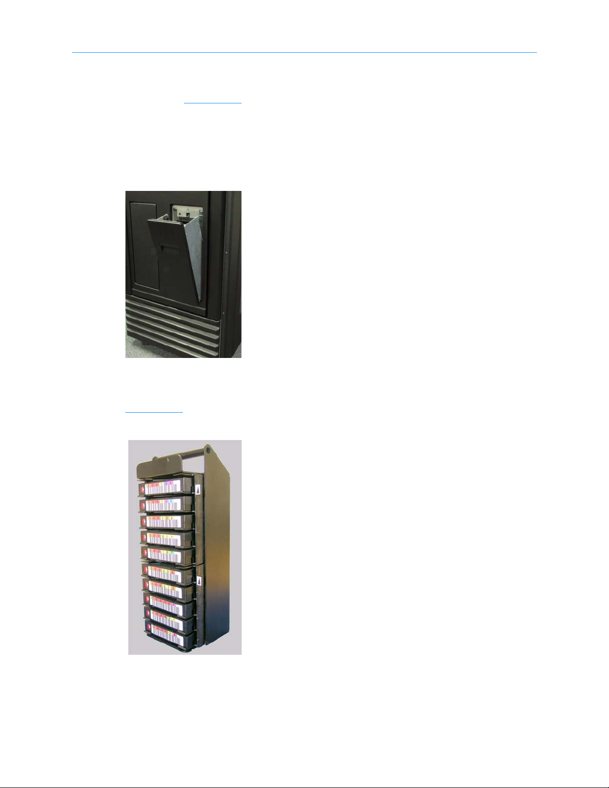
1.2.5 I/O Ports
As shown in Figure 1-14, I/O ports on the front of the LRM allow cartridges to be
imported or exported without opening the door(s) and interrupting XLS operations. Each
I/O port holds 10 cartridges in a removable magazine. Depending on the model, the XLS
can include one or two I/O ports. For each I/O port that is not installed, the library
includes 10 additional cartridge storage slots, called fixed port assemblies.
Figure 1-14 I/O port
Each I/O port uses a removable magazine suitable for long-term storage. See
Figure 1-15
.
Figure 1-15 I/O port magazine
1-14 501801 Rev. A
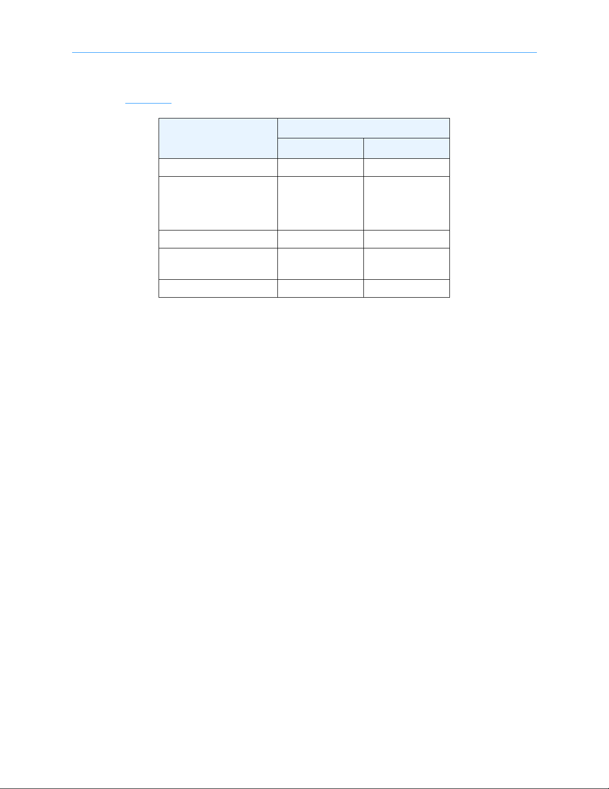
1.2.6 Cartridge Slots
Table 1-1 lists the cartridge capacities of each XLS model.
Number of Cartridge Slots
Location
XLS-810160 XLS-810240
Carousel slots 155 235
1 About This Manual
up to 10
Fixed port slots
Total slots up to 165 up to 245
MEM2 adds
Expansion pod adds 116 116
Tab le 1 - 1 Available cartridge slots
(assumes only one
I/O port is
installed)
XLS-85000
adds 517
up to 10
(assumes only one
I/O port is
installed)
XLS-85000
adds 517
1.2.7 Door and Light Curtain Sensors
Door
The XLS-810160 and XLS-810240 have a single door on the right side. The XLS-85000
MEM2 has a single door that opens on the front. All doors have windows for viewing robot
operations and the LRM’s have front windows. There are also viewing windows on the
side panels.
Light Curtain Assembly
The light curtain, also known as the “Inventory Sentry,” consists of a series of infrared
emitters and detectors arrayed throughout the XLS. The emitters project small beams of
infrared light that is not visible to the naked eye toward corresponding detectors.
The curtain of light formed by the emitters and detectors allows the XLS to precisely
monitor all areas within the LRM and MEM cabinets, as follows:
• The beams of light at the rear of the cabinet can detect whether a cartridge is
protruding from a slot. If the door is closed and one of these beams of light is
broken, the XLS prevents the handler from moving to avoid hitting a protruding
cartridge.
• The beams of light curtain at the front of the cabinet can detect when someone
reaches into the cabinet. If the door is open and one of these beams of light is
broken, the XLS detects and logs a potential inventory violation and
automatically scans the cartridges and drives in the affected area as soon as the
door is closed.
XLS Library Installation Manual 1-15
1.3 Media Expansion Module (MEM)
Door
Leveling feet (4)
Wheels (4)
Carousel
1.3 Media Expansion Module (MEM)
Shown in Figure 1-16 the Media Expansion Module (MEM) includes a rotating
motor-driven carousel containing cartridge slots. The XLS-85000 (MEM2) can store up to
517 cartridges. The XLS-810160/810240 can be expanded by adding one XLS-85000 MEM
to its left side.
Figure 1-16 Front view of an XLS-85000 Media Expansion Module (MEM2)
A MEM derives its power and control from an attached LRM. The carousel can rotate in
either direction and the handler from an attached LRM can reach into a MEM to pick,
place, and scan the barcode of any cartridge.
1-16 501801 Rev. A
1.4 How This Manual Is Organized
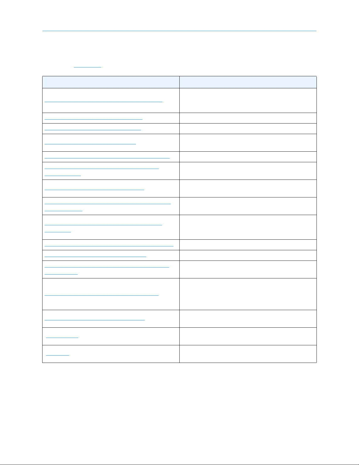
Table 1-2 is a quick reference for locating the information in this manual.
Refer to... For...
Overview of the installation process, including a
Chapter 2, “Preparing for Installation”
check list of required and optional components and
accessories
1 About This Manual
Chapter 3, “
Chapter 4, “
Chapter 5, “
Chapter 6, “
Chapter 7, “
Assemblies”
Chapter 8, “
Chapter 9, “
Into X-Link”
Chapter 10, “
Library”
Chapter 11, “
Chapter 12, “
Chapter 13, “
Inventory”
Chapter 14, “
Unpacking the XLS” Instructions for unpacking the XLS and its components
Installing the LRM” Instructions for setting up the LRM
Installing a MEM”
Installing an Expansion Pod” Instructions for attaching an expansion pod (optional)
Installing the Tape Drive
Connecting the XLS”
Applying Power and Logging
Configuring the Physical
Setting Up Logical Libraries” Instructions for creating logical libraries from X-Link
Loading Cartridges” Instructions for loading cartridges into the XLS
Scanning the Fiducials and
Testing the Installation”
Instructions for attaching a MEM2 to the LRM
(optional)
Instructions for installing tape drives in the LRM
Instructions for connecting the XLS and tape drives to
SCSI or Fibre Channel host computers
Instructions for performing the initial power on and
logging into X-Link from the touch screen
Instructions for setting up the physical library,
including information about connecting the XLS to a
standalone computer or Ethernet network
Instructions for scanning the fiducials and cartridge
inventory
Instructions for bringing the logical libraries online and
testing the software applications to ensure that all
components are working and communicating
correctly
Appendix A, “
“
Glossary”
“
Index”
Tab le 1 - 2 Information included in the XLS Library Installation Manual
XLS Library Installation Manual 1-17
Library Addresses”
Graphics showing the physical addresses for all
cartridge slot and tape drive locations
Definitions of the specialized terminology used in this
manual
Alphabetized quick reference for specific topics and
terms

1.5 Conventions Used in This Manual
1.5 Conventions Used in This Manual
This section lists the terminology, typographic, and organizational conventions used in
this manual.
1.5.1 Terminology
For clarity and compliance with the SCSI standard, the library control interface of the
XLS is referred to as the medium changer. Note that the medium changer is different
than the handler, which is simply the robotic mechanism within the XLS that picks and
places the cartridges.
Refer to the “
Glossary” for the definitions of other specialized terminology.
1.5.2 Typographic Conventions
This manual uses the following typographic conventions:
• For X-Link, options that can be selected are shown in bold face. For example:
– Select Online Logical Library
• For X-Link, names of buttons that can be pressed are shown in bold face. For
example:
– Press Done
–Press Unlock Doors
• For X-Link, names of fields or drop-down lists are shown in bold face. For
example:
– Column and Row drop-down lists
• Specialized terminology is introduced in italic face. For example:
– Each physical library can be partitioned into one or more logical libraries.
1-18 501801 Rev. A

1 About This Manual
1.5.3 Safety Notices
This manual may include four types of notices.
Warnings and Caution Notices
To avoid personal injury, damage to the equipment, or loss of data, closely follow the
operating instructions and maintenance procedures described in this manual. Pay special
attention to the information in Warning and Caution notices, as described below:
WARNING!
Personal injury may result if you do not fully comply with the handling,
operating, or service instructions found in a Warning notice.
CAUTION
Equipment damage or loss of data may result if you do not fully comply
with the handling, operating, or service instructions found in a Caution
notice.
Important Notices and Notes
Important notices and notes provide additional information and tips, as described below:
Important: Important notices provide tips for completing a
procedure or information that is essential to the
understanding of a topic.
Note: Notes provide additional information related to the topic being discussed.
XLS Library Installation Manual 1-19

1.6 For More Information
1.6 For More Information
This section provides information about related manuals and how to contact Qualstar.
1.6.1 Related Manuals
For more information about the XLS library, refer to the manuals in Table 1-3, which can
be downloaded onto any computer connected to the XLS. The manuals are in Adobe
Acrobat PDF format.
Refer to... Part number For...
XLS-810160/810240 Tape Library
Product Specification
XLS-810160/810240 Tape Library
Site Planning Guide
XLS-810160/810240 Tape Library
User’s Guide
XLS Library Interface Manual 501611
XLS-810160/810240 Tape Library
Technical Service Manual
Tab le 1 - 3 Related manuals
501800 Specifications for the XLS-810160 and XLS-810240
501804
501803 Instructions for operating the XLS-810160/810240
501810
Information for preparing a site for
XLS-810160/810240 installation
Information software developers need to control the
XLS using a software application
Information authorized service personnel need to
maintain the XLS and replace XLS components
Note: The Qualstar XLS Library is a sophisticated,
state-of-the art computer peripheral. It must
be serviced by authorized service technicians
who are experienced with the operation and
maintenance of tape libraries and who have
read and understood the XLS-810160/810240
Tape Library Technical Service Manual.
1.6.2 Accessing the Online Manuals
Important: You cannot access the online manuals from the touch
screen. To access the PDF files for the manuals, you
must connect the XLS to a standalone or networked
computer that has Adobe Acrobat or Adobe Reader
installed.
To access and download the manuals, follow these steps:
1. Follow the instructions in Section 10.1 on page 10-1
standalone computer or Ethernet network.
2. Open any of the supported Internet browsers on an attached computer.
1-20 501801 Rev. A
to connect the library to a

3. In the address field for the browser, type
http://qualstarxls/manuals/index.html, where qualstarxls is the default name
for the physical library. See Figure 1-17
Figure 1-17 Accessing the online manuals (Internet Explorer shown)
Important: If you have changed the name for the physical library,
be sure to use the new name instead of qualstarxls.
.
1 About This Manual
4. Press Enter. The Download Manuals page opens, as shown in Figure 1-18
Figure 1-18 Download Manuals page
.
XLS Library Installation Manual 1-21
1.6 For More Information
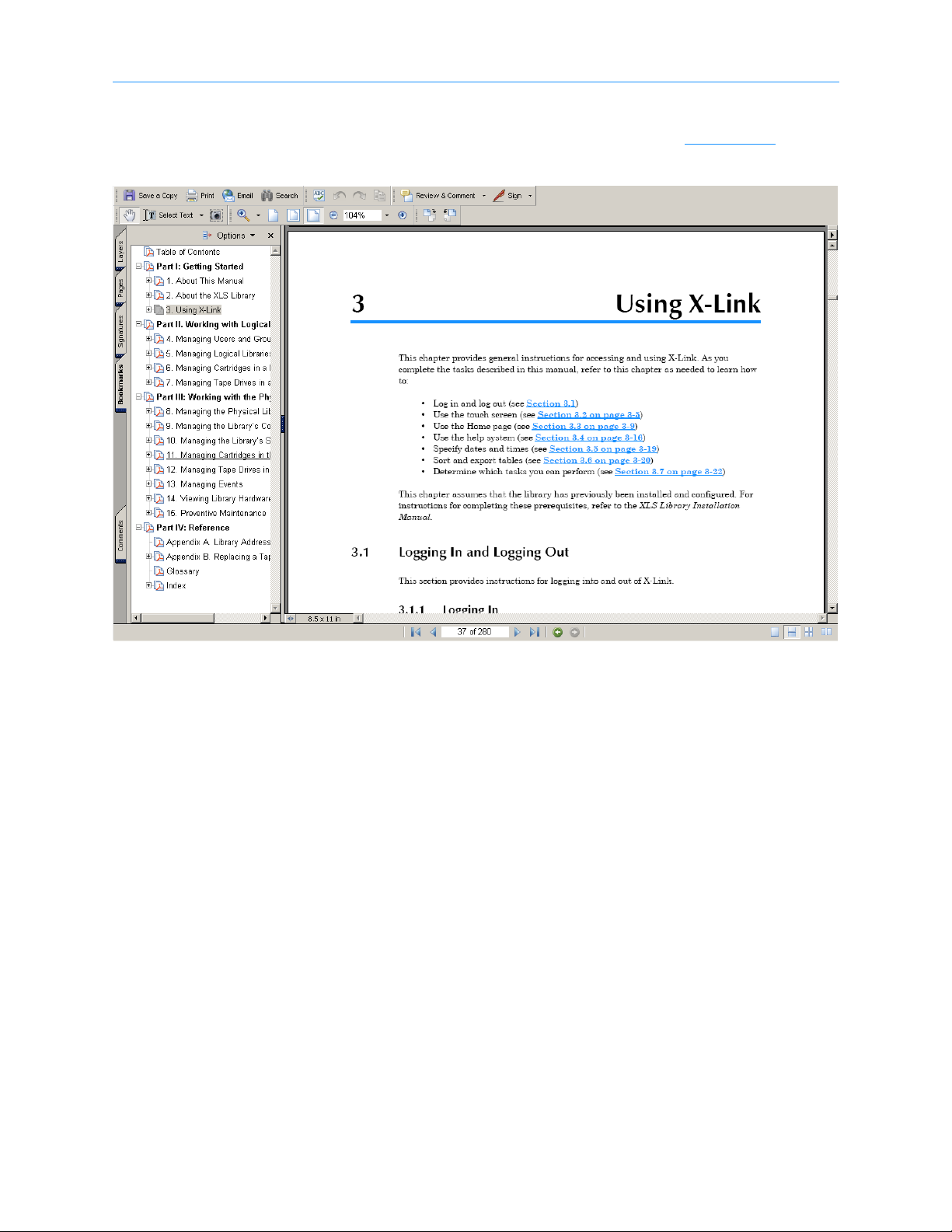
5. Select the manual you are interested in. Assuming that Adobe Acrobat or Acrobat
Reader is installed on your system, the PDF file opens. See Figure 1-19
.
Figure 1-19 PDF file of example manual opened in browser window
1-22 501801 Rev. A
 Loading...