

Qualstar TLS-8000, TLS-6000, TLS-5000 Service Manual

The Tape Library ExpertsTM
TLS-5000
TLS-6000
TLS-8000
Technical
Service Manual
501090 Rev. F
Important Manual/Firmware Revision Information
This manual and the operating firmware for the TLS are revised periodically as the
product is improved. This manual was revised to correspond with the firmware version indicated below. Do not use this manual with different part numbers or prior versions of the firmware. Check with Qualstar Technical Support about use of this manual with newer firmware.
Manual Corresponding Firmware
TLS-5000 / TLS-6000 / TLS-8000
Technical Service Manual
501090 Rev. F, 31 March 2006
Copyright Notice
TLS Executive Firmware 700105
Version 2.24
Copyright© 2006 by Qualstar Corporation — All Rights Reserved
Information contained in this document is copyrighted by Qualstar Corporation. It is
intended for use by Qualstar’s customers and prospective customers to evaluate, integrate, operate and maintain Qualstar products. Customers and prospective customers
may reproduce this document as needed for these uses. Reproduction in whole or in
part for any other use or by any other party is prohibited without prior written permission from Qualstar Corporation.
Every effort has been made to keep the information contained in this document current and accurate as of the date of publication or revision. However, no guarantee is
given or implied that the document is error-free or that it is accurate with regard to
any specification. Qualstar reserves the right to modify product designs and specifications without notice.
Qualstar and the Qualstar logo are registered trademarks of Qualstar Corporation.
Other trademarks are the property of their respective owners.
501090 Rev. F iii
Notices
Qualstar products are covered by one or more of the following patents:
6,163,139 and 6,560,061. Other patents pending.
Qualstar equipment is manufactured from new parts, or new and used parts. In some
cases, Qualstar equipment may not be new and may have been previously installed.
Regardless, Qualstar’s warranty terms apply unless the equipment is specifically
identified by Qualstar as “used” or “refurbished”.
This equipment has been tested and found to comply with the limits for a Class A
digital device, pursuant to Part 15 of the FCC Rules. These limits are designed to provide reasonable protection against harmful interference when the equipment is operated in a commercial environment. This equipment generates, uses, and can radiate
radio frequency energy and, if not installed and used in accordance with the instruction manual, may cause harmful interference to radio communications. Operation of
this equipment in a residential area is likely to cause harmful interference in which
case the user will be required to correct the interference at his own expense. Shielded
cables are required for this device to comply with FCC Rules. Use shielded cables
when connecting this device to others.
European Union Directive 89/336/EEC and Standard EN55022
(Electromagnetic Compatibility)
Warning
This is a Class A product. In a domestic environment this product may cause radio
interference in which case the user may be required to take adequate measures.
European Directive on Waste Electrical and Electronic Equipment (WEEE)
Qualstar encourages its customers to use current recycling practices in order to reduce the burden that waste electronic products place on the environment.
If you are retiring a fully functional tape library, you are encouraged to transfer the
functional unit to a new user, thereby extending the useful life of the tape library. The
manufacture of all products requires the consumption of energy. By extending the life
of the tape library, energy is conserved.
In accordance with environmental directives that are being implemented in many
countries (refer to the European Directive on Waste Electrical and Electronic Equipment - WEEE) Qualstar provides customers with “End of Life Instructions” that iden-
iv 501090 Rev. F

tify the process for recycling the materials and components that make up a Qualstar
tape library.
End of Life Instructions
Tools required
• P1 and P2 Phillips head screwdrivers
• T20 Torx head screwdriver
• Hex head (Allen) wrench/driver set
• 1/4-inch hex nut driver
Disassembly procedure
1. Remove door.
2. Remove top panel.
3. Remove side external panels.
4. Remove internal subassemblies.
Items recyclable using conventional methods
• Aluminum: Door, exterior panels, frame, robotics
Stainless steel: Robot guides
•
Steel: Some frames, fasteners
•
Plastic: Window, cartridge magazines, tape cassettes
•
Copper: Internal wiring, motors, SCSI cables
•
Paper: Manuals
•
Items requiring special disposal due to lead-based solder
• Printed Circuit Boards: Controller, miscellaneous small printed circuit
boards
Items that may have salvage or resale value
• Tape drives
• EMI line power filter
Reduction of Hazardous Substances (RoHS)
Qualstar is committed to the implementation of RoHS (Restriction of the use of certain hazardous substances in electrical and electronic equipment) in accordance with
501090 Rev. F v

the European Directive. The effectivity date for compliance is July 1, 2006, at which
time Qualstar will certify that its Tape Library products are compliant with the RoHS
standard. With the exception of Lead Based Solder, Qualstar will certify that its
products are free of all other substances listed in the Directive.
Qualstar Tape Libraries fall under the category of “Information Technology Storage
Array Systems” for which the RoHS Directive provides for a lead solder exemption until the year 2010. Insofar as lead free solders are new to the electronics industry and
no quality or reliability data is available, Qualstar will invoke the lead based solder
exemption until such time as industry data verifies that lead free solders are capable
of meeting or exceeding the documented reliability and quality standards achieved
with lead based solders.
Until such time as Qualstar replaces lead based solder with lead free solder, effected
subassemblies must be disposed of appropriately.
Technical Support Information
The best source for service-related information is your system reseller. Alternately,
the Qualstar Technical Support Department can be reached Monday through Friday,
between the hours of 7:30 A.M. and 4:30 P.M. Pacific Time, at:
Qualstar Corporation
3990-B Heritage Oak Court
Simi Valley, CA 93063
Attn: Technical Support
Fax: (805) 583-7749
Phone: (877) 444-1744
Monday – Friday 7:30 a.m. to 4:30 p.m. PST
After hours support: (805) 526-7480 or (805) 583-7748
E-Mail support@qualstar.com
E-Mail: sales@qualstar.com
Web: www.qualstar.com
vi 501090 Rev. F

Table of Contents
1. Introduction................................................................................................................... 1-1
1.1 Who Should Read This Manual................................................................................... 1-1
1.2 Important Safety Information ..................................................................................... 1-2
1.3 Lithium Battery............................................................................................................ 1-3
2. Description and Theory of Operation ..................................................................... 2-1
2.1 Model Identification ..................................................................................................... 2-1
2.2 General Description ..................................................................................................... 2-3
2.2.1 Motion Systems ........................................................................................................ 2-3
2.2.2 Sensors...................................................................................................................... 2-4
2.2.3 Handler Solenoid...................................................................................................... 2-6
2.2.4 Barcode Reader ........................................................................................................ 2-6
2.2.5 Barcode Labels ......................................................................................................... 2-6
2.2.6 Barcode Label Usage ............................................................................................... 2-7
2.3 Component Identification ............................................................................................ 2-7
2.3.1 Handler................................................................................................................... 2-14
2.3.2 I/O Port Assembly .................................................................................................. 2-14
2.3.3 Field-Replaceable Units (FRUs) ........................................................................... 2-15
3. The Menu System ......................................................................................................... 3-1
3.1 Using the Menu Control Keys ..................................................................................... 3-1
3.1.1 The MENU Control Key .......................................................................................... 3-1
3.1.2 The V (UP) and W (DOWN) Control Keys ............................................................. 3-1
3.1.3 The ENTER Control Key......................................................................................... 3-2
3.1.4 The EXIT Control Key ............................................................................................. 3-3
3.1.5 The @ (Daisy) Key and I/O Port Operation ........................................................... 3-3
3.2 The Top Menu............................................................................................................... 3-5
3.3 Menu Elements............................................................................................................. 3-6
3.3.1 Menu Items............................................................................................................... 3-6
3.3.2 Values ....................................................................................................................... 3-6
3.3.3 Location Designators ............................................................................................... 3-7
3.3.4 Editing Values.......................................................................................................... 3-8
3.4 The Menu Hierarchy .................................................................................................. 3-11
3.5 Displaying the TLS Firmware Revision ................................................................... 3-11
3.6 Alerts ........................................................................................................................... 3-12
3.7 Dynamic Menus and Menu Items ............................................................................. 3-12
4. Maintenance Menu....................................................................................................... 4-1
4.1 Maintenance Menu....................................................................................................... 4-2
4.2 Maintenance\Display Log Menu ................................................................................ 4-3
501090 Rev. F vii

4.2.1 Maintenance\Display Log\CLEAR Command ..................................................... 4-4
4.2.2 Maintenance\Display Log\LOCK Command........................................................ 4-4
4.2.3 Maintenance\Display Log\UNLOCK Command.................................................. 4-4
4.3 Maintenance\Display Log\Display\Entry Menu ..................................................... 4-5
4.4 Maintenance\Display\Prevents Status Screen......................................................... 4-6
4.5 Maintenance\Display Revision Status Screen .......................................................... 4-7
4.6 Maintenance\Display Stats. Status Screen ............................................................... 4-7
4.7 Maintenance\Display Stats. (Left or Right) Status Screen ...................................... 4-9
4.8 Maintenance\Display Voltage Status Screen ............................................................ 4-9
4.9 Maintenance\Test Inventory Status Screen ............................................................ 4-10
4.10 Maintenance\Test Keyboard Status Screen......................................................... 4-10
4.11 Maintenance\Test LC Display Status Screen ...................................................... 4-11
5. The Private Menu ......................................................................................................... 5-1
5.1 Introduction .................................................................................................................. 5-2
5.2 Defeating Security Locks ............................................................................................. 5-3
5.2.1 Door Lock.................................................................................................................. 5-3
5.2.2 Master Lock.............................................................................................................. 5-3
5.2.3 Disabling the Master Security Lock ....................................................................... 5-3
5.3 Enabling the Private Menu ......................................................................................... 5-4
5.3.1 Access........................................................................................................................ 5-4
5.3.2 Setting a Password .................................................................................................. 5-5
5.3.3 Clearing the Password............................................................................................. 5-7
5.4 The Private Menu......................................................................................................... 5-8
5.4.1 Private\CALIBRATE Command ............................................................................ 5-8
5.4.2 Private\CLEAR ACCESS Command ..................................................................... 5-9
5.4.3 RESET SCSI BUS Command.................................................................................. 5-9
5.4.4 The Private\Blower Menu .................................................................................... 5-10
5.4.5 The Private\Calibration Data Status Screens .................................................... 5-11
5.4.6 The Private\Carousel Menu ................................................................................. 5-12
5.4.7 The Private\Configuration Menu......................................................................... 5-15
5.4.8 The Private\Configuration\Defaults Menu ........................................................ 5-15
5.4.9 The Private\Configuration\SCSI Menu.............................................................. 5-16
5.4.10 The Private\Display A/D Status Screen .............................................................. 5-17
5.4.11 The Private\Display Locations Menu .................................................................. 5-18
5.4.12 The Private\Display Positions Status Screen ..................................................... 5-20
5.4.13 The Private\Display Sensors Status Screen ....................................................... 5-21
5.4.14 The Private\DriveBay Menu ................................................................................ 5-22
5.4.15 The Private\Executive Menu................................................................................ 5-27
6. Troubleshooting............................................................................................................ 6-1
6.1 Power Up and Initialization Failures ......................................................................... 6-3
viii 501090 Rev. F

6.2 Operation Failures ..................................................................................................... 6-10
6.3 Calibration Failures ................................................................................................... 6-14
7. Field–Replaceable Units (FRUs)............................................................................... 7-1
7.1 Introduction .................................................................................................................. 7-1
7.2 Field-Replaceable Units (FRUs).................................................................................. 7-2
7.3 Required Tools and Materials ..................................................................................... 7-3
7.4 Top and Side Panels ..................................................................................................... 7-4
7.4.1 Top Panel Removal .................................................................................................. 7-5
7.4.2 Top Panel Replacement ........................................................................................... 7-5
7.4.3 Side Panel Removal (Left or Right) ........................................................................ 7-6
7.4.4 Side Panel Replacement (Left or Right) ................................................................. 7-7
7.5 Carriage Assemblies..................................................................................................... 7-8
7.5.1 Carriage Assembly Removal ................................................................................. 7-10
7.5.2 Carriage Assembly Replacement .......................................................................... 7-15
7.5.3 Lubricating the Vertical (Y) Axis Leadscrew ....................................................... 7-19
7.6 Carriage PCBA ........................................................................................................... 7-20
7.6.1 Carriage PCBA Removal ....................................................................................... 7-20
7.6.2 Carriage PCBA Replacement................................................................................ 7-21
7.7 Barcode Reader........................................................................................................... 7-22
7.7.1 Barcode Reader Removal....................................................................................... 7-23
7.7.2 Barcode Reader Replacement ............................................................................... 7-23
7.8 Air Filter and Fan Assembly ..................................................................................... 7-24
7.8.1 Air Filter Removal/Replacement .......................................................................... 7-24
7.8.2 Fan Assembly Removal for 6110, 62xx, 8111 and 82xx Models ......................... 7-26
7.8.3 Fan Assembly Replacement for 6110, 62xx, 8111 and 82xx Models .................. 7-27
7.8.4 Fan Assembly Removal for 54xx, 64xx and 84xx Models.................................... 7-29
7.8.5 Fan Assembly Replacement for 54xx, 64xx and 84xx Models ............................ 7-31
7.9 Air Filters and Blower Assembly .............................................................................. 7-34
7.9.1 Air Filter Removal/Replacement .......................................................................... 7-34
7.9.2 Blower Assembly Removal .................................................................................... 7-36
7.9.3 Blower Assembly Replacement ............................................................................. 7-37
7.10 I/O Port Assembly ................................................................................................... 7-38
7.10.1 I/O Port Assembly Removal................................................................................... 7-40
7.10.2 I/O Port Assembly Replacement ........................................................................... 7-40
7.11 I/O Port PCBA ......................................................................................................... 7-41
7.11.1 I/O Port PCBA Removal ........................................................................................ 7-41
7.11.2 I/O Port PCBA Replacement ................................................................................. 7-42
7.12 Switch Bracket Assembly (Front Panel) ............................................................... 7-43
7.12.1 Switch Bracket Assembly Removal ...................................................................... 7-43
7.12.2 Switch Bracket Assembly Replacement ............................................................... 7-44
501090 Rev. F ix

7.13 Handler Power Supplies......................................................................................... 7-46
7.13.1 Single Bay Handler Power Supply Removal - 6110 and 8111 Models ............... 7-47
7.13.2 Single Bay Handler Power Supply Replacement - 6110 and 8111 Models........ 7-48
7.13.3 Single Bay Handler Power Supply Removal - 54xx, 62xx, 64xx, 82xx and
84xx Models............................................................................................................ 7-48
7.13.4 Single Bay Handler Power Supply Replacement - 54xx, 62xx, 64xx, 82xx
and 84xx Models..................................................................................................... 7-50
7.13.5 Dual Bay Handler Power Supply Removal .......................................................... 7-51
7.13.6 Dual Bay Handler Power Supply Replacement ................................................... 7-54
7.14 Blower Power Supply.............................................................................................. 7-55
7.14.1 Blower Power Supply Removal ............................................................................. 7-55
7.14.2 Blower Power Supply Replacement...................................................................... 7-56
7.15 Tape Drive Power Supply....................................................................................... 7-57
7.15.1 Tape Drive Power Supply Removal ...................................................................... 7-58
7.15.2 Tape Drive Power Supply Replacement ............................................................... 7-60
7.16 Executive PCBA...................................................................................................... 7-60
7.16.1 Executive PCBA Removal ..................................................................................... 7-61
7.16.2 Executive PCBA Replacement .............................................................................. 7-63
7.16.3 Reconfiguring the TLS........................................................................................... 7-66
7.16.4 Recalibrating the TLS............................................................................................ 7-69
7.17 Drive Bay PCBA...................................................................................................... 7-69
7.17.1 Drive Bay PCBA Removal 6110 and 8111 Models .............................................. 7-70
7.17.2 Drive Bay PCBA Replacement 6110 and 8111 Models ....................................... 7-71
7.17.3 Drive Bay PCBA Removal 62xx and 82xx Models............................................... 7-72
7.17.4 Drive Bay PCBA Replacement 62xx and 82xx Models........................................ 7-74
7.17.5 Drive Bay PCBA Removal 54xx, 64xx and 84xx Models..................................... 7-76
7.17.6 Drive Bay PCBA Replacement 54xx, 64xx and 84xx Models.............................. 7-78
7.17.7 Drive Bay PCBA Replacement for58xxx, 68xxx and 88xxx Models ................... 7-80
7.18 Carousel PCBA........................................................................................................ 7-87
7.18.1 Carousel PCBA Removal....................................................................................... 7-87
7.18.2 Carousel PCBA Replacement................................................................................ 7-89
7.19 Carousel Motor........................................................................................................ 7-90
7.19.1 Single Bay Carousel Motor Removal (54xx, 62xx, 64xx, 82xx and 84xx
Libraries) ................................................................................................................ 7-90
7.19.2 Single Bay Carousel Motor Replacement (54xx, 62xx, 64xx, 82xx and 84xx
Libraries) ................................................................................................................ 7-93
7.19.3 Dual Bay Carousel Motor Removal (58xxx, 68xxx and 88xxx Libraries) .......... 7-94
7.19.4 Dual Bay Carousel Motor Replacement (58xxx, 68xxx and 88xxx Libraries) ... 7-98
7.20 SCSI High Voltage Differential Adapter PCBA ................................................... 7-99
7.20.1 SCSI High Voltage Differential Adapter PCBA Removal................................. 7-100
7.20.2 SCSI High Voltage Differential Adapter PCBA Replacement.......................... 7-100
x 501090 Rev. F

7.21 Q-Link.................................................................................................................... 7-102
7.21.1 Q-Link Removal ................................................................................................... 7-102
7.21.2 Q-Link Replacement ............................................................................................ 7-103
7.22 Shuttle Assembly .................................................................................................. 7-104
7.22.1 Shuttle Assembly Removal.................................................................................. 7-104
7.22.2 Shuttle Assembly Replacement .......................................................................... 7-106
7.23 Shuttle PCBAs ...................................................................................................... 7-107
7.23.1 Shuttle PCBA Removal ....................................................................................... 7-107
7.23.2 Shuttle PCBA Replacement ................................................................................ 7-108
7.24 Y-Clear Detector PCBA ........................................................................................ 7-109
7.24.1 Y-Clear Detector PCBA Removal........................................................................ 7-109
7.24.2 Y-Clear Detector PCBA Replacement ................................................................ 7-110
7.25 After-maintenance Test Procedures .................................................................... 7-111
8. Firmware Updating ..................................................................................................... 8-1
8.1 Firmware Replacement................................................................................................ 8-1
8.2 Determining the Installed Hardware and Required Firmware ................................ 8-1
8.2.1 Firmware Update via the SCSI or Fibre Channel Interface................................. 8-3
8.3 Firmware Update via Q-Link ...................................................................................... 8-5
8.4 Firmware Update via Q-Conn ..................................................................................... 8-7
8.4.1 RS-232 Cable Wiring ............................................................................................... 8-8
8.4.2 RS-232 Serial Communications Parameters.......................................................... 8-8
8.4.3 User Terminal Software Setup Example ............................................................... 8-8
8.4.4 VT100 Terminal Emulation .................................................................................. 8-10
8.4.5 Remote Library Command Mode .......................................................................... 8-11
8.4.6 Xmodem Firmware Download <xdl> .................................................................... 8-11
8.4.7 Procedure for Replacing the Flash-Memory IC on Executive II, III or IV
Boards ..................................................................................................................... 8-13
9. TLS Expansions ............................................................................................................ 9-1
9.1 Introduction .................................................................................................................. 9-1
9.2 Model Expansions......................................................................................................... 9-2
9.2.1 Installing a Model Expansion Kit........................................................................... 9-2
9.2.2 Entering the Update Password............................................................................. 9-10
9.2.3 Reconfiguring the Model Number......................................................................... 9-11
9.2.4 Recalibrating the Unit........................................................................................... 9-12
9.2.5 Clearing the Password........................................................................................... 9-12
9.3 Barcode Reader........................................................................................................... 9-12
9.3.1 Required Parts and Tools ...................................................................................... 9-12
9.3.2 Barcode Reader Installation.................................................................................. 9-13
501090 Rev. F xi
1. Introduction
1.1 Who Should Read This Manual
This Technical Service Manual is for Tape Library System (TLS) service personnel. It
describes the Maintenance Menu, the Private Menu and instructions for removing
and replacing Field Replacement Units (FRU's). It also contains troubleshooting procedures and after–maintenance testing procedures.
The following topics are covered in the TLS-5000/6000/8000 Installation and Operation Manual (Qualstar document number 501450):
Unpacking Instructions
•
•
Control Panel
•
Menu System
•
System Configuration
•
System Operation
•
Preventative Maintenance
•
Repacking Instructions
For information about the SCSI interface, or other information outside the scope of
this manual, please refer to the appropriate documents listed below.
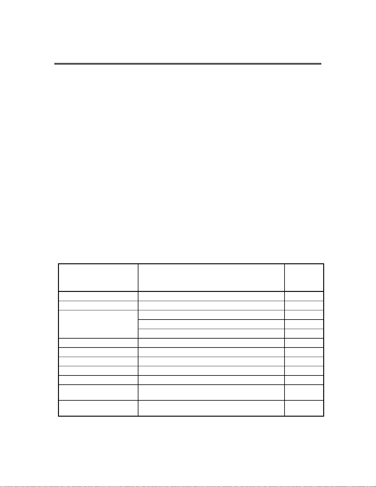
Subject
Document
Qualstar
Document
Number
SCSI Command Information TLS-5000/6000/8000 SCSI-2 Interface Manual 501205
Installation and Operation TLS-5000/6000/8000 Installation and Operation Manual 501450
Specifications
Fibre Channel Option Fibre Channel Option Installation and Operation Manual 501440
Supported Tape Drives Product Information Note PIN-014
Approved Data Cartridges Product Information Note PIN-038
Barcode Label Specifications Product Information Note PIN-040
SCSI-2 ANSI X3.131-1994 N/A
SCSI SPI-2 Specification ANSI X3.302-1998
SCSI-3 ANSI X3.253:199X
TLS-5000 Product Specification 501561
TLS-6000 Product Specification 501080
TLS-8000 Product Specification 501498
SCSI Parallel Interface-2 (SPI-2)
and Amendment AM1 to X3.253.1995
N/A
N/A
Table 1-1 Applicable Documents
501090 Rev. F Introduction 1-1

Although Qualstar has made every effort to insure the accuracy of the information
contained in this manual, no guarantee is expressed or implied that the manual is
error-free. Qualstar reserves the right to make changes at any time without prior notification.
The Qualstar Tape Libraries are sophisticated, state-of-the-art computer peripherals.
They should only be serviced by a competent service technician who is experienced
with the operation and maintenance of tape libraries, and only after reading and understanding this manual and the TLS-5000/6000/8000 Installation and Operation
Manual.
1.2 Important Safety Information
All of the operating instructions and maintenance procedures in Qualstar manuals
must be followed to prevent personal injury or damage to the equipment. In the interests of safety, there are two kinds of warnings used in Qualstar documents, as shown
below.
DANGER
PERSONAL INJURY MAY RESULT IF YOU DO NOT FULLY COMPLY WITH THE
HANDLING, OPERATING, OR SERVICE INSTRUCTIONS FOUND IN A DANGER
PARAGRAPH.
GEFAHR
UNSACHGEMAESSE BENUTZUNG, BEDLENUNG ODER RAPARATUR
AUFGRUND VON NICHTBEGEFAHR DER SICHERHEITSANWEISUNG KANN ZU
VERIET-ZUNGEN FUEHREN.
CAUTION
EQUIPMENT DAMAGE OR LOSS OF DATA may result if you do not fully comply
with the handling, operating, or service instructions found in a CAUTION paragraph.
In addition, useful information and tips may be found throughout the document in the
following formats:
NOTE
SPECIAL ATTENTION to explanatory statements found in a NOTE paragraph will help you avoid
mistakes and/or save time.
1-2 Introduction 501090 Rev. F

A NOTICE box contains additional important information.
1.3 Lithium Battery
Please observe the following information when repairing the unit.
U9, A DALLAS SEMICONDUCTOR CORPORATION DS1225AB OR A SGSTHOMPSON MICROELECTRONICS M48258X IC ON THE EXECUTIVE PCBA
CONTAINS AN INTEGRAL LITHIUM BATTERY. AN EXPLOSION DANGER EXISTS
IF THE IC IS INCORRECTLY REPLACED. REPLACE THE IC ONLY WITH THE SAME
PART NUMBER, OR AN EQUIVALENT DESIGNATED BY THE MANUFACTURER.
DISPOSE OF THE USED IC ACCORDING TO THE MANUFACTURER'S
INSTRUCTIONS.
NOTICE
DANGER
GEFAHR
DER U9, EIN DALLAS SEMICONDUCTOR CORPORATION DS1225AB ODER EIN
A SGS-THOMPSON MICROELECTRONICS M48258X IC AUF DEM EXECUTIVE
BOARD ENTHAELT EINE INTEGRIERTE LITHIUM BATTERIE. WENN DIESE
UNSACHGEMAESS AUSGETAUSCHT WIRD, BESTEHT EXPLOSIONS GEFAHR.
DER IC DARF NUR DURCH EINEN ARTIKEL MIT DER SELBEN ARTIKELNUMMER,
BZW, MIT EINEM VERGLEICHBAREN ARTIKEL LAUT HERSTELLER ANGABE
ERSETZT WERDEN. DIE ENTSORGUNG DES ALTEN IC’S DARF NUR GEMAESS
HERSTELLERANGABEN ERFOLGEN.
501090 Rev. F Introduction 1-3
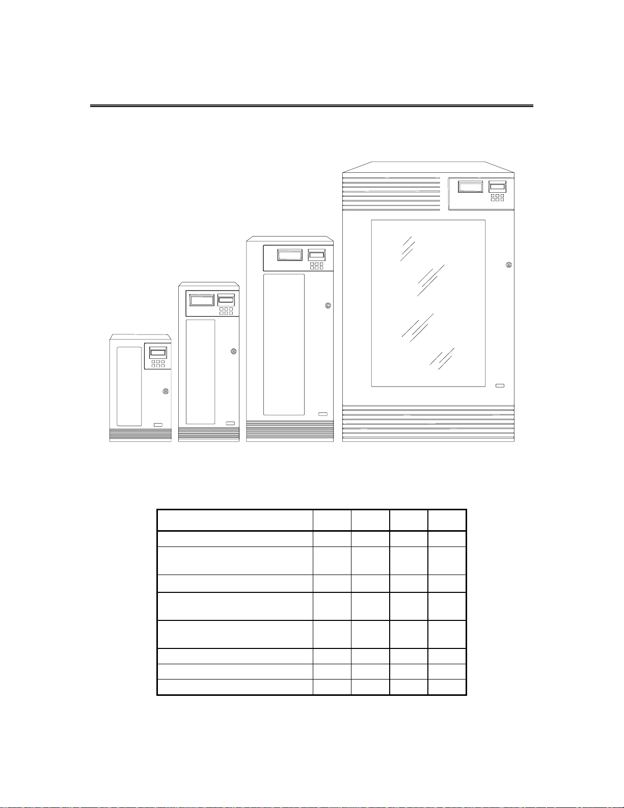
2. Description and Theory of Operation
2.1 Model Identification
6110
8111
Figure 2-1 TLS-5000/6000/8000 Models
6210, 6220
8211, 8222
5433, 5466
6430, 6460
8433, 8466
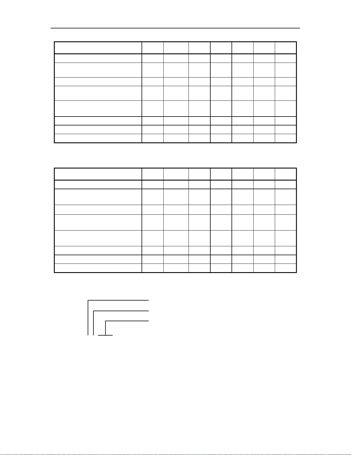
TLS-5000 Feature/Model 5433 5466 58132 58264
Maximum number of tape drives 4 4 8 8
Media capacity in cartridges
(11 cartridges per magazine)
Barcode Reader(s)
I/O Port for automated cartridge
insertion/removal
Carousel(s)
(rotary positioning of magazines)
Number of Cartridge Handlers 1 1 2 2
Fibre Channel Option Opt. Opt. Opt. Opt.
Q-Link Remote Manager Opt. Opt. Opt. Opt.
Table 2-1 SAIT based TLS-5000 Features
58132, 58264
68120, 68240
88132, 88264
33 66 132 264
Std. Std. Std. Std.
Std. Std. Std. Std.
1 1 2 2
501090 Rev. F Description and Theory of Operation 2-1
r
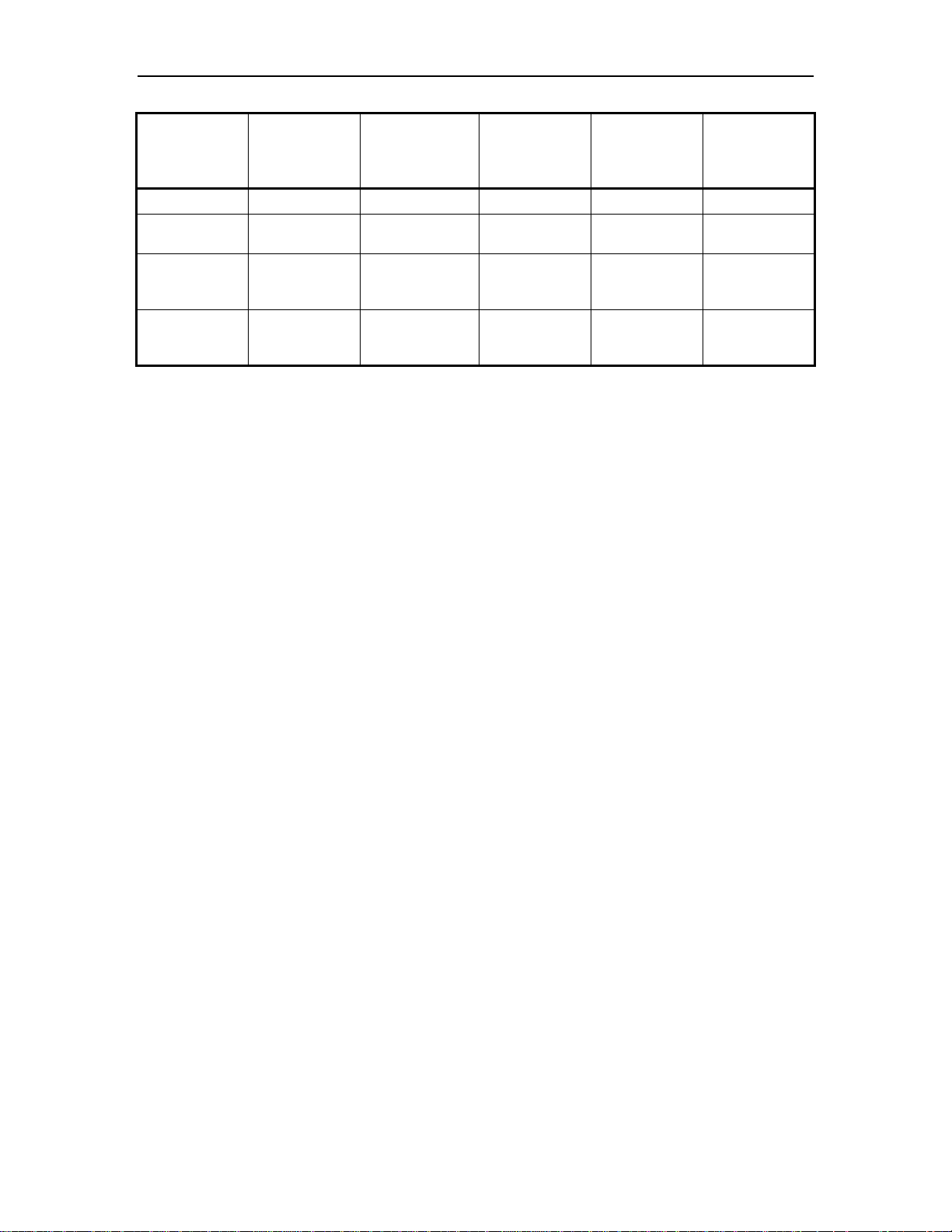
TLS-6000 Feature/Model 6110 6210 6220 6430 6460 68120 68240
Maximum number of tape drives 1 2 2 4 4 8 8
Media capacity in cartridges
(10 cartridges per magazine)
Barcode Reader(s) Opt. Opt. Opt. Std. Std. Std. Std.
I/O Port for automated cartridge
insertion/removal
10 10 20 30 60 120 240
N/A Opt. Opt. Std. Std. Std. Std.
Carousel(s)
(rotary positioning of magazines)
Number of Cartridge Handlers 1 1 1 1 1 2 2
Fibre Channel Option N/A Opt. Opt. Opt. Opt. Opt. Opt.
Q-Link Remote Manager Opt. Opt. Opt. Opt. Opt. Opt. Opt.
N/A Opt. 1 1 1 2 2
Table 2-2 SDLT based TLS-6000 Features
TLS-8000 Feature/Model 8111 8211 8222 8433 8466 88132 88264
Maximum number of tape drives 1 2 2 4 4 8 8
Media capacity in cartridges
(11 cartridges per magazine)
Barcode Reader(s)
I/O Port for automated cartridge
insertion/removal
Carousel(s)
(rotary positioning of magazines)
Number of Cartridge Handlers 1 1 1 1 1 2 2
Fibre Channel Option N/A Opt. Opt. Opt. Opt. Opt. Opt.
Q-Link Remote Manager Opt. Opt. Opt. Opt. Opt. Opt. Opt.
11 11 22 33 66 132 264
Opt. Opt. Opt. Std. Std. Std. Std.
N/A Opt. Opt. Std. Std. Std. Std.
N/A Opt. 1 1 1 2 2
Table 2-3 LTO based TLS-8000 Features
Series Identifie
Maximum Number of Drives
Maximum Number of Cartridges in Maga zines
TLS-00000
Figure 2-2 Model Number Identification Scheme
This manual applies to all models. The installation and operation of the various models is virtually identical. Models 58xxx, 68xxx and 88xxx are referred to as dual bay
libraries because of their dual Drive Bays. All other models are single bay libraries.
Differences among the models are noted where required.
2-2 Description and Theory of Operation 501090 Rev. F
MODEL
6110, 8111
6210, 6220
8211, 8222
5433, 5466
6430, 6460
8433, 8466
58132, 58264
68120, 68240
88132, 88264
{ Stabilizer feet add 5.0 inches (12.7 cm) to the base width of the 54xx, 62xx, 64xx, 82xx and 84xx se-
ries.
| Shipping weights include the TLS, data cartridge magazines and accessories.
} Weight includes accessory box (shipped separately).
~ Empty weights exclude tape drives, magazines and data cartridges.
HEIGHT
(in./cm)
22.9 / 58.2 13.1 / 33.3 24.9 / 63.2 58 / 26.3 90 / 40.8
34.7 / 88.1
44.5 / 113.0
61.9 / 157.3 37.25 / 94.62 30.5 / 77.5 359 / 163
WIDTH
(in./cm)
13.1 / 33.3
18.75 / 47.6
DEPTH
(in./cm)
{
{
24.9 / 63.2 89 / 40.3
30.5 / 77.5 153 / 163
EMPTY
WEIGHT
(lb./kg)
~
SHIPPING
WEIGHT
125 / 56.7
235 / 107
602 / 273
Table 2-4 TLS Dimensions (fully loaded units)
2.2 General Description
d
(lb./kg)
}
}
}
The three family members of Qualstar’s ½-inch TLS series of tape libraries are:
• TLS-5000 series utilizing SAIT (SuperAIT) tape technology
• TLS-6000 series utilizing SDLT (SuperDLT) tape technology
• TLS-8000 series utilizing LTO (all generations) tape technology
Each TLS-5000/6000/8000 cabinet contains a high-performance robotics system for
handling data cartridges, one or two drive bays to accommodate the cartridge tape
drives, removable cartridge magazines, power supplies and printed circuit board assemblies (PCBAs) that contain the TLS electronics. An I/O port for inserting and removing cartridges under secured host system control is supported in every model, except for the 6110 and 8111 models. All units operate on any internationally available
AC power source, with the TLS power cable and SCSI interface cables being the only
required connections. The entire cabinet is pressurized and cooled by filtered air to
ensure an optimum operating environment.
These tape libraries are not intended for use in mobile applications. They were designed for use in an office environment.
2.2.1 Motion Systems
The TLS contains up to five independent motion systems.
• Carriages move up and down vertically along the Vertical (Y) Axis and are
driven by brushless DC motors, which turn a nut around a fixed, precision
leadscrew.
501090 Rev. F Description and Theory of Operation 2-3

• Handler assemblies extend and retract along the Insertion (Z) Axis and
are driven by brushless DC motors that turn precision leadscrews.
• The I/O port slot extends to receive or deliver a cartridge and then retracts. The I/O port slot's leadscrew is driven by a DC stepper motor.
• A large gear at the bottom of each Carousel Assembly is turned by a pinion
gear on a DC stepper motor.
• On dual bay libraries, models 58xxx, 68xxx and 88xxx, the Shuttle travels
along the Horizontal (X) Axis to allow for the transferring on single cartridges between the left and right sides. It is driven by a brushless DC motor that turns a leadscrew.
The drive circuitry for all motion systems is located on the Executive Printed Circuit
Board Assemblies (PCBAs). Each of the brushless DC motors has three internal HallEffect sensors. The Hall-Effect sensors are used to commutate the motors and determine their relative positions. The brushless DC motors are driven by a three-phase
MOSFET bridge, using a 12 volt supply. Each stepper motor is driven by four discrete
MOSFET devices from the same 12 volt supply.
Each motion system has an opto-switch (infrared, opto-interrupter-type detector),
which is used to determine its reference position.
2.2.2 Sensors
TLS models have two types of infrared optical sensors: analog and digital. Each optical sensor has two parts: an emitter and a corresponding detector.
Analog Sensor Operation
Analog sensors are used over longer distances than the digital sensors, which have a
range of about only one inch.
All analog infrared optical sensors produce a DC voltage proportional to the strength
of the infrared signal at the sensor. This signal is measured by the Analog to Digital
(A/D) Converter on the Executive PCBAs.
Analog Sensors
• Y-Clear Sensors
These sensors are referred to in the Installation and Operation Manual as
the Inventory Sentry Beam. A sensor consists of an infrared emitter
mounted on the bottom pan and a detector mounted at the top of the library. The detector in single bay libraries library is mounted on the I/O
port PCBA. The detector on the right side of dual bay libraries is mounted
on the I/O port PCBA and the one on the left side is mounted on the YReceiver PCBA. The infrared beam is modulated at a high frequency. The
sensor circuitry is AC–coupled to eliminate its sensitivity to ambient light.
The Y-Clear sensor serves three purposes:
1. When the front door is closed, the Y–Clear sensor verifies that the vertical path
traveled by the handler is unobstructed and that it is therefore safe for the carriage
to move vertically.
2-4 Description and Theory of Operation 501090 Rev. F

2. When the front door is open, the Y–Clear sensor determines whether or not the
inventory has been violated by someone reaching inside the cabinet and removing or
inserting a cartridge. Just the presence of someone's hand between the Y–Clear sensor’s emitter and detector is sufficient to interrupt the sensor’s infrared beam and
trigger an audible alarm.
3. When inserting and removing cartridges, the Y–Clear sensor is used in conjunction with the Cartridge Presence sensor to check the position of a cartridge in the
Handler's Gripper Assembly.
• Cartridge Presence Sensors
These sensors, which are mounted on handlers, detect the presence of a
tape cartridge in any storage location, including a tape drive (cartridge
must be in ejected position). They utilize the same modulated circuit as
the Y–Clear sensors. The Cartridge Presence sensors also work in conjunction with the Y–Clear sensors to determine the position of a cartridge in a
Handler's Gripper Assembly.
Digital Sensor Operation
The processor on the Executive PCBAs read the digital signals produced by the digital
sensors’ detectors.
The carousel axis has a position sensor, which looks at a pattern encoded on the gear
guard. The other three axes of motion (I/O port, vertical and insertion) have home position sensors. These sensors are used for reference purposes during initialization and
operation.
Digital Sensors
• Door Sensor
This sensor detects the condition of the cabinet door: open or closed.
When a door-open condition is detected, the system stops all moving assemblies.
• Carousel Position Sensors
The pattern output to these sensors by a carousel is used to determine the
position of the carousel(s).
• Vertical Axis Home Sensors
These sensors use the tall pin(s) mounted in the bottom of the cabinet to
detect when each Carriage Assembly reaches its home position at the bottom of the cabinet.
• Insertion Axis Home Sensors
These sensors detect when a Carriage’s Handler Assembly (on the Insertion Axis) is in its home position: fully retracted.
• I/O Port Full Sensor
This sensor detects when a tape cartridge is fully inserted into the I/O port
slot. It consists of an infrared emitter on a small PCBA in the I/O port assembly and a sensor on the I/O port PCBA.
501090 Rev. F Description and Theory of Operation 2-5

• I/O Port Home Sensor
This sensor detects when the I/O port slot is in its home position: fully retracted.
• I/O Port Clear Sensor
This sensor detects the presence of a tape cartridge in the I/O port slot.
2.2.3 Handler Solenoid
A solenoid–operated Gripper Assembly is mounted on each Handler for grasping and
releasing cartridges. When current is applied to the solenoid's windings, the solenoid's
plunger extends, opening the Gripper. When the current is removed, a spring closes
the Gripper. The solenoid plunger's tip is covered with a wear-resistant nosepiece to
provide extended life.
2.2.4 Barcode Reader
A barcode reader for each carriage is standard on TLS-58xxx, 68xxx an 88xxx models.
For single bay libraries, a barcode reader is standard on models TLS-54xx, 64xx and
TLS-84xx, and optional on the others. They are intended for use in systems where
each cartridge is identified by a barcode label. Pre-printed barcode labels, which are
both human- and machine-readable, are available from a number of sources, including
Qualstar.
The barcode reader consists of a charge-coupled sensor (similar to those used in video
cameras) and associated electronics. They are mounted under the carriages. The barcode readers can scan all cartridges in the TLS (except those loaded inside LTO tape
drives), as well as cartridges introduced into the I/O port.
The changer automatically moves a cartridge in the I/O port slot, to a temporary location where
its barcode label can be scanned. The changer then returns the cartridge to its original location.
2.2.5 Barcode Labels
Pre-printed barcode labels, which are both human- and machine-readable, are available from a number of sources including Qualstar.
Barcode labels must conform to ANSI/AIM BCI-1995, Uniform Symbology Specification Code 39. Please refer to PIN-040 at www.qualstar.com (click on Support tab) for
more information.
By default, the TLS expects a modulus 43 check character at the end of each label.
The use of a check character helps assure that labels are read error-free. The TLS configuration must be changed before using barcode labels without a check character. All
of the labels within the TLS must match the check character configuration: either all
with or all without a check character.
NOTE
2-6 Description and Theory of Operation 501090 Rev. F

2.2.6 Barcode Label Usage
If the library contains a barcode reader (and barcode labels are affixed to the cartridges), when barcode information is read, it is stored as part of the inventory database in the library's non-volatile RAM, and is available to the host computer upon request. When the changer moves a cartridge, the inventory database is updated to reflect the change.
If the changer’s inventory becomes invalid (e.g. if the Inventory Sentry Beam is violated), the changer rescans the inventory. The updated barcode label and cartridge
position data is then stored in the inventory database. Example: After an alert that
invalidates the inventory (e.g., when a cartridge is moved by hand) is cleared, the
changer rescans the inventory. Any existing barcode labels are read and the new inventory data is stored in the inventory database.
By default, the library expects a modulus 43 check character. The user must change
the changers’ configuration option before using barcode labels without a check character. All of the labels within the TLS must be of the same check character definition:
either all with or all without.
The following steps will allow the changers’ configuration option to be set to not expect a check character.
1. Press the MENU key to display the
2. Press the ENTER key once to enter the
3. Press the ENTER key once to enter the
4. Press the ENTER key once to enter the
\Configuration\Advanced\Changer menu.
5. Use the W (DOWN) key to move the pointer to
6. Press the ENTER key once to begin editing the
7. Press the V (UP) or W (DOWN) key to change the
YES to NO.
from
8. Press the MENU key to return to the
2.3 Component Identification
Most of the major components are common to all models. The number of tape drives
varies between models (from one to eight), depending upon the size of the TLS and the
number of drives installed.
Top Menu.
\Configuration menu.
\Configuration\Advanced menu.
LabelCheckChar.
LabelCheckChar value.
LabelCheckChar value
Top Menu.
Figure 2-3 through Figure 2-8 show the location of the major components in TLS5000/6000/8000 models.
501090 Rev. F Description and Theory of Operation 2-7
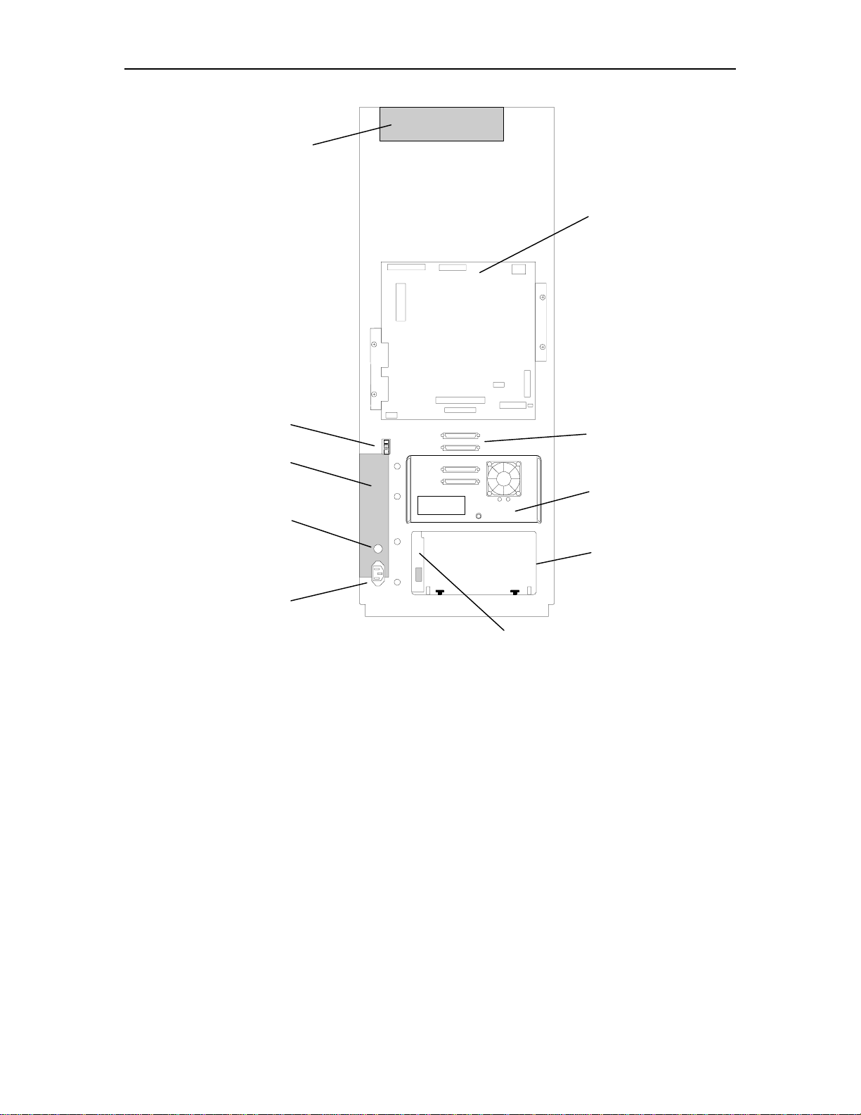
y
r
y
Handler Power Suppl
Executive PCBA
Power Switch
Tape Drive
Power Suppl
Fuse
AC Powe
Receptacle
Figure 2-3 Single Bay TLS Rear View
SCSI Connectors
Tape Drive
Tape Drive Slot
Drive Bay PCBA
2-8 Description and Theory of Operation 501090 Rev. F
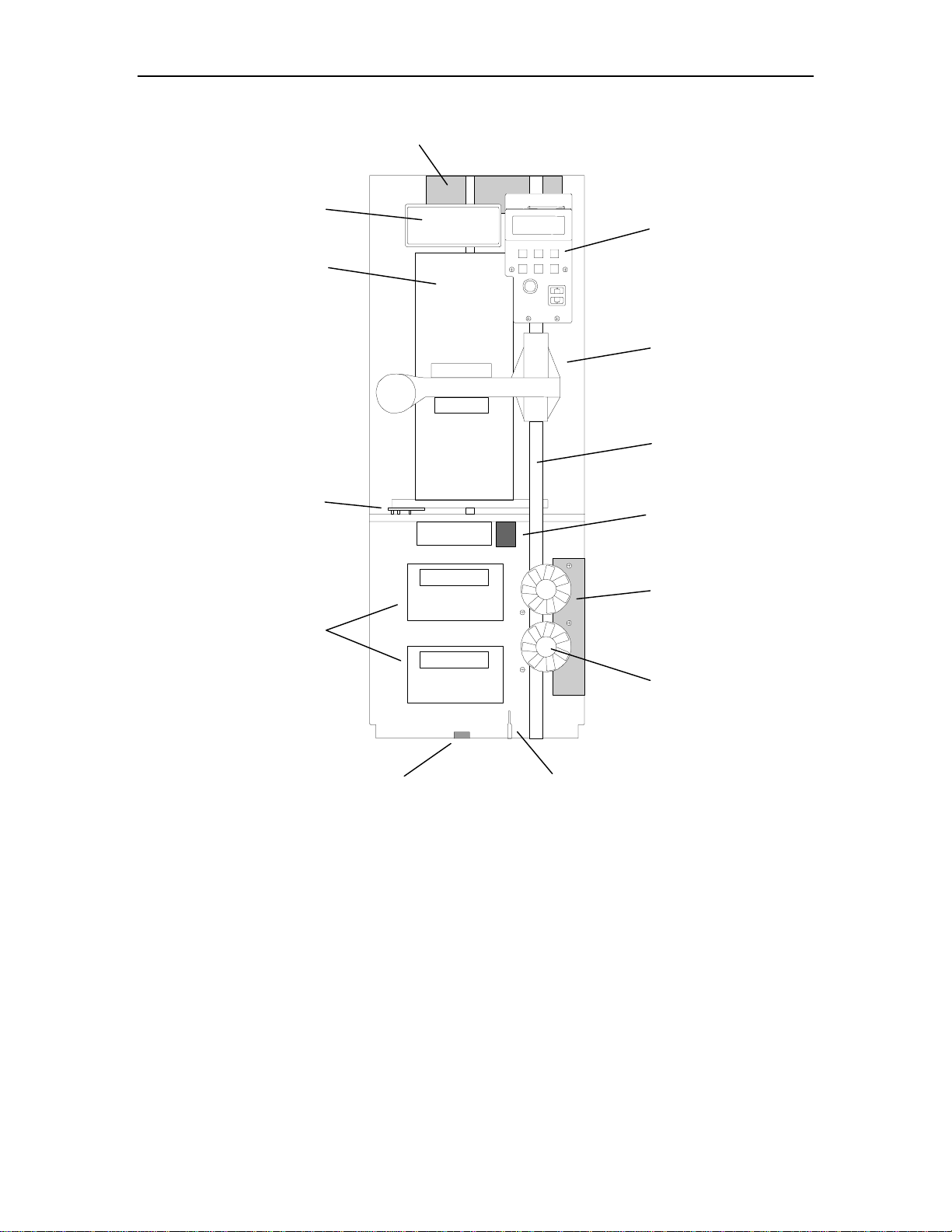
A
I/O Port Front Opening
Carousel
Carousel PCB
Handler Power Suppl y
Control Panel
Carriage, Handler,
Gripper and
Barcode Reader
Front Guide Shaft
Carousel Motor
Tape Drives
Y-Clear
Emitter Assembly
Figure 2-4 Single Bay TLS Front View
Vertical (Y) Axis
Home Sensor Probe
Tape Drive
Power Supply
Cooling Fans
501090 Rev. F Description and Theory of Operation 2-9
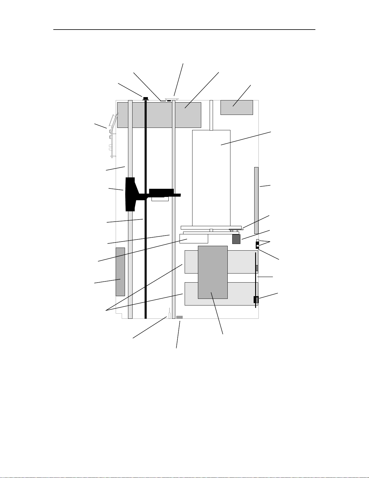
A
y
r
t
r
w
t
Y-Clear Detector PCBA
Spring Cup Assembl
and Plastic Washe
Control Panel
Front Guide Shaf
Carriage,
Handler, Gripper and
Barcode Reade
Vertical (Y) Axis
Lead Scre
Rear Guide Shaf
Y-Clear Detector
I/O Port Assembly
Handler Power Supply
Carousel
Executive PCBA
Carousel PCBA
Carousel Motor
SCSI Connectors
Private Slot
Cooling Fans
Tape Drives
Front Rear
Vertical (Y) Axis
Home Sensor Probe
Figure 2-5 Single Bay TLS Side View
Power Switch
Drive Bay PCBA
C Power
Receptacle
Tape Drive Power Supply
Y-Clear Emitter Assembly
2-10 Description and Theory of Operation 501090 Rev. F
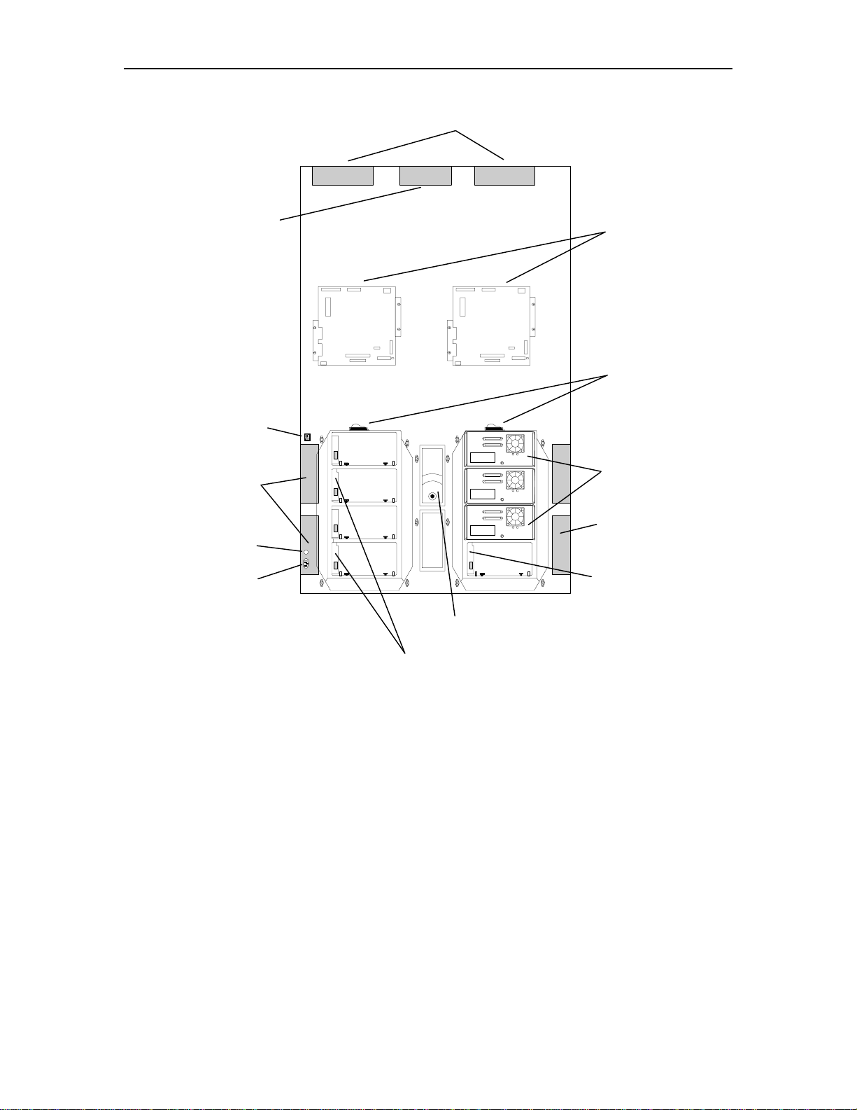
r
Blower Power Supply
Power Switch
Tape Drive
Power Supplies (4)
Handler Power Supplies (2)
Left Side Right Side
Executive PCBAs (2)
SCSI Connectors
Tape Drives
(8) Maximum
Fuse
AC Powe
Receptacle
Figure 2-6 Dual Bay TLS Rear View
Tape Drive
Power Supplies (4)
Drive Bay PCBAs (4)
Blower
Drive Bay PCBAs (4)
501090 Rev. F Description and Theory of Operation 2-11
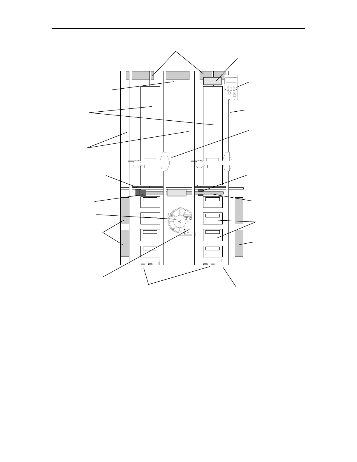
y
r
r
A
Blower Power Suppl
Carousels
Supporting Guide Shaft (2)
Carousel PCBA (2)
Shuttle Moto
Blowe
Handler Power Supplies (2)
Left
Side
Right
Side
I/O Port Front Opening
Control Panel
Front Guide Shaft (2)
Carriage, Handler,
Gripper and
Barcode Reader (2)
Carousel Motor (2)
Shuttle Mechanism
Tape Drives (8)
Tape Drives
Power Supplies (2)
Blower PCB
Y-Clear Emitter Assembly (4)
Figure 2-7 Dual Bay TLS Front View
Tape Drives
Power Supplies (2)
Vertical (Y) Axis
Home Sensor Probe (2)
2-12 Description and Theory of Operation 501090 Rev. F

A
r
r
Spring Cup Assembly
and Plastic Washer (2)
Control Panel
Carriage, Handler, Grippe
and Barcode Reader (2)
Carousel PCBA (2)
Y-Clear Detector (2)
Front
Guide Shaft (2)
Supporting
Guide Shaft (2)
Shuttle Assembly
Y-Clear Detector PCBA
I/O Port Assembly
Handler Power Supply (2)
Carousel (2)
Executive PCBA (2)
Carousel Motor (2)
SCSI Connectors
Power Switch
Vertical (Y) Axis
Lead Screw (2)
Rear Guide Shaft (2)
Blowe
Front Rear
Vertical (Y) Axis
Home Sensor Probe (2)
Figure 2-8 Dual Bay TLS Side View
Tape Drive PCBA (4)
Fuse
C Power Receptacle
Tape Drives (8) Maximum
Tape Drive Power Supplies (4)
Y-Clear Emitter Assembly (4)
501090 Rev. F Description and Theory of Operation 2-13
r
r
r
y
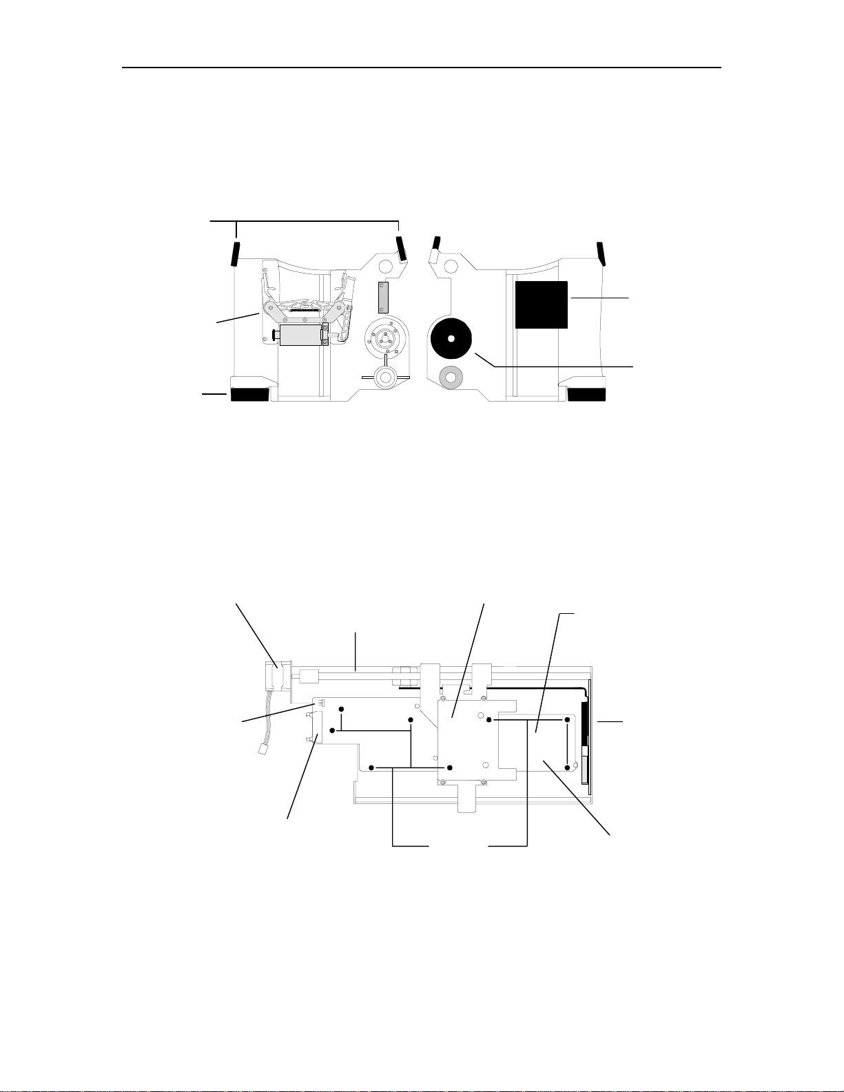
2.3.1 Handler
Figure 2-9 shows the major components of a TLS-5000/6000/8000 cartridge Handler.
The components of the left and right Handlers are identical.
Cartridge
Presence
Senso
Grippe
Assembl
Insertion
Z-Axis Moto
Top View Bottom View
Barcode
Reader
Vertical
Z-Axis Motor
Figure 2-9 Handler – Top and Bottom Views
2.3.2 I/O Port Assembly
Figure 2-10 shows the major components of the I/O port assembly.
Motor Cable Plug
I/O Port Motor
I/O Port Lead Screw
I/O Port Cable Plug
I/O Port Slot
8 PCBA
Mounting Nuts
Note: The LED’s Cable Plug
is located under the
I/O Port PCBA.
I/O Port Door
I/O Port PCBA
Bottom View
Figure 2-10 I/O Port Assembly
2-14 Description and Theory of Operation 501090 Rev. F

2.3.3 Field-Replaceable Units (FRUs)
Many of the library's major components are available separately as Field-Replaceable
Units (FRUs). These components can be removed and replaced in the field by qualified
personnel. See Chapter
moval/replacement instructions.
Some FRUs can be added to a unit as an expansion item. The instructions for installing an expansion FRU for the first time, or for permanently removing an expansion
FRU are contained in Chapter
7 for a complete list of FRUs, their part numbers and re-
9.
501090 Rev. F Description and Theory of Operation 2-15
t
3. The Menu System
The Menu system allows the user to perform routine operations. It also allows a qualified individual to make configuration changes to the TLS and to perform diagnostics.
This chapter explains the Menu system, the types of information it presents, and how
to use it. Specific information about Configuration or Operation menu items can be
found in the TLS-5000/6000/8000 Installation and Operation Manual (Qualstar document number 501450).
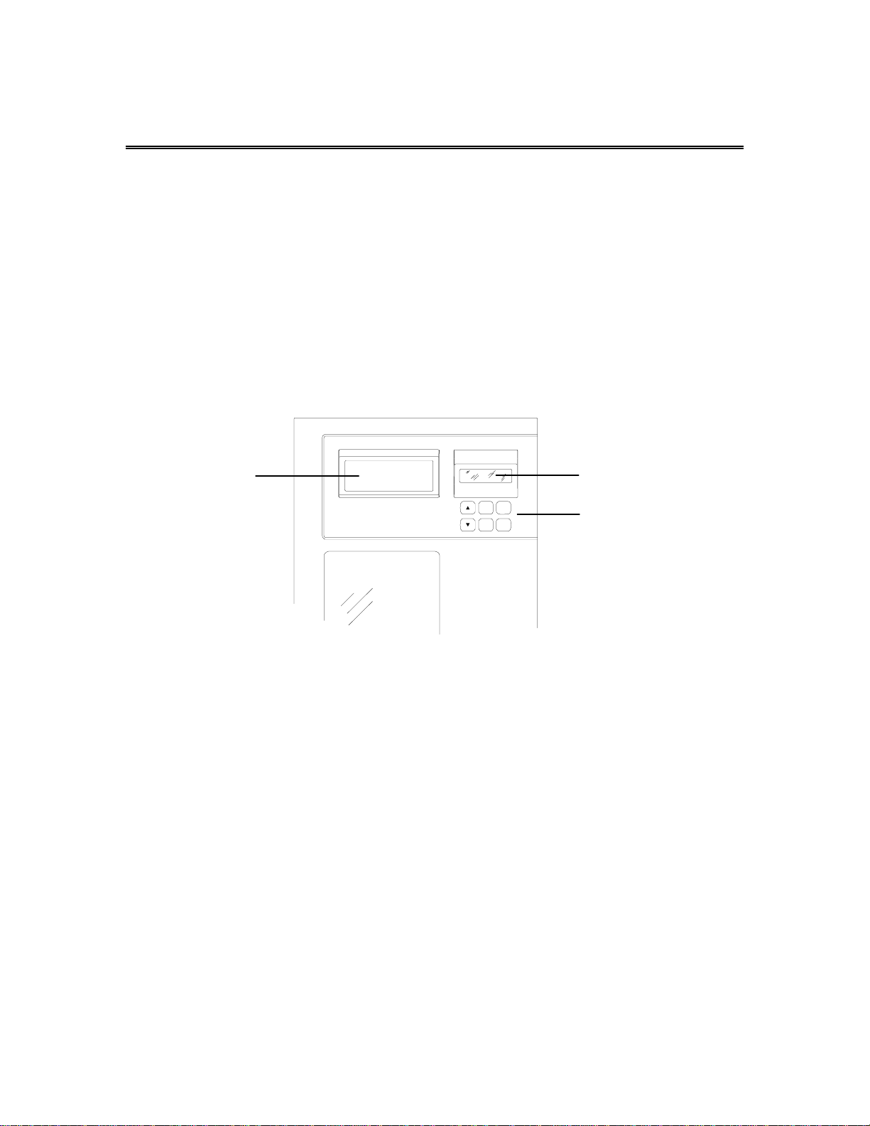
3.1 Using the Menu Control Keys
The control keys make it possible to point to a particular item and change or edit its
value, or to execute a command. The function of each control key is dependent upon
the location within the menu structure. The control keys are shown in
Figure 3-1.
I/O Por
EXIT
ENTER
MENU
Figure 3-1 TLS Control Keys
3.1.1 The MENU Control Key
Press the MENU key to enable the menu system. The menu system can be used without interrupting ongoing changer operations. If the Top Menu is not displayed, pressing the MENU key at any time always returns control to the Top Menu (
the Top Menu is displayed, press the MENU key to return to the Operating Display.
3.1.2 The V (UP) and W (DOWN) Control Keys
• While navigating through the menu system, the V (UP) and W (DOWN) keys move
the item pointer (right-pointing arrow) up and down the left column of the display.
The display automatically scrolls when necessary. The pointer identifies the current selection, as shown in Section
3.1.3 below.
Display
@
Control Keys
Figure 3-4). If
• If a value is highlighted, the V (UP) and W (DOWN) keys change the value of the
highlighted character or word. The DOWN key changes the character to the preceding character in the sequence (i.e., from B to A, or from 2 to 1). Pressing the V (UP)
key has the opposite effect.
501090 Rev. F The Menu System 3-1

• If a multiple choice value is highlighted, the V (UP) and W (DOWN) keys cycle
through the available choices.
• If the V (UP) or W (DOWN) key is pressed and held down, the control key's action
repeats at a rapid rate.
3.1.3 The ENTER Control Key
The ENTER key behaves as follows:
• If the item pointer is pointing at a sub-menu (indicated by a leading bullet), pressing ENTER will display the selected sub-menu.
O•••••Element Status
«•Display
•Find Label
INITIALIZE
Skip Labels: NO
INVALIDATE
SET DRIVES EMPTY
• If the item pointer points to a command such as POSITION (commands are always
displayed in all upper case letters), pressing ENTER executes the command.
O•••Position Handler
To Location:llllll
«POSITION
• When a command is executed, only the top line of the menu and the command
name (centered on the third line) are displayed for the duration of the command’s
execution.
O•••Position Handler
POSITION
• If a value contains an editable field, pressing ENTER highlights the first character
of the field by superimposing a flashing cursor over it. This indicates the Edit mode
is active and the value of the highlighted character can now be changed using the
V (UP) and W (DOWN) keys.
• In the Edit mode, pressing ENTER moves the cursor one character to the right. If
the cursor is over the rightmost character, pressing ENTER moves it back around
to the leftmost character. The action repeats if the ENTER key is held down.
• If a value contains a multiple-choice field, pressing ENTER highlights the field by
superimposing a flashing cursor over it. Pressing ENTER again has no effect.
3-2 The Menu System 501090 Rev. F
 Loading...