

Qualstar RLS-5244, RLS-4124, RLS-6227, RLS-8116, RLS-8202 Technical & Service Manual
...
RLS-8000
Tape Library
Technical
Service Manual
501510 Rev. S


501510 Rev. S iii
Firmwarethe firmwarethe RLS firmwaredifferent part numbers or firmwareQualstarTechnical Supportfirmware
Copyright Notice
Copyright© 2011 by Qualstar Corporation — All Rights Reserved
Information contained in this document is copyrighted by Qualstar Corporation. It is
intended for use by Qualstar’s customers and prospective customers to evaluate, integrate, operate and maintain Qualstar products. Customers and prospective customers
may reproduce this document as needed for these uses. Reproduction in whole or in
part for any other use or by any other party is prohibited without prior written permission from Qualstar Corporation.
Every effort has been made to keep the information contained in this document current and accurate as of the date of publication or revision. However, no guarantee is
given or implied that the document is error-free or that it is accurate with regard to
any specification. Qualstar reserves the right to modify product designs and specifications without notice.
Qualstar and the Qualstar logo are registered trademarks of Qualstar Corporation.
Other trademarks are the property of their respective owners.

iv 501510 Rev. S
Notices
Qualstar products are covered by one or more of the following patents:
6,163,139 and 6,560,061. Other patents pending.
Qualstar equipment is manufactured from new parts, or new and used parts. In some
cases, Qualstar equipment may not be new and may have been previously installed.
Regardless, Qualstar’s warranty terms apply unless the equipment is specifically
identified by Qualstar as “used” or “refurbished”.
This equipment has been tested and found to comply with the limits for a Class A di gital device, pursuant to Part 15 of the FCC Rules. These limits are designed to provide reasonable protection against harmful interference when the equipment is ope rated in a commercial environment. This equipment generates, uses, and can radiate
radio frequency energy and, if not installed and used in accordance with the instruction manual, may cause harmful interference to radio communications. Operation of
this equipment in a residential area is likely to cause harmful interference in which
case the user will be required to correct the interference at his own expense. Shielded
cables are required for this device to comply with FCC Rules. Use shielded cables
when connecting this device to others.
European Union Directive 89/336/EEC and Standard EN55022
(Electromagnetic Compatibility)
Warning
This is a Class A product. In a domestic environment this product may cause radio
interference in which case the user may be required to take adequate measures.
European Directive on Waste Electrical and Electronic Equipment (WEEE)
Qualstar encourages its customers to use current recycling practices in order to reduce the burden that waste electronic products place on the environment.
If you are retiring a fully functional tape library, you are encouraged to transfer the
functional unit to a new user, thereby extending the useful life of the tape library.
The manufacture of all products requires the consumption of energy. By extending
the life of the tape library, energy is conserved.
In accordance with environmental directives that are being implemented in many
countries (refer to the European Directive on Waste Electrical and Electronic Equipment - WEEE) Qualstar provides customers with “End of Life Instructions” that iden-

501510 Rev. S v
tify the process for recycling the materials and components that make up a Qualstar
tape library.
End of Life Instructions
Tools required
• P1 and P2 Phillips head screwdrivers
• T20 Torx head screwdriver
• Hex head (Allen) wrench/driver set
• 1/4-inch hex nut driver
Disassembly procedure
1. Remove door.
2. Remove top panel.
3. Remove side external panels.
4. Remove internal subassemblies.
Items recyclable using conventional methods
• Aluminum: Door, exterior panels, frame, robotics
• Stainless steel: Robot guides
• Steel: Some frames, fasteners
• Plastic: Window, cartridge magazines, tape cassettes
• Copper: Internal wiring, motors, SCSI cables
• Paper: Manuals
Items requiring special disposal due to lead-based solder
• Printed Circuit Boards: Controller, miscellaneous small printed circuit
boards
Items that may have salvage or resale value
• Tape drives
• EMI line power filter
Reduction of Hazardous Substances (RoHS)
Qualstar is committed to the implementation of RoHS (Restriction of the use of certain hazardous substances in electrical and electronic equipment) in accordance with

vi 501510 Rev. S
the European Directive. The effectivity date for compliance is July 1, 2006, at which
time Qualstar will certify that its Tape Library products are compliant with the RoHS
standard. With the exception of Lead Based Solder, Qualstar will certify that its
products are free of all other substances listed in the Directive.
Qualstar Tape Libraries fall under the category of “Information Technology Storage
Array Systems” for which the RoHS Directive provides for a lead solder exemption.
Insofar as lead free solders are new to the electronics industry and no quality or reliability data is available, Qualstar will invoke the lead based solder exemption until
such time as industry data verifies that lead free solders are capable of meeting or e xceeding the documented reliability and quality standards achieved with lead based
solders.
Until such time as Qualstar replaces lead based solder with lead free solder, effected
subassemblies must be disposed of appropriately.
Technical Support Information
The best source for service-related information is your system reseller. Alternately,
the Qualstar Technical Support Department can be reached Monday through Friday,
between the hours of 6:30 A.M. and 5:00 P.M. Pacific Time, at:
Qualstar Corporation
130 W. Cochran St; Suite C
Simi Valley, CA 93065
Attn: Technical Support
Phone: (877) 444-1744, (805) 583-7744
Monday – Friday 7:00 A.M.. to 4:00 P.M. PST
E-Mail support@qualstar.com
E-Mail: sales@qualstar.com
Web: www.qualstar.com

501510 Rev. S vii
Table of Contents
1. Introduction ................................................................................................................... 1-1
1.1 Who Should Read This Manual ................................................................................... 1-1
1.2 Important Safety Information ..................................................................................... 1-3
1.3 Lithium Battery ............................................................................................................ 1-4
2. Description and Theory of Operation ..................................................................... 2-1
2.1 Models ........................................................................................................................... 2-1
2.2 General Description ...................................................................................................... 2-6
2.2.1 Motion Systems ..................................................................................................... 2-6
2.2.2 Sensors ................................................................................................................... 2-7
2.2.3 Barcode Reader .................................................................................................... 2-10
2.2.4 Barcode Labels ..................................................................................................... 2-10
2.2.5 Capacity on Demand (COD) ............................................................................... 2-10
2.3 Component Identification .......................................................................................... 2-11
2.3.1 RLS Models .......................................................................................................... 2-11
2.3.2 Handler ................................................................................................................ 2-12
2.3.3 Field-Replaceable Units (FRUs) ......................................................................... 2-13
3. The Operator Interface ............................................................................................... 3-1
3.1 The Door Lock ............................................................................................................... 3-1
3.2 Using the Menu System ............................................................................................... 3-1
3.2.1 The MENU Control Key ........................................................................................ 3-2
3.2.2 The (UP) and (DOWN) Control Keys............................................................. 3-2
3.2.3 The ENTER Control Key ...................................................................................... 3-3
3.2.4 The EXIT Control Key........................................................................................... 3-3
3.2.5 The (Daisy) Key ................................................................................................ 3-4
3.3 Quick Operation Menu ................................................................................................. 3-4
3.3.1 OPEN & PARK LEFT command .......................................................................... 3-4
3.3.2 OPEN & PARK RIGHT command........................................................................ 3-5
3.3.3 OPEN VIOP (n) command .................................................................................... 3-5
3.3.4 PARK LEFT command .......................................................................................... 3-5
3.3.5 PARK RIGHT command ....................................................................................... 3-5
3.3.6 (UN)LOAD LIBRARY command .......................................................................... 3-6
3.3.7 The Status LEDs ................................................................................................... 3-7
3.4 The Top Menu ............................................................................................................... 3-7
3.5 Menu Elements ............................................................................................................. 3-8
3.5.1 Menu Items ............................................................................................................ 3-8
3.5.2 Values ..................................................................................................................... 3-9

viii 501510 Rev. S
3.5.3 Location Designators ........................................................................................... 3-10
3.5.4 Editing Values ..................................................................................................... 3-11
3.6 The Menu Hierarchy .................................................................................................. 3-13
3.7 Displaying the RLS Firmware Revision .................................................................... 3-14
3.8 Alerts/Faults ............................................................................................................... 3-14
3.9 Dynamic Menus and Menu Items.............................................................................. 3-15
4. The Maintenance Menu ............................................................................................... 4-1
4.1 The Maintenance menu ................................................................................................ 4-3
4.2 The Maintenance\Display Prevents status screen .................................................... 4-3
4.3 The Maintenance\Display Revision status screen ..................................................... 4-4
4.4 The Maintenance\Display Stats. status screen ......................................................... 4-4
4.5 The Maintenance\Display Voltage status screen ...................................................... 4-5
4.6 The Maintenance\Fibre Channel menu ..................................................................... 4-6
4.7 The Maintenance\Fibre Channel\Info status screen ................................................ 4-6
4.8 The Maintenance\Log menu ....................................................................................... 4-8
4.8.1 Introduction ........................................................................................................... 4-8
4.8.2 Data Logging – General Description .................................................................... 4-9
4.9 The Maintenance\Log\Display\Entry menu .......................................................... 4-10
4.10 The Maintenance\Test Inventory menu ................................................................... 4-11
4.11 The Maintenance\Test Keyboard status screen ...................................................... 4-11
4.12 The Maintenance\Test LC Display status screen .................................................... 4-13
5. The Private Menu ......................................................................................................... 5-1
5.1 Introduction .................................................................................................................. 5-3
5.2 Security Locks ............................................................................................................... 5-3
5.2.1 Door Lock ............................................................................................................... 5-3
5.2.2 Master Lock ........................................................................................................... 5-4
5.2.3 Disabling the Master Security Lock ..................................................................... 5-4
5.3 Enabling the Private Menu .......................................................................................... 5-6
5.3.1 Access ..................................................................................................................... 5-6
5.3.2 Setting a Password ................................................................................................ 5-6
5.3.3 Clearing the Password .......................................................................................... 5-9
5.4 The Private Menu ....................................................................................................... 5-10
5.4.1 The Private\CALIBRATE command ................................................................. 5-10
5.4.2 The Private\CLEAR ACCESS command .......................................................... 5-12
5.4.3 The OPEN VIOP WINDOW command .............................................................. 5-12
5.4.4 The REBOOT command ...................................................................................... 5-12
5.4.5 The RESET SCSI BUS command ....................................................................... 5-12
5.4.6 The Private\Cabling status screen .................................................................... 5-13
5.4.7 The Private\Calibration status screen .............................................................. 5-13
5.4.8 The Private\Configuration menu ...................................................................... 5-14

501510 Rev. S ix
5.4.9 The Private\Control Panel status screen .......................................................... 5-17
5.4.10 The Private\Display A/D status screen ............................................................. 5-17
5.4.11 The Private\Display Locations Menu ................................................................ 5-18
5.4.12 The Private\Display Positions status screen .................................................... 5-19
5.4.13 The Private\DriveBay status screen ................................................................. 5-20
5.4.14 The Private\Drive Bay\Alarm Limits status screen ........................................ 5-21
5.4.15 The Private\Drive Bay\C? menu ...................................................................... 5-21
5.4.16 The Private\Drive Bay\C?\Carrier status screen ........................................... 5-23
5.4.17 The Private\Drive Bay\C?\DIA status screen ................................................. 5-24
5.4.18 The Private\Drive Bay\Power ? status screen ................................................. 5-25
5.4.19 The Private\Executive status screen ................................................................. 5-26
5.4.20 The Private\Magazine menu.............................................................................. 5-27
5.4.21 The Private\ Sensors status screen ................................................................... 5-28
6. Troubleshooting ............................................................................................................ 6-1
6.1 Faults without Fault Messages ................................................................................... 6-1
6.1.1 When the power is turned on: no motion occurs, the LCD does not illuminate,
the three power-indicating LEDs on the IPM (rear of RLS) are dark. ............................. 6-1
6.1.2 When the power is turned on: no motion occurs, the LCD does not illuminate,
the +24V LED on the IPM (rear of RLS) blinks. ................................................................ 6-1
6.1.3 When the power is turned on: the LCD is illuminated and shows the library
model number, no errors messages are displayed, and nothing moves. .......................... 6-1
6.1.4 When the power is turned on: the Handler moves normally and the LCD is
illuminated, but it does not show text. ............................................................................... 6-2
6.1.5 The Barcode Reader does not read barcode labels reliably. ............................... 6-2
6.1.6 After Installing a Tape Drive, it Fails to Appear in the Menu System. ............. 6-2
6.2 POST (Power On Self Test) Fault Messages ............................................................... 6-2
6.2.1 BCR Failed (BCR is the Barcode Reader) ............................................................ 6-3
6.2.2 BCR Misconfigured (BCR is the Barcode Reader) .............................................. 6-3
6.2.3 Calibration Req’d ................................................................................................... 6-3
6.2.4 Not Configured ...................................................................................................... 6-3
6.2.5 Carousel Failed, Carousel Jammed...................................................................... 6-3
6.2.6 Array Failed, Array Jammed ................................................................................ 6-3
6.2.7 Gripper Homing Failed ......................................................................................... 6-3
6.2.8 X Failed to Home ................................................................................................... 6-3
6.2.9 Z Failed to Home ................................................................................................... 6-4
6.2.10 No Drivebay Found ............................................................................................... 6-4
6.2.11 No Carriage Found ................................................................................................ 6-4
6.2.12 No Sensor Pcb Found ............................................................................................ 6-4
6.2.13 No Carousel Found ................................................................................................ 6-4
6.2.14 No Storage Array ................................................................................................... 6-4
6.3 Operating Fault Messages ........................................................................................... 6-6

x 501510 Rev. S
6.3.1 Pick Failed ............................................................................................................. 6-6
6.3.2 Place Failed ............................................................................................................ 6-6
6.3.3 Carousel Failed, Carousel Jammed...................................................................... 6-6
6.3.4 Array Failed, Array Jammed ................................................................................ 6-6
6.3.5 X Axis Jammed ...................................................................................................... 6-6
6.3.6 X-Axis Obstructed ................................................................................................. 6-6
6.3.7 Z-Axis Jammed ...................................................................................................... 6-7
6.3.8 Z-Axis Obstructed .................................................................................................. 6-7
6.3.9 Handler Fault ........................................................................................................ 6-7
6.3.10 Left Fan Failed or Right Fan Failed .................................................................... 6-7
6.3.11 Left Supply Fail or Right Supply Fail .................................................................. 6-7
6.3.12 Fan Failed .............................................................................................................. 6-8
6.3.13 Supply Failed ......................................................................................................... 6-8
6.4 Operating Error Messages ........................................................................................... 6-8
6.4.1 Gripper Full ........................................................................................................... 6-8
6.4.2 No Target Magazine .............................................................................................. 6-8
6.4.3 No Target Drive ..................................................................................................... 6-8
6.4.4 Target Full ............................................................................................................. 6-8
6.4.5 Source Empty ......................................................................................................... 6-8
6.4.6 No Source Magazine .............................................................................................. 6-8
6.4.7 No Source Drive ..................................................................................................... 6-9
6.4.8 Tape Not Ejected ................................................................................................... 6-9
6.4.9 The Door is Locked ................................................................................................ 6-9
6.4.10 The Door is Open ................................................................................................... 6-9
6.5 Calibration Fault Messages ......................................................................................... 6-9
6.5.1 Calibration Fault ................................................................................................... 6-9
6.5.2 Failed No Magazine ............................................................................................... 6-9
6.5.3 Failed, Remove Cart .............................................................................................. 6-9
6.5.4 Failed Gripper Full ................................................................................................ 6-9
6.5.5 Calibration Failed ................................................................................................ 6-10
6.5.6 Opto Cal Failed .................................................................................................... 6-10
7. Field–Replaceable Units (FRUs) ............................................................................... 7-1
7.1 Introduction .................................................................................................................. 7-1
7.2 Field Upgrades .............................................................................................................. 7-5
7.3 Required Tools and Materials ...................................................................................... 7-7
7.4 Opening the Front Panel/Door..................................................................................... 7-8
7.5 Rack-Mounted Libraries .............................................................................................. 7-9
7.5.1 Extending the RLS from the Rack ..................................................................... 7-10
7.5.2 Retracting the RLS into the Rack ...................................................................... 7-10
7.6 Top Cover .................................................................................................................... 7-11

501510 Rev. S xi
7.6.1 Opening the Top Cover ....................................................................................... 7-11
7.6.2 Closing the Top Cover ......................................................................................... 7-11
7.7 Carriage Assembly...................................................................................................... 7-12
7.7.1 Carriage Assembly Removal Procedure ............................................................. 7-13
7.7.2 Carriage Assembly Replacement ........................................................................ 7-14
7.8 Carousel Assembly ..................................................................................................... 7-15
7.8.1 Carousel Removal ................................................................................................ 7-15
7.8.2 Carousel Replacement ......................................................................................... 7-17
7.9 Storage Array .............................................................................................................. 7-18
7.9.1 Style A Chassis Storage Array Removal ............................................................ 7-19
7.9.2 Style A Chassis Storage Array Replacement ..................................................... 7-24
7.9.3 Style B Chassis Storage Array Removal ............................................................ 7-25
7.9.4 Style B Chassis Storage Array Replacement ..................................................... 7-28
7.10 Front Panel/Door Assembly (Bezel) ........................................................................... 7-29
7.10.1 Front Panel/Door Assembly Removal ................................................................ 7-29
7.10.2 Front Panel/Door Assembly Replacement ......................................................... 7-30
7.11 Tape Drive Assembly .................................................................................................. 7-33
7.11.1 Tape Drive Assembly Removal ........................................................................... 7-35
7.11.2 Tape Drive Assembly Replacement .................................................................... 7-35
7.11.3 Verifying a Tape Drive Assembly Installation .................................................. 7-37
7.11.4 Drive Fillers ......................................................................................................... 7-37
7.12 Serial Control Panel PCBA ........................................................................................ 7-38
7.12.1 Serial Control Panel PCBA Removal ................................................................. 7-39
7.12.2 Serial Control Panel PCBA Replacement .......................................................... 7-39
7.13 Drive Bay PCBA Assembly ........................................................................................ 7-41
7.13.1 Drive Bay PCBA Assembly Removal ................................................................. 7-42
7.13.2 Drive Bay Assembly Replacement ..................................................................... 7-49
7.14 Executive-XI PCBA .................................................................................................... 7-51
7.14.1 Executive-XI PCBA Removal .............................................................................. 7-51
7.14.2 Executive-XI PCBA Replacement ...................................................................... 7-53
7.15 Door Lock PCBA ......................................................................................................... 7-54
7.15.1 Door Lock PCBA Removal .................................................................................. 7-54
7.15.2 Door Lock PCBA Replacement ........................................................................... 7-55
7.16 X-Clear Emitter PCBA ............................................................................................... 7-55
7.16.1 X-Clear Emitter PCBA Removal ........................................................................ 7-55
7.16.2 X-Clear Emitter PCBA Replacement ................................................................. 7-56
7.17 Sensor Master and Slave Assemblies ........................................................................ 7-57
7.17.1 Sensor Master Assembly Removal ..................................................................... 7-58
7.17.2 Sensor Slave Assembly Removal ........................................................................ 7-59
7.17.3 Sensor Slave Assembly Replacement ................................................................. 7-60

xii 501510 Rev. S
7.17.4 Sensor Master Assembly Replacement .............................................................. 7-60
7.18 Drive Interface Adapter (DIA) ................................................................................... 7-61
7.18.1 Drive Interface Adapter Removal ...................................................................... 7-61
7.18.2 Drive Interface Adapter (DIA) Replacement ..................................................... 7-62
7.19 DFA (Direct Fibre Attach) Duplex Cable .................................................................. 7-63
7.19.1 DFA Duplex Cable Removal ............................................................................... 7-63
7.19.2 DFA Duplex Cable Replacement ........................................................................ 7-65
7.20 Interface Personality Module (IPM) .......................................................................... 7-65
7.20.1 IPM Removal ....................................................................................................... 7-66
7.20.2 IPM Replacement ................................................................................................ 7-66
7.21 Power Supplies ........................................................................................................... 7-67
7.21.1 Removal of a Single Power Supply Module ....................................................... 7-68
7.21.2 Replacement of a Single Power Supply Module ................................................ 7-68
7.21.3 Hot Removal of a Dual-Redundant Power Supply Module ............................... 7-68
7.21.4 Hot Replacement of a Dual-Redundant Power Supply Module ....................... 7-69
7.22 Fixed Slots ................................................................................................................... 7-69
7.22.1 Fixed Slot Removal .............................................................................................. 7-70
7.22.2 Fixed Slot Replacement ...................................................................................... 7-70
7.23 Air Filter ..................................................................................................................... 7-70
7.23.1 Air Filter Inspection ............................................................................................ 7-71
7.23.2 Air Filter Replacement ........................................................................................ 7-72
7.24 Calibration .................................................................................................................. 7-72
7.24.1 Calibration Setup ................................................................................................ 7-72
7.24.2 Calibration Initialization .................................................................................... 7-74
7.24.3 Calibration Completion ....................................................................................... 7-74
8. Firmware Updating ...................................................................................................... 8-1
8.1 Firmware Replacement ................................................................................................ 8-1
8.2 Determining the Current Firmware Revision ............................................................ 8-1
8.3 Firmware Update via the SCSI or Fibre Channel Interface ..................................... 8-2
8.4 Firmware Update via Q-Link ...................................................................................... 8-4
8.5 Firmware Update via Q-Conn ..................................................................................... 8-8
8.5.1 RS-232 Cable Wiring ............................................................................................. 8-8
8.5.2 RS-232 Serial Communications Parameters ....................................................... 8-8
8.5.3 User Terminal Software Setup Example ............................................................. 8-9
8.5.4 VT100 Terminal Emulation ................................................................................ 8-11
8.5.5 Remote Library Command Mode ....................................................................... 8-13
8.5.6 Xmodem Firmware Download <xdl> .................................................................. 8-13
9. RLS Expansions ............................................................................................................ 9-1
9.1 Introduction .................................................................................................................. 9-1
9.2 Model Expansions ......................................................................................................... 9-2

501510 Rev. S xiii
9.2.1 Installing a Model Expansion Kit ......................................................................... 9-2
9.2.2 Style A Chassis Storage Array Removal .............................................................. 9-3
9.2.3 Style A Chassis Storage Array Expansion Kit Installation ................................ 9-6
9.2.4 Style B Chassis Storage Array Removal .............................................................. 9-7
9.2.5 Style B Chassis Storage Array Expansion Kit Installation ................................ 9-9
9.2.6 Entering the Update Password .......................................................................... 9-11
9.2.7 Reconfiguring the Model Number ...................................................................... 9-11
9.2.8 Recalibrating the Unit ........................................................................................ 9-12
9.2.9 Clearing the Password ........................................................................................ 9-12

xiv 501510 Rev. S
This page left blank intentionally.

501510 Rev. S Introduction 1-1
1. Introduction
1.1 Who Should Read This Manual
This Technical Service Manual is for RLS service personnel. It describes the Maintenance Menu, the Private Menu and instructions for removing and replacing Field Replacement Units (FRU's). It also contains troubleshooting procedures and after–
maintenance testing procedures.
The following topics are covered in the RLS-8000 Tape Library Installation and Operation manual (Qualstar document number 501500):
• Unpacking Instructions
• Control Panel
• Menu System
• System Configuration
• System Operation
• Preventative Maintenance
• Repacking Instructions
For information about the SCSI interface, or other information outside the scope of
this manual, please refer to the appropriate documents listed below.
Subject
Document
Qualstar
Documen
t
Number
Specifications
RLS-8000 Product Specification
501490
Installation and Operation
RLS-8000 Installation and Operation Manual
501500
ADI Interface Quick Start
Product Application Note
PAN-025
Approved Data Cartridges
Product Information Note
PIN-038
Barcode Label Specifications
Product Information Note
PIN-040
Capacity on Demand
Ordering & Installing Capacity on Demand
PIN-044
SAS Cable and HBA Considerations
Product Information Note
PIN-046
SCSI Medium-changer Information
RLS SCSI-2 Interface Reference
501551
SCSI-2 Specification
ANSI X3.131-1994
N/A
SCSI SPI-3 Specification
NCITS T10 Project 1302D
N/A

1-2 Introduction 501510 Rev. S
Table 1-1 Applicable Documents

501510 Rev. S Introduction 1-3
Although Qualstar has made every effort to insure the accuracy of the information
contained in this manual, no guarantee is expressed or implied that the manual is
error-free. Qualstar reserves the right to make changes at any time without prior notification.
The Qualstar RLS is a sophisticated, state-of-the-art computer peripheral. It may only be serviced by an authorized service technician who is experienced with the operation and maintenance of tape libraries, and only after reading and understanding this
manual and the RLS Installation and Operation Manual.
1.2 Important Safety Information
All of the operating instructions and maintenance procedures in Qualstar manuals
must be followed to prevent personal injury or damage to the equipment. In the interests of safety, there are two kinds of warnings used in Qualstar documents, as shown
below.
DANGER
PERSONAL INJURY MAY RESULT IF YOU DO NOT FULLY COMPLY WITH THE
HANDLING, OPERATING, OR SERVICE INSTRUCTIONS FOUND IN A DANGER
PARAGRAPH.
GEFAHR
UNSACHGEMAESSE BENUTZUNG, BEDLENUNG ODER RAPARATUR
AUFGRUND VON NICHTBEGEFAHR DER SICHERHEITSANWEISUNG KANN ZU
VERIET-ZUNGEN FUEHREN.
CAUTION
EQUIPMENT DAMAGE OR LOSS OF DATA may result if you do not fully comply with the handling, operating, or service instructions found in a CAUTION
paragraph.

1-4 Introduction 501510 Rev. S
In addition, useful information and tips may be found throughout the document in
the following formats:
NOTE
SPECIAL ATTENTION to explanatory statements found in a NOTE paragraph will help
you avoid mistakes and/or save time.
NOTICE
A NOTICE box contains additional important information not covered by the
other three types of special text: DANGER, CAUTION, or NOTE.
1.3 Lithium Battery
Please observe the following information when repairing the unit.
DANGER
U9, A DALLAS SEMICONDUCTOR CORPORATION DS1225AB OR A SGSTHOMPSON MICROELECTRONICS M48258X IC ON THE EXECUTIVE PCBA
CONTAINS AN INTEGRAL LITHIUM BATTERY. AN EXPLOSION DANGER
EXISTS IF THE IC IS INCORRECTLY REPLACED. REPLACE THE IC ONLY WITH
THE SAME PART NUMBER, OR AN EQUIVALENT DESIGNATED BY THE
MANUFACTURER. DISPOSE OF THE USED IC ACCORDING TO THE
MANUFACTURER'S INSTRUCTIONS.
GEFAHR
DER U9, EIN DALLAS SEMICONDUCTOR CORPORATION DS1225AB ODER
EIN A SGS-THOMPSON MICROELECTRONICS M48258X IC AUF DEM
EXECUTIVE BOARD ENTHAELT EINE INTEGRIERTE LITHIUM BATTERIE. WENN
DIESE UNSACHGEMAESS AUSGETAUSCHT WIRD, BESTEHT EXPLOSIONS
GEFAHR. DER IC DARF NUR DURCH EINEN ARTIKEL MIT DER SELBEN
ARTIKELNUMMER, BZW, MIT EINEM VERGLEICHBAREN ARTIKEL LAUT

501510 Rev. S Introduction 1-5
HERSTELLER ANGABE ERSETZT WERDEN. DIE ENTSORGUNG DES ALTEN IC’S
DARF NUR GEMAESS HERSTELLERANGABEN ERFOLGEN.

1-6 Introduction 501510 Rev. S
This page left blank intentionally.
501510 Rev. S Description and Theory of Operation 2-1
2. Description and Theory of Operation
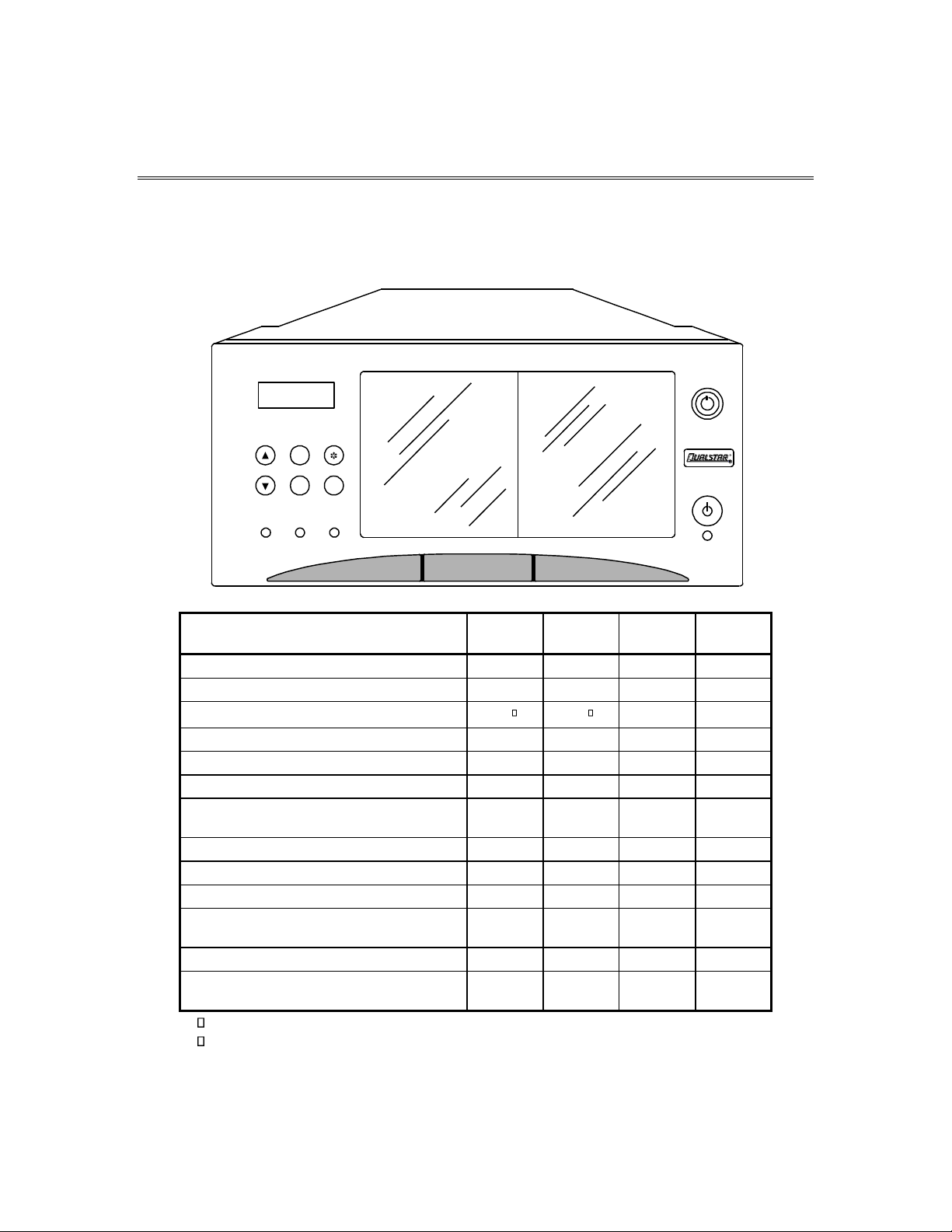
2.1 Models
EXIT
ENTER
MENU
READY
FAULT
BUSY
R
FEATURE/MODEL
4124
4221
4445
4470
Tape Technology
AIT
AIT
AIT
AIT
Maximum No. of Drives
1 2 4
4
Total Cartridge Capacity
24
22
45
70
Number of Magazines
4 4 9
14
Cartridges per Magazine
5 5 5
5
Barcode Reader
Optional
Optional
Optional
Optional
LVD/SE SCSI
Interface Personality Module (IPM)
N/A
Standard
Standard
Standard
2-GB Fibre Channel Interface (IPM)
N/A
Optional
Optional
Optional
Q-Link Remote Manager
Standard
Standard
Standard
Standard
Quick swap tape drive carriers
N/A
Standard
Standard
Standard
Buffered Drive Interface Adapters (BDIAs)
for Hot Swappable Tape Drives
N/A
Optional
Optional
Optional
Standard Power Module Output (watts)
125
125
250
250
Redundant, Hot-Swappable Power Modules
(Dual 250-watt modules)
N/A
N/A
Optional
Optional
Includes 4 fixed cartridge storage locations
Includes 2 fixed cartridge storage locations
Table 2-1 RLS-4000 Models, Features and Options
2-2 Description and Theory of Operation 501510 Rev. S
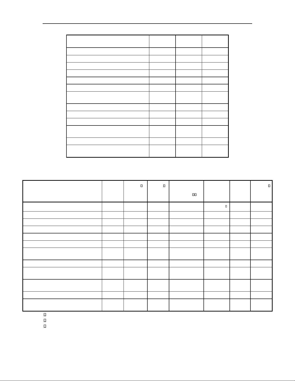
FEATURE/MODEL
5116
5244
6227
Tape Technology
SAIT
SAIT
Super DLT
Maximum No. of Drives
1 2 2
Total Cartridge Capacity
16
44
27
Number of Magazines
4
11
9
Cartridges per Magazine
4 4 3
Barcode Reader
Optional
Optional
Optional
LVD/SE SCSI
Interface Personality Module (IPM)
N/A
Standard
Standard
2-GB Fibre Channel Interface (IPM)
N/A
Optional
Optional
Q-Link Remote Manager
Standard
Standard
Standard
Quick swap tape drive carriers
N/A
Standard
Standard
Buffered Drive Interface Adapters (BDIAs) for Hot Swappable Tape Drives
N/A
Optional
Optional
Standard Power Module Output (watts)
125
250
250
Redundant, Hot-Swappable Power Modules (Dual 250-watt modules)
N/A
Optional
Optional
Table 2-2 RLS-5/6000 Models, Features and Options
FEATURE/MODEL
8116
8202
8204
RLS-
8204D
8216H
8236
8236D
Tape Technology
LTO
LTO
LTO
LTO
LTO (HH)
LTO
LTO
Maximum No. of Drives
1 2 2 2 2 2 2
Total Cartridge Capacity
1
12-36
12-44
12-44
16
36
36
Number of Magazines
16
3-9
3-11
3-11
4 9 9
Cartridges per Magazine
4 4 4 4 4 4 4
Barcode Reader
Optional
Optional
Optional
Standard
Optional
Optional
Optional
LVD/SE SCSI
Interface Personality Module (IPM)
N/A
Standard
Standard
Standard
Standard
Stand-
ard
Standard
2-GB Fibre Channel Interface (IPM)
N/A
Optional
Optional
Optional
Optional
Optional
Optional
Q-Link Remote Manager
Standard
Standard
Standard
Standard
Standard
Stand-
ard
Standard
Quick swap tape drive carriers
N/A
Standard
Standard
Standard
Standard
Stand-
ard
Standard
Standard Power Module Output (watts)
125
250
250
250
160
250
250
Redundant, Hot-Swappable Power
Modules (Dual 250-watt modules)
N/A
Optional
Optional
Optional
N/A
Optional
Optional
Features field-upgradeable Capacity on Demand
“D” models support LTO DFA fibre channel tape drives
HH = Half-High tape drives
Table 2-3 RLS-8000 Models, Features and Options (continued below)

501510 Rev. S Description and Theory of Operation 2-3
2-4 Description and Theory of Operation 501510 Rev. S
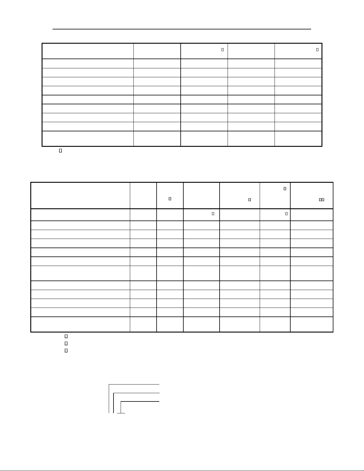
FEATURE/MODEL
RLS-8216C
RLS-8216CD
RLS-8236C
RLS-8236CD
Tape Technology
LTO
LTO
LTO
LTO
Maximum No. of Drives
2 2 2
2
Total Cartridge Capacity
16
16
36
36
Number of Magazines
4 4 9
9
Cartridges per Magazine
4 4 4
4
Barcode Reader
Standard
Standard
Standard
Standard
Q-Link Remote Manager
Standard
Standard
Standard
Standard
Quick swap tape drive carriers
Standard
Standard
Standard
Standard
Standard Power Module Output
(watts)
160
160
160
160
“D” models support LTO DFA fibre channel tape drives
Table 2-4 RLS-8000 Models, Features and Options (continued below)
FEATURE/MODEL
8244
8244D
RLS-
8444H
RLS-
8444D
8404H
RLS-
8404D
Tape Technology
LTO
LTO
LTO (HH)
LTO
LTO (HH)
LTO
Maximum No. of Drives
2 2 4 4 4
4
Total Cartridge Capacity
44
44
44
44
12-44
12-44
Number of Magazines
11
11
11
11
3-11
11
Cartridges per Magazine
4 4 4 4 4
4
Barcode Reader
Optional
Optional
Standard
Standard
Optional
Standard
LVD/SE SCSI
Interface Personality Module (IPM)
Standard
Standard
Standard
Standard
Standard
Standard
2-GB Fibre Channel Interface (IPM)
Optional
Optional
Optional
Optional
Optional
Optional
Q-Link Remote Manager
Standard
Standard
Standard
Standard
Standard
Standard
Quick swap tape drive carriers
Standard
Standard
Standard
Standard
Standard
Standard
Standard Power Module Output (watts)
250
250
250
250
250
250
Redundant, Hot-Swappable Power
Modules (Dual 250-watt modules)
Optional
Optional
Optional
Optional
Optional
Optional
Features field-upgradeable Capacity on Demand
“D” models support LTO DFA fibre channel tape drives
HH = Half-High tape drives
Table 2-5 RLS-8000 Models, Features and Options
RLS-0000
Series Identifier
Maximum Number of Drives
Maximum Number of Cartridges in Magazines
501510 Rev. S Description and Theory of Operation 2-5
Figure 2-1 Model Number Identification Scheme
This manual applies to all models. The installation and operation of the various models is virtually identical. Differences among the models are noted where required.
EXIT
ENTER
MENU
READY
FAULT
BUSY
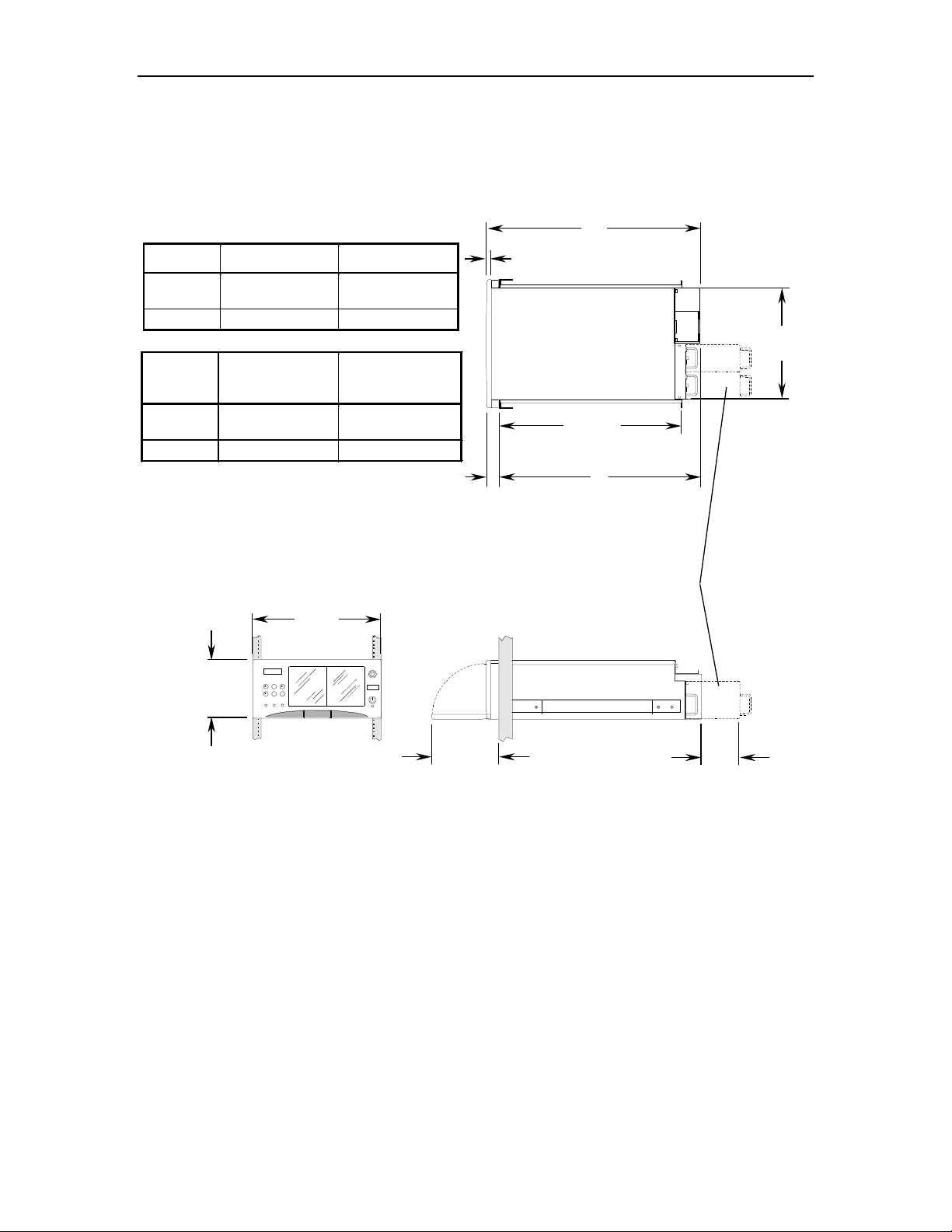
19.0”
48.3 cm
8.75”
22.2 cm
10.0”
25.4 cm
8.0”
20.3 cm
Dual-Redundant, Hot-Swappable
Power Supply Option
.7”
1.8 cm
A
B
16.6”
42.2 cm
2.0”
5.1 cm
C
(Rail Spacing)
Model
“A” Dimension
“B” Dimension
5116 &
XXX4
36.9” / 93.7 cm
34.9” / 88.6 cm
All Others
32.1” / 81.5 cm
30.1” / 76.4 cm
Model
“C” Dimension
Minimum
“C” Dimension
Maximum
5116 &
XXX4
27.5” / 69.9 cm
36.2” / 92.0 cm
All Others
22.0” / 55.9 cm
30.6” / 77.7 cm
Figure 2-2 RLS External Dimensions
These tape libraries are not intended for use in mobile applications. They were designed for use in an office environment.
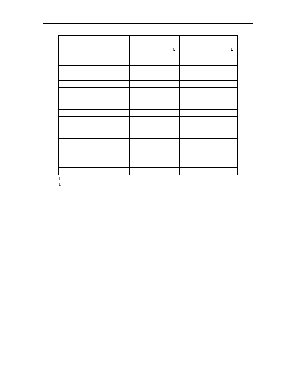
2-6 Description and Theory of Operation 501510 Rev. S
MODEL
NET WEIGHT
FULLY LOADED
(LBS / KG)
COMBINED
SHIPPING WEIGHT
(LBS / KG)
RLS-4124
61 / 28
81 / 37
RLS-4221
67 / 30
87 / 39
RLS-4445
87 / 39
107 / 49
RLS-4470
92 / 42
112 / 51
RLS-5116
108 / 49
138 / 63
RLS-5244
151 / 68
181 / 82
RLS-6227
97 / 44
119 / 54
RLS-8116
69 / 31
97 / 44
RLS-8202/8216C/8216CD
104 / 47
132 / 60
RLS-8236/8236C/8236CD/8236D
114 / 52
142 / 64
RLS-8204/8204D
147 / 67
177 / 80
RLS-8216H
70 / 32
98 / 44
RLS-8244/8244D
147 / 67
177 / 80
RLS-8404H/8404D
151 / 69
181 / 82
RLS-8444H/8444D
151 / 69
181 / 82
Includes a full complement of Tape Drives, magazines and tape cartridges
Not including tape cartridges
Table 2-6 RLS Weights
2.2 General Description
Models accommodate one or four tape drives and have removable magazines for tape
cartridge storage. There are models that utilize AIT, LTO, SDLT and SAIT tape technology. All units operate on internationally available AC power. Brushless motors are
used exclusively. All digital closed-loop servo systems use magnetic and optical position sensors. The servos automatically calibrate themselves, thus eliminating all electrical adjustments. Preventive maintenance is reduced to replacing the Air Filter,
when so prompted by the control panel display and removing debris inside the RLS.
2.2.1 Motion Systems
• On the RLS-4124, 4221, 5116, 8116 and 8216H a rotating carousel is utilized
to hold four magazines containing tape cartridges. The carousel rotates in
90-degree increments to present one magazine (or 5 tape cartridge slots)
to the robotic handler. The carousel rotates in either direction to minimize the access time to any data cartridge.
• All other models utilize a patented storage array that holds 9 magazines in
a rectangular array that is 2 magazines wide and 5 magazines deep. One of

501510 Rev. S Description and Theory of Operation 2-7
the possible 10 magazines is missing in order to facilitate movement of the
other 9. Due to its increased depth, the RLS-5244, 8204, 8204D, 8244, 8244D,
8404, 8404D, 8444 and 8444D have two more magazines (11 magazines out
of 12 positions). The magazines are identified MA through MI or MK and
the magazine in the right front corner is accessible by the Handler.
The RLS-4470 utilizes a patented storage array that holds 14 magazines in
a rectangular array that is 2 magazines wide and 8 magazines deep. Two
of the possible 16 magazines are missing in order to facilitate movement of
the other 14. The 14 magazines are identified MA through MN and the
magazine in the right front corner is accessible by the Handler.
The magazines in the storage arrays are shuffled around the racetracklike array in either direction. The direction of movement is chosen to minimize the time to access the desired magazine.
• The RLS utilizes a two-axis robotic cartridge handling mechanism that
moves cartridges between the storage slots and the Tape Drives. In the
unlikely event this assembly ever needs replacing, it can be accomplished
in less than 5-minutes.
All motion is powered by brushless DC motors turning precision leadscrews and drive shafts. Magnetic sensors provide position and velocity
feedback to the motors, while optical sensors provide absolute positional
information. This unique design produces optimum positioning accuracy,
reliability and long life. The servo systems are digital, self-calibrating and
never require mechanical adjustments.
2.2.2 Sensors
Optoelectronic Interrupters Sensors
These consist of an LED emitter and a Schmidt trigger optoelectronic sensor, which
produces a digital output indicating if it is blocked or not. Some consist of two loose
parts, and others have both parts integrated into one housing. These can only be used
at very short ranges, and must either be protected from ambient light, or be designed
to be fail-safe.
• X Home
This is an Opto switch pair located on the Carriage Emitter PCBA. The
signal feeds back to the Sensor Master PCBA. It is blocked when the carriage is far enough to the right of its travel to be in danger of actuating
the door-opening device. It is used for homing the X-axis during POST
(Power On Self Test), self-diagnostics, or calibration.
• Door Latched
This indicates that the front door is closed and latched. The sensor is located on and read by the front panel PCBA.
• IO Port Door Latched
This indicates that the IO Port door is closed and latched. The sensor is
located on and read by the front panel PCBA.

2-8 Description and Theory of Operation 501510 Rev. S
• Door Locked
This indicates that the door lock is fully turned to the locked position. The
sensor is located on the Door Lock Sensor PCBA and feeds back to the
Sensor Master PCBA.
• Carousel on Face
This indicates that the carousel is aligned on a face. The sensor is located
on the Carousel PCBA and it feeds back directly to the Executive PCBA.
• Drive Locked1 and 2
Located on the Drive Bay PCBA, it is used to sense that a drive is installed. These devices do not have Schmidt triggers as the others do, but
rather they have a phototransistor output.
Hall Effect Sensors
These are simple three-lead devices, which indicate the presence or direction of a local
magnetic field.
• Carousel Home
This sensor gives a once-around indication for the carousel, and is used to
find the home face of the carousel. It is located on the carousel PCBA, and
feeds back to the Executive PCBA. It looks for a magnet buried in the carousel platform.
• X Motor Phase A, B & C
These sensors are integral to the Brushless DC motors, and provide the
Executive PCBA with feedback for both commutation and position. They
route through the Carriage PCBA, the Interconnect PCBA, and finally to
the Executive PCBA. These sensors provide continuous incremental position feedback so the library always knows where its carriage is.
• Z Motor Phase A, B & C
These sensors are integral to the Brushless DC motors, and provide the
Executive PCBA with feedback for both commutation and position. They
route through the Carriage PCBA, the Interconnect PCBA, and finally to
the Executive PCBA.
• Storage Array Index Sensor
This sensor is located on the Storage Array PCBA and senses a magnet
embedded in a cam to provide phasing information for the control system.
• Storage Array Home Sensor
These two sensors are located on the Storage Array PCBA and sense a
magnet on the bottom of car “A”, so the control system can identify which
car is the first one.
Modulated Optoelectronic Sensors
These are used where the range is greater that allowed by simple optoelectronic sensor pairs. These sensors consist of an LED emitter, which is modulated, and a detector, which was designed for remote control of consumer products. The detector looks
for a particular carrier frequency, which is modulated by a sub-carrier that would
normally carry data. In our application, we use it to detect the presence of the modulated signal, but impose no data on it. The part features an infrared filter, carrier and

501510 Rev. S Description and Theory of Operation 2-9
sub-carrier band selection, automatic gain control, and signal detection, which allow
it to run directly off a processor.
• Z Home
The detector is located on the Interconnect PCBA, and the emitter is located on the X Clear PCBA. Both devices are operated by the Sensor Master PCBA. The principle function is to detect when the Z axis of the carriage is back far enough to operate the door-opening mechanism, which is
very nearly all the way towards the front of the library. It is used for homing the Z-axis during POST (Power On Self Test), self-diagnostics, or calibration.
• Gripper Home
The detector is located on the Interconnect PCBA, and the emitter is located on the X Clear PCBA. Both devices are operated by the Sensor Master PCBA. The principle function is to detect when the grippers are all the
way open while the carriage is at the back of its travel. It is used for homing the gripper during POST (Power On Self Test), self-diagnostics, or calibration, and various times during fault recovery and in normal operation.
The grippers are driven by a step-motor, and there is no feedback to determine their position except this sensor.
• X Clear
The detector is located on the Interconnect PCBA, and the emitter is located on the X Clear PCBA. Both are operated by the Sensor Master PCBA.
The principle function is to detect an object unexpectedly obstructing the
“no man’s land” between the carriage and the cartridges. It is also used to
detect the presence of magazines in the carousel during inventory. The
other function is to sense if someone may have modified the inventory of
the library. If the front door or the IO Port access door is open, and the
beam becomes blocked, then the library assumes that the inventory information may have been compromised, so it will rescan the affected elements.
• Magazine Cartridge 1, 2, 3, 4 & 5
The emitters are located on the Sensor Slave PCBA, and the detectors are
located on the Sensor Master PCBA. These are operated by the Sensor
Master PCBA. They are used to detect cartridges in the magazine facing
the front door. During inventory, each face is turned to the front to present its cartridges to these sensors for detection. If a cartridge is present,
then the corresponding sensor beam will be blocked, and the library will
mark the location as occupied in its inventory data base.
• Fixed Cartridge 1, 2, 3 & 4
The emitters are located on the Sensor Slave PCBA, and the detectors are
located on the Sensor Master PCBA. These are operated by the Sensor
Master PCBA. They are used to detect cartridges in the fixed cartridge
storage slots. During inventory, if a cartridge is present, then the corresponding sensor beam will be blocked, and the library will mark the location as occupied in its inventory data base.

2-10 Description and Theory of Operation 501510 Rev. S
• Drive Cartridge 1 & 2
The emitters are located on the Sensor Slave PCBA, and the detectors are
located on the Sensor Master PCBA. These are operated by the Sensor
Master PCBA. They are used to detect cartridges in the Tape Drives. During inventory, if a cartridge is present, then the corresponding sensor
beam will be blocked, and the library will mark the location as occupied
in its inventory data base.
2.2.3 Barcode Reader
An integrated Barcode Reader (BCR) is optional on all RLS models. The BCR can
uniquely identify each barcode labeled cartridge, thus saving the system from reading
each cartridge in a Tape Drive. Preprinted barcode labels, which are both human- and
machine-readable, are available from a number of sources including Qualstar.
The Barcode Reader consists of an LED light source and a Charge-Coupled Device
(CCD) sensor (similar to that used in a video camera) and associated electronics. It is
mounted on the carriage and contains no moving parts. The Barcode Reader can scan
all cartridges within the RLS (except those loaded inside Tape Drives). Barcode data
is stored internally in the changer’s non-volatile RAM (the internal inventory database) and is available to the host computer upon request.
2.2.4 Barcode Labels
Pre-printed barcode labels, which are both human- and machine-readable, are available from a number of sources including Qualstar.
Barcode labels must conform to ANSI/AIM BCI-1995, Uniform Symbology Specification Code 39. Please refer to PIN-040 at www.qualstar.com (click on Support tab) for
more information.
By default, the RLS expects a modulus 43 check character at the end of each label.
The use of a check character helps assure that labels are read error-free. The RLS
configuration must be changed before using barcode labels without a check character.
All of the labels within the RLS must match the check character configuration: either
all with or all without a check character.
2.2.5 Capacity on Demand (COD)
The Capacity on Demand (COD) feature allows the storage capacity of RLS-8204,
8204D, 8404 and 8404D models to be field expanded from 12 tape cartridges up to 44
in increments of eight. The RLS-8202 may be expanded from 12 tape cartridges up to
36 in increments of eight. To order an upgrade kit, contact an authorized Reseller, or
Qualstar Sales at 805-583-7744 x 773. Necessary information about ordering and installing COD can be found in PIN-044 available at www.qualstar.com (click on the
Support tab).
 Loading...