

Qualstar RLS User Manual

The Tape Library ExpertsTM
RLS Series
Tape Libraries
Product Specification
501490 Rev. Q

Copyright Notice
Copyright© 2010 by Qualstar Corporation — All Rights Reserved
Information contained in this document is copyrighted by Qualstar Corporation. It is
intended for use by Qualstar's customers and prospective customers to evaluate,
integrate, operate and maintain Qualstar products. Customers and prospective
customers may reproduce this document as needed for these uses. Reproduction in
whole or in part for any other use or by any other party is prohibited without prior
written permission from Qualstar Corporation.
Every effort has been made to keep the information contained in this document
current and accurate as of the date of publication or revision. However, no guarantee
is given or implied that the document is error-free or that it is accurate with regard to
any specification.
Qualstar reserves the right to modify the design or specification without notice. This
specification may not be construed as a contractual obligation except as specifically
agreed to by Qualstar in writing at the time of order.
Qualstar and the Qualstar logo are registered trademarks of Qualstar Corporation.
Other trademarks are the property of their respective owners.
Notices
Qualstar products are covered by one or more of the following patents:
6,163,139 and 6,560,061. Other patents pending.
Qualstar equipment is manufactured from new parts, or new and used parts. In some
cases, Qualstar equipment may not be new and may have been previously installed.
Regardless, Qualstar’s warranty terms apply unless the equipment is specifically
identified by Qualstar as “used” or “refurbished”.
This equipment has been tested and found to comply with the limits for a Class A
digital device, pursuant to Part 15 of the FCC Rules. These limits are designed to
provide reasonable protection against harmful interference when the equipment is
operated in a commercial environment. This equipment generates, uses, and can
radiate radio frequency energy and, if not installed and used in accordance with the
instruction manual, may cause harmful interference to radio communications.
Operation of this equipment in a residential area is likely to cause harmful
interference in which case the user will be required to correct the interference at his
own expense. Shielded cables are required for this device to comply with FCC Rules.
Use shielded cables when connecting this device to others.
501490 Rev. Q i

For information about this product specification, please write or call Qualstar at:
QUALSTAR CORPORATION
3990-B Heritage Oak Court
Simi Valley CA 93063
FAX: (805) 583-7749
Phone: (805) 583-7744
E-Mail: sales@qualstar.com
www.qualstar.com
ii 501490 Rev. Q

Table of Contents
1. Introduction................................................................................................................... 1-1
1.1 Scope.............................................................................................................................. 1-1
1.2 Supplemental Documentation ..................................................................................... 1-1
2. Product Description..................................................................................................... 2-1
2.1 General Description...................................................................................................... 2-1
2.2 Standard Features Found in All Models..................................................................... 2-1
2.3 Optional Features Available on Most Models............................................................. 2-2
2.4 Models ........................................................................................................................... 2-3
2.5 Major Features.............................................................................................................. 2-4
2.5.1 Capacity on Demand ............................................................................................. 2-4
2.5.2 Cabinet ................................................................................................................... 2-4
2.5.3 Front Panel Components ...................................................................................... 2-4
2.5.4 Rear Panel Components........................................................................................ 2-6
2.5.5 Medium Changer Components............................................................................. 2-9
2.5.6 Barcode Labels..................................................................................................... 2-12
2.6 The SCSI Interface ..................................................................................................... 2-12
2.6.1 SCSI Connectors.................................................................................................. 2-12
2.6.2 SCSI Terminators................................................................................................ 2-13
2.6.3 SCSI Termination Power .................................................................................... 2-13
2.7 RLS Operation ............................................................................................................ 2-13
2.7.1 Medium Changer Control System...................................................................... 2-13
2.7.2 Inventory Database............................................................................................. 2-13
2.7.3 Manual Operation ............................................................................................... 2-13
2.7.4 Logical Libraries.................................................................................................. 2-13
3. Physical Specifications ............................................................................................... 3-1
3.1 Dimensions.................................................................................................................... 3-1
3.2 Color .............................................................................................................................. 3-1
3.3 Shipping Cartons.......................................................................................................... 3-2
3.4 Weights.......................................................................................................................... 3-2
4. Electrical Specifications............................................................................................. 4-1
4.1 Standard AC Power Requirements and Consumption............................................... 4-1
4.1.1 Power Source Disturbances .................................................................................. 4-2
4.1.2 Power Entry........................................................................................................... 4-2
4.1.3 Power Cord............................................................................................................. 4-2
5. Agency Compliance...................................................................................................... 5-1
5.1 EEC Directive Compliance (European Economic Community) ................................. 5-1
5.2 Emissions/Immunity Standards Compliance ............................................................. 5-1
501490 Rev. Q iii

5.3 Safety Standards Compliance...................................................................................... 5-1
5.4 European Directive on Waste Electrical and Electronic Equipment (WEEE) ......... 5-1
5.4.1 End of Life Instructions ........................................................................................ 5-2
5.5 Reduction of Hazardous Substances (RoHS) .............................................................. 5-3
6. Performance Specifications....................................................................................... 6-1
6.1 Data Cartridge Handling Times.................................................................................. 6-1
6.2 Scan All Barcodes ......................................................................................................... 6-1
7. Environmental Specifications................................................................................... 7-1
7.1 Temperature, Humidity and Altitude ......................................................................... 7-1
7.2 Acoustical Noise............................................................................................................ 7-1
8. Reliability Specifications ........................................................................................... 8-1
8.1 Mean Exchanges Between Failures ............................................................................ 8-1
9. Maintainability.............................................................................................................. 9-1
9.1 Mean Time To Repair................................................................................................... 9-1
9.2 Preventive Maintenance .............................................................................................. 9-1
9.3 Automated Tape Drive Cleaning ................................................................................. 9-1
9.4 Adjustments .................................................................................................................. 9-1
iv 501490 Rev. Q

1. Introduction
1.1 Scope
This product specification describes the Qualstar RLS family of tape libraries,
subsequently referred to in this specification as the RLS. It also provides detailed
specifications of the product and is intended for use by individuals evaluating,
purchasing and/or integrating the RLS library products.
1.2 Supplemental Documentation
For information about the SCSI interface, or other information outside the scope of
this manual, please refer to the appropriate documents listed below. The following
Qualstar and ANSI documents supplement this specification:
Subject
Document
Qualstar
Document
Number
Installation & Operation RLS Installation and Operation Manual 501500
Service RLS Technical Service Manual 501510
Approved Data Cartridges Product Information Note PIN-038
Barcode Label Specifications Product Information Note PIN-040
Capacity on Demand Ordering & Installing Capacity on Demand PIN-044
SCSI Command Information RLS SCSI-2 Interface Manual 501551
SCSI-2 ANSI X3.131-1994 N/A
SCSI SPI-2 Specification ANSI X3.302-1998 SCSI Parallel Interface-2 (SPI-2) N/A
Table 1-1 Applicable Documents
501490 Rev. Q 1-1 Introduction

2. Product Description
2.1 General Description
The RLS Series is a family of automated rack-mountable tape libraries. All RLS
Models are 5 rack-units tall (5U = 8.75-inches). All models utilize LTO tape
technology.
Models are available with native capacities from 9.6 terabytes to over 66 terabytes.
The library is under host control via an Ultra-160 compatible SCSI interface. A Fibre
Channel interface is available.
Each library contains a high performance robotics system for handling data
cartridges, two to four tape drive bays and removable magazines for data cartridges.
All units operate on internationally available AC power with active power factor
correction.
The RLS Series is designed for maximum reliability. Only the highest quality
components are used in a design that is inherently robust and simple. Brushless
motors are used exclusively to effect smooth and reliable operations. All digital,
closed-loop servo systems using magnetic and optical position sensors assure fast,
smooth, trouble-free cartridge handling. The servos automatically calibrate
themselves, thus eliminating all electrical adjustments. Preventive maintenance is
reduced to replacing the air filter and cleaning the gripper pads, when so prompted by
the control panel display.
2.2 Standard Features Found in All Models
• Plug-in Interface Personality Module (IPM) provides LVD/SE SCSI Interface
• Barcode scanning of data cartridge labels
• Q-Link web-based library manager can remotely control the RLS and automatically
e-mail alarm messages to a contact list (operating firmware may be remotely updated)
• Rack mount slide kit
• Simultaneous Random and Multi-Sequential operating modes with two or more tape
drives
• Logical Libraries feature supports simultaneous connections to as many as four hosts
(LVD only)
• The key-lockable front panel has two windows for good visibility into the lighted interior
• Control panel utilizes six pushbuttons and a white backlit 80-character display
• Easy-to-use menu system for configuration, operation and maintenance
• VIOP (Variable I/O Port) allows users to set the number of storage slots, including
entire magazines, dedicated to inserting/removing tape cartridges
• Tape drives are in quick-change carriers that plug in/out from the front
501490 Rev. Q 2-1 Product Description

• Automated tape drive cleaning
• Operating firmware may be updated via the SCSI interface or Q-Link
• Mean-Exchanges-Between-Failures (MEBF) exceeds 2,000,000 exchanges
• Maintenance-friendly by design: no adjustments, quick-swap drives, plug-in power
supply modules
• Filtered, forced-air cooling of library and tape drives provided by redundant fans and
front replaceable air filter
• Universal input power rating (100- to 240-VAC, 50/60 Hz)
• Power Factor Corrected (PFC) power supply is very efficient and fully CE compliant
2.3 Optional Features Available on Most Models
• Plug-in 2Gb/second Fibre Channel Interface Personality Module (IPM)
(operating firmware may be updated via this interface)
• Dual-redundant, hot-swappable power supply modules with independent power cords.
With Q-Link, an automatic e-mail alarm message is sent when any power supply or fan
fails.
2-2 Product Description 501490 Rev. Q
2.4 Models
Qualstar
RLS-8204
R
EXIT
READY
ENTER MENU
BUSY
FAULT
FEATURE/MODEL RLS-8202
{
RLS-8204
Tape Technology LTO LTO LTO LTO LTO
Maximum No. of Drives 2 2 2 2 2
Max. Number of Cartridges 12-36 12-44 12-44 36 36
Number of Magazines 3-9 3-11 3-11 9 9
Cartridges per Magazine 4 4 4 4 4
Barcode Reader Standard Standard Standard Standard Standard
LVD/SE SCSI
Standard Standard Standard Standard Standard
Interface Personality Module (IPM)
2Gb/S Fibre Channel IPM Optional Optional Optional Optional Optional
Q-Link Remote Library Manager Standard Standard Standard Standard Standard
Quick-swap Tape Drive Carriers Standard Standard Standard Standard Standard
Redundant, Hot-Swappable Power
Optional Optional Optional Optional Optional
Supply Modules
{ Features field-upgradeable Capacity on Demand
| “D” models support LTO DFA fibre channel tape drives
{
RLS-8204D
{|
RLS-8236 RLS-8236D
|
Table 2-1 RLS-8000 Models, Features and Options (continued below)
501490 Rev. Q Product Description 2-3

FEATURE/MODEL RLS-8244 RLS-8244D
Tape Technology LTO LTO LTO LTO LTO LTO
Maximum No. of Drives 2 2 4 4 4 4
Max. Number of Cartridges 44 44 44 44 12-44 12-44
Number of Magazines 11 11 11 11 3-11 11
Cartridges per Magazine 4 4 4 4 4 4
Barcode Reader Standard Standard Standard Standard Standard Standard
LVD/SE SCSI
Interface Personality Module (IPM)
2Gb/S Fibre Channel IPM Optional Optional Optional Optional Optional Optional
Q-Link Remote Library Manager Standard Standard Standard Standard Standard Standard
Quick-swap Tape Drive Carriers Standard Standard Standard Standard Standard Standard
Redundant, Hot-Swappable Power
Supply Modules
{ Features field-upgradeable Capacity on Demand
| “D” models support LTO DFA fibre channel tape drives
Standard Standard Standard Standard Standard Standard
Optional Optional Optional Optional Optional Optional
|
RLS-8444 RLS-8444D| RLS-8404{ RLS-8404D
{|
Table 2-2 RLS-8000 Models, Features and Options
2.5 Major Features
2.5.1 Capacity on Demand
The Capacity on Demand (COD) feature allows the storage capacity of the RLS-8202
model to be field expanded from 12 tape cartridges up to 36, and the RLS-8204 and
RLS-8404 models can be expanded to 44 cartridges in increments of eight.
Each upgrade kit includes two magazines and a unique upgrade command that must
be entered into a menu before installing the new magazines and tapes. Refer to PIN-
044 on the Qualstar website or the RLS Installation and Operations Manual for
additional information.
2.5.2 Cabinet
The cabinet has a hinged top cover to provide easy access for upgrades and field
service. Interface Personality Modules (IPMs) plug into the rear as does a single or
two redundant power supply modules. All power and data connections are in the rear.
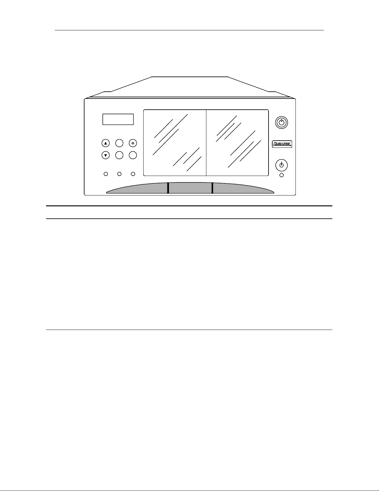
2.5.3 Front Panel Components
The entire front panel is actually a door that hinges down for servicing tape drives. A
key-operated lock secures the door. Figure 2-1 shows the various features of the front
panel. When the front door is opened, an interlock switch prevents further robotic
movement until the door is closed.
2-4 Product Description 501490 Rev. Q
 Loading...