

Qualstar Q48, Q24 Installation And Operation Manual

Q24™ and Q48™ Tape Library
Installation and Operations Manual
Document No. 511011 Rev 03

Q24/Q48 Tape Library Installation and Operations Manual
Date
Issue
Revision
Author
Description of changes
2014-04-04
Initial release
01
Dennis Klein
2015-06-12
02
Michael Smith
Add Q48 model
2015-09-30
03
David Mana
Additional Q48 updates
Copyright
© Copyright 2014-2015, QUALSTAR. All rights reserved. This document and the information
contained herein are the property of QUALSTAR. No part of this document may be reproduced,
transmitted, transcribed, stored in a retrieval system, or translated into any language or computer
language in any form or by any means, electronic, mechanical, magnetic, optical, manual, or otherwise,
without the express written permission of QUALSTAR.
Trademark Notices
QUALSTAR makes no representation or guarantees with respect to the contents of this document and
specifically disclaims any implied warranties of merchantability or fitness for any particular purpose.
Further, QUALSTAR reserves the right to revise this publication without obligation of QUALSTAR to
notify any person or organization of such revision or changes.
Q24™ and Q48™ are Trademarks of Qualstar Corporation
Revision History
© Copyright QUALSTAR 2015 ii

Q24/Q48 Tape Library Installation and Operations Manual
Contacting Qualstar
Sales
Qualstar Corporation
31248 Oak Crest Drive, Suite 120
Westlake Village, CA 93061, U.S.A.
Tel: 805-583-7744
Fax: 805-583-7749
Technical Support
Available 7:00am – 4:00pm PST
Tel: 877-444-1744 (USA)
805-583-7744 (International)
Help Desk support after hours:
Tel: 805-526-7480
For non-urgent questions, please use the form on our website at:
http://www.qualstar.com/service-requests/
Product warranty caution
The Q24/Q48 Tape Library contains no user-serviceable components. Only an authorized service
center should carry out any servicing or repairs. The warranty for the tape library shall not apply to
failures of any unit when:
• Any of the tape library components is repaired or modified by anyone other than Qualstar’s
personnel or approved agent. Note: Certain components of the Q24/Q48 Tape Library, are
identified in this manual as ‘field replaceable’. These include the power supply, tape drives,
library controller and magazines. User replacement of such complete components with
corresponding parts supplied by Qualstar does not affect warranty, provided the user strictly
adheres to the instructions herein.
• The tape library is physically abused, or used in a manner that is inconsistent with the
operating instructions or product specification defined by Qualstar.
• The tape library fails because of accident, misuse, abuse, neglect, mishandling, misapplication,
alteration, faulty installation, modification, or service by anyone other than the factory service
center or its approved agent.
• The tape library is repaired by anyone, including an approved agent, in a manner that is
contrary to the maintenance or installation instructions supplied by Qualstar.
• The manufacturer's serial number tag is removed.
• The tape library is damaged because of improper packaging on return.
In case of unauthorized repairs or modifications, your warranty becomes immediately void.
© Copyright QUALSTAR 2015 iii
Q24/Q48 Tape Library Installation and Operations Manual
DANGER
High voltage - Risk of electric shock
Refer servicing to qualified service personnel.
WARNING
Weight of Q24/Q48 Tape Library - Risk of personal
Extend only one rack component at a time.
CAUTION
Static sensitive - Risk of damage to devices
precautions to prevent damage.
NOTE
Ventilation – Place the product so that its location does not
liquids are not spilled into the product’s enclosure.
General warnings
Do not remove cover (or back). No user-serviceable parts are inside.
injury
Before lifting a library:
Observe local health and safety requirements and guidelines for
manual material handling.
Remove all tape cartridges to reduce the weight.
Obtain adequate assistance to lift and stabilize the library during
installation or removal.
Risk of damage to devices
When placing a library into or removing the library from a rack:
Extend the rack’s leveling jacks to the floor.
Ensure that the full weight of the rack rests on the leveling jacks.
Install stabilizing feet on the rack.
A discharge of static electricity damages static-sensitive devices
Proper packaging and grounding techniques are necessary
Heat – Place the product so that its location is away from heat
Power sources – Connect the product to a power source only
Power cord protection – Place the AC line cord so that it is not
Object and liquid entry – Insure that objects do not fall and
or micro circuitry.
interfere with proper ventilation.
sources.
of the type directed in the operating instructions or as marked
on the product.
possible to be walked on or pinched by items placed upon or
against it.
© Copyright QUALSTAR 2015 iv

Q24/Q48 Tape Library Installation and Operations Manual
Contents
1 Product Overview and Features .................................................................... 1
1.1 Hardware Configuration ............................................................................................ 2
1.1.1 Q24 Tape Library ......................................................................................... 2
1.1.2 Q48 Tape Library ......................................................................................... 2
1.2 Front Panel ................................................................................................................ 3
1.2.1 Q24 Tape Library Front panel ...................................................................... 3
1.2.2 Q48 Tape Library Front panel ...................................................................... 3
1.3 Rear Panel .................................................................................................................. 5
1.3.1 Q24 Power supply ........................................................................................ 6
1.3.2 Q48 Power supply ........................................................................................ 6
1.3.3 Tape drives ................................................................................................... 6
1.3.4 Library controller .......................................................................................... 7
2 Installation ..................................................................................................... 8
2.1 Location Requirements ............................................................................................. 8
2.2 Serial Attached SCSI (SAS) Requirements .................................................................. 8
2.3 Fibre Channel Requirements ..................................................................................... 9
2.4 Installation Precautions ........................................................................................... 11
2.5 Unpacking the library .............................................................................................. 12
2.6 Identifying the product components ...................................................................... 12
2.7 Removing the shipping lock..................................................................................... 13
2.8 Rack mounting the library ....................................................................................... 14
2.9 Installing a tape drive .............................................................................................. 16
2.10 Installing the library controller ................................................................................ 17
2.11 Installing a power supply ......................................................................................... 17
2.12 Connecting the cables ............................................................................................. 18
2.12.1 Connecting the power cord ......................................................................... 18
2.12.2 Connecting a Fibre Channel cable .............................................................. 19
2.12.3 Connecting a SAS cable ............................................................................. 19
2.12.4 Connecting an Ethernet cable and a USB device ....................................... 20
2.13 Verifying the host .................................................................................................... 20
2.14 Powering the library up or down............................................................................. 20
2.15 Tape cartridges ........................................................................................................ 20
2.15.1 Tape cartridge type ..................................................................................... 20
2.15.2 Using and maintaining tape cartridges ....................................................... 21
2.15.3 Labeling tape cartridges.............................................................................. 22
2.15.4 Write-protecting tape cartridges ................................................................. 23
2.16 Magazines ................................................................................................................ 23
2.16.1 Slot usage .................................................................................................... 24
3 Operating Procedures .................................................................................. 25
3.1 Operator control panel (OCP).................................................................................. 25
3.1.1 Operating Modes ........................................................................................ 25
3.1.2 OCP Rules .................................................................................................. 25
3.1.3 Power-Up Display ...................................................................................... 26
© Copyright QUALSTAR 2015 v

Q24/Q48 Tape Library Installation and Operations Manual
3.1.4 Note about the LED’s ................................................................................. 26
3.1.5 Input Modes ................................................................................................ 26
3.1.6 Power-Down ............................................................................................... 27
3.1.7 Menu flow charts (OCP)............................................................................. 28
3.2 Remote management unit (RMU) ........................................................................... 35
3.2.1 Overview .................................................................................................... 35
3.2.2 Operations through the RMU ..................................................................... 35
3.2.3 Login........................................................................................................... 36
3.2.4 RMU Screen Layout ................................................................................... 37
3.2.5 Identity ........................................................................................................ 38
3.2.6 Status .......................................................................................................... 42
3.2.7 Configuration .............................................................................................. 45
3.2.8 Operations ................................................................................................... 55
3.2.9 Service ........................................................................................................ 56
3.3 Partitioning the library ............................................................................................ 61
3.3.1 Q24 Single partition configuration .......................................................... 61
3.3.2 Q24 Dual partition configuration ............................................................ 61
3.3.3 Q48 Single partition configuration .......................................................... 61
3.3.4 Q48 Dual partition configuration ............................................................ 62
3.3.5 Q48 Three partition configuration .......................................................... 62
3.3.6 Q48 Four partition configuration ............................................................ 62
3.4 Default settings ....................................................................................................... 64
4 Troubleshooting ........................................................................................... 65
4.1 Installation problems ............................................................................................... 65
4.1.1 Cabling ....................................................................................................... 65
4.1.2 Compatibility .............................................................................................. 65
4.1.3 Backup application installation .................................................................. 65
4.1.4 Device driver installation............................................................................ 65
4.2 Troubleshooting ...................................................................................................... 66
4.3 Removing tape cartridges from the library ............................................................. 69
4.4 Emergency release .................................................................................................. 70
4.5 Upgrade the library firmware .................................................................................. 71
4.6 General diagnostic ................................................................................................... 71
4.6.1 System test .................................................................................................. 71
4.6.2 Slot-to-Slot test ........................................................................................... 71
4.6.3 Library verify test ....................................................................................... 71
4.7 Error codes .............................................................................................................. 72
4.7.1 Error messaging .......................................................................................... 72
4.7.2 Error Message format ................................................................................. 73
4.7.3 OCP error reporting .................................................................................... 73
4.7.4 RMU error reporting ................................................................................... 73
4.7.5 Main error codes ......................................................................................... 74
4.7.6 Sub error codes related to the media changer ............................................. 84
4.7.7 Sub error codes related to the library .......................................................... 86
5 Servicing ....................................................................................................... 87
5.1 Tools that may be needed ....................................................................................... 87
5.2 Electrostatic discharge ............................................................................................ 87
© Copyright QUALSTAR 2015 vi

Q24/Q48 Tape Library Installation and Operations Manual
5.3 Removing a tape drive ............................................................................................. 88
5.4 Replacing a tape drive ............................................................................................. 88
5.5 Removing the library controller .............................................................................. 89
5.6 Replacing the library controller ............................................................................... 89
5.7 Removing the power supply .................................................................................... 90
5.8 Replacing the power supply .................................................................................... 90
5.9 Servicing a magazine ............................................................................................... 90
5.10 Removing the base chassis ...................................................................................... 91
5.10.1 Preparing to remove the base chassis ......................................................... 91
5.10.2 Removing the base chassis from the rack ................................................... 91
5.11 Replacing the base chassis ...................................................................................... 92
6 Packaging the unit for transportation ......................................................... 93
7 Technical specifications ............................................................................... 96
7.1 Hardware specifications .......................................................................................... 96
7.2 Operating environment ........................................................................................... 96
7.3 Maximum storage capacity and data transfer rate ................................................. 97
8 Agency certifications .................................................................................... 98
8.1 Recycling and disposal ............................................................................................. 98
8.2 Device standards ..................................................................................................... 99
8.3 CE mark .................................................................................................................... 99
8.4 ETL mark .................................................................................................................. 99
8.5 GS mark ................................................................................................................. 100
8.6 FCC (United States) ................................................................................................ 100
8.7 Canadian verification ............................................................................................. 100
9 Glossary ...................................................................................................... 101
10 Index ........................................................................................................... 102
© Copyright QUALSTAR 2015 vii

Q24/Q48 Tape Library Installation and Operations Manual
Figures
Figure 1 Q24 / Q48 front panel control, indicators and magazines ................................................................. 4
Figure 2 Q24/Q48 rear panel components ...................................................................................................... 5
Figure 3 Q24 Power supply .............................................................................................................................. 6
Figure 4 Q48 Power supply .............................................................................................................................. 6
Figure 5 SAS half-height tape drive ................................................................................................................. 6
Figure 6 FC half-height tape drive .................................................................................................................... 7
Figure 7 Q24 / Q48 Library controller .............................................................................................................. 7
Figure 8 Fibre Channel topology (LN Port) ....................................................................................................... 9
Figure 9 Fibre Channel topology (L Port) ....................................................................................................... 10
Figure 10 Fibre Channel topology (N Port) .................................................................................................... 10
Figure 11 Removing and Storing the Shipping Lock on a Q24 ....................................................................... 13
Figure 12 Removing and Storing the Shipping Lock on a Q48 ....................................................................... 13
Figure 12 Install the rack rails ........................................................................................................................ 14
Figure 13 Install the mounting brackets ........................................................................................................ 15
Figure 14 Secure the library to the rack ......................................................................................................... 15
Figure 15 Pullout tab for product ID .............................................................................................................. 16
Figure 16 Install a tape drive .......................................................................................................................... 16
Figure 17 Install a library controller ............................................................................................................... 17
Figure 18 Install a power supply .................................................................................................................... 18
Figure 19 Connect the FC cable ...................................................................................................................... 19
Figure 20 Proper barcode label placement .................................................................................................... 22
Figure 21 Write-protecting a tape cartridge .................................................................................................. 23
Figure 22 Main menu ..................................................................................................................................... 28
Figure 23 Information menu (1 of 2) .............................................................................................................. 29
Figure 24 Information menu (2 of 2) .............................................................................................................. 30
Figure 25 Commands menu ........................................................................................................................... 31
Figure 26 Configuration menu ....................................................................................................................... 32
Figure 27 Service menu (1 of 2) ..................................................................................................................... 33
Figure 28 Service menu (2 of 2) ..................................................................................................................... 34
Figure 29 RMU Login ...................................................................................................................................... 36
Figure 30 RMU Menu System ........................................................................................................................ 37
Figure 31 System Status summary .................................................................................................................. 37
Figure 32 Library identity ............................................................................................................................... 38
Figure 33 Drive identity .................................................................................................................................. 40
Figure 34 Network identity ............................................................................................................................ 41
Figure 35 Library status .................................................................................................................................. 42
Figure 36 Drive status .................................................................................................................................... 43
Figure 37 Tape cartridge inventory (summary) ............................................................................................. 44
Figure 38 Tape cartridge inventory (detail) ................................................................................................... 44
Figure 39 System Configuration ..................................................................................................................... 45
Figure 40 Logical Libraries .............................................................................................................................. 46
Figure 41 License key ..................................................................................................................................... 47
Figure 42 Drive configuration......................................................................................................................... 47
Figure 43 Network configuration ................................................................................................................... 48
Figure 44 SNMP configuration ....................................................................................................................... 50
© Copyright QUALSTAR 2015 viii

Q24/Q48 Tape Library Installation and Operations Manual
Figure 45 User account settings ..................................................................................................................... 51
Figure 46 Date/time settings.......................................................................................................................... 52
Figure 47 Error Log mode ............................................................................................................................... 53
Figure 48 Event parameters for Email Notification ........................................................................................ 53
Figure 49 Factory defaults .............................................................................................................................. 54
Figure 50 Move media ................................................................................................................................... 55
Figure 51 Media Inventory ............................................................................................................................. 55
Figure 52 Release magazines ......................................................................................................................... 56
Figure 53 Library diagnostics .......................................................................................................................... 56
Figure 54 Drive diagnostics ............................................................................................................................ 57
Figure 55 Firmware updates .......................................................................................................................... 57
Figure 56 Reboot the library .......................................................................................................................... 58
Figure 57 Library logs ..................................................................................................................................... 58
Figure 58 Clean a tape drive ........................................................................................................................... 59
Figure 59 Cartridge Memory .......................................................................................................................... 60
Figure 60 Removing a stuck tape ................................................................................................................... 69
Figure 61 Rear panel (access holes) ............................................................................................................... 70
Figure 62 Front panel (magazine removal) .................................................................................................... 70
Figure 63 OCP Error display ............................................................................................................................ 73
Figure 64 RMU Error display .......................................................................................................................... 73
Figure 65 Remove a tape drive ...................................................................................................................... 88
Figure 66 Remove the library controller ........................................................................................................ 89
Figure 67 Remove the power supply ............................................................................................................. 90
Figure 68 Re-installing Shipping Lock ............................................................................................................. 92
Figure 69 Product ID label .............................................................................................................................. 93
Figure 70 Packaging the Q24 library .............................................................................................................. 94
Figure 71 Packaging the Q48 library .............................................................................................................. 94
Figure 72 WEEE symbol .................................................................................................................................. 98
Figure 73 Device standards ............................................................................................................................ 99
Tables
Table 1 Location requirements ........................................................................................................................ 8
Table 2 Tape cartridge type ........................................................................................................................... 20
Table 3 Backward compatibility (tape cartridges) ......................................................................................... 21
Table 4 Legend of status icons (RMU) ............................................................................................................ 38
Table 5 Default settings.................................................................................................................................. 64
Table 6 Troubleshooting ................................................................................................................................ 68
Table 7 Error codes ........................................................................................................................................ 83
Table 8 Packaging the library ......................................................................................................................... 95
Table 9 Hardware specifications ................................................................................................................... 96
Table 10 Operating environment ................................................................................................................... 96
Table 11 Q24 Maximum storage capacity and data transfer rate ................................................................. 97
Table 12 Q48 Maximum storage capacity and data transfer rate ................................................................. 97
© Copyright QUALSTAR 2015 ix

Q24/Q48 Tape Library Installation and Operations Manual
1 Product Overview and Features
This manual provides information about installing, operating, troubleshooting and servicing a Qualstar
Q24 or Q48 Tape Library. It is intended for system administrators and general users who need
physical and functional knowledge of the Q24 or Q48 Tape Library.
The two libraries are similar, physically and functionally. The primary difference is the height of the
Q48. The Q48 is twice the height of the Q24. The Q48’s added height increases the tape cartridge
capacity to 48 slots, and the number of tape drives to a maximum of four.
This document uses the reference Q24/Q48 to refer to either the Q24 or the Q48 Tape Library.
The Q24/Q48 Tape Library provides a compact, high capacity, low-cost solution for simple,
unattended data backup. It is compatible with most host operating systems and environments
provided the host is equipped with the appropriate interface card. However, the library requires either
direct support from the operating system or a compatible backup application to take full advantage of
its many features.
Major characteristics of the Q24/Q48 Library include:
• Platform – support for either one or two half-height LTO5 or LTO6 tape drives in a Q24 Tape
Library, and one to four in a Q48 Tape Library.
• Connectivity – Fibre Channel (FC) and/or Serial Attached SCSI (SAS) depending upon
installed tape drives
• Expandability – additional half-height tape drives may be field-installed in a library that has
unused drive slot locations.
• Technology upgrade – tape drive technologies can be upgraded in the field (i.e. LTO5 to LTO6)
• Service friendly design – easy access to magazines, tape drives, library controller and power
supply for field replacement
• Maximum up time – through advanced error handling and recovery capability
The Q24/48 Library includes the following features:
• USB interface to enable serviceability features (library and drive firmware upgrades) and/or
customized features (storage on demand) implementation
• The library can be operated via the front operator control panel (OCP), over the network or the
Internet via the integral remote management unit (RMU), or via the storage interface connection
from the host application
• Supports industry standard management protocols such as SNMP (SMI-S future development)
• The Q24 has one mail slot for import/export of cartridges during library operation while the Q48
has three mail slots
• Media changer with barcode reader
• Rack-mounted or standalone operation
© Copyright QUALSTAR 2015 1

Q24/Q48 Tape Library Installation and Operations Manual
Height:
2U
Tape drives:
1 or 2 half-height drives
Number of magazines:
2 (12 slots each)
Power supply:
1
Number of mail slots:
1
Library controller:
1
Number of tape slots:
24 (less mail slots)
Height:
4U
Tape drives:
1 to 4 half-height drives
Number of magazines:
4 (12 slots each)
Power supply:
1
Number of mail slots:
3
Library controller:
1
Number of tape slots:
48 (less mail slots)
1.1 Hardware Configuration
1.1.1 Q24 Tape Library
1.1.2 Q48 Tape Library
© Copyright QUALSTAR 2015 2
Q24/Q48 Tape Library Installation and Operations Manual
9
10
11
12
5
6
7
8
4
3
2
1
1
13
6 7 8
9
10
11
12
4 3 2 1 1
13
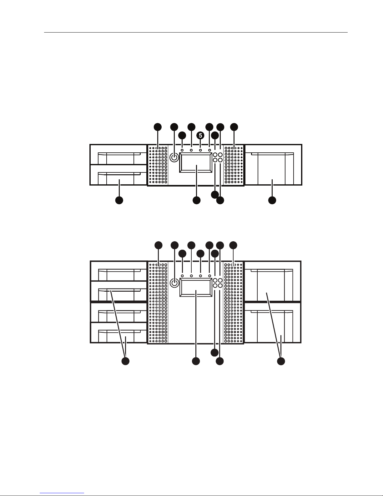
1.2 Front Panel
The front panel of the Q24 and Q48 Tape Library is used to access the power button, operator control
panel (OCP), left and right magazines, LED’s, and the mail slot.
1.2.1 Q24 Tape Library Front panel
1.2.2 Q48 Tape Library Front panel
© Copyright QUALSTAR 2015 3

Q24/Q48 Tape Library Installation and Operations Manual
Ref.
Description
1
Air vents
2
Power button: Pressing the button will initiate a controlled power down of the library (soft power down)
LED <READY> (green): is illuminated during power on; blinking during tape or library media changer
activity.
LED <CLEAN> (amber): is illuminated when the tape drive has determined that a cleaning tape should be
used. Cleaning is only necessary when the library directs to do so. Additional cleaning is not necessary.
LED <ATTENTION> (amber): is illuminated when the library has detected a condition that requires
attention by the operator.
LED <ERROR> (amber): is illuminated when an unrecoverable tape drive or library error occurs. A
corresponding error message is shown on the LCD screen.
7
<UP> button [◄]: is used to navigate backward through menu items.
8
<CANCEL> button []: is used to cancel a user action and return to the last menu item.
9
<DOWN> button [►]: is used to navigate forward through menu items.
10
<ENTER> button [↵]: is used to enter to a sub menu or execute an action.
Operator control panel (OCP) consisting of a 128 x 64 pixel screen. The OCP displays actions and status
information, menu items or error messages relevant to the operational mode.
12
Right magazine(s)
13
3
4
5
6
11
Left magazine with mail slot(s)
Figure 1 Q24 / Q48 front panel control, indicators and magazines
opyright QUALSTAR 2015 4
© C
Q24/Q48 Tape Library Installation and Operations Manual
Ref.
Description
Ref.
Description
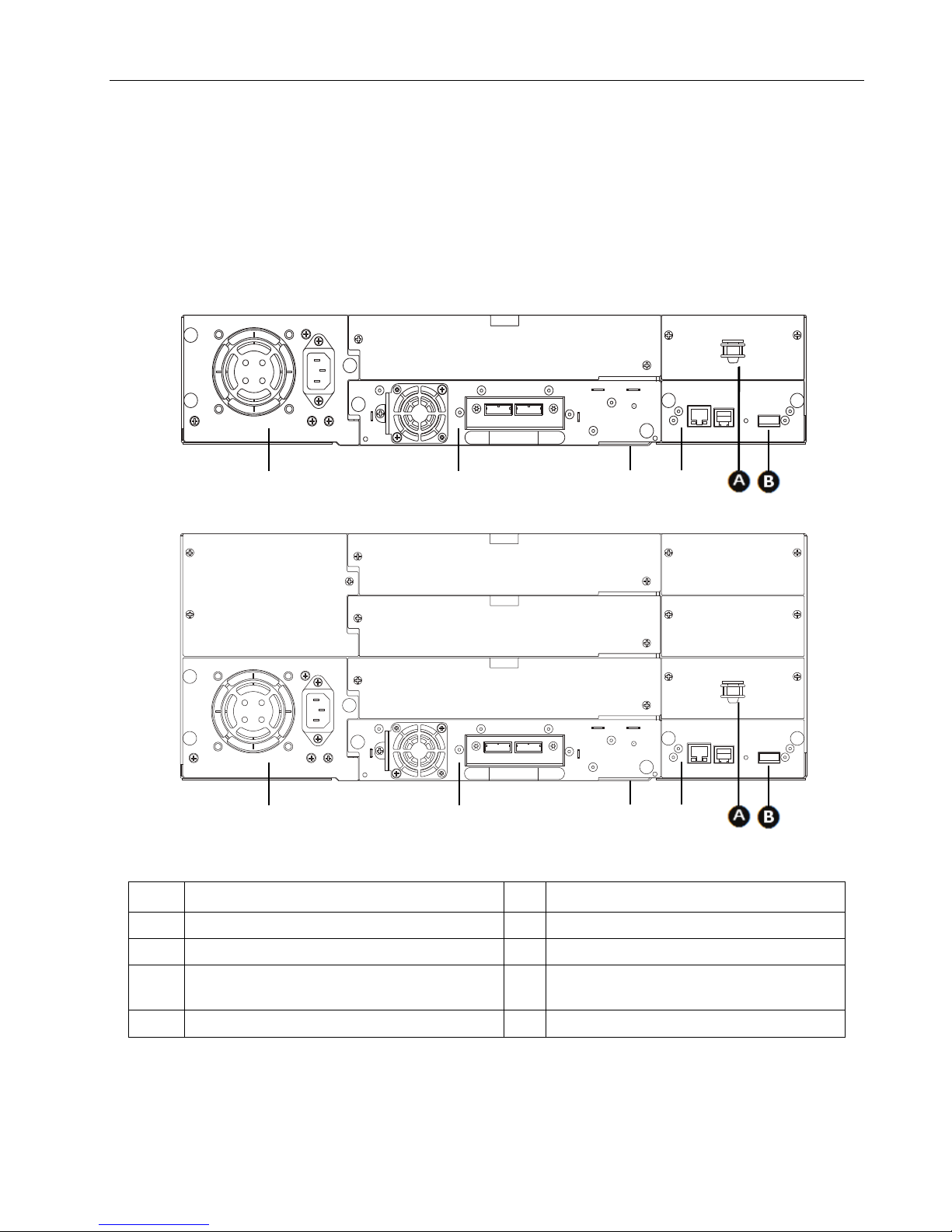
1
Power supply (lower left)
A
Storage location for shipping lock.
2
Tape drive(s)
B
USB port (firmware upgrades, key storage)
3
Pull-out tab containing the product information
(Serial Number/Model/Customer)
4
Library controller
Q24
Q48
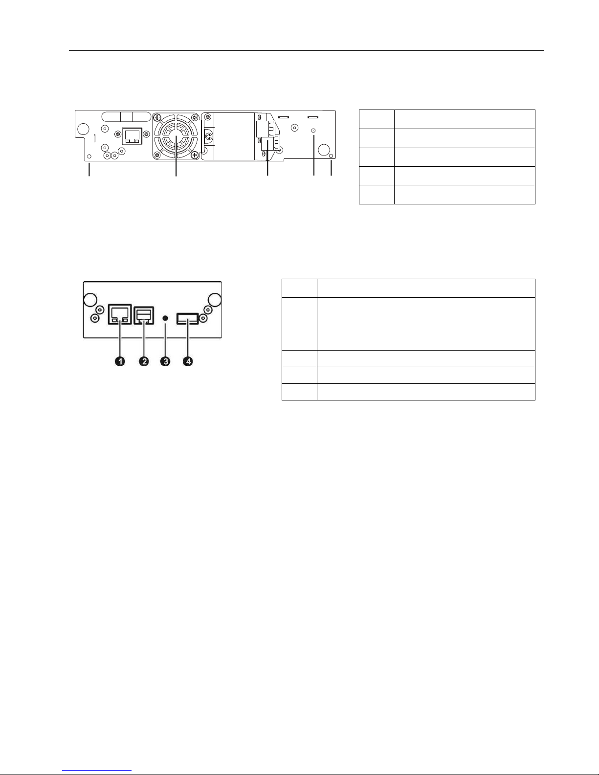
1.3 Rear Panel
The rear panel of the Q24/Q48 Tape Library provides access to the drive interface connectors (either
SAS or Fibre Channel), the power connector, Ethernet, serial and USB ports and the magazine release
holes.
The power supply is on the left side, tape drives are in the middle and the library controller is on the
right side of the library.
Figure 2 Q24/Q48 rear panel components
© Copyright QUALSTAR 2015 5
Q24/Q48 Tape Library Installation and Operations Manual
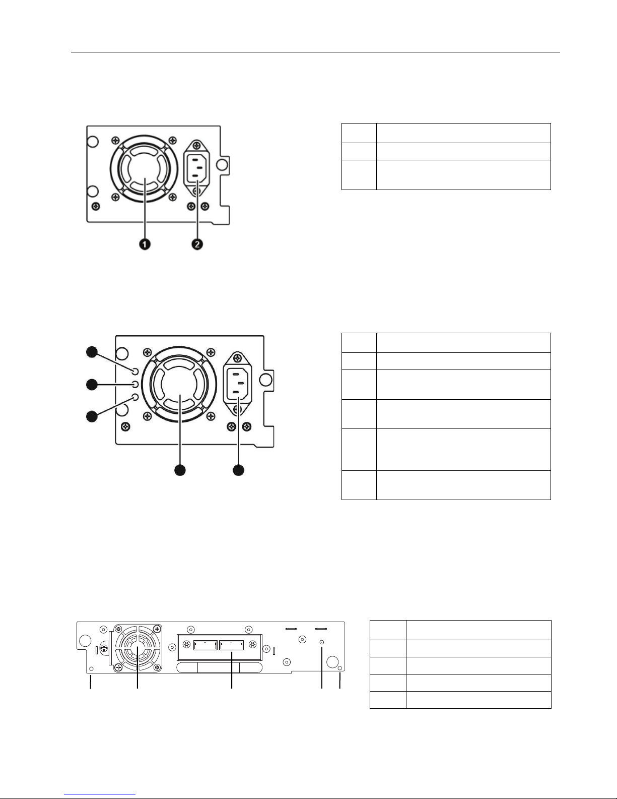
Ref.
Description
1
Fan vent
2
Power connector
110/220 V AC power connection.
Ref.
Description
1
Fan vent
2
Power connector
110/220 V AC power connection.
3
LED (blue) is illuminated when AC power
is connected.
4
LED (amber) is illuminate when a fan
or defective.
5
LED (green) is illuminated when power is
good.
Ref.
Description
1
Magazine release holes
2
Fan vent
3
SAS connectors
4
Tape drive LED
1 2 5 4 3
1.3.1 Q24 Power supply
Figure 3 Q24 Power supply
1.3.2 Q48 Power supply
failure occurs. The fan is running to slow
Figure 4 Q48 Power supply
1.3.3 Tape drives
SAS connectors for both LTO Generations
Figure 5 SAS half-height tape drive
© Copyright QUALSTAR 2015 6
Q24/Q48 Tape Library Installation and Operations Manual
Ref.
Description
1
Magazine release holes
2
Fan vent
3
FC connectors
4
Tape drive LED
Ref.
Description
1
Ethernet port (RMU connection). Left LED (amber) is
or in use
2
Serial port (Engineering Diagnostics)
3
Controller LED blinking ok; if not, failure
4
USB port (Firmware upgrades, key storage)
A
B
FC connectors for both LTO Generations
Figure 6 FC half-height tape drive
1.3.4 Library controller
illuminated when a connection is in place. Right LED
(green) is illuminated when the connection is ready
Figure 7 Q24 / Q48 Library controller
© Copyright QUALSTAR 2015 7

Q24/Q48 Tape Library Installation and Operations Manual
Criteria
Definition
Rack requirements
Standard 19-inch rack with vertical space of 2U available for the Q24 or vertical
space of 4U available for the Q48.
Room temperature
10-35° C (50-95° F)
Power source
AC power voltage: 100-127 VAC; 200-240 VAC
accessible at all times.
Air quality
Place the library in an area with minimal sources of particulate contamination.
Excessive dust and debris can damage tapes and tape drives.
Humidity
20-80 percent relative humidity non-condensing
Clearance
Back: Minimum of 15.4 cm (6 inches)
Sides: Minimum of 5.08 cm (2 inches)
2 Installation
This section provides instructions for installing the Q24/Q48 Tape Library.
2.1 Location Requirements
Line frequency: 50-60 Hz
Place the library near to an AC outlet.
The AC power cord is the library’s main AC disconnect device and must be easily
Avoid areas near frequently used doors and walkways, stacks of supplies that
collect dust, printers, and smoke-filled rooms.
Front: Minimum of 30.8 cm (12 inches) – for mail slot
Minimum of 60 cm to remove magazines (24 inches)
Table 1 Location requirements
For further information, see Section 7, Technical specifications
2.2 Serial Attached SCSI (SAS) Requirements
Serial Attached SCSI (SAS) is a computer bus technology mainly used to transfer data to and from
storage devices, including disk drives and tape drives. SAS is designed to transfer data at up to
6 gigabits per second.
SAS uses serial connections, with a direct connection between the host server and each of the storage
devices. This eliminates the need to configure SCSI buses and assign SCSI IDs, as was required for
parallel SCSI devices.
Most SAS host bus adapters (HBA) ports have four SAS channels. A tape drive uses one channel, so
each HBA port can support up to four tape drives via a fan-out cable. You can use a cable with one
connector on each end, but only one channel will be used.
© Copyright QUALSTAR 2015 8
Q24/Q48 Tape Library Installation and Operations Manual
NOTE
The library has a mini-SAS connector on each SAS tape drive.
Mini-SAS connectors are keyed.
A SAS tape drive is identified by a unique identifier called a World Wide Name (WWN) or World Wide
Identifier (WWID). The library assigns the WWID to the drive bay. When a tape drive is replaced, the
WWID is re-assigned to the new tape drive.
The operating system tracks the WWID for the tape drive on each HBA channel. Each of the drive
connectors on the fan-out cable is associated with an HBA channel. Once a tape drive has been plugged
in, it should remain on the same channel to retain the association between the HBA channel and
WWID.
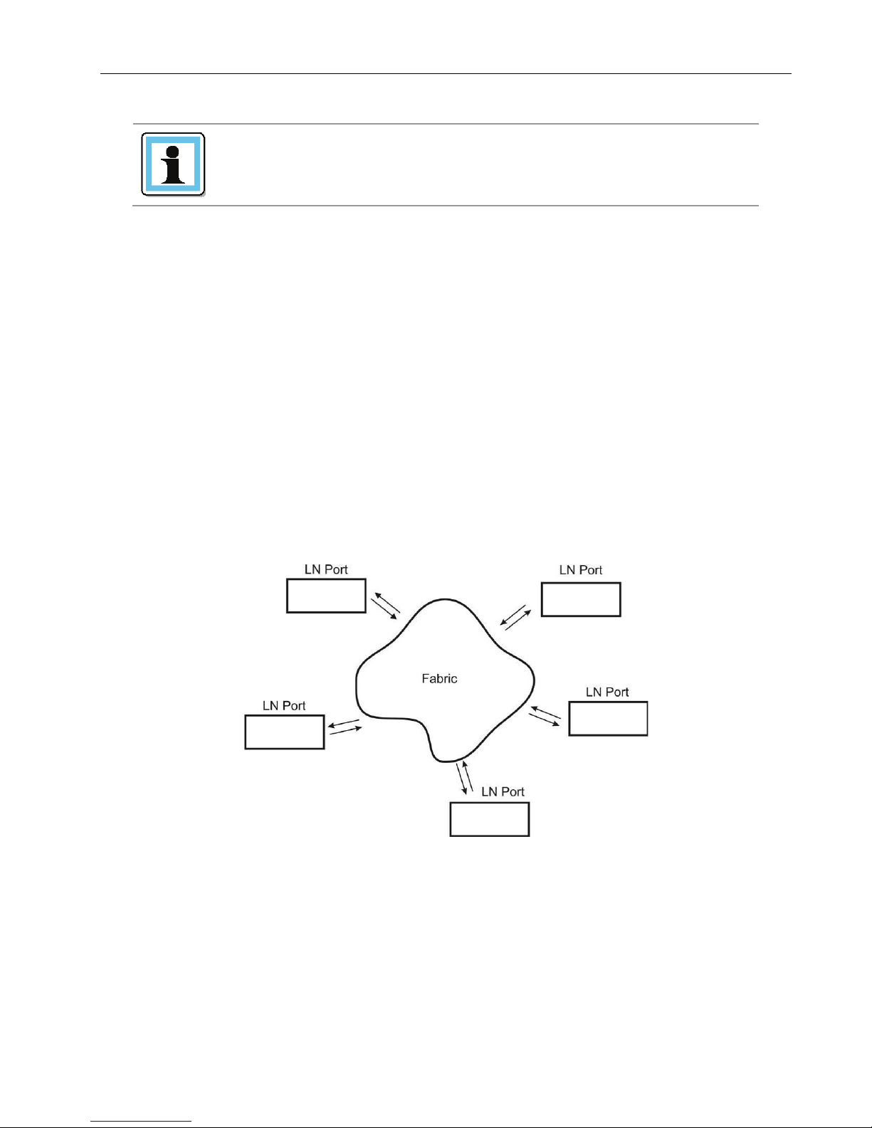
2.3 Fibre Channel Requirements
Fibre Channel (FC) allows an active intelligent interconnection scheme, called a Fabric , to connect
devices. Everything between the ports on FC is called the Fabric. The Fabric is most often a switch or
series of switches that takes the responsibility for routing.
The library allows the selection of the following Fibre Channel port behaviors:
• LN Port (default setting) – an automatic configuration that tries arbitrated loop first, then switched
Fabric.
Figure 8 Fibre Channel topology (LN Port)
© Copyright QUALSTAR 2015 9
Q24/Q48 Tape Library Installation and Operations Manual
NOTE
Use an appropriate HBA for your tape drive due to performance
library.
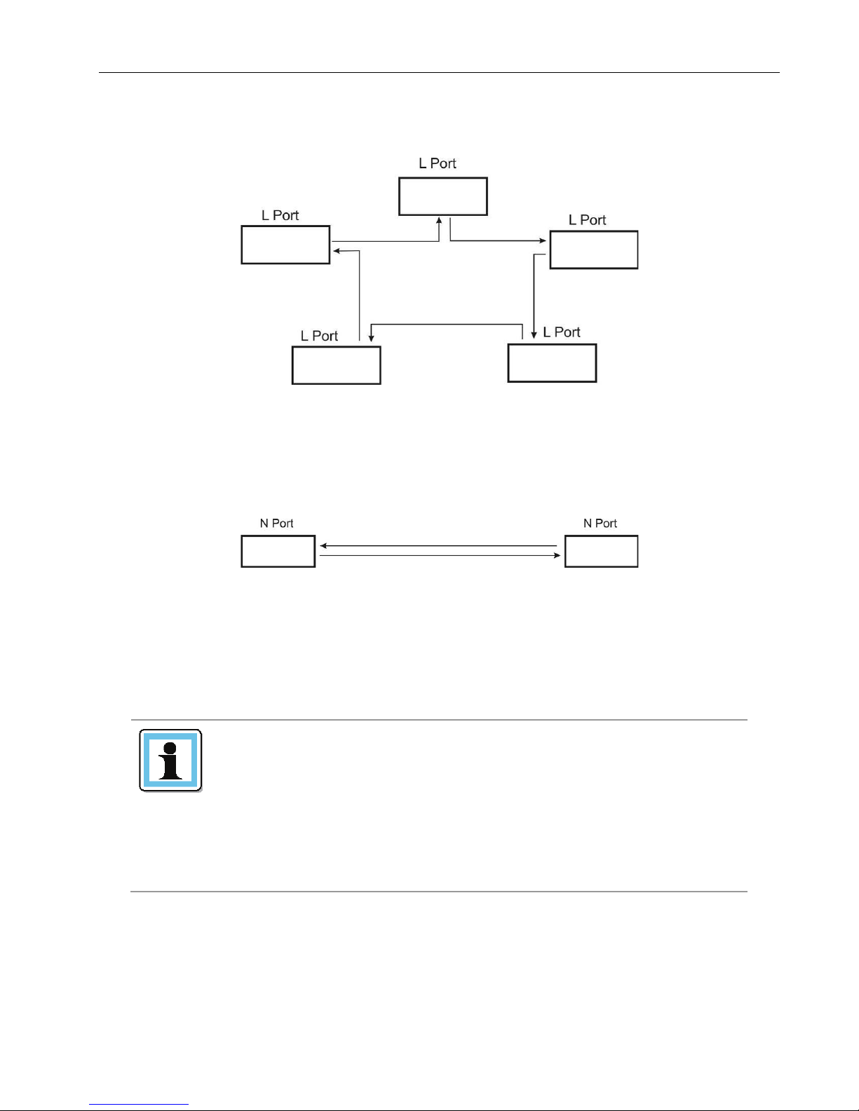
• L Port – arbitrated loop
Figure 9 Fibre Channel topology (L Port)
• N Port – point to point protocol in a switched Fabric topology
Figure 10 Fibre Channel topology (N Port)
The Fibre Channel tape drive can be connected directly to the server with a host bus adapter (HBA) or
through a storage area network (SAN).
In a SAN installation, all switches between the host and the
considerations. A lower throughput HBA might result in
performance degradation when backing up highly compressible
data to a higher throughput tape drive.
library must be of the appropriate type. A lower throughput
switch in the path may result in performance degradation.
Configure zoning so only the backup servers may access the
© Copyright QUALSTAR 2015 10
Q24/Q48 Tape Library Installation and Operations Manual
CAUTION
Static sensitive - Risk of damage to devices
See Section 5.2, Electrostatic discharge
WARNING
Weight of Q24/Q48 Tape Library - Risk of personal injury
Extend only one rack component at a time.
NOTE
Do not expose the library to moisture.
2.4 Installation Precautions
A discharge of static electricity damages static-sensitive devices
or micro circuitry.
Proper packaging and grounding techniques are necessary
precautions to prevent damage.
Before lifting a library:
Observe local health and safety requirements and guidelines for
manual material handling.
Remove all tape cartridges to reduce the weight.
Obtain adequate assistance to lift and stabilize the library during
installation or removal.
Risk of damage to devices
When placing a library into or removing the library from a rack:
Extend the rack’s leveling jacks to the floor.
Ensure that the full weight of the rack rests on the leveling jacks.
Install stabilizing feet on the rack.
Use the library on a firm level surface free from vibration.
Do not place anything on top of the library.
© Copyright QUALSTAR 2015 11
Q24/Q48 Tape Library Installation and Operations Manual
NOTE
If the temperature in the room where the library will be
it from the shipping container.
NOTE
Do not place the library on either end or sides as this may
2.5 Unpacking the library
Before unpacking the library, clear a work surface on which to place the unpacked components. If the
library will be installed in a rack, select an open rack location allowing easy access to the host server
and an easily accessible power outlet.
installed varies by 15° C (30° F) or more from the room where
the library was stored, allow the library to acclimate to the
surrounding environment for at least 12 hours before unpacking
1. Before opening and removing the tape library from the box, inspect the container for shipping
damage. If you notice any damage, report it to the shipping company immediately.
2. Open the box.
3. Carefully remove the shipping materials from the top of the library.
4. Remove the accessory package and set aside (if included).
5. Remove the two rack rails and set aside (if included).
6. Lift the library out of the carton and remove the bag from the loader. Save the packaging
materials for future use.
damage it.
2.6 Identifying the product components
Confirm that you received the following:
1. Q24/Q48 Tape Library, including power supply, 1 or more half-height tape drives (as ordered),
library controller, and two tape magazines for the Q24, or four magazines for the Q48.
2. Rack mount kit:
- 2 rack mount rails
- 1 bag of eight M6 screws for the rack mounting (9.5 mm square holes in the rack column)
- 1 bag of eight M6 screws for rack mounting (6.85 mm round holes in the rack column)
- 2 mounting brackets
- T10 Torx screws to attach the mounting brackets
- M5 screws to secure the mounting brackets to the rack
3. Power cord
4. Library documentation
Optional components, depending on the purchased configuration:
1. Cables - for instance Fibre Channel and SAS cables
© Copyright QUALSTAR 2015 12
Q24/Q48 Tape Library Installation and Operations Manual
NOTE
The shipping lock, which prevents the media changer transport
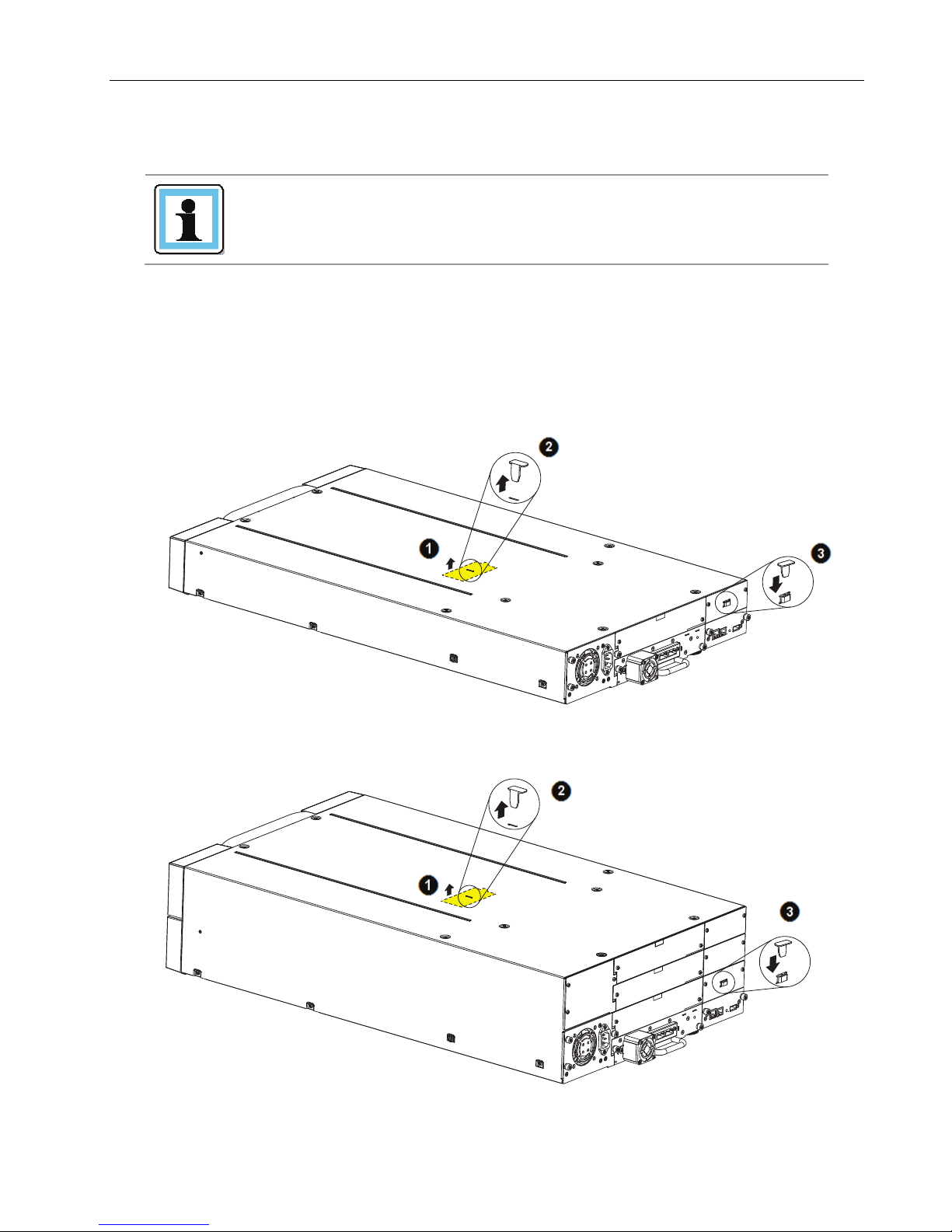
2.7 Removing the shipping lock
mechanism from moving during shipment, must be removed
before the library is powered on.
To remove and store the shipping lock:
1. Remove the yellow label that is securing the shipping lock on the top of the library.
2. Remove the shipping lock.
3. Store the shipping lock in the slot provided on the rear panel (Important: The lock is required
if the library is to be returned or transported to a new location at some future time).
4. Replace the yellow label on the top of the library.
Figure 11 Removing and Storing the Shipping Lock on a Q24
Figure 12 Removing and Storing the Shipping Lock on a Q48
© Copyright QUALSTAR 2015 13
Q24/Q48 Tape Library Installation and Operations Manual
NOTE
The rack rail components are optional accessories depending on
components are not included.
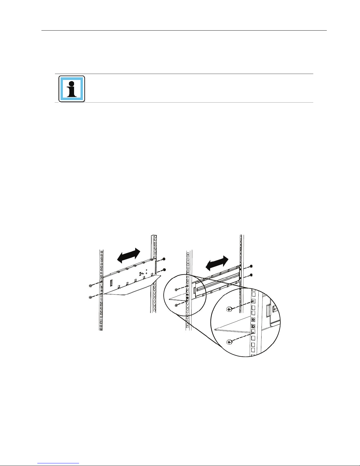
2.8 Rack mounting the library
the ordered configuration. Skip this section, when the rack rail
Required tools:
• #3 Phillips screwdriver
• T10 Torx screwdriver
Rack mounting the library:
1. Determine the location in which the library rack is to be installed.
2. Use a pencil to mark the location on each vertical rail in the rack.
3. In the rack mount kit are two sets of eight M6 screws. Determine the type of rack then choose
the appropriate type of M6 screws.
4. Secure one rail to each side of the rack in your chosen rack location with a #3 Phillips
screwdriver. Insure the rails are mounted level and at the same rack height on each side.
5. Secure both the front and back of each rack rail to the rack.
Figure 13 Install the rack rails
© Copyright QUALSTAR 2015 14
Q24/Q48 Tape Library Installation and Operations Manual
6. Install mounting brackets for the library using the Torx screws included in the rack mount kit.
Figure 14 Install the mounting brackets
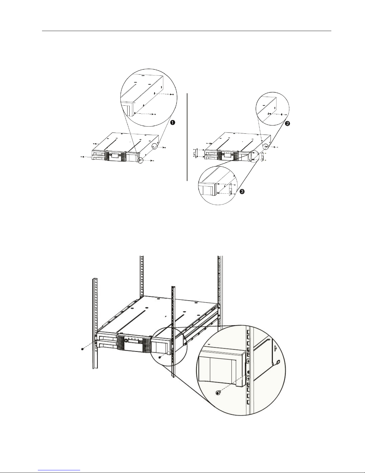
7. Slide the library onto the rack rails.
8. Secure the library to the rack using a 3# Phillips screwdriver placed through the small holes in
the mounting bracket to tighten the M5 screw(s) on each side of the library.
Figure 15 Secure the library to the rack
© Copyright QUALSTAR 2015 15
Q24/Q48 Tape Library Installation and Operations Manual
2.9 Installing a tape drive
A tape drive is installed from the rear of the library. If the library does not already have a tape drive
installed, install it now. If the library already has one tape drive installed, an additional tape drive may
be added now or after installation of the library is complete.
Required tool:
• #2 Phillips screwdriver
To install tape drives:
1. The Q24 has space for either 1 or 2 half-height tape drives. The Q48 has space for 1 to 4 half-
height tape drives. Always install the first tape drive in the bottom of the drive bay. A drive bay
cover must be installed over any upper empty drive positions.
2. If a drive cover is present, loosen the screws and remove the cover to install one half-height
tape drive.
3. When installing the bottom drive, slightly pull out the tab of the product ID label so it does not
interfere with the insertion or removal of the tape drive.
Figure 16 Pullout tab for product ID
4. Before installing the drive, inspect the connectors on it. Ensure that the connectors are intact,
free of any foreign objects, and have no cracks, or deformed or bent contacts.
5. Insert the tape drive into the drive bay, and align the connectors on the library while
supporting the drive.
Figure 17 Install a tape drive
© Copyright QUALSTAR 2015 16
Q24/Q48 Tape Library Installation and Operations Manual
6. Push the tape drive into the drive bay until the tape drive seats itself against the back of the
library. If extended, push the tab for the product ID label back into the library.
7. Tighten the blue captive screws with your fingers to secure the tape drive to the library.
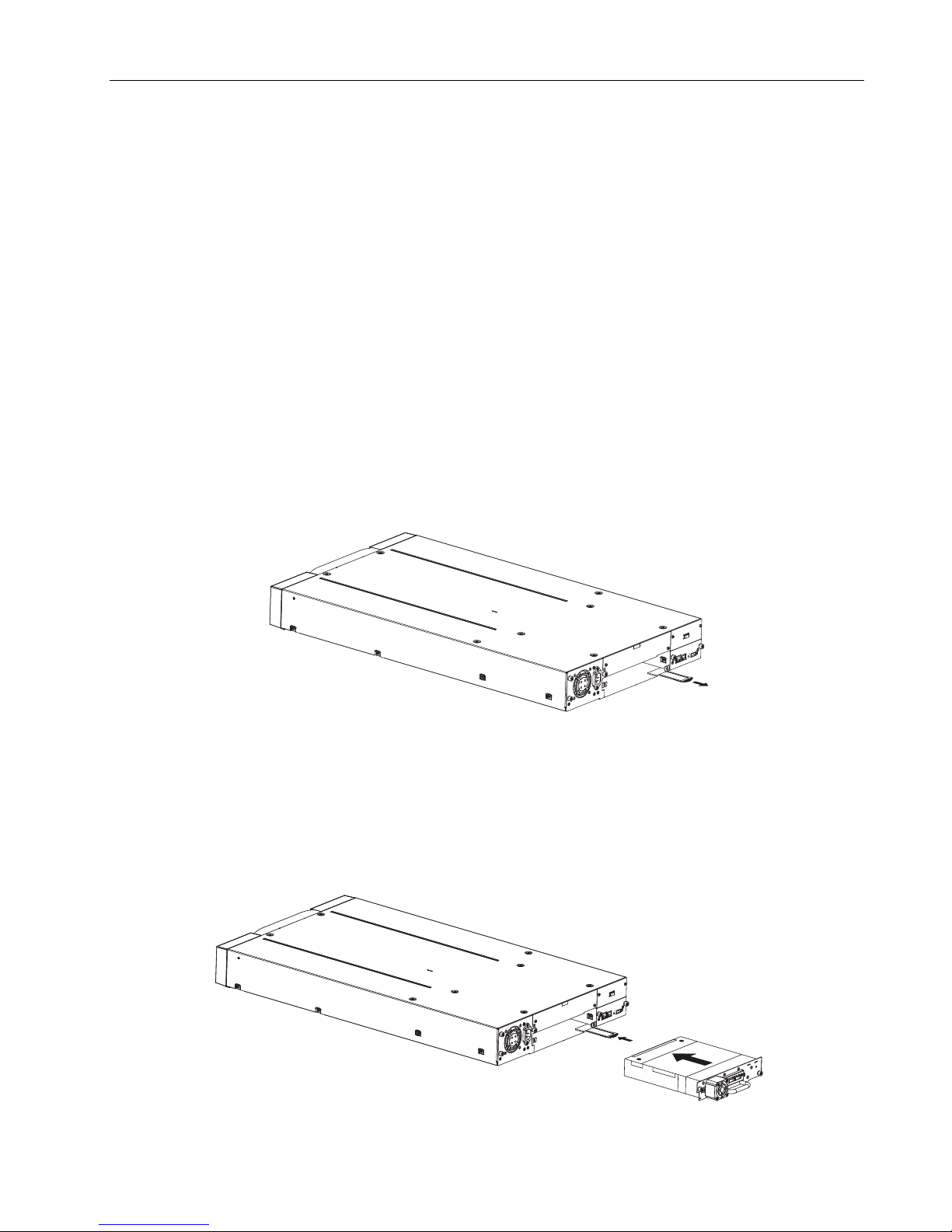
2.10 Installing the library controller
The library controller is installed from the rear of the library. If the library does not already have a
library controller installed, install it now.
Required tool:
• #2 Phillips screwdriver
To install a library controller:
1. Locate the vacant library controller bay on the lower right side of the rear panel.
2. If present, loosen the screws and remove the library controller bay cover.
3. Before installing the library controller, inspect its connectors. Ensure that the connectors are
intact, free of any foreign objects, and have no cracks or deformed or bent contacts.
4. Insert the library controller on the alignment rails and push it into the bay until it seats itself
against the back of the library.
Figure 18 Install a library controller
5. Tighten the blue captive screws with your fingers to secure the library controller.
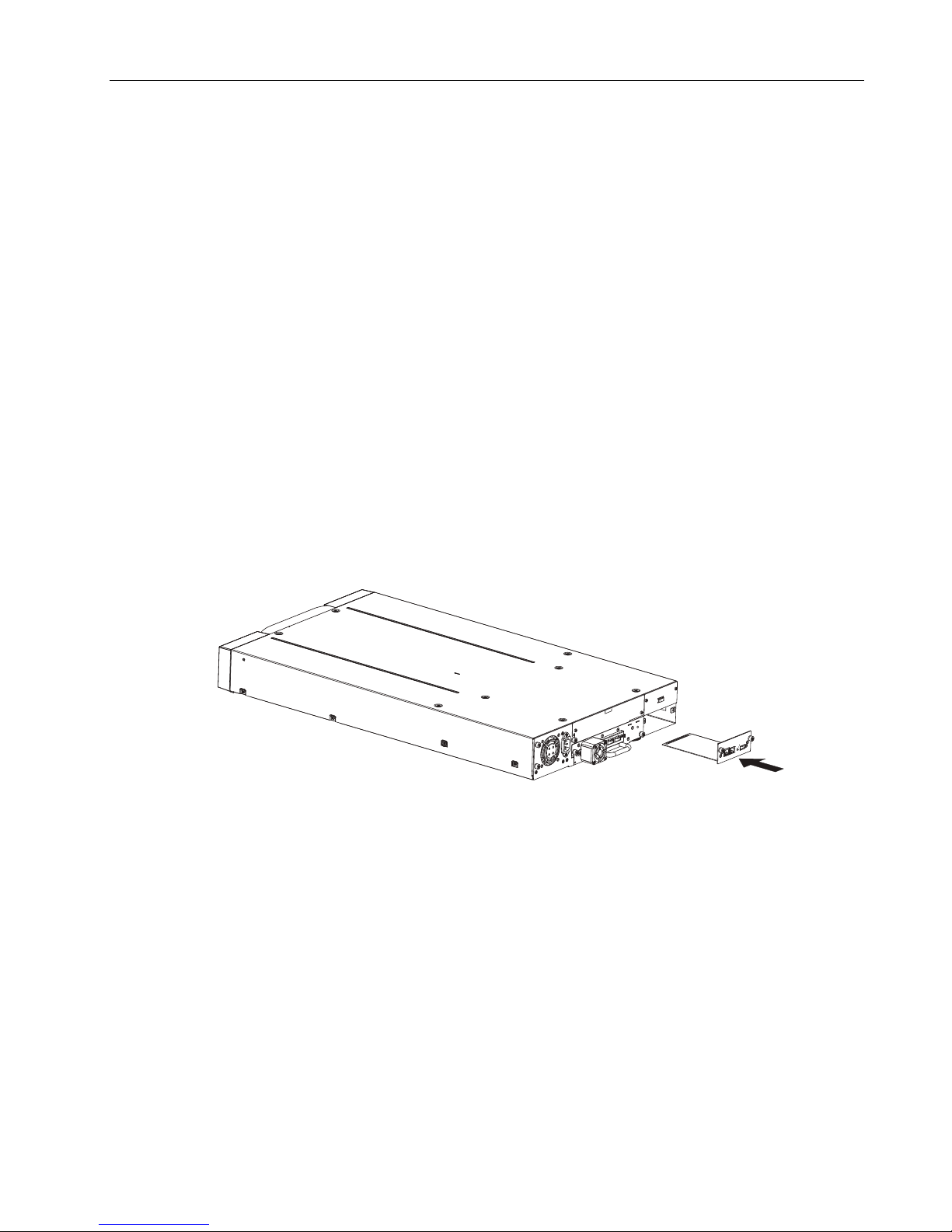
2.11 Installing a power supply
The power supply is installed from the rear of the library. If the library does not have a power supply
installed, install it in the left power supply bay now.
Required tool:
• #2 Phillips screwdriver
To install a power supply:
1. Locate the power supply bay on the lower left side of the rear panel of the library.
2. If present, loosen the screws and remove the power supply bay cover.
© Copyright QUALSTAR 2015 17
Q24/Q48 Tape Library Installation and Operations Manual
DANGER
High voltage - Risk of electric shock
manual material handling.
WARNING
Usage of non-approved power cords
non-manufacturer approved power cord is used.
3. Before installing the power supply, inspect its connectors. Ensure that the connectors are
intact, free of any foreign objects, and have no cracks or deformed or bent contacts.
Figure 19 Install a power supply
4. Insert the power supply on the alignment rails and push it into the bay until it seats itself
against the back of the library.
5. Tighten the blue captive screws with your fingers to secure the power supply to the library.
2.12 Connecting the cables
2.12.1 Connecting the power cord
Use only approved power cords.
Observe local health and safety requirements and guidelines for
- Risk of personal injury
- Risk of damage to devices
Before connecting a power cord to the library:
Ensure that the power cord meets individual country specific
safety standards.
Use a sufficient conductor current capacity (amps) to avoid
overheating the cord.
The manufacturer disclaims all liability in the event a
To connect the power cord to the library:
1. Plug the female connector of the power cord into the power connector (AC connector) on the
rear panel of the power supply. For the Q24, refer to section 1.3.1 Q24 Power supply. For the
Q48, refer to section 1.3.2 Q48 Power supply.
© Copyright QUALSTAR 2015 18
Q24/Q48 Tape Library Installation and Operations Manual
NOTE
Use only cables specified for your LTO Fibre Channel tape drive.
<Port Type>.
NOTE
Use only cables specified for your LTO SAS tape drive.
A maximum SAS cable length of six meters is recommended.
A
B
2. Plug the male connector into an appropriate electrical socket.
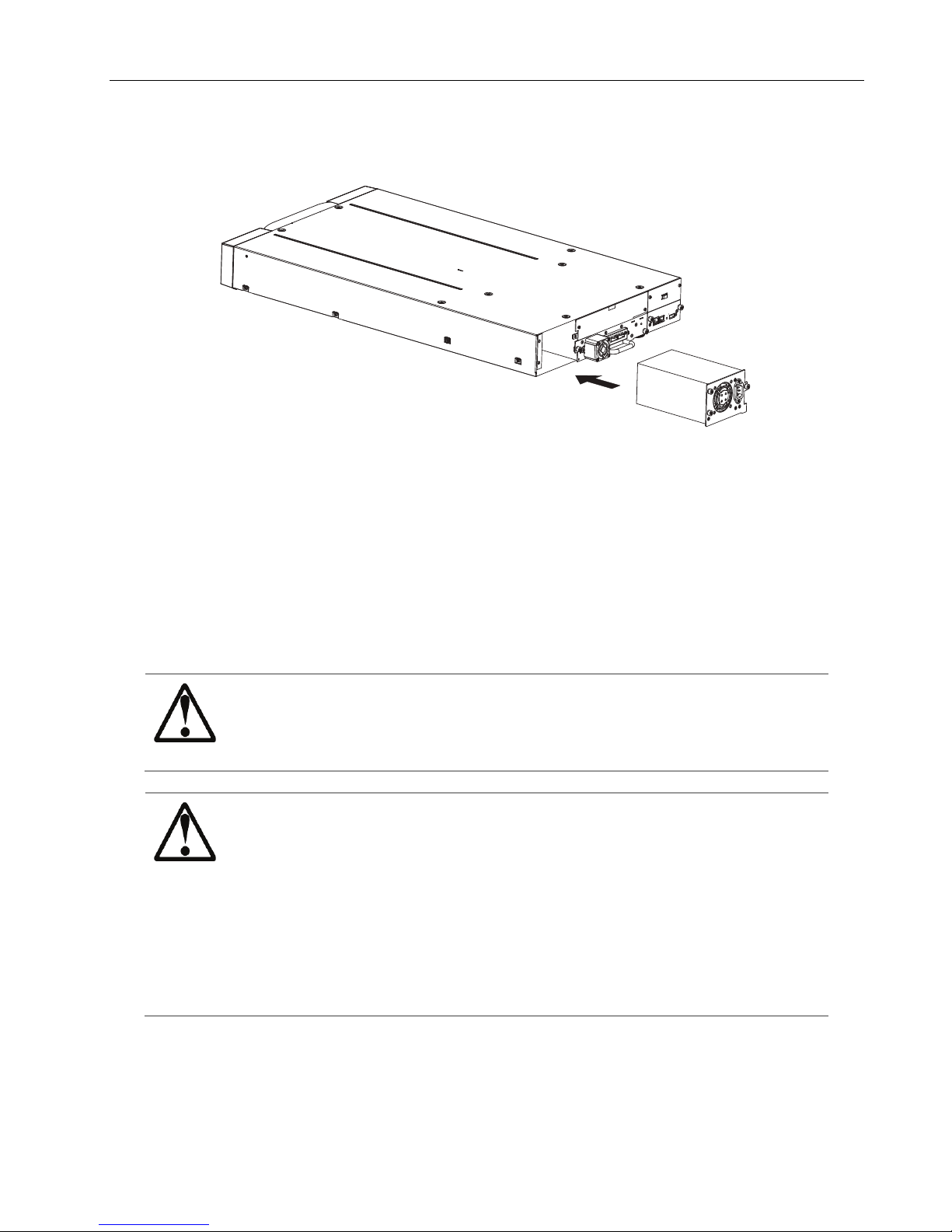
2.12.2 Connecting a Fibre Channel cable
Each FC tape drive has two FC ports.
Cable [Port A] only.
Configure [Port B] for <Auto Detect> on <Fibre Speed> and
To connect the FC cable to the tape drive:
1. Remove the FC port caps if necessary. Attach one end of the FC cable to [Port A] on the tape drive.
Figure 20 Connect the FC cable
2. Attach the other end of the FC cable to a switch or host bus adapter (HBA).
2.12.3 Connecting a SAS cable
Each SAS tape drive has a mini-SAS connector.
Mini-SAS connectors are keyed.
To connect the SAS cable to the tape drive:
1. Plug the HBA end of the SAS cable into the connector on the HBA.
• If you have a SAS fan-out cable, the end of the cable with only one connector, should be plugged
into the connector on the HBA.
Do not force a SAS cable’s mini-SAS connector into the tape
drive mini-SAS connector because it might be keyed differently.
SAS signal rates require clean connections and a minimum number
of connections between the HBA and the library.
Do not use adapters or converters between the HBA and the
library.
• If you are using a cable with a single connector on each end, plug the other end into the
connector on the tape drive.
• If you are using a SAS fan-out cable, plug one mini-SAS connector into the connector on each
tape drive. The unused ends of the SAS fan-out cable are single channel and not suitable for use
with disk arrays. Use the other ends to connect tape drives, or coil and secure them to the rack
to minimize stress on the connectors.
© Copyright QUALSTAR 2015 19

Q24/Q48 Tape Library Installation and Operations Manual
Tape drive generation
Tape cartridge type
LTO5 Ultrium LTO5, 1.5 TB data cartridge
Universal cleaning cartridge, (50 cleans)
LTO6
Ultrium LTO6, 2.5 TB data cartridge
Universal cleaning cartridge, (50 cleans)
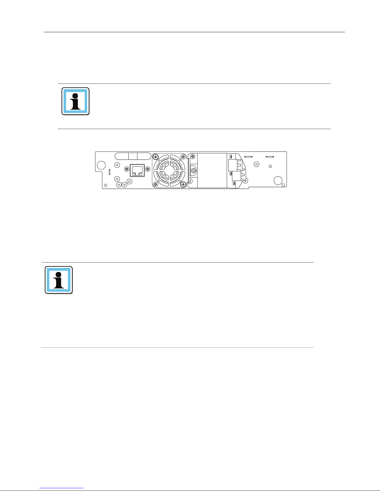
2.12.4 Connecting an Ethernet cable and a USB device
To connect the Ethernet cable to the library:
The connection to the Ethernet network is via an industry standard RJ45 copper interface on the rear
panel of the library. The Ethernet connection is used to access the library RMU over a network.
To connect the library to the Ethernet network, insert the Ethernet cable into the Ethernet port of the
library. When the plug is in the correct position, a click should be heard.
To connect the USB device to the library:
The USB port is on the rear of the library. It can be used for firmware upgrades/skin file updates
initiated via the operator control panel (OCP).
2.13 Verifying the host
When the host server is powered on, install the software and/or driver(s) that are compatible with the
library. Backup software packages may require additional software or licensing to communicate with
the library media changer.
To confirm that the host server’s operating system has recognized the library, consult the operating
system documentation.
2.14 Powering the library up or down
Press the power button on the front panel of the Q24 Tape Library to power it up or down. Powering
up can take a few minutes because it includes scanning the inventory and configuration (e.g. how many
and what type of drives are installed)
2.15 Tape cartridges
Before you begin using the library, an understanding of the media type, use, maintenance, and how to
properly label and write-protect your tape cartridges, will help you to prolong the life of your tapes as
well as the library.
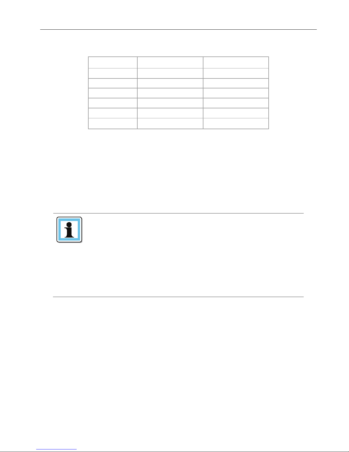
2.15.1 Tape cartridge type
The tape cartridge types supported depend on the drive types installed. The library will support any
type of LTO data cartridge and cleaning cartridge that the installed LTO drive will support.
© Copyright QUALSTAR 2015 20
Table 2 Tape cartridge type
Q24/Q48 Tape Library Installation and Operations Manual
LTO5 tape drive
LTO6 tape drive
LTO1 media
Incompatible
Incompatible
LTO2 media
Incompatible
Incompatible
LTO3 media
Read only
Incompatible
LTO4 media
Read / Write
Read only
LTO5 media
Read / Write
Read / Write
LTO6 media
Incompatible
Read / Write
NOTE
Do not degauss Ultrium LTO data cartridges! These data
unusable.
Table 3 Backward compatibility (tape cartridges)
Some tape drives include support for both rewriteable and WORM data cartridges. Write-Once, ReadMany (WORM) data cartridges provide an enhanced level of data security against accidental or
malicious alteration of data on the tape cartridge. The WORM data cartridge can have new data
appended to the maximum full capacity of the tape cartridge, but the user will be unable to erase or
overwrite any data previously recorded to the cartridge.
2.15.2 Using and maintaining tape cartridges
cartridges are pre-recorded with a magnetic servo signal. This
signal is required in order to use the cartridge with Ultrium LTO
To ensure the longest possible life for your data cartridges follow these guidelines before using the
library:
• Use only the data cartridges that are designated for your model of the library
• Clean the tape drive when the <Clean Drive> LED is illuminated. Be sure to use only Ultrium
universal cleaning cartridges.
• Do not drop an LTO data cartridge. Excessive shock can damage the internal contents of the tape
cartridge, or the tape cartridge case itself, making that tape cartridge unusable.
tape drives.
Keep Ultrium LTO cartridges separated from strong magnetic
fields such as computer monitors, electric motors, speakers, or
X-ray equipment.
Exposure to electromagnetic energy or magnetic fields can
destroy data and the embedded servo code written on the media
by the cartridge manufacturer, which can render the cartridge
• Do not expose your data cartridges to direct sunlight or sources of heat, including portable heaters
and heating ducts.
• The operating temperature range for your data cartridges is 10 to 35º C. The storage temperature
range is -40 to +60º C in a dust-free environment in which relative humidity is always between 20
percent and 80 percent (non-condensing).
© Copyright QUALSTAR 2015 21
 Loading...