

Qualstar Q40 Installation And Operation Manual
Q40™ Tape Library
Installation and Operations Manual
Document No. 511026 Rev. 07-01-19
1

Q40 Tape Library Installation and Operations Manual
Date
Issue
Revision
Author
Description of changes
2018-08-01
Initial release
01
Kevin Yi
Copyright
© Copyright 2018, QUALSTAR. All rights reserved. This document and the information contained herein
are the property of QUALSTAR. No part of this document may be reproduced, transmitted, transcribed,
stored in a retrieval system, or translated into any language or computer language in any form or by any
means, electronic, mechanical, magnetic, optical, manual, or otherwise, without the express written
permission of QUALSTAR.
Trademark Notices
QUALSTAR makes no representation or guarantees with respect to the contents of this document and
specifically disclaims any implied warranties of merchantability or fitness for any particular purpose.
Further, QUALSTAR reserves the right to revise this publication without obligation of QUALSTAR to notify
any person or organization of such revision or changes.
Q40™ i
s a Trademark of Qualstar Corporation
Revision History
2019-07-01
Contacting Qualstar
Sales
Qualstar Corporation
1267 Flynn Road
Camarillo, CA 93012
07-01-19 Kevin Yi
Address updated
Te
l: 805-583-7744
877-886-2758 (Toll Free)
Technical Support
Email: Support@qualstar.com
Tel: 805-416-7055
For non
http://www.qualstar.com/service-requests/
511026 Rev. 07-01-19 2
-urgent questions, please use the form on our website at:

Product warranty caution
The Q40 Tape Library contains no user-serviceable components. Only an authorized service center
should carry out any servicing or repairs. The warranty for the tape library shall not apply to failures of
any unit when:
• Any of the tape library components is repaired or modified by anyone other than Qualstar’s
personnel or approved agent. Note: Certain components of the Q40 Tape Library, are identified
i
n this manual as ‘field replaceable’. These include the power supply, tape drives, library
controller and magazines. User replacement of such complete components with corresponding
parts supplied by Qualstar does not affect warranty, provided the user strictly adheres to th
nstructions herein.
i
e
• The tape library is physically abused, or used in a manner that is inconsistent with the operatin
i
nstructions or product specification defined by Qualstar.
• The tape library fails because of accident, misuse, abuse, neglect, mishandling, misapplication,
alteration, faulty installation, modification, or service by anyone other than the factory service
c
enter or its approved agent.
• The tape library is repaired by anyone, including an approved agent, in a manner that is contrary
to the maintenance or installation instructions supplied by Qualstar.
• The manufacturer's serial number tag is removed.
• The tape library is damaged because of improper packaging on return.
In case of unauthorized repairs or modifications, your warranty becomes immediately void.
g
511026 Rev. 07-01-19
3

Q40 Tape Library Installation and Operations Manual
Table of Contents
1 Introduction ....................................................................................................................... 8
1.1 General Warnings ......................................................................................................................... 8
1.2 General Product Warnings: ........................................................................................................... 8
2 Product Overview .............................................................................................................11
2.1 Supported Library Configurations – Rackmount Installation ....................................................... 11
2.2 Supported Tape Drives ............................................................................................................... 14
2.3 Front Panel .................................................................................................................................. 15
2.4 Rear Panel .................................................................................................................................. 16
2.5 LTO-6/7/8 HH SAS Dual Port ...................................................................................................... 17
2.6 LTO-6/7/8 HH FC Single Port ..................................................................................................... 17
2.7 LTO-6/7/8 HH FC Dual Port ........................................................................................................ 17
2.8 Power Supply Rear Panel LEDs ................................................................................................. 18
2.9 Element Numbering .................................................................................................................... 18
3 Installing the Library ........................................................................................................19
3.1 Planning Installation .................................................................................................................... 19
3.2 Location Requirements ............................................................................................................... 19
3.3 SAS Configuration Requirements ............................................................................................... 20
3.4 Fibre Channel Configuration Requirements ................................................................................ 21
3.5 Planning Module and Rack Layout ............................................................................................. 22
3.6 Internal IP Range Selection ........................................................................................................ 22
3.7 Host Preparation ......................................................................................................................... 23
3.8 Installation Precautions ............................................................................................................... 23
3.9 Unpacking Base Module and Expansion Modules...................................................................... 24
3.10 Identifying Library Module Components ..................................................................................... 27
3.11 Preparing Top and Bottom Modules ........................................................................................... 27
3.12 Installing Modules in a Rack ....................................................................................................... 30
3.13 Aligning and Connecting Modules .............................................................................................. 32
3.14 Installing Tape Drives .................................................................................................................. 33
3.15 Connecting Fibre Channel Cables .............................................................................................. 33
3.16 Connecting SAS Cables .............................................................................................................. 33
3.17 Powering On the Library ............................................................................................................. 34
3.18 Using the Configuration Wizard .................................................................................................. 34
3.19 Verifying the Host Connection..................................................................................................... 34
511026 Rev. 07-01-19 4

Labeling Tape Cartridges ............................................................................................................ 35
20
3.
3.21 Write Protecting Tape Cartridges ................................................................................................ 36
3.22 Tape Cartridges .......................................................................................................................... 37
3.23 Read and Write Compatibility ...................................................................................................... 38
3.24 Loading Tape Cartridges ............................................................................................................. 39
3.25 Using the Mailslot ........................................................................................................................ 40
3.26 Bulk Loading Magazines ............................................................................................................. 40
4 Initial Setup of the Library................................................................................................42
4.1 Using the OCP ............................................................................................................................ 42
4.2 Using the RMI.............................................................................................................................. 42
4.3 Logging into the Library ............................................................................................................... 43
4.4 Using the Initial Configuration Wizard on the OCP ..................................................................... 44
5 Operating the Library using the Operator Panel ............................................................45
5.1 Login ............................................................................................................................................ 46
5.2 Magazine Buttons ....................................................................................................................... 47
5.3 Operation ..................................................................................................................................... 48
5.4 Configuration ............................................................................................................................... 50
5.5 Maintenance ................................................................................................................................ 62
5.6 Status .......................................................................................................................................... 70
6 Operating the library using the RMI ................................................................................74
6.1 Using the Library Main Screen with the RMI ............................................................................... 74
6.2 Configuring the Library with the RMI ........................................................................................... 76
6.3 Configuring the Library Network Settings ................................................................................... 79
6.4 Enabling or Disabling Mailslots ................................................................................................... 85
6.5 Configuring Library Partiti o ns ...................................................................................................... 85
6.6 Configuring Web Management Options ...................................................................................... 92
6.7 Maintaining the Library on the RMI ............................................................................................. 95
6.8 Viewing Log Files ........................................................................................................................ 99
6.9 Saving Log Files ........................................................................................................................ 100
6.10 Managing System Firmware ..................................................................................................... 100
6.11 Managing Drive Firmware ......................................................................................................... 101
6.12 Downloading Drive Logs ........................................................................................................... 101
6.13 Downloading Library Log and Trace Files ................................................................................ 102
6.14 Rebooting the Library ................................................................................................................ 102
6.15 Rebooting Drives ....................................................................................................................... 102
511026 Rev. 07-01-19
5

Q40 Tape Library Installation and Operations Manual
Controlling the UID LEDs .......................................................................................................... 103
6.
16
6.17 Moving the Robotic Assembly to the Base Module................................................................... 103
6.18 Operating the Library with the RMI ........................................................................................... 104
6.19 Viewing Status Information on the RMI ..................................................................................... 108
7 Upgrading and Servicing the Library ............................................................................ 119
7.1 Possible Tools Needed ............................................................................................................. 119
7.2 Identifying a Failed Component ................................................................................................ 119
7.3 Installing or Replacing a Tape Drive ......................................................................................... 119
7.4 Adding an Expansion Module ................................................................................................... 121
7.5 Removing the Library ................................................................................................................ 123
7.6 Replacing a Power Supply ........................................................................................................ 124
7.7 Replacing a Controller Board .................................................................................................... 125
7.8 Installing or Replacing a Drive Power Board ............................................................................ 127
7.9 Replacing a Module (Base or Expansion) ................................................................................. 129
7.10 Replacing the Robotic Assembly and Spooling Mechanism ..................................................... 133
7.11 Replacing the Front Bezel or OCP ............................................................................................ 138
8 Library Troubleshooting ................................................................................................ 140
8.1 Fibre Channel Connection Problems ........................................................................................ 140
8.2 Detection Problems after Installing a SAS Drive ....................................................................... 140
8.3 Operation Problems .................................................................................................................. 142
8.4 Performance Problems ............................................................................................................. 145
8.5 Finding Event Information ......................................................................................................... 147
8.6 Unlocking the Magazine ............................................................................................................ 147
8.7 Unloading a Stuck Tape ............................................................................................................ 149
8.8 Returning the Robotic Assembly to the Base Module .............................................................. 149
8.9 Running Library Tests ............................................................................................................... 151
9 Acronyms and Abbreviations ........................................................................................ 152
10 Event Codes................................................................................................................ 153
Technical Specifications ............................................................................................ 171
11
12 Regulatory Information .............................................................................................. 176
511026 Rev. 07-01-19 6

T
his page intentionally left blank
511026 Rev. 07-01-19
7
Q40 Tape Library Installation and Operations Manual
WARNING
Indicates that failure to follow directions could result in bodily harm or
death.
CAUTION
Indicates that failure to follow directions could result in damage to
!
IMPORTANT
Provides clarifying information or specific instructions.
NOTE
Provides additional information.
TIP
Provides helpful hints and shortcuts.
DANGER
High voltage
1 Introduction
Document Purpose
This manual provides information about installing, operating, troubleshooting and servicing a Qualstar
Q40 Tape Library. It is intended for system administrators and general users who need physical and
functional knowledge of the Q40 Tape Library.
The main components are
Base library: 800-0016-9
Expansion module: 800-0017-7
his document uses the reference Q40 to refer to the Q40 Tape Library.
T
1.1 General Warnings
Document Conventions:
equipment or data.
1.2 General Product Warnings:
Risk of electric shock
• Do not remove covers (top, bottom or rear). No userserviceable parts are inside.
• Refer servicing to qualified service personnel.
511026 Rev. 07-01-19 8
MECHANICAL
HAZARD
Danger
WARNING
Product Weight
CAUTION
Static Sensitive
NOTE
• Ventilation – Place the prod uc t in a location that does not interfere
• Risk of hand pinching, can trap hands, fingers and cause
erious injury. Keep hands clear during operation.
s
Risk of personal injury
Before lifting a library:
• Observe local health and safety requirements and guidelines
for manual material handling.
• Remove all tapes to reduce the weight.
• Remove all tape drives to reduce the weight.
• Obtain adequate assistance to lift and stabilize the library
during installation or removal.
Risk of damage to devices
When placing a library into or removing the library from a rack:
• Extend the rack’s levelling jacks to the floor.
• Ensure that the full weight of the rack rests on the levelling
jacks.
• Install stabilizing feet on the rack.
• Extend only one rack component at a time.
Risk of damage to devices
• A discharge of static electricity damages static-sensitive
ices or micro circuitry.
dev
• Proper packaging and grounding techniques are necessary
precautions to prevent damage.
with proper ventilation.
• Heat – Place the product in a location away from heat sources.
• Power sources – Connect the product to a power source only of t
t
ype directed in the operating instructions or as marked on t
product.
• Power cord protection – Place the AC line cord so that it is not
possible to be walked on or pinched by items placed upon or
against it.
• Object and liquid entry – Insure that objects do not fall onto and tha
l
iquids are not spilled into the product’s enclosure.
he
he
t
511026 Rev. 07-01-19
9

Q40 Tape Library Installation and Operations Manual
WARNING
Only trained personnel should operate this equipment. Read all
documentation and procedures before installation or operation. This
product is intended for installation and operation in a computer rack with
the front and rear doors closed and secured. Only personnel with
technical and product safety training should be provided access to the
library. Such personnel are referred to as users throughout this
document. Do not insert any tools or any part of your body into openings
of an operating system.
511026 Rev. 07-01-19 10
2 Product Overview
The Qualstar Q40 is a 3U highly scalab le li brar y syste m . The Q40 is expa nd able, al lowin g a us er t o gro w
their tape storage capacity as their data requirements increase.
ll Q40 insta lla tions beg in with t he 3U Base Module, with capacit y for 32 ta pe c a r tr idges a nd 3 h alf-height
A
LTO tape drives.
Each Expansion Module provides an additional 40 tape cartridges and supports an additional 3 halfheight LTO tape drives.
p to 6 Expansion Modules c an be added to a Base Module, bringing the total library capacity to 272
U
tape cartridges and 21 half-height LTO tape drives.
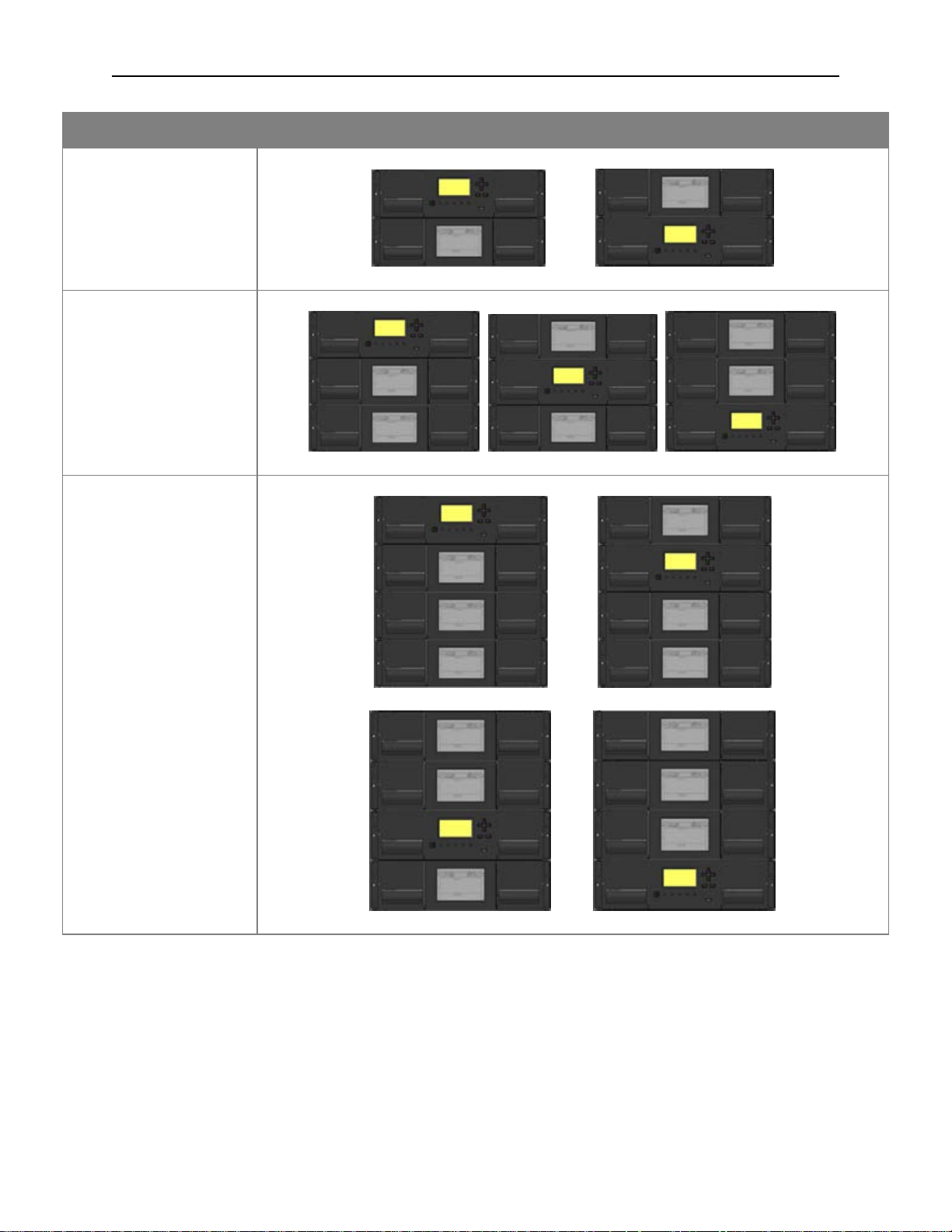
2.1 Supported Library Configurations – Rackmount Installation
All Q40 Libraries start with a Base Module. Up to 6 Expansion Modules can be added as needed to
support customer requirements. The architecture has been designed to support a maximum of 3
Expansion Modules above and 3 Expansion Modules below. The Base Module must be mounted with 9U
of empty space above and 9U of empty space below to ensure a full stack can be installed. Table 1
shows the supported configurations for libraries ranging from one to seven total modules.
T
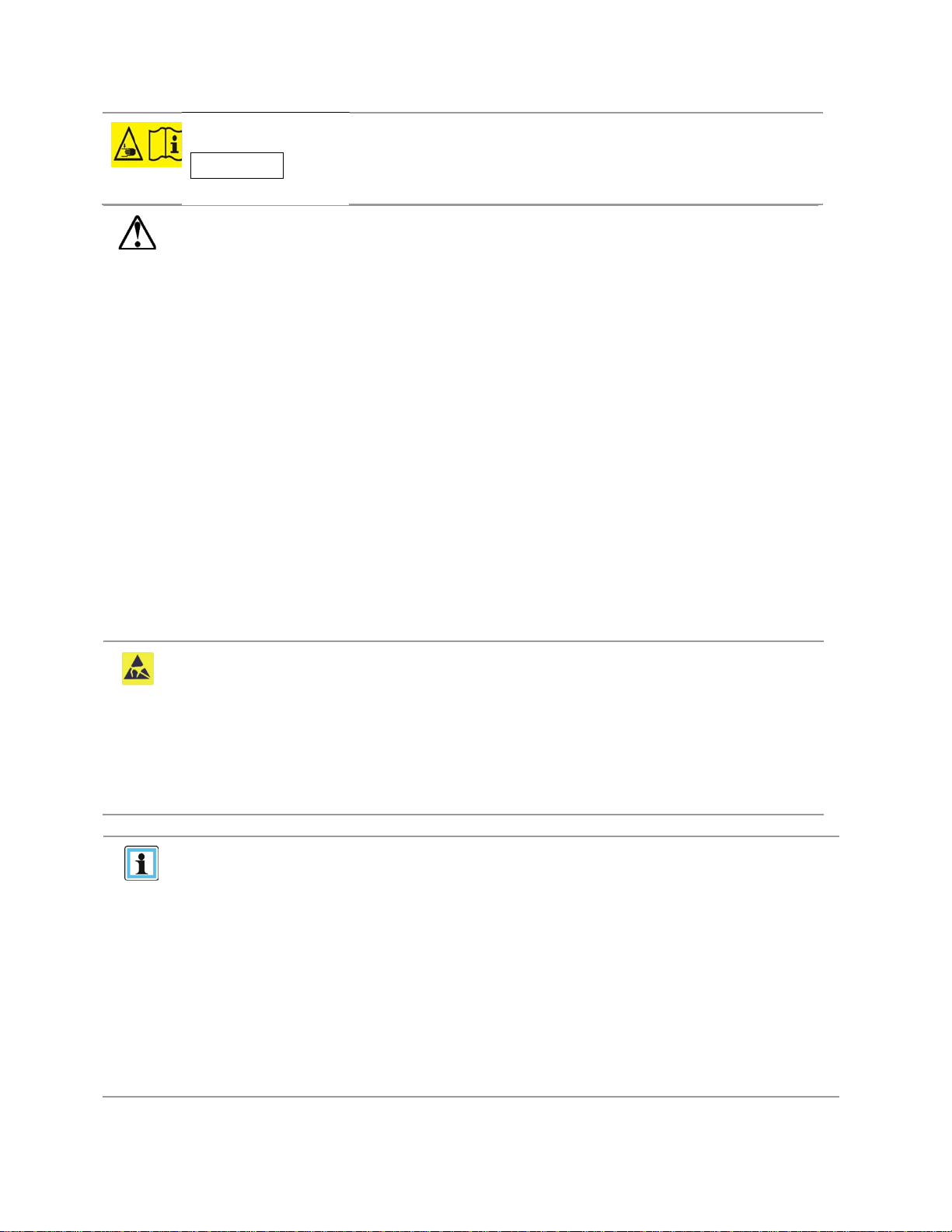
he Base Module is depicted by the following image with the Operator Control Panel shown in yellow:
ach Expansion Module is represented by the following image with a large clear viewing window in the
E
center.
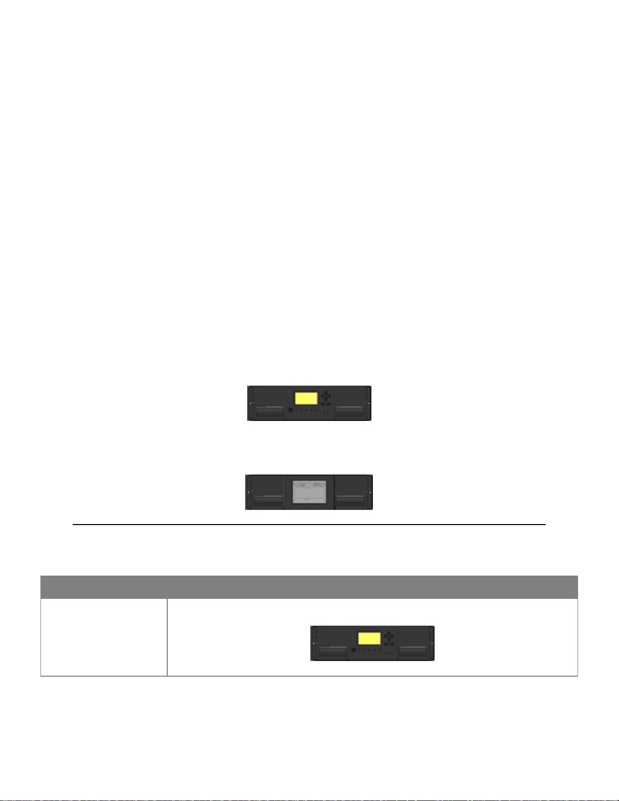
able 1: Supported Library Configurations
T
Module Quantity Supported Library Co nfigurations
1 Module Library
Base Module
511026 Rev. 07-01-19
11
Q40 Tape Library Installation and Operations Manual
Module Quantity Supported Library Co nfigurations
2 Module Library
Base Module
1 Expansion Module
3 Module Library
Base Module
2 Expansion Modules
4 Module Library
Base Module
3 Expansion Modules
511026 Rev. 07-01-19 12
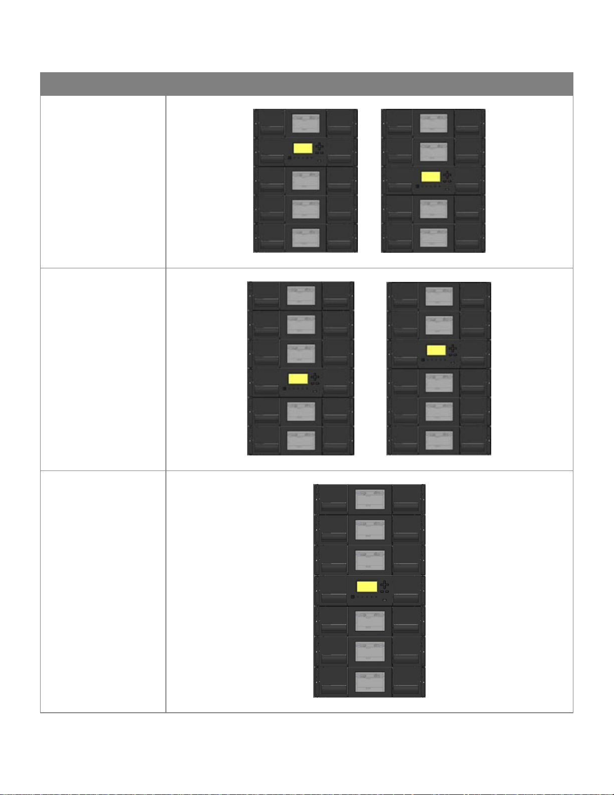
Module Quantity Supported Library Co nfigurations
5 Module Library
Base Module
4 Expansion Modules
6 Module Library
Base Module
5 Expansion Modules
7 Module Library
Base Module
6 Expansion
Modules
511026 Rev. 07-01-19
13

Q40 Tape Library Installation and Operations Manual
2.2 Supported Tape Drives
The Q40 was developed to integrate industry-standard LTO Ultrium tape drives. Mixed drive generations
and mixed interfaces are supported within a single library and within a single module.
Listed below in Table 2 are the tape drives that have been tested and implemented in the Q40.
able 2: Supported Tape Drives
T
LTO Drives
LTO-6 Half-Height FC Single Port
LTO-6 Half-Height FC Dual Port
LTO-6 Half-Height SAS Du al Port
LTO-7 Half-Height FC Single Port
LTO-7 Half-Height FC Dual Port
LTO-7 Half-Height S AS Du al Port
LTO-8 Half-Height FC Single Port
LTO-8 Half-Height FC Dual Port
LTO-8 Half-Height SAS Du al Port
511026 Rev. 07-01-19 14
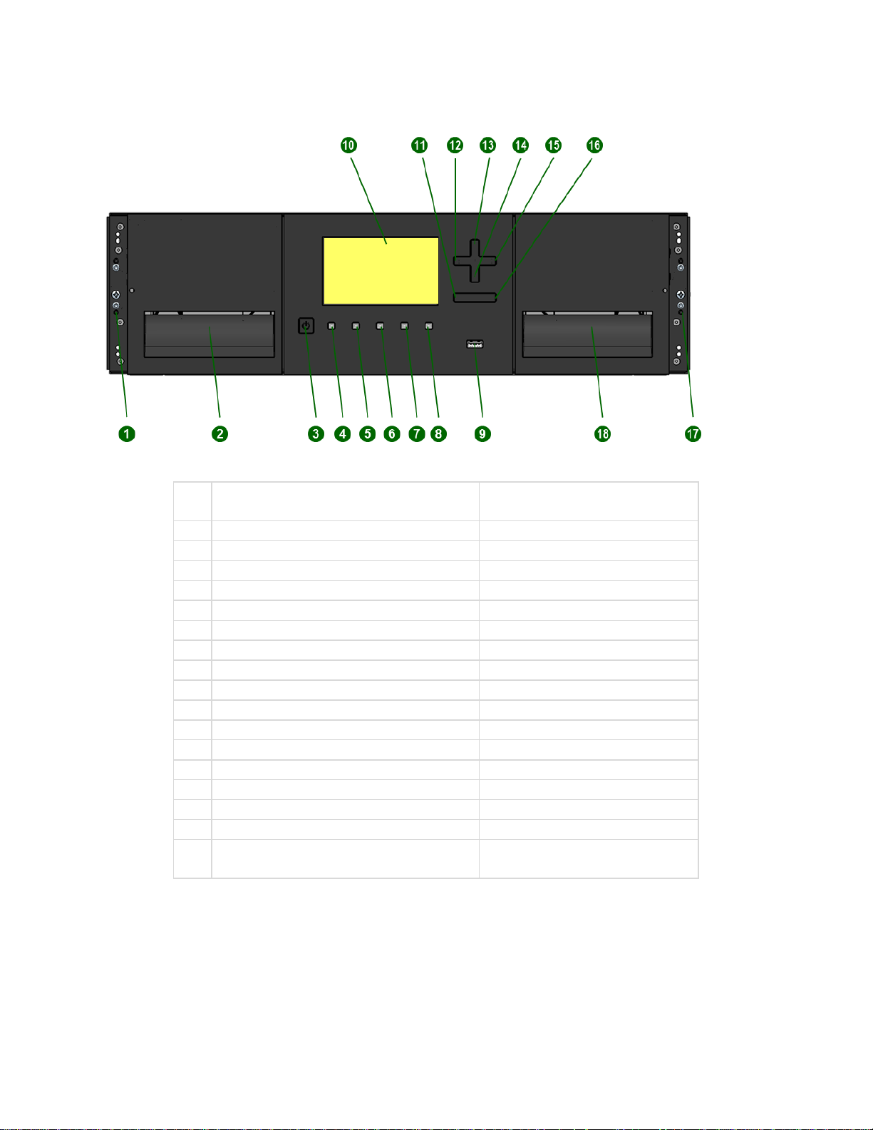
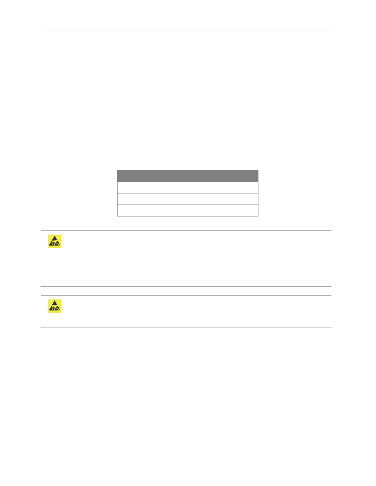
2.3 Front Panel
1
Left Magazine Emergency Release
Access Hole
2
Left Magazine Access Handle
3
Power Button
Base Module Only
4
Unit Identification LED, Blue
Base Module Only
5
Ready LED, Green
Base Module Only
6
Clean LED, Amber
Base Module Only
7
Attention LED, Amber
Base Module Only
8
Error LED, Amber
Base Module Only
9
USB Port
Base Module Only
10
Operator Control Panel (OCP) Display
Base Module Only
11
Back/Return Button
Base Module Only
12
Navigation Button - Left
Base Module Only
13
Navigation Button – Up
Base Module Only
14
Navigation Button – Down
Base Module Only
15
Navigation Button – Right
Base Module Only
16
Enter Button
Base Module Only
17
Mailslot/Right Magazine Access Handle
18
Right Magazine Emergenc y Releas e
Access Hole
511026 Rev. 07-01-19
15
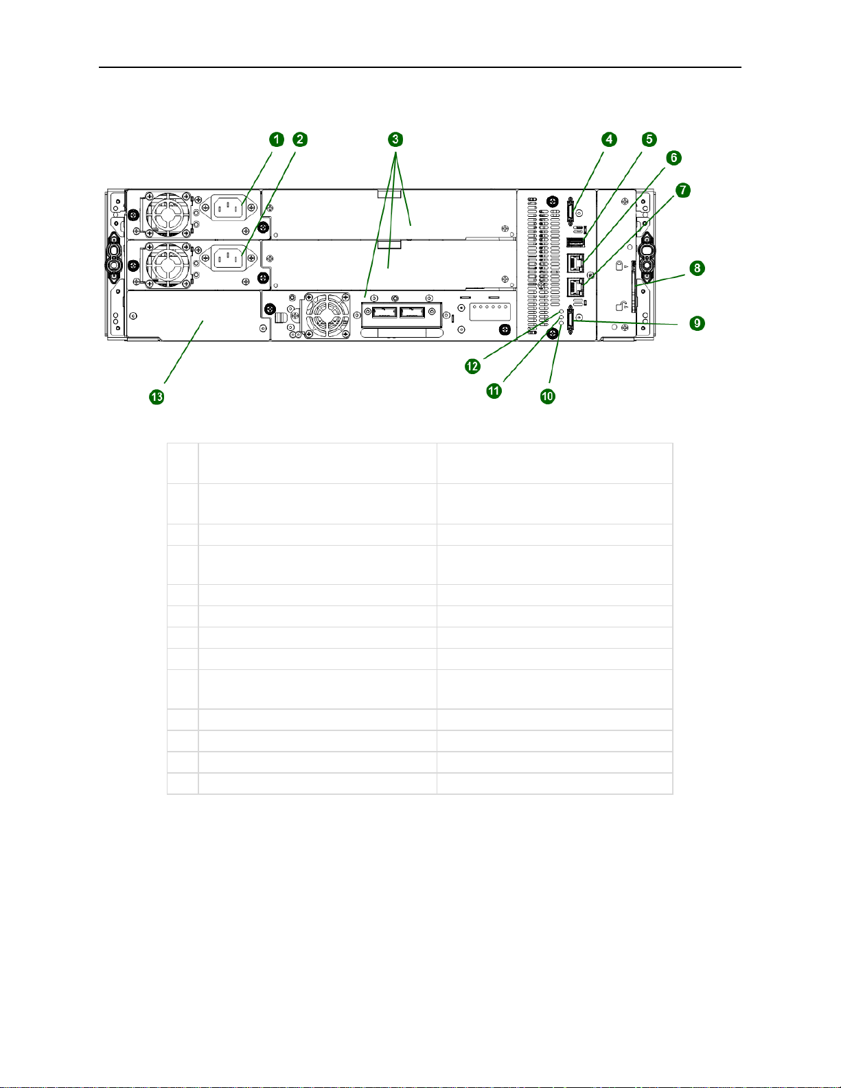
Q40 Tape Library Installation and Operations Manual
1
Power Supply 1
Standard on Base Module
2
Power Supply 2
Optional on Base Module
3
Half-Height Tape Drive Bays
4
Upper Expansion Module
5
USB Port
Optional on Base Module Only
6
Ethernet Port A
Base Module Only
7
Ethernet Port B
Optional on Base Module Only
8
Module Alignment Mechanism
9
Lower Expansion Module
10
Unit Identifier LED, Blue
11
Controller Error LED, Yellow
12
Controller Health Status LED, Green
13
Product Serial Number Tag Location
2.4 Rear Panel
Connection Port
Connection Port
Optional on Expansion Module
Optional on Expansion Module
511026 Rev. 07-01-19 16
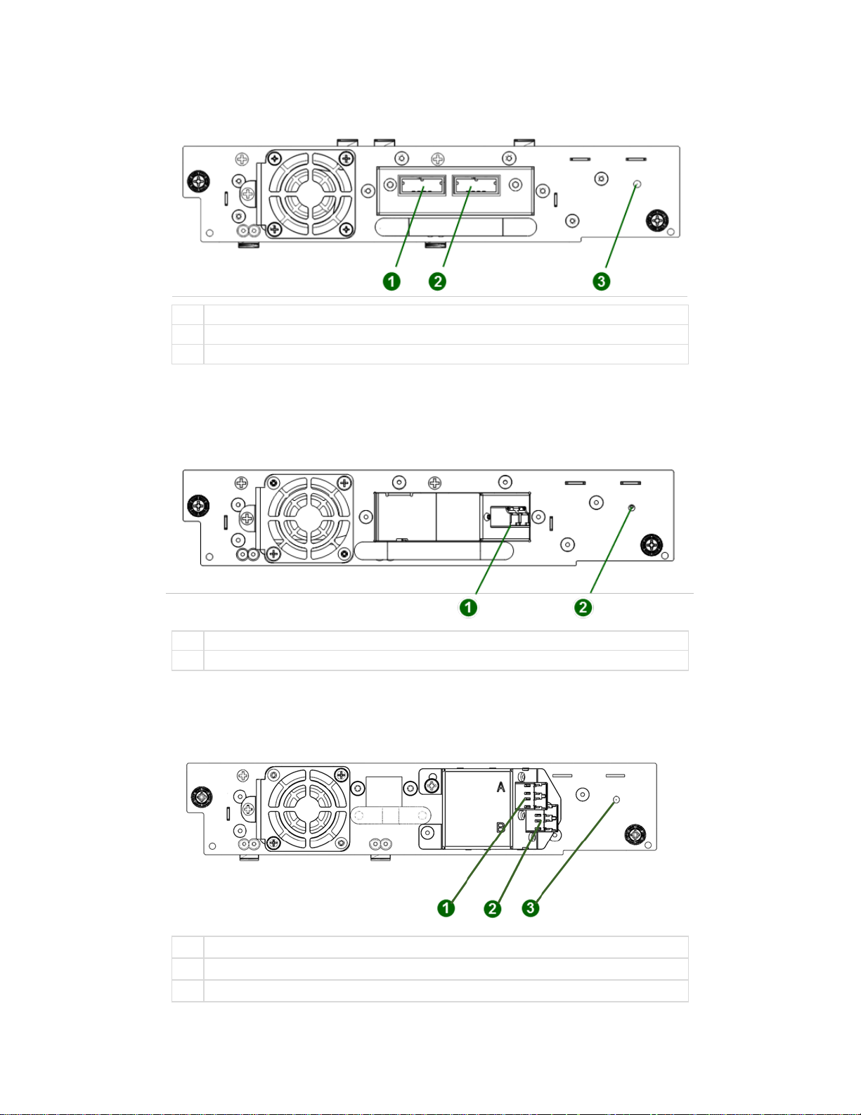
2.5 LTO-6/7/8 HH SAS Dual Port
1
SAS Port A
2
SAS Port B
3
Tape Drive Power LED, Green
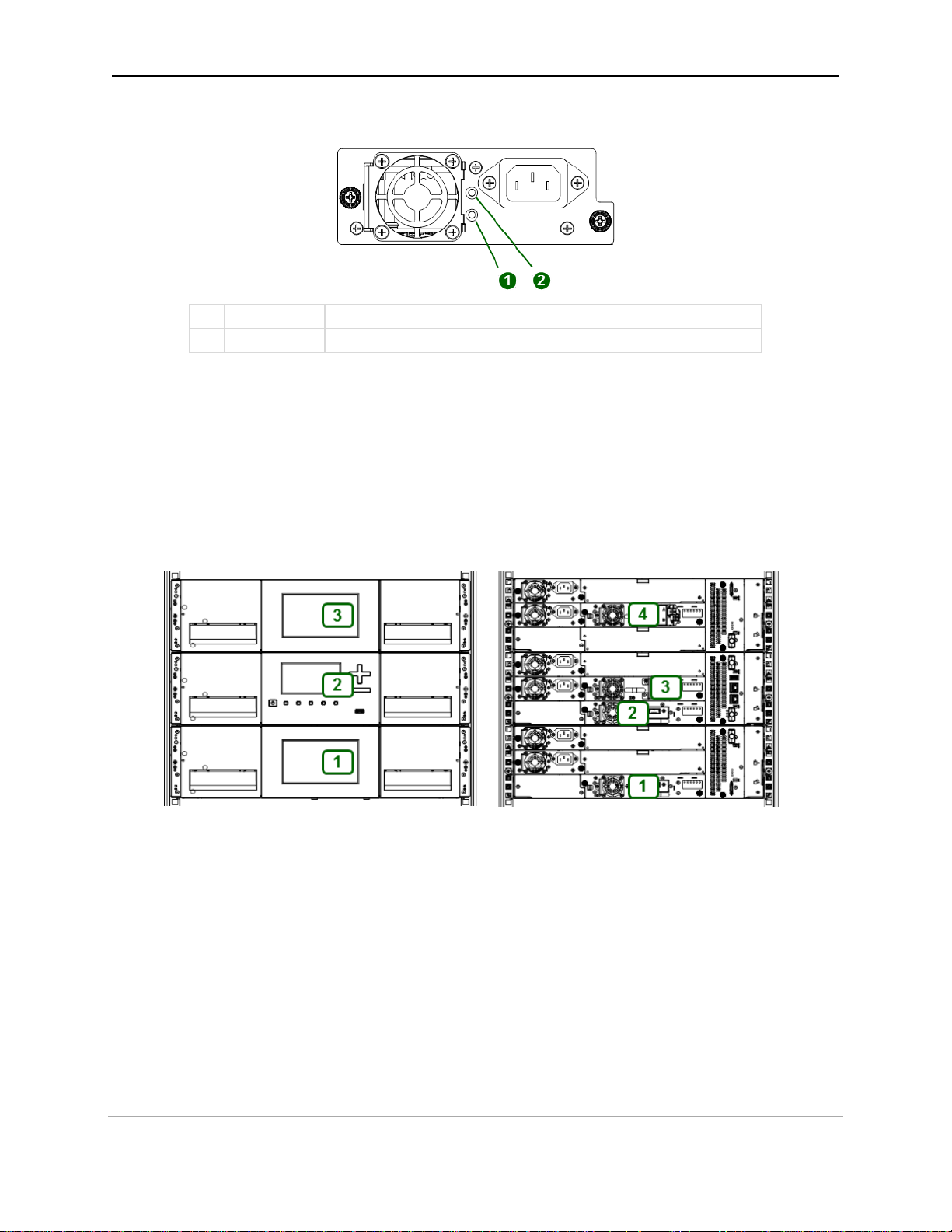
1
FC Port A
2
Tape Drive Power LED, Green
1
FC Port A
2
FC Port B
3
Tape Drive Power LED, Green
2.6 LTO-6/7/8 HH FC Single Port
2.7 LTO-6/7/8 HH FC Dual Port
511026 Rev. 07-01-19
17
Q40 Tape Library Installation and Operations Manual
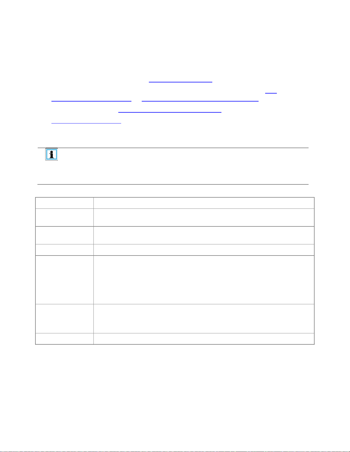
1
White
AC power connected, but Module Powered Off
2
Green
Module Powered On
2.8 Power Supply Rear Panel LEDs
2.9 Element Numbering
T
he library will generally display logical element numbering of modules, storage slots and tape drives
starting with number one from the bottom up.
511026 Rev. 07-01-19 18
3 Installing the Library
NOTE
•
AC Power Voltage: 100-240 VAC
Place the library in an area with minimal sources of particulate contamination
Excessive dust and debris can damage tapes and tape drive
3.1 Planning Installation
• Choose a location for the library. See “Location Requirements”.
• Plan the SAS or Fibre Channel configuration and obtain the necessary cables. See “SAS
Configuration Requirements” or “Fibre Channel Configuration Requirements”.
• Plan the rack layout. See “Planning the Module and Rack Layout”.
• Internal IP Range Selection
3.2 Location Requirements
The library was designed for rack installation.
• Rack installations must use the provided rack rails.
• Select a location with access to the host server.
• Choose a location that meets the criteria in the table below.
Table 3: Location Requirements
Criteria Definition
Rack Requirements
Rack Space
Requirements
Room Temperature 10-35º C (50-95º F)
Standard 19-inch rack (minimum depth of 1 meter) with an appropriate # of U’s
(Rack Units) of clearance for the planned module quantity
3U for the Base Module and 3U for each Expansion Module
Line Frequency: 50-60 Hz
Library Located near AC Outlet(s)
Power Source
The AC power cord is the library’s main AC disconnect device and must be easily
accessible at all times.
Air Quality
Humidity 20-80 percent RH non-condensing
Avoid areas near frequently used doors and walkways, stacks of supplies that
collect dust, printers, and smoke-filled rooms
511026 Rev. 07-01-19
19
Q40 Tape Library Installation and Operations Manual
CAUTION
High quality SAS cables rated at the transfer rate of the SAS drives are
CAUTION
The library has one or more mini-SAS connectors on each SAS tape
3.3 SAS Configuration Requirements
Serial Attached SCSI (SAS) is a computer bus technology mainly used to transfer data to and from
storage devices, including disk drives and tape drives. SAS is designed to transfer data at up to 6 Gbps.
SAS uses serial connections, with a direct connection between the host server and each of the storage
devices. This eliminates the need to configure SCSI busses and assign SCSI IDs, as is required for
parallel SCSI devices.
The host server must have a SAS Host Bus Adapter (HBA) with an external connector. The HBA uses
multiple Logical Unit Numbers (LUNs) to communicate with the library. Verify that your HBA supports
multiple LUNs. Please note, most RAID controllers do not have multiple LUNs support. Most SAS HBA
ports have four SAS channels. A tape drive uses one channel, so each HBA port can support up to four
tape drives. You can use a cable with one connector on each end, or a fan-out cable, which has one
connector on one end and up to four connectors on the opposite end. Supported speeds by drive
generation are shown in the table below.
able 4: Supported SAS Speeds
T
LTO Generation Supported Speeds
LTO-6 1.5 Gbps, 3 Gbps, 6 Gbps
LTO-7 1.5 Gbps, 3 Gbps, 6 Gbps
LTO-8 1.5 Gbps, 3 Gbps, 6 Gbps
required. Always verify that the SAS cable you are using is rated for the
data transfer speed of the interface of your components. SAS cables
described as "equalized" may not support 6 Gb/s data rates and should
not be used with LTO-6 or later generation tape drives unless these
cables are verified for 6 Gb/s data rates.
drive. Mini-SAS connectors are keyed. Do not force a SAS cable’s miniSAS connector into the tape drive as it might be keyed differently.
A SAS tape drive is identified by a unique identifier called a World Wide Name (WWN) or World Wide
Identifier (WWID). The library assigns the WWID to the drive bay. When a tape drive is replaced, the
WWID is re-assigned to the new tape drive.
The operating system tracks the WWID for the tape drive on each HBA channel. Each of the drive
connectors on the fan-out cable is associated with an HBA channel. Once a tape drive has been plugged
in, it should remain on the same channel to retain the association between the HBA channel and WWID.
511026 Rev. 07-01-19 20
3.4 Fibre Channel Configuration Requirements
NOTE
• Use an appropriate HBA for your tape drive to match performance
The Fibre channel tape drive can be connected directly to the server with a host bus adapter (HBA) or
through a storage area network (SAN).
The installation requires one Fibre Channel cable for each tape drive. The tape drives all utilize an LCstyle connector. Some drives will have two FC ports, but only one cable connection is needed per drive.
The cable can be connected to either drive FC port.
Supported speeds by drive generation are listed in the table below.
Table 5: Supported Fibre Channel Speeds
LTO Generation Supported Speeds
LTO-6 2 Gbps, 4 Gbps, 8 Gbps
LTO-7 2 Gbps, 4 Gbps, 8 Gbps
LTO-8 2 Gbps, 4 Gbps, 8 Gbps
requirements.
• A lower Gbps HBA might result in performance degradation when
oving highly compressible data to a higher Gb tape drive.
m
• In a SAN installation, all switches between the host and the library must
be of the appropriate type.
• A lower Gb switch in the path may result in performance degradation.
Configure zoning so only the backup servers may access the library.
511026 Rev. 07-01-19
21
Q40 Tape Library Installation and Operations Manual
3.5 Planning Module and Rack Layout
If possible, install the Base Module in the middle of the rack to provide space for the permitted 3
Expansion Modules above and 3 Expans i on Mod ules below. See Table 1: Supported Library
Configurations for additional details.
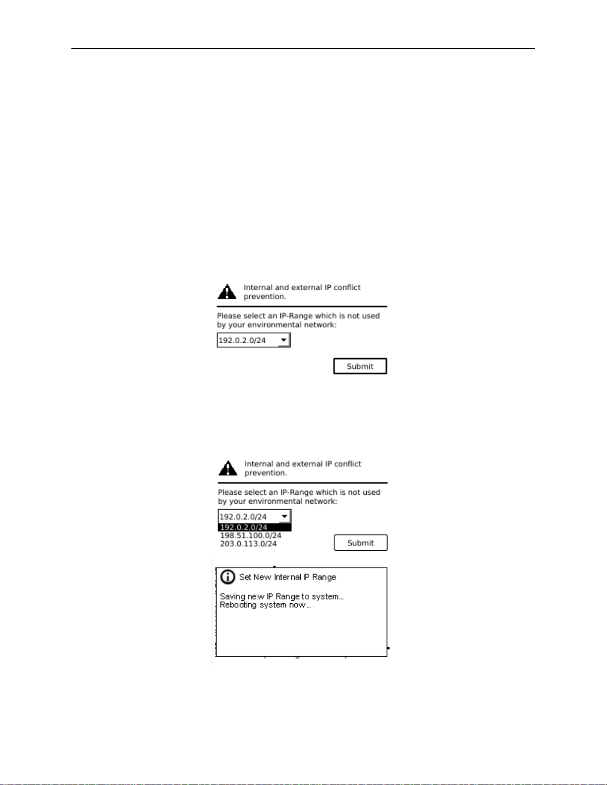
3.6 Internal IP Range Selection
For internal communication between modules the tape library uses an Ethernet connection with an
internal IP address range. To prevent any conflict between the internal IP address range and the external
IP addresses it is required to select the internal IP range before the tape library gets connected to the
external Ethernet port.
Therefore, a file which contains the internal IP range is stored onto the Base Module backplane:
/opt/storage/mfg/stack/network.range and LCM /opt/storage/configurati on /network.range
The Values must be in the following format: RANGE=192.0.2
lease note: the last section of the IP address is not set because it will be set internally.
P
The file will be created through the Operator Control Panel (OCP) IP Range selection page when the
Stack starts for the very first time or if the unit was reset to Manufacturing Defaults / Reset via OCP or
Remote Management Interface (RMI).
511026 Rev. 07-01-19 22
3.7 Host Preparation
CAUTION
Static Sensitive
WARNING
Product Weight
CAUTION
• Do not expose the library to moisture.
Risk of damage to devices
• A discharge of static electricity damages static-sensitive devices or
micro circuitry.
• Proper packaging and grounding techniques are necessary
precautions to prevent damage.
Follow these general guidelines:
• Check with a system administrator before powering off the host computer.
• For a SAS library, confirm availability or install a SAS HBA that supports multiple LUNs.
• For a direct-attach Fibre Channel library, confirm availability of install an FC HBA.
• For connection of a Fibre Channel library through a compatible switch, verify that sufficient ports
are available.
3.8 Installation Precautions
Each Q40 module weighs m ore than 20 kg (44 lbs) without drives or
tapes and more than 35 kg (77 lbs) with 3 tape drives and 40 tapes.
isk of personal injury
R
Before moving or lifting a library:
• Observe local health and safety requirements and guidelines for
manual material handling.
• Remove all tapes to reduce the weight and to prevent cartridges
from falling into the robotics path and damaging the library.
• Remove all tape drives to reduce the weight.
• Obtain adequate assistance to lift and stabilize the library during
stallation or removal.
in
Risk of damage to devices
When placing a library into or removing the library from a rack:
• Extend the rack’s levelling jacks to the floor.
• Ensure that the full weight of the rack rests on the levelling jacks.
• Install stabilizing feet on the rack.
• Extend only one rack component at a time.
• Do not place a module on either the ends or sides as this may cause
age.
dam
511026 Rev. 07-01-19
23
Q40 Tape Library Installation and Operations Manual
CAUTION
If the temperature in the room where the library will operate varies by
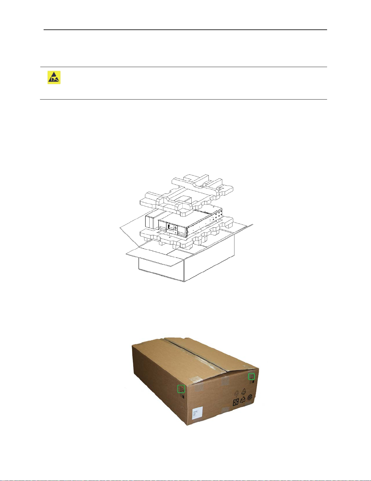
3.9 Unpacking Base Module and Expansion Modules
Before unpacking any modules, clear a work surface near the targeted rack for installation.
15° C (30° F) from where the module was stored, allow it to acclimate for
at least 12 hours prior to unpacking.
npacking a Q40 Base Library or Expansion Module:
U
1. Before opening and removing a module from the box, inspect the container for shipping damage.
2. If you notice any damage, report it to the shipping company immediately.
3. Overview of packaging.
4. Make sure the box is aligned properly before opening the box. The arrows on the box should be
pointing upwards.
511026 Rev. 07-01-19 24
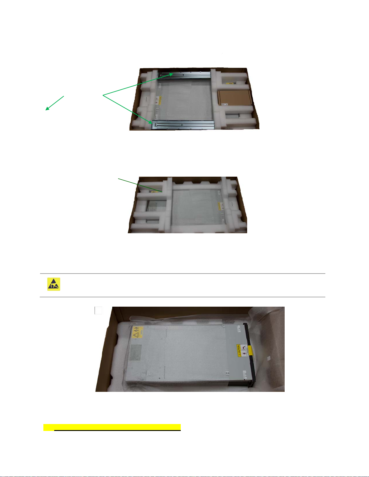
emove the rack rails and the accessory kit box.
CAUTION
Do not place a module on either the ends or sides as this may cause
Remove foam from top
Remove
Remove
5. R
rack rails
emove the foam pieces from the top of the module.
6. R
accessory kit box
With assistance, lift the module out of the bottom foam nest, remove the wrapping from the module
and then place the module on the work surface.
damage.
7. Save the packaging materials for future use.
511026 Rev. 07-01-19
25
Q40 Tape Library Installation and Operations Manual
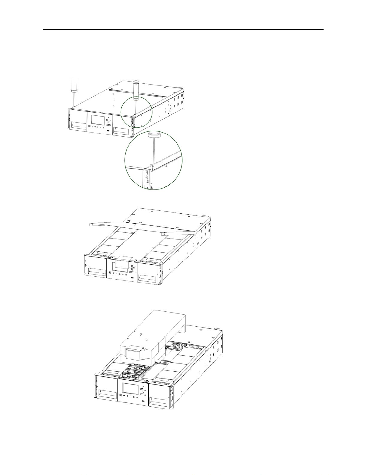
8. T
he robotics is protected during shipment by an insertion foam which has to be removed prior t
in
stallation
9. To remove the top cover plate from the Base Module, unlock the top cover using two small
screwdrivers.
10. Lift the cover front end and pull gently forward to disengage from the pivot point at the unit center
o
11. Remove the insertion foam.
511026 Rev. 07-01-19 26

f you are installing a Base Module only without an Expansion Module install the top cover again
CAUTION
Do not place a module on either the ends or sides as this may cause
12. I
he Base Module
t
13. If you want to install a library system with multiple modules see chapter “
Modules”
14. Save the packaging materials for future use.
damage.
Preparing Top and Bottom
on
3.10 Identifying Library Module Components
If you have unpacked a Base Module, confirm that you have received the following components:
1. Base Module
2. Two Rack Rails
3. Accessory Kit
a. One packet of rack mount hardware
b. One North American Power Cord
c. One European Power Cord
If you have unpacked an Expansion Module, confirm that you have received the following components:
1. Expansion Module
2. Two Rack Rails
3. Accessory Kit
a. One packet of rack mount hardware
b. Expansion Interconnect Cable
For SAS libraries, you must provide SAS cabling with the correct configuration for your HBA. For Fibre
Channel libraries, you must provide one Fibre Channel cable for each tape drive.
3.11 Preparing Top and Bottom Modules
Skip this step if you are installing a Base Module onl y without an Expansion Module.
The Base Module has removable top and bottom covers.
If you are installing one or more Expansion Modules above the Base Module, move the top cover from
the Base Module to the Expansion Module that will be installed at the top of the library.
If you are installing on or more Expansion Modules below the Base Module, move the bottom cover from
the Base Module to the Expansion Module that will be installed at the bottom of the library.
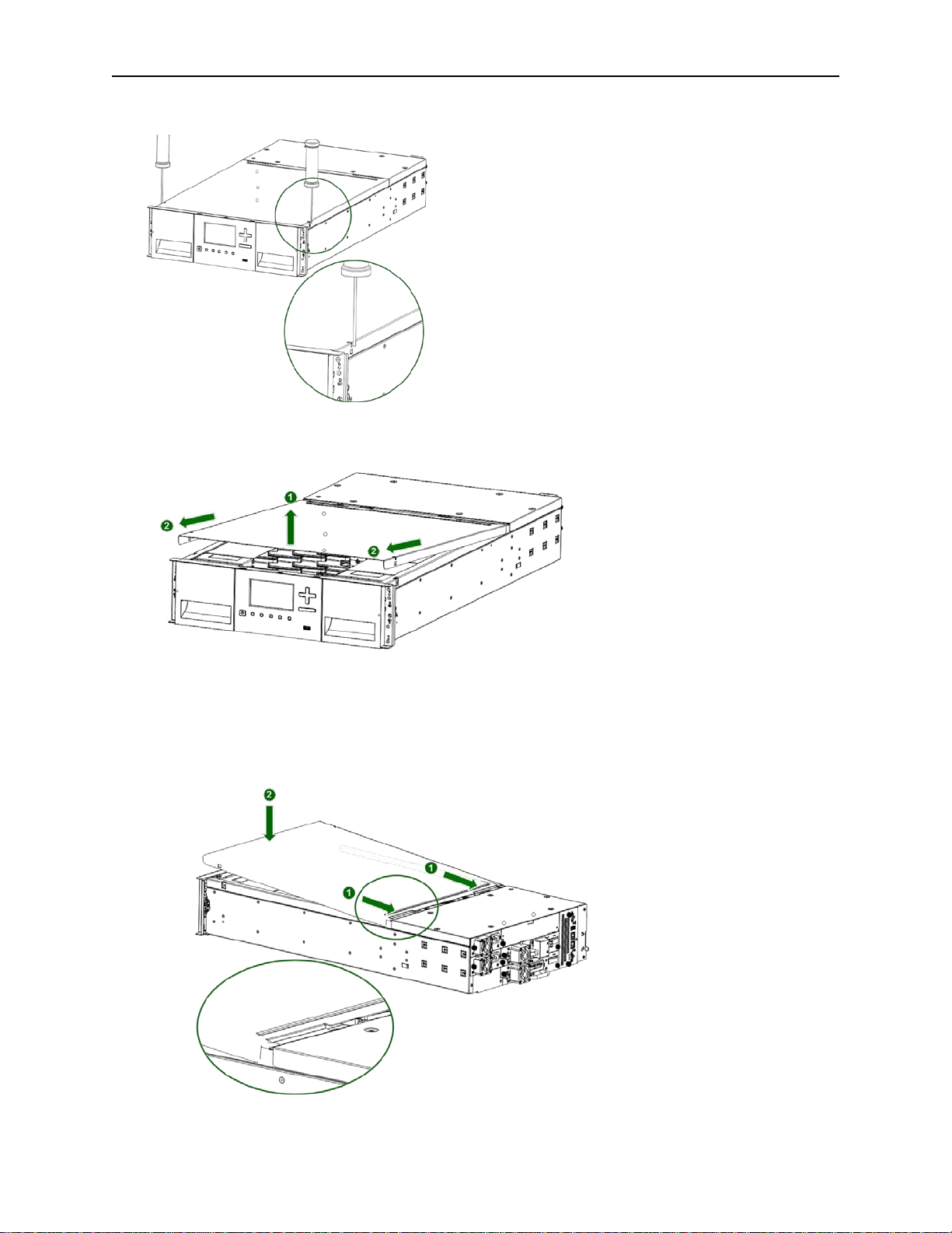
3.11.1 To move the library top cover plate from the Base Module to an Expansion
Module:
1. Remove the library top cover plate from the Base Module.
a. Place the Base Module on a work table
511026 Rev. 07-01-19
27
Q40 Tape Library Installation and Operations Manual
b. U
nlock the top cover using two small screwdrivers.
c. Lift the front end of the cover and pull gently forward to disengage from the pivot point at the unit
center.
2. Install top cover on the Expansion Module that will be installed on the top of the library.
a. Place the Expansion Module on a work table
b. With the front of the top cover raised, engage the rear of the cover at the Expansion Module pivot
point located at the back of the opening.
c. Lower the front of the top cover until the latches engage on both sides.
511026 Rev. 07-01-19 28
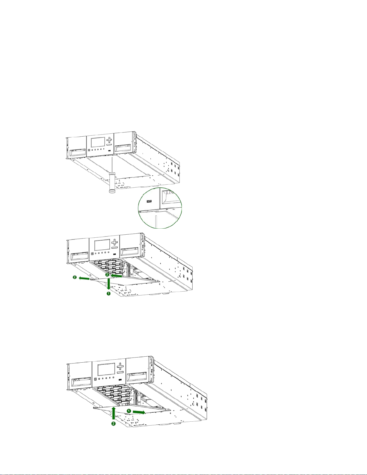
3.11.2 To move the library bottom cover plate from the Base Module to an Expansion
Module:
1. Remove the library bottom cover plate from the Base Module.
a. Place the Base Module on a work table
b. Lift the front end of the module (use module’s rear as a pivot edge)
c. Support the bottom cover with one hand. Insert a small flathead screwdriver or Torx screwdriver
into the hole and slide sidewards to unlock the spring loaded lock.
d. Lower the front end of the cover and pull gently forward to disengage from the pivot point at unit
center
e. Remove the cover from the module.
2. I
nstall the library bottom cover plate to the Expansion Module.
a. Place the Base Module on a work table
b. Lift the front end of the module (use unit rear as a pivot edge)
c. Insert the bottom cover at the center
d. Lift up the cover front edge until hard stop and it locks in at the module front.
511026 Rev. 07-01-19
29
Q40 Tape Library Installation and Operations Manual
3.12 Installing Modules in a Rack
Q40 modules are easy to install in racks compliant to the EIA 310A Standard, when at least 1 meter
deep. You need a #2 Phillips screwdriver for this process.
o locate the rail locations when installing multiple modules:
T
1. Locate the bottom of the lowest full U where the lowest module will be installed.
2. Continue identifying the locations for any additional module 3U higher.
T
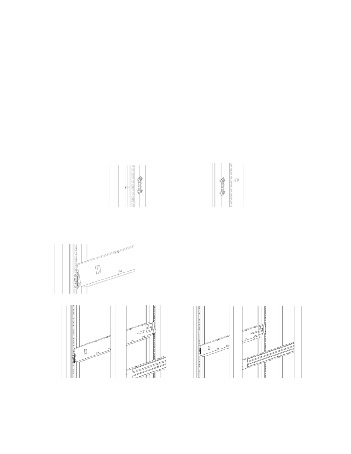
o install the rails into the rack, starting from the lowest rack location:
1. Locate the 4 adapter blocks, 4 Philips screws (Shipped in the accessory box) and 2 rackmount rails
(LH and RH).
2. On the front of the rack, mount an adapter block at the appropriate height to the right and left rack
posts. Mount them in the middle square hole of the height unit (The middle of a height unit is the hole
between two wide and neighboring division bars.).
3. Repeat step 2 on the right and left rack posts in the rear of the rack.
4. Mount the LH Rackmount rail to the adapter blocks.
5. Repeat step 4 with the RH Rackmount rail.
511026 Rev. 07-01-19 30
 Loading...