

Qualstar 501440 Rev. G, 501420-02-0, 648-0003-0, 648-0006-3 Installation And Operation Manual

TLS Fibre Channel
Installation and Operation
Option
Manual
501440 Rev. J

Important Manual/Firmware Revision Information
This manual and the operating firmware for the Tape Library System (TLS) are revised periodically as the product is improved. This manual was revised to correspond
with the firmware version indicated below. Do not use this manual with prior versions
of the firmware. Check with Qualstar Technical Support about use of this manual
with older or newer firmware.
Manual Corresponding Firmware
Fibre Channel
Installation and Operation Manual
501440 Rev. J, 16 March 2009
Copyright Notice
Copyright© 2009 by Qualstar Corporation — All Rights Reserved
Information contained in this document is copyrighted by Qualstar Corporation. It is
intended for use by Qualstar's customers and prospective customers to evaluate, integrate, operate and maintain Qualstar products. Customers and prospective customers
may reproduce this document as needed for these uses. Reproduction in whole or in
part for any other use or by any other party is prohibited without prior written permission from Qualstar Corporation.
TLS Executive Firmware
700105 Version: 2.26
Every effort has been made to keep the information contained in this document current and accurate as of the date of publication or revision. However, no guarantee is
given or implied that the document is error-free or that it is accurate concerning any
specification. Qualstar reserves the right to modify the design or specification without
notice.
Qualstar and the Qualstar logo are registered trademarks of Qualstar Corporation.
Chaparral is a registered trademark of Chaparral Network Storage, Inc.
All other trademarks are the property of their respective owners.
501440 Rev. J i

Notices
Qualstar products are covered by one or more of the following patents:
6,271,982 and 6,560,061. Other patents pending.
Qualstar equipment is manufactured from new parts, or new and used parts. In some
cases, Qualstar equipment may not be new and may have been previously installed.
Regardless, Qualstar’s warranty terms apply unless the equipment is specifically
identified by Qualstar as “used” or “refurbished”.
This equipment has been tested and found to comply with the limits for a Class A
computing device pursuant to Part 15 of the FCC Rules. These limits are designed to
provide reasonable protection against harmful interference when the equipment is operated in a commercial environment. This equipment generates, uses, and can radiate
radio frequency energy and, if not installed and used in accordance with the instructions manual, may cause harmful interference to radio communications. Operation of
this equipment in a residential area may cause unacceptable interference to radio and
TV reception in which case the user, at his own expense, will be required to take
whatever steps are necessary to correct the interference.
European Union Directive 89/336/EEC and Standard EN55022
(Electromagnetic Compatibility)
Warning
This is a Class A product. In a domestic environment, this product may cause radio
interference in which case the user may be required to take adequate measures.
QUALSTAR CORPORATION
3990-B Heritage Oak Court
Simi Valley CA 93063
FAX: (805) 583-7749
Phone: (805) 583-7744
E-Mail: support@qualstar.com
E-Mail: sales@qualstar.com
Web: www.qualstar.com
ii 501440 Rev. J

Table of Contents
1. Introduction................................................................................................................ 1-1
1.1 Who Should Read This Manual ................................................................................... 1-1
1.2 Important Safety Information...................................................................................... 1-2
2. Unpacking ................................................................................................................... 2-1
3. Product Description ................................................................................................. 3-1
3.1 General Description ...................................................................................................... 3-1
3.2 Models............................................................................................................................ 3-2
4. FCO Type C Installation .......................................................................................... 4-1
4.1 Fibre Channel Option (FCO) Type C Installation Considerations .............................. 4-1
4.1.1 Operating Environment........................................................................................ 4-1
4.1.2 Ventilation ............................................................................................................. 4-1
4.2 FCO Type C Interconnect Cabling............................................................................... 4-1
4.3 Cabling for TLS-42xx (using AIT-3 or 5 Tape Drives), TLS-44xx and TLS-46120
(using AIT-3 Tape Drives) ............................................................................................ 4-4
4.4 Cabling for TLS-8000 and 88xxx Libraries................................................................. 4-6
4.5 Installing a Fibre Channel Option............................................................................... 4-9
4.5.1 Installation .......................................................................................................... 4-10
4.6 Initializing the Fibre Channel Option....................................................................... 4-15
4.7 Configuring the Fibre Channel Loop ID ................................................................... 4-17
4.8 Configuring the Fibre Channel SCSI Devices Interface .......................................... 4-18
5. FCO Type B Installation .......................................................................................... 5-1
5.1 Fibre Channel Option (FCO) Type B Installation Considerations .............................. 5-1
5.1.1 Operating Environment........................................................................................ 5-1
5.1.2 Ventilation ............................................................................................................. 5-1
5.2 FCO Type B Interconnect Cabling............................................................................... 5-1
5.3 Cabling for TLS-44xxx Libraries with AIT-5 Tape Drives......................................... 5-3
5.4 Cabling for TLS-46xxx Libraries with AIT-5 Tape Drives......................................... 5-4
5.5 Cabling for TLS-412xxx Libraries with AIT-3 Tape Drives....................................... 5-5
5.6 Cabling for TLS-412xxx Libraries with up to six AIT-5 Tape Drives ....................... 5-8
5.7 Cabling for TLS-412xxx Libraries with up to twelve AIT-5 Tape Drives ............... 5-10
5.8 Securing the Cables to the TLS ................................................................................. 5-12
5.9 Initializing the Fibre Channel Option....................................................................... 5-12
5.10 Configuring the Fibre Channel Loop ID ................................................................... 5-14
5.11 Configuring the Fibre Channel SCSI Devices Interface .......................................... 5-15
6. ATTO FCO Installation ............................................................................................ 6-1
6.1 ATTO Fibre Channel Option (FCO) Installation Considerations................................ 6-1
6.1.1 Operating Environment........................................................................................ 6-1
501440 Rev. J iii

6.1.2 Ventilation ............................................................................................................. 6-1
6.2 ATTO FCO Interconnect Cabling ................................................................................ 6-1
6.3 Cabling for TLS-44xxx Libraries with AIT-5 Tape Drives......................................... 6-3
6.4 Cabling for TLS-46xxx Libraries with AIT-5 Tape Drives......................................... 6-4
6.5 Cabling for TLS-412xxx Libraries with up to six AIT Tape Drives .......................... 6-5
6.6 Cabling for TLS-412xxx Libraries with up to twelve AIT Tape Drives .................... 6-6
7. The Configuration Menu ......................................................................................... 7-1
7.1 Configuration Menu...................................................................................................... 7-4
7.2 Configuration\Advanced.............................................................................................. 7-4
7.3 Configuration\Advanced\Changer\Mechanics Menu .............................................. 7-5
7.3.1 Fibre Channel........................................................................................................ 7-5
7.3.2 Fibre Channel Left ................................................................................................ 7-5
7.3.3 Fibre Channel Right ............................................................................................. 7-6
7.4 Configuration\Advanced\Fibre Channel (Left or Right) Menu ............................... 7-6
7.4.1 Alarm...................................................................................................................... 7-6
7.4.2 Ch0 / Ch1 FC Speed (Fibre Channel Type B and C)........................................... 7-7
7.4.3 Ch0..Ch5 SCSI ID (Fibre Channel Type B and C).............................................. 7-7
7.4.4 Ch0..Ch5 SCSI Speed (Fibre Channel Type B and C) ........................................ 7-7
7.4.5 CLEAR LOG .......................................................................................................... 7-7
7.4.6 Router LUN ........................................................................................................... 7-7
7.5 Configuration\Advanced\Fibre Channel (Left or Right)\Set Time Menu .............. 7-8
7.5.1 Date Day ................................................................................................................ 7-8
7.5.2 Date Month ............................................................................................................ 7-8
7.5.3 Date Year ............................................................................................................... 7-8
7.5.4 Time Hour.............................................................................................................. 7-8
7.5.5 Time Minute .......................................................................................................... 7-8
7.5.6 SET TIME.............................................................................................................. 7-8
7.6 Configuration\Fibre Channel Menu ........................................................................... 7-9
7.6.1 Id Mode (Left or Right) ......................................................................................... 7-9
7.6.2 Loop Id (Left or Right) .......................................................................................... 7-9
7.6.3 Topology 0 / Topology 1 (Left or Right) .............................................................. 7-10
7.7 Configuration\Fibre Channel\Device (Left or Right) Menu................................... 7-12
7.7.1 RESCAN .............................................................................................................. 7-12
7.8 Configuration\Fibre Channel\Device (Left or Right) Menu................................... 7-13
7.8.1 SCSI Channel ...................................................................................................... 7-13
7.8.2 SCSI ID ................................................................................................................ 7-13
7.8.3 SCSI Lun.............................................................................................................. 7-13
7.8.4 Manuf ................................................................................................................... 7-13
7.8.5 Model.................................................................................................................... 7-13
8. Maintenance Menu.................................................................................................... 8-1
iv 501440 Rev. J

8.1 Maintenance Menu ....................................................................................................... 8-3
8.2 Maintenance\Fibre Channel Menu............................................................................. 8-4
8.3 Maintenance\Fibre Channel\Info (Left or Right) Status Screen ............................. 8-4
8.3.1 Backplane Id.......................................................................................................... 8-4
8.3.2 Base Lvl ................................................................................................................. 8-4
8.3.3 Board Rev............................................................................................................... 8-5
8.3.4 CPLD Rev .............................................................................................................. 8-5
8.3.5 Memory (MB)......................................................................................................... 8-5
8.3.6 Daughtr Bd Id........................................................................................................ 8-5
8.3.7 FW Rev................................................................................................................... 8-5
8.3.8 Loader Rev ............................................................................................................. 8-5
8.3.9 Prod. Id................................................................................................................... 8-5
8.3.10 S/N.......................................................................................................................... 8-5
8.3.11 +2.5V (Type C FCO only) ...................................................................................... 8-5
8.3.12 +3.3V ...................................................................................................................... 8-5
8.3.13 +5V ......................................................................................................................... 8-5
8.3.14 +12V (Type B and C FCOs only) .......................................................................... 8-5
8.3.15 Air Temp ................................................................................................................ 8-6
8.3.16 CPU Temp (Type B and C FCOs only)................................................................. 8-6
8.3.17 UPDATE ................................................................................................................ 8-6
8.4 Maintenance\Fibre Channel\ Log (Left or Right) Status Screen ............................ 8-6
9. Repacking.................................................................................................................... 9-1
9.1 Repacking the Fibre Channel Option.......................................................................... 9-1
9.2 Preparation for Packing Type C Fibre Channel Options ........................................... 9-1
9.3 Preparation for Packing Type B Fibre Channel Options ........................................... 9-4
9.4 Preparation for Packing ATTO Fibre Channel Options............................................. 9-5
9.5 Packing the Fibre Channel Option .............................................................................. 9-6
501440 Rev. J v

1. Introduction
1.1 Who Should Read This Manual
This manual covers the TLS Fibre Channel Option (FCO) and is written for the installing technician and the user/operator.
For information about the operation of various libraries, SCSI interface, or other information outside the scope of this manual, please refer to the appropriate documents
listed below.
Subject
Document
Qualstar
Document
Number
TLS-4000 SCSI-2 Interface Manual 500523 SCSI Command Information
TLS-5000/6000/8000 SCSI-2 Interface Manual 501205
Installation and Operation
Service
Specifications
Supported Tape Drives Product Information Note PIN-014
Approved Data Cartridges Product Information Note PIN-038
SCSI-2 Specifications ANSI Document X3.131-1994 N/A
SCSI SPI-2 Specifications ANSI Document X3.302-1998 N/A
TLS-4000 Installation and Operation Manual 501370
TLS-412xxx Installation and Operation Manual 501300
TLS-5000/6000/8000 Installation and Operation Manual 501450
TLS-4000 Technical Service Manual 501380
TLS-412xxx Technical Service Manual 501290
TLS-5000/6000/8000 Technical Service Manual 501090
TLS-4000 Product Specification 500563
TLS-412xxx Product Specification 500119
TLS-5000 Product Specification 501561
TLS-6000 Product Specification 501080
TLS-8000 Product Specification 501498
Table 1-1 Applicable Documents
501440 Rev. J 1-1 Introduction

Although Qualstar has made every effort to insure the accuracy of the information
contained in this manual, no guarantee is expressed or implied that the manual is
error-free. Qualstar reserves the right to make changes at any time without prior notification.
The Qualstar TLS is a sophisticated, state-of-the-art computer peripheral. It should
only be serviced by a competent service technician who is experienced with the operation and maintenance of tape libraries, and only after reading and understanding this
manual and the Installation and Operation and Technical Service Manuals for the respective libraries.
1.2 Important Safety Information
All of the operating instructions and maintenance procedures in Qualstar manuals
must be followed to prevent personal injury or damage to the equipment. In the interests of safety, there are two kinds of warnings used in Qualstar documents, as shown
below.
DANGER
PERSONAL INJURY MAY RESULT IF YOU DO NOT FULLY COMPLY WITH THE
HANDLING, OPERATING, OR SERVICE INSTRUCTIONS FOUND IN A DANGER
PARAGRAPH.
GEFAHR
UNSACHGEMAESSE BENUTZUNG, BEDLENUNG ODER RAPARATUR
AUFGRUND VON NICHTBEACHTUNG DER SICHERHEITSANWEISUNG KANN
ZU VERIETZUNGEN FUEHREN.
CAUTION
EQUIPMENT DAMAGE OR LOSS OF DATA may result if you do not fully comply
with the handling, operating, or service instructions found in a CAUTION paragraph.
In addition, useful information and tips may be found throughout the document in the
following formats:
SPECIAL ATTENTION to explanatory statements found in a NOTE paragraph will help you avoid
mistakes and/or save time.
1-2 501440 Rev. J Introduction
NOTE

2. Unpacking
When not delivered installed on a library, the Fibre Channel Option is shipped in a
specially designed carton. The shipping carton contains the following items:
A Fibre Channel Option
This Installation and Operation Manual
NOTE
Before unpacking the unit, check the shipping container for damage, and report all shipping
damage to the carrier before opening the carton.
1. Open the carton and lift out the FCO assembly.
2. Remove the packing material from the FCO assembly and put it back into the
carton.
NOTE
Be sure to save the shipping carton and packing material in case reshipment should ever become necessary.
501440 Rev. J 2-1 Unpacking

3. Product Description
3.1 General Description
The Fibre Channel Option (FCO) connects TLS-4000, 412xxx, 8000 and 88xxx libraries to Fibre Channel (FC).
There are three Fibre Channel Option configurations available for single and dual bay
TLS libraries. Type C models incorporate a single channel Fibre Channel router, enclosed in an assembly, mounted to the back of the TLS library. Type B and ATTO™
models contain a dual channel Fibre Channel router and are designed to be rack
mountable.
Fibre Channel Option Type C for TLS-84xx libraries are installed when they are
shipped from the factory. All other models have the Fibre Channel Option shipped
separately from the libraries and require installation in the field. They are attached to
the rear of the TLS, taking the place of the rear service panel.
The installation and operation of the various library models is virtually identical.
Models 412xxx and 88xxx are referred to as dual bay libraries because they contain
dual drive bays. All other TLS models are single bay libraries. Differences among the
models are noted where required.
FCO
Type
C 501420-02-0 2GB Single 2 SFP-2GB Yes
B 648-0003-0 2GB Dual 6 GBIC-2GB Yes
ATTO 648-0006-3 4GB Dual 2 SFP-4GB Yes
Table 3-1 FCO Descriptions
Qualstar
P/N
Transfer
Rate
FC
Channels
SCCI
Buses
FC Interface
Type
Q-Link
Included
501440 Rev. J 3-1 Product Description
3.2 Models
Fibre Channel Options
Type C
TLS-4000
Figure 3-1 Type C Fibre Channel Option Installed on a TLS-4000 Library
3-2 501440 Rev. J Product Description
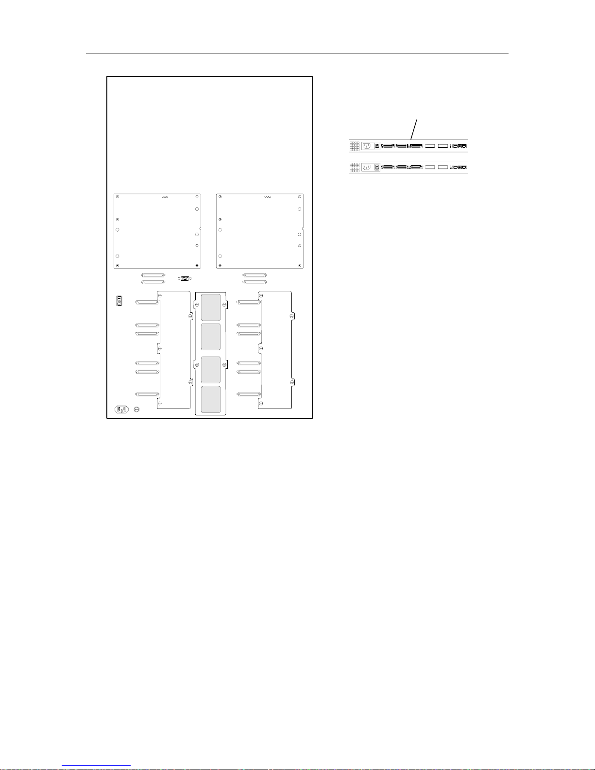
Type B Fibre Channel Options
Figure 3-2 Type B Fibre Channel Option Installed next to a TLS-412xxx Library
501440 Rev. J Product Description 3-3
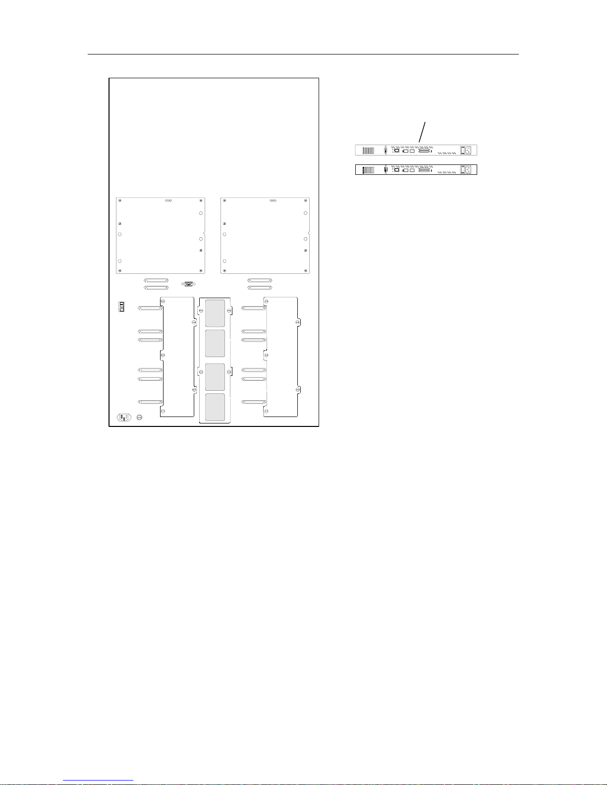
ATTO Fibre Channel Options
Figure 3-3 ATTO Fibre Channel Option Installed next to a TLS-412xxx Library
3-4 501440 Rev. J Product Description

4. FCO Type C Installation
4.1 Fibre Channel Option (FCO) Type C Installation Considerations
4.1.1 Operating Environment
A TLS with the Fibre Channel Option is designed to operate in an ambient environment from 41
from -1000 to +10,000 feet. Moisture must not be allowed to condense inside the system.
o
F to 95oF (5oC to 35oC), 20% to 80% relative humidity, and at altitudes
4.1.2 Ventilation
When selecting a location for the TLS, be sure to provide sufficient space behind the
unit to allow for cable connections. Also, be sure nothing will block the air intake at
the inlet air filters or the top air vent slots.
4.2 FCO Type C Interconnect Cabling
The Fibre Channel Option for TLS-84xx libraries is installed when they are shipped
from the factory. All other models have the Fibre Channel Option shipped separately
from the libraries and require installation in the field. They are attached to the rear of
the TLS, taking the place of the rear service panel. All the bridge/router interconnect
cables are accessed at the rear of the unit.
501440 Rev. J 4-1 FCO Type C Installation
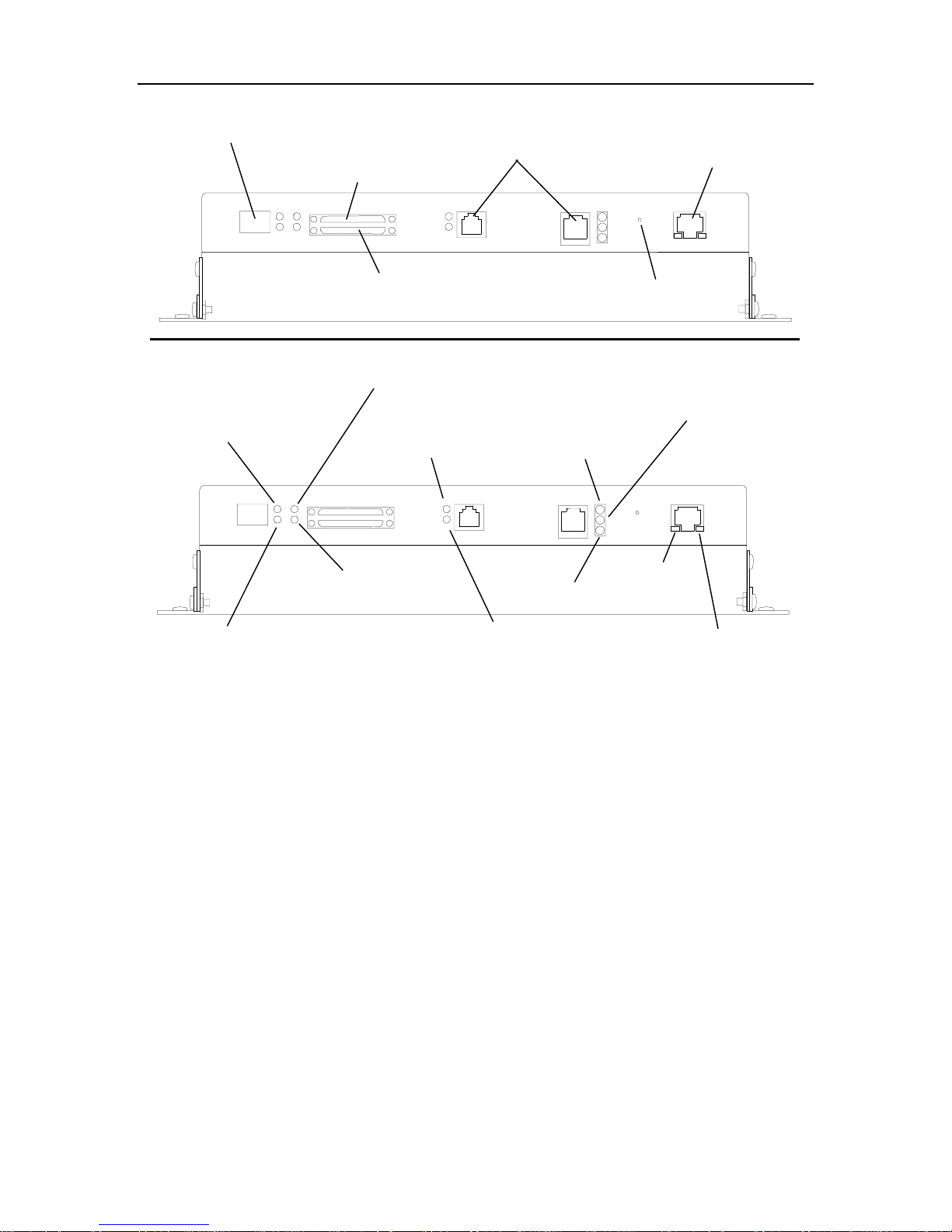
Fibre Channel 0
SCSI Channel 1
Serial Jumper
Connectors
Q-Link 10BaseT
LINK LED
(Fibre Channel)
ACTIVITY CHANNEL 0 LED
ACTIVITY LED
(Fibre Channel)
SCSI Channel 0
ACTIVITY CHANNEL 1 LED
(SCSI)
FAULT LED
(SCSI)
+5V FCO LED
+12V LED
STATUS OK LED
Reset Button
+5V EXEC LED
LINK LED
(Q-Link)
Figure 4-1 Bottom View of the Type C Fibre Channel Bridge/Router (FCO)
ACTIVITY LED
(Q-Link)
The following table briefly describes the components located on the bottom of the
FCO.
FCO Type C Installation 501440 Rev. J 4-2

Component Description
Fibre Channel 0 Small Form Factor Pluggable (SFP) transceiver socket. The receptacle is a 2
Gbit Fibre Channel SFP transceiver.
SCSI Channel 0 and 1 The SCSI Ultra 160 channels used to attach the TLS medium changer and
tape drives.
Serial Jumper Connectors The serial bridge cable provides a serial communication link between the
FCO and the TLS library. This interface is used to configure the FCO.
Reset Button The reset button is used to reset the Q-Link processor.
Q-Link 10 BaseT The Q-Link Ethernet interface connection.
Activity LED
(Fibre Channel)
Link LED
(Fibre Channel)
Activity Channel 0 &1 LEDs
(SCSI)
Fault LED Solid on (red) when a fatal error condition is present. This indicator will be on
Status OK LED Solid on (yellow) when the FCO is operational.
+5V FCO LED Solid on (green) when the FCO +5volt power is present.
+5V EXEC LED Solid on (green) when the Executive PCBA +5volt power is present.
+12V LED Solid on (green) when the Executive PCBA +12volt power is present.
Link LED
(Q-Link)
Activity LED
(Q-Link)
On (green) when the Fibre Channel is active. Off when there is no Fibre
Channel I/O activity.
On (green) when the Fibre Channel link is connected and established.
Off when the Fibre Channel link is disconnected and/or not established.
On (green) when SCSI bus is active or busy.
during power-on diagnostics, and is extinguished after successful completion
of the power-on sequence.
Solid on (green) when the 10BaseT link is connected.
On (yellow) when then 10BaseT link is active or busy.
Table 4-1 Components Located on Bottom of FCO
501440 Rev. J FCO Type C Installation 4-3

A
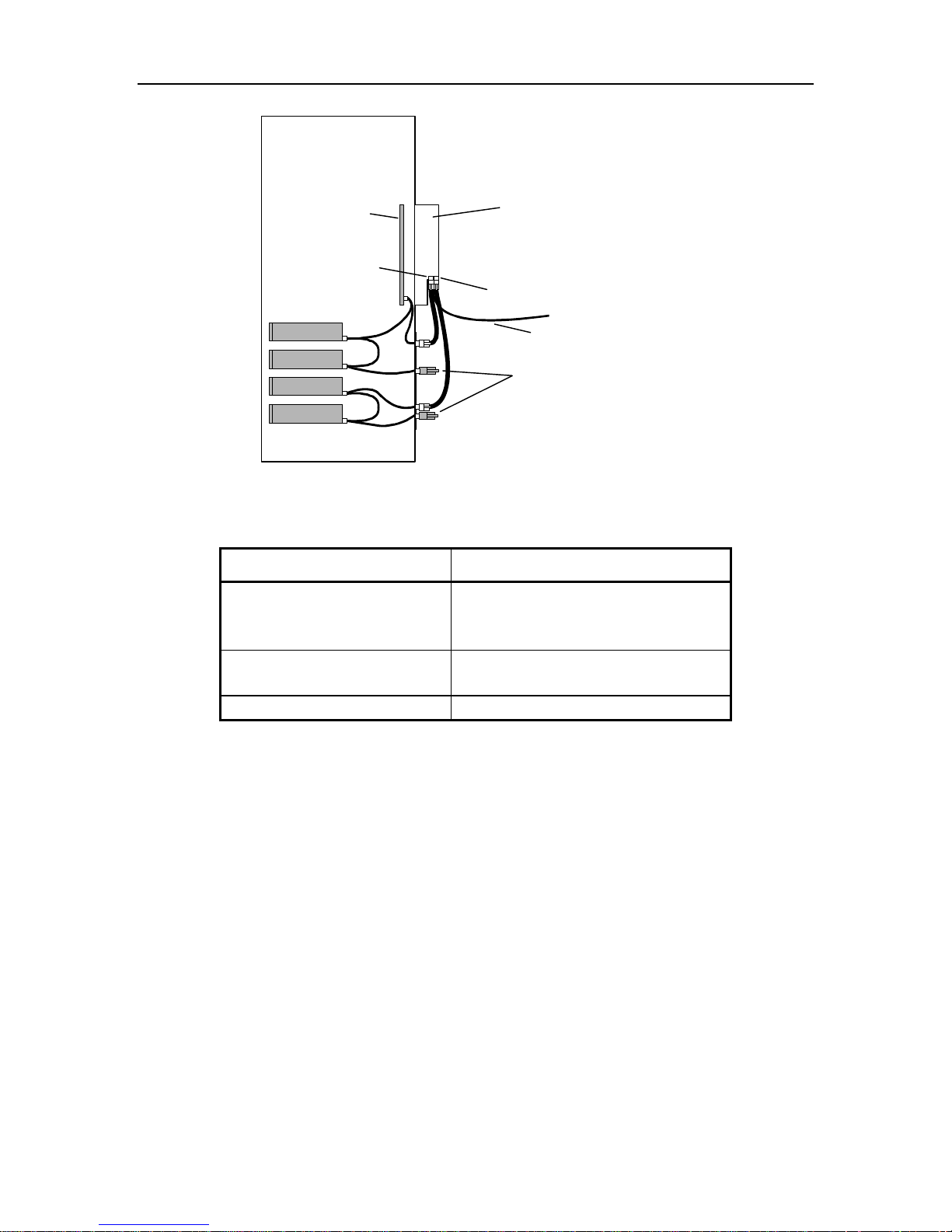
4.3 Cabling for TLS-42xx (using AIT-3 or 5 Tape Drives), TLS-44xx
and TLS-46120 (using AIT-3 Tape Drives)
Note that all TLS models are shipped from the factory without the SCSI interconnect
cables or terminators installed. The following figures and tables represent the preferred cabling for a library with two to six tape drives.
FCO
Executive PCB
SCSI Channel 0
Fibre Channel Cable
Drive 1
Drive 2
To Host or Switch
Terminator
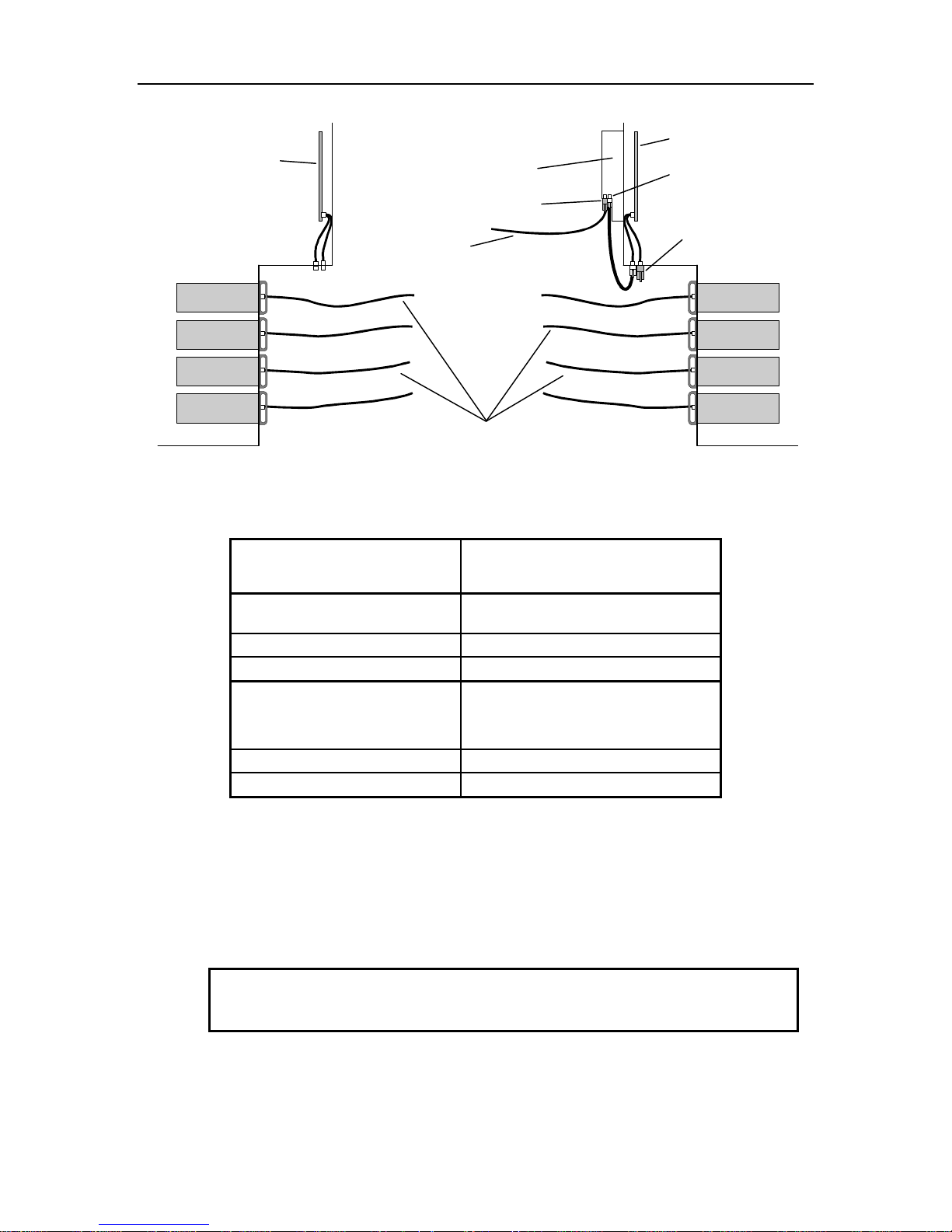
Figure 4-2 TLS-42xx Cabling Diagram
Connectors on Rear of FCO Connectors on Rear of TLS-42xx
FCO: SCSI Channel 0 Medium Changer
Tape Drive 1 (T1)
Tape Drive 2 (T2)
FCO: SCSI Channel 1 None
FCO: Serial Jumper
Table 4-2 Preferred TLS-42xx Fibre Channel Option Cable Connections
FCO Type C Installation 501440 Rev. J 4-4
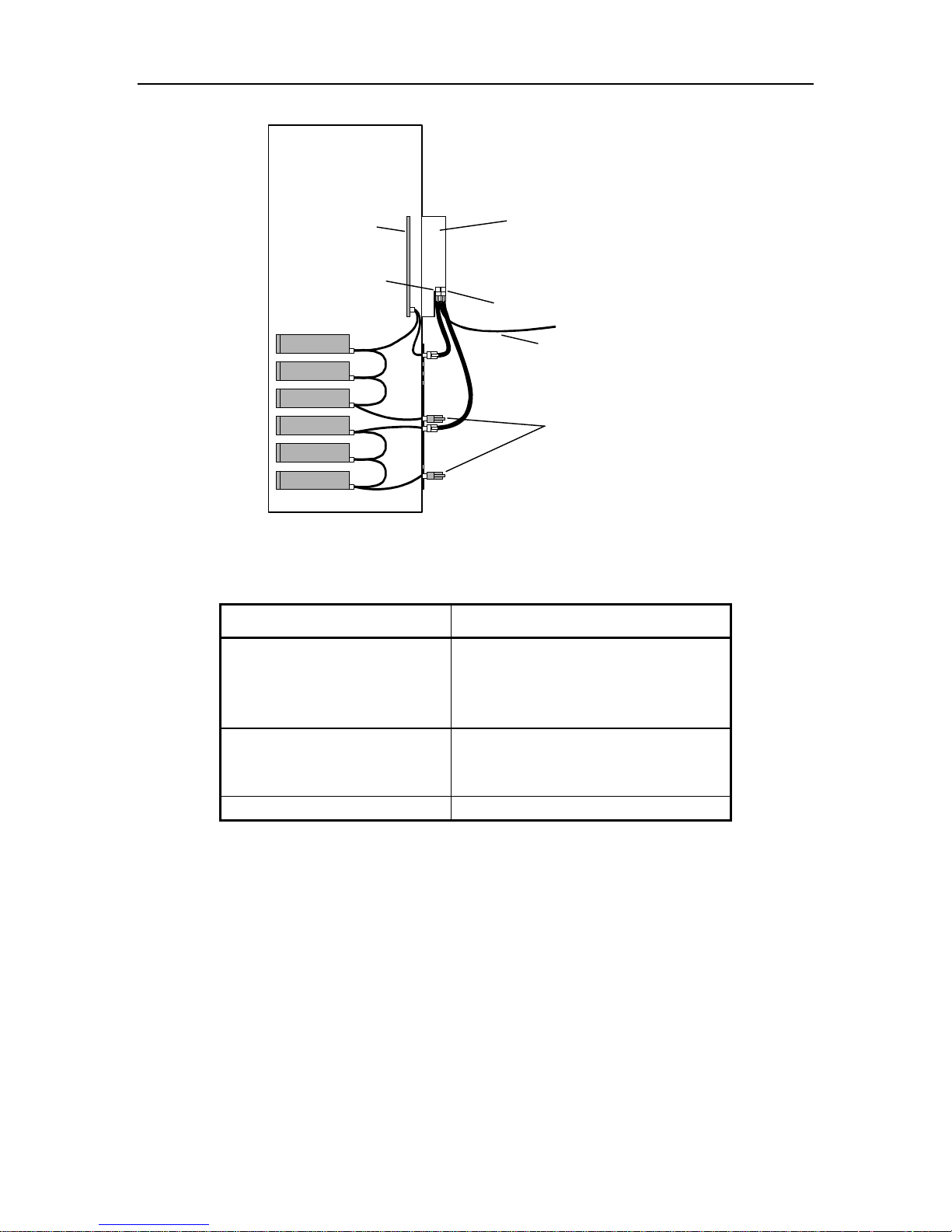
Executive PCBA
SCSI Channel 0
Drive 1
Drive 2
Drive 3
Drive 4
FCO
SCSI Channel 1
Fibre Channel Cable
To Host or Switch
Terminators
Figure 4-3 TLS-44xx Cabling Diagram using AIT-3 Tape Drives
Connectors on Rear of FCO Connectors on Rear of TLS-44xx
FCO: SCSI Channel 0 Medium Changer
Tape Drive 1 (T1)
Tape Drive 2 (T2)
FCO: SCSI Channel 1 Tape Drive 3 (T3)
Tape Drive 4 (T4)
FCO: Serial Jumper
Table 4-3 Preferred TLS-44xx Fibre Channel Option Cable Connections for AIT-3 Tape Drives
501440 Rev. J FCO Type C Installation 4-5
Executive PCBA
SCSI Channel 0
Drive 1
Drive 2
Drive 3
Drive 4
Drive 5
Drive 6
FCO
SCSI Channel 1
Fibre Channel Cable
To Host or Switch
Terminators
Figure 4-4 TLS-46xxx Cabling Diagram using AIT-3 Tape Drives
Connectors on Rear of FCO Connectors on Rear of TLS-46xxx
FCO: SCSI Channel 0 Medium Changer
Tape Drive 1 (T1)
Tape Drive 2 (T2)
Tape Drive 3 (T3)
FCO: SCSI Channel 1 Tape Drive 4 (T4)
Tape Drive 5 (T5)
Tape Drive 6 (T6)
FCO: Serial Jumper
Table 4-4 Preferred TLS-46xxx Fibre Channel Option Cable Connections for AIT-3 Tape Drives
4.4 Cabling for TLS-8000 and 88xxx Libraries
Prior to installing a Fibre Channel Option on TLS-8000 or 88xxx libraries the tape
drive assemblies may need to be installed in the library and the drives will need to be
cabled as shown in this section. Refer to the Installation section in the TLS5000/6000/8000 Installation and Operation Manual (Qualstar document number
501450) for details about tape drive assembly preparation, enabling SCSI termination
power and installation.
FCO Type C Installation 501440 Rev. J 4-6
A
Note that all TLS models are shipped from the factory without the SCSI interconnect
cables or terminators installed.
The following figures and tables represent the preferred cabling for a library with two
to eight tape drives.
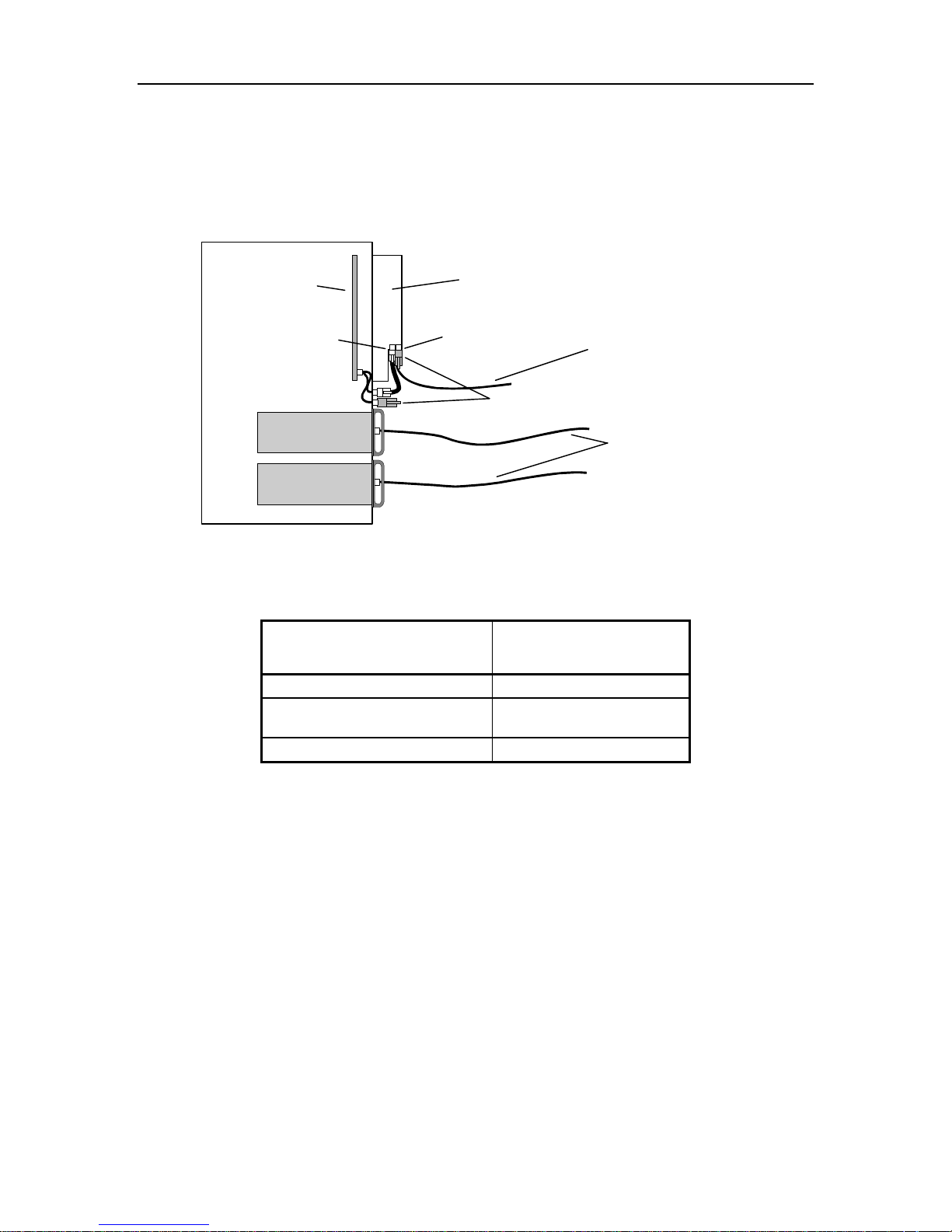
Executive PCB
SCSI Channel 0
Drive 1
Drive 2
Figure 4-5 TLS-82xx Cabling Diagram
Connectors on Rear of FCO Connectors on Rear of
FCO: SCSI Channel 0 Medium Changer
FCO: SCSI Channel 1
(Terminator)
FCO: Serial Jumper
FCO
SCSI Channel 1
Terminator
Fibre Channel Cable
To Host or Switch
Fibre Channel Cables
To Host or Switch
TLS-82xx
Table 4-5 Preferred TLS-82xx Fibre Channel Option Cable Connection
501440 Rev. J FCO Type C Installation 4-7
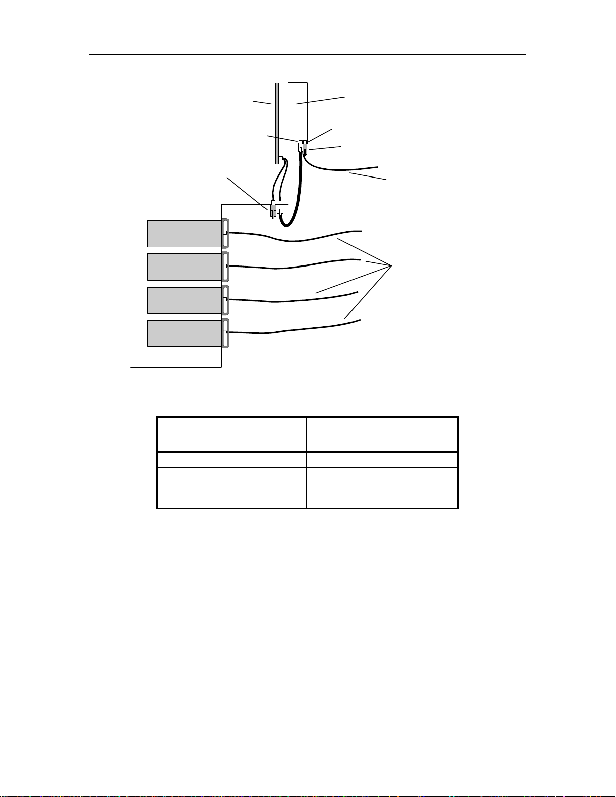
A
Executive PCB
Drive 1
Drive 2
Drive 3
Drive 4
SCSI Channel 0
Terminator
FCO
SCSI Channel 1
Terminator
Fibre Channel Cable
To Host or Switch
Fibre Channel Cables
To Host or Switch
Figure 4-6 TLS-84xx Cabling Diagram
Connectors on Rear of FCO Connectors on Rear of
TLS-84xx
FCO: SCSI Channel 0 Medium Changer
FCO: SCSI Channel 1
(Terminator)
FCO: Serial Jumper
Table 4-6 Preferred TLS-84xx Fibre Channel Option Cable Connections
FCO Type C Installation 501440 Rev. J 4-8
A
A
Executive PCB
Fibre Channel Cable
To Host or Switch
Drive 4
Drive 3
Drive 2
Figure 4-7 TLS-88xxx Cabling Diagram
Connectors on Rear of FCO Connectors on Rear of
FCO
Terminator
Fibre Channel Cables
To Host or Switch
TLS-88xxx Library
Executive PCB
SCSI Channel 0
Terminator
Drive 1
Drive 2
Drive 3
Drive 4 Drive 1
Left FCO: SCSI Channel 0
(Terminator)
Left FCO: SCSI Channel 1
Left FCO: Serial Jumper
Right FCO: SCSI Channel 0 Right Medium Changer
Right FCO: SCSI Channel 1
Right FCO: Serial Jumper
Left Medium Changer
Right Tape Drive 1 (RT1)
Right Tape Drive 2 (RT2)
Table 4-7 Preferred TLS-88xxx Fibre Channel Option Cable Connections
4.5 Installing a Fibre Channel Option
CAUTION
Be sure to turn the library’s power off before installing or removing a Fibre Channel Option.
501440 Rev. J FCO Type C Installation 4-9
4.5.1 Installation
The following steps outline the actions necessary to install a Fibre Channel Option
onto a library.
1. Remove power from the TLS: first turn the power switch off and then remove the
power cord.
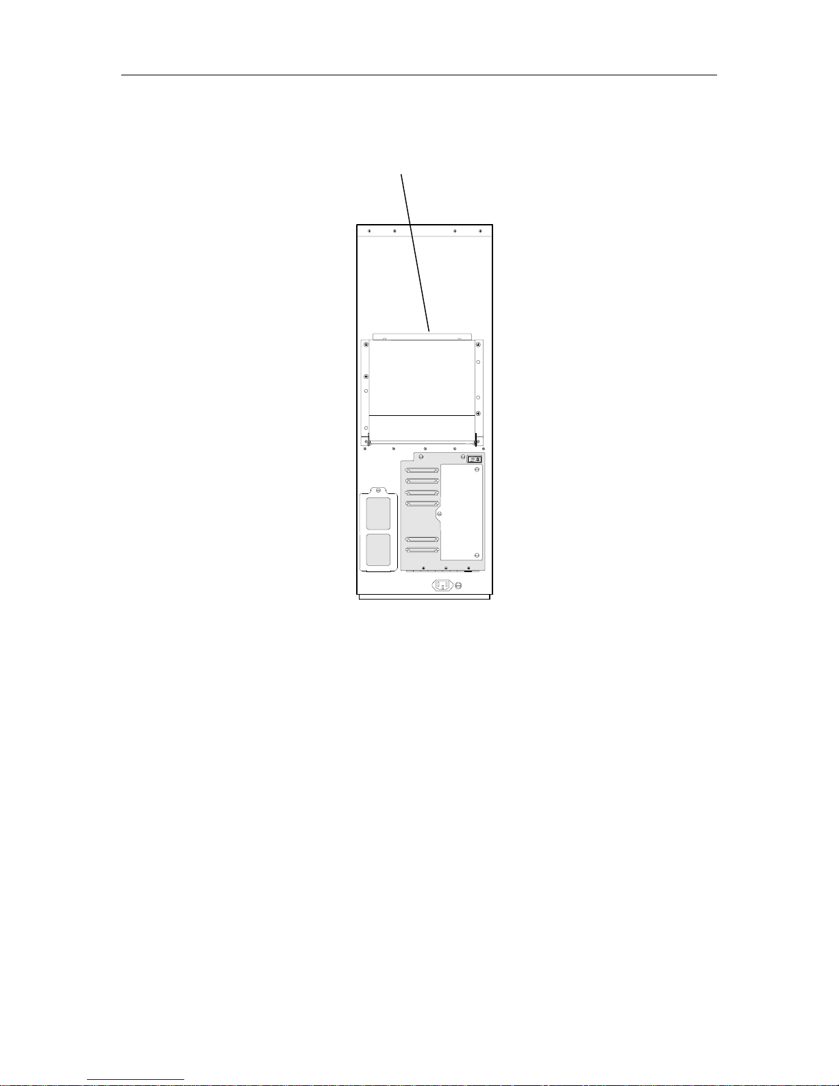
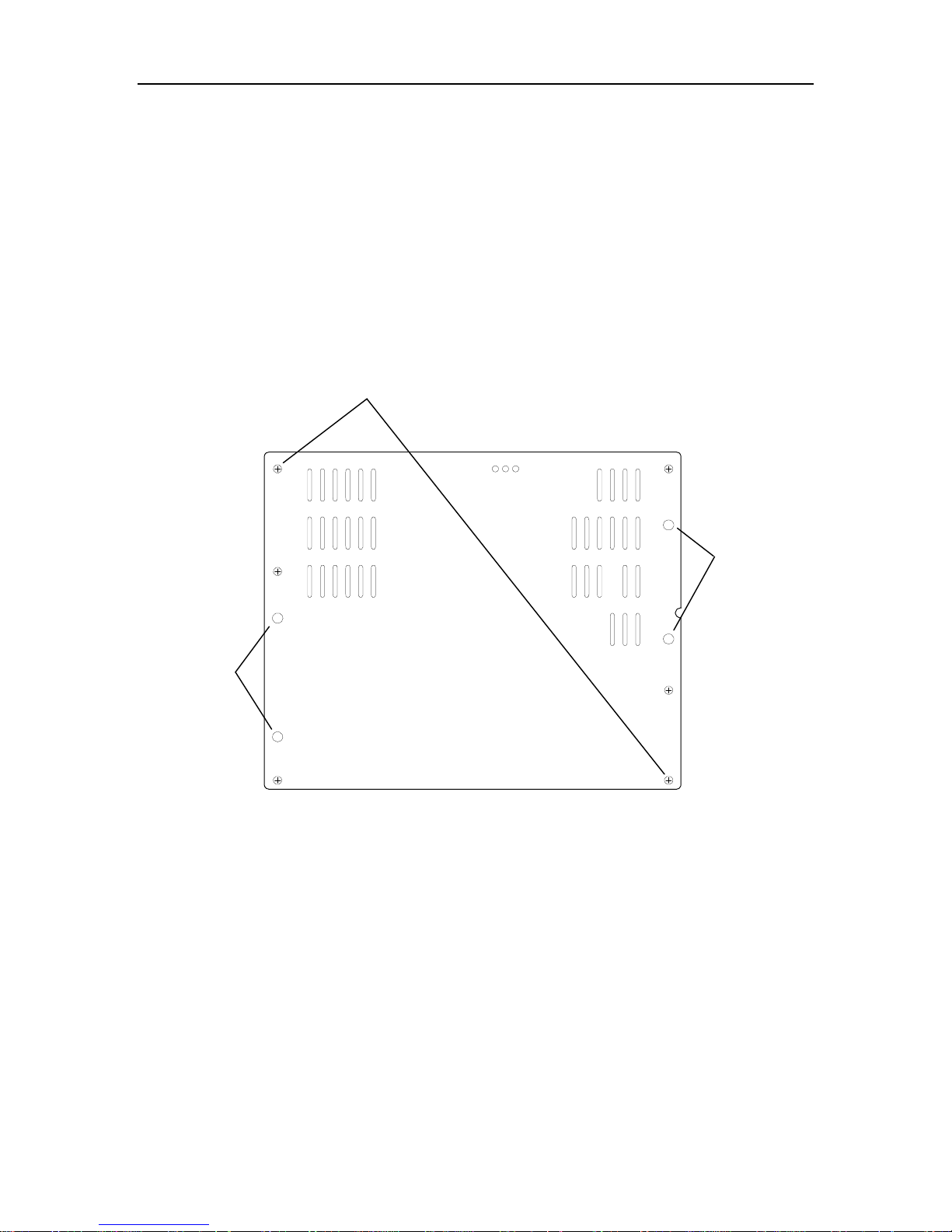
2. Using a Phillips screwdriver remove the six screws securing the service panel on
the rear of the library – refer to Figure 4-8. Depending of the model of library,
the service panel may not have ventilation slots. Care must be taken to not remove the four screws securing the heatsink panels. Save the service panel for
possible future use.
Do not remove
these screws
Figure 4-8 Service Panel
Phillips Screws (6)
Do not remove
these screws
3. Place the lower lip of the FCO inside the bottom edge of the service panel opening and tilt the FCO upwards, making sure that the heatsink panel screws align
with the openings in the FCO. See Figure 4-9. The hinge surfaces should rest flat
against the rear of the library.
4. Using a Phillips screwdriver, secure the FCO to the rear of the library at the
FCO’s two top captive screws. See Figure 4-9.
5. Using two of the screws that were removed with the service panel, attach the
FCO’s two hinges to the rear of the library. See Figure 4-9.
FCO Type C Installation 501440 Rev. J 4-10
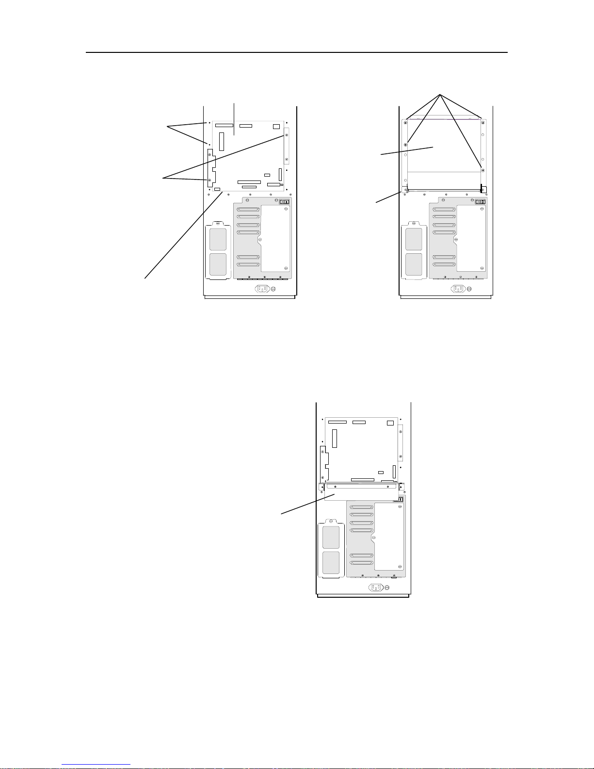
Executive PCBA
Screw Holes (6)
Heatsink Panel
Screws (4)
Bottom Edge of
Service Panel Opening
Figure 4-9 Rear View of TLS
Captive Screws (4)
Fibre Channel
Option
FCO’s
Hinges (2)
6. Loosen the two top captive screws on the FCO that were tightened in step number four. Carefully guide the FCO backwards as it pivots on the hinges and
comes to its open position. See Figure 4-10.
FCO in Open Position
Figure 4-10 Fibre Channel Option in the Open Position
7. Connect the AUXPWR cable to the AUXPWR connector on the Executive PCBA
and to the PWRIN connector on the Fibre Channel Option. See Figure 4-11 and
Figure 4-13.
501440 Rev. J FCO Type C Installation 4-11
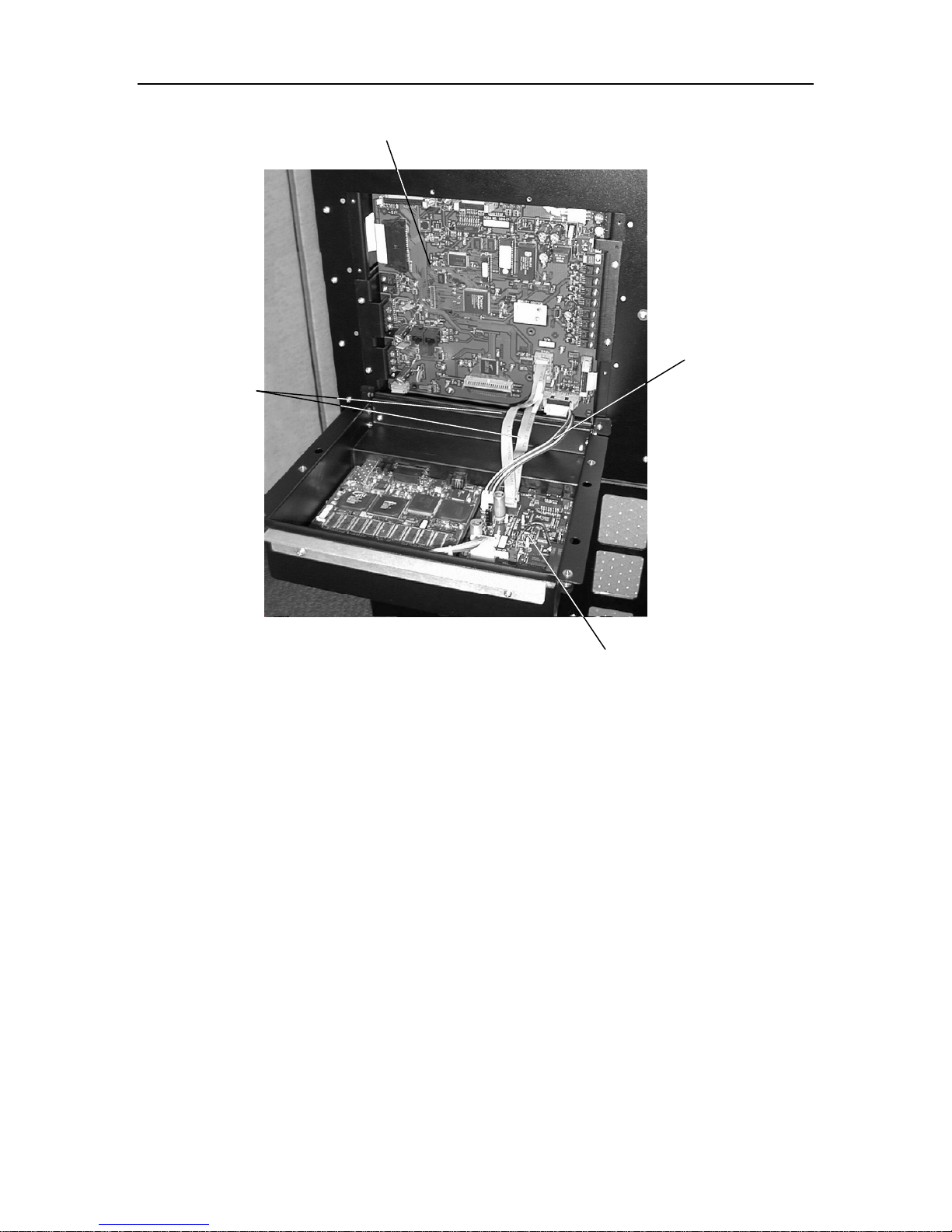
SERIAL
Ribbon Cables
Executive PCBA
AUXPWR Cable
Fibre Channel Option
Figure 4-11 Executive PCBA and Fibre Channel Option (Executive IV PCBA Shown)
8. The FCO’s SERIAL ribbon cable will connect to differently named connectors on
the Executive PCBA depending on which version of Executive PCBA is installed
in the library. Executive III PCBA’s will have part number 501387-printed on
them and Executive IV boards will have part number 501447- on them. Refer to
Figure 4-12 to determine which version of Executive PCBA the FCO is being
connected to.
FCO Type C Installation 501440 Rev. J 4-12
 Loading...