

Qualstar 34XX Series, 34 Series User Manual

The Tape Experts
34XX
User’s Guide
500300 Rev. U

Notice
Information contained in this document is copyrighted by Qualstar
Corporation. It is intended for use by Qualstar's customers and prospective
customers to evaluate, integrate, operate and maintain Qualstar products.
Customers and prospective customers may reproduce this document as
needed for these uses. Reproduction in whole or in part for any other use or
by any other party is prohibited without prior written permission from
Qualstar Corporation.
Every effort has been made to keep the information contained in this
document current and accurate as of the date of publication or revision.
However, no guarantee is given or implied that the document is error-free
or that it is accurate with regard to any specification. Qualstar reserves the
right to modify product designs and specifications without notice.
Qualstar® is a registered trademark of Qualstar Corporation.
Cipher® is a registered trademark of Overland Data.
Pertec® is a registered trademark of DDC Pertec.
IBM® is a registered trademark of International Business Machines,
Incorporated.
QUALSTAR CORPORATION
6709 Independence Avenue
Canoga Park, CA 91303
FAX: (818) 592-0116
Phone: (818) 592-0061
Email: sales@qualstar.com
Web: www.qualstar.com
500300 Rev. U i
CAUTION
References contained in this manual to DIP switch settings, jumper locations,
primary voltages and other options are for reference only. Access to the interior
of this equipment is restricted to dealers and qualified service technicians, and
only in accordance with published service manuals and bulletins.
WARNING
PERSONAL INJURY MAY RESULT IF YOU DO NOT FULLY COMPLY WITH THE
HANDLING, OPERATING, OR SERVICE INSTRUCTIONS FOUND IN A
WARNING PARAGRAPH.
ACHTUNG
ES KÖNNEN PERSONENVERLETZUNGEN AUFTRETEN, WENN SIE DIE
UMGANGS-, BEDIENUNGS- ODER WARTUNGSANWEISUNGEN NICHT
VOLLSTÄNDIG BEFOLGEN, DIE IM ACHTUNGENPARAGRAPHEN BESCHRIEBEN
SIND.
DANGER
EXTREME HAZARD IF YOU DO NOT FULLY COMPLY WITH THE HANDLING,
OPERATING, OR SERVICE INSTRUCTIONS FOUND IN A DANGER PARAGRAPH.
GEFAHR
SIE SIND EXTREMER GEFAHR AUSGESETZT, WENN SIE DIE UMGANGS-,
BEDIENUNGS- ODER WARTUNGSANWEISUNGEN NICHT VOLLSTÄNDIG
BEFOLGEN, DIE IM GEFAHRENPARAGRAPHEN BESCHRIEBEN SIND.
NOTE
SPECIAL ATTENTION to explanatory statements found in a NOTE paragraph will help you avoid
mistakes and/or save time.
ii 500300 Rev. U

Federal Communications Commission Requirements
This equipment has been tested and found to comply with the limits for a Class A
computing device pursuant to Subpart J of Part 15 of FCC Rules, which are designed
to provide reasonable protection against such interference when operated in a
commercial environment. Operation of this equipment in a residential area may
cause unacceptable interference to radio and TV reception, in which case the user at
his own expense will be required to take whatever steps are necessary to correct the
interference.
Patent Notice
The following patents apply to all models of the 3400 Series tape transport:
Pat. No. 4,893,312; Pat. No. 5,014,141
Bescheinigung des Herstellers/Importeurs
Hiermit wird bescheinigt, daß Qualstar Bandgeräte Modelle 3402S, 3402SD, 3404S,
und 3404SD in Übereinstimmung mit den Bestimmungen der Vfg.-1046/1984 funkentstört sind.
Der Deutschen Bundespost wurde das Inverkehrbringen dieses Gerätes angezeigt
und die Berechtigung zur Überprüfung der obengenannten Modelle auf Einhaltung
der Bestimmungen eingeräumt.
English Translation:
This certifies that the Qualstar model 3402S, 3402SD, 3404S and 3404SD tape
drives are RFI-suppressed in accordance with German Postal Regulation 1046/1984.
The marketing and sale of this equipment was reported to the German Postal
Service, along with the authorization to verify the above-mentioned models for
compliance to the regulation.
500300 Rev. U iii

Important — Read This Before Installation
Qualstar Corporation has made every effort to provide quality merchandise.
If the merchandise arrives damaged or has been mishandled, please notify
the delivery company immediately. If the merchandise is defective in any
other way, please follow these instructions.
If this merchandise was purchased from a dealer or other reseller, contact
that dealer or reseller for return instructions.
If this merchandise was purchased directly from Qualstar, please do the
following:
• Treat the merchandise carefully to assure its suitability for return.
• Retain all shipping and packing materials. Returned merchandise must be
shipped to Qualstar in the original packing material and carton. If the original
packing material or carton has been damaged, a new set may be requested.
• Call Qualstar Customer Service at (818) 592-0061 to request a Return
Merchandise Authorization (RMA) number. Returned merchandise will not be
accepted without this number.
• Clearly identify the outside of the carton and the packing list with the RMA
number.
• Return the merchandise, including cables, manuals, software and all related
documents to the Qualstar factory.
iv 500300 Rev. U

Table of Contents
1. Tape Drive Installation................................................................................................. 1-1
1.1 Introduction ..............................................................................................................1-1
1.2 Model identification ..................................................................................................1-1
1.3 Operating Environment............................................................................................1-1
1.4 Unpacking the Tape Drive .......................................................................................1-2
1.5 Tools required for Installation..................................................................................1-3
1.6 Power Requirements.................................................................................................1-3
1.6.1 Power Connections.............................................................................................1-4
1.7 SCSI-2 Interface........................................................................................................1-4
1.7.1 SCSI Bus Description.........................................................................................1-6
1.7.2 SCSI Cables and Connectors .............................................................................1-8
1.7.3 SCSI Bus Termination.......................................................................................1-8
1.7.4 Termination Power ..........................................................................................1-10
1.7.5 Industry Standard Interface (non-SCSI).........................................................1-11
1.8 Rack Mount Installation.........................................................................................1-12
2. Controls and Indicators................................................................................................ 2-1
2.1 Front Control Panels ................................................................................................2-1
2.1.1 Power Switch .....................................................................................................2-1
2.1.2 Push-button Switches ........................................................................................2-1
2.2 Front Panel Indicators..............................................................................................2-2
2.3 Liquid Crystal Display..............................................................................................2-3
2.3.1 Display Line One ...............................................................................................2-4
2.3.2 Display Line Two ...............................................................................................2-5
3. Operating Instructions ................................................................................................. 3-1
3.1 Applying Power.........................................................................................................3-1
3.2 Power-Up Self Diagnostic Tests ...............................................................................3-2
3.3 Loading a Tape .........................................................................................................3-3
3.3.1 Load Sequence ...................................................................................................3-5
3.3.2 Aborting a Load Sequence .................................................................................3-6
3.3.3 Load Sequence Exception Conditions................................................................3-6
3.4 Rewinding and Unloading the Tape.........................................................................3-6
3.4.1 Tape Not at BOT................................................................................................3-6
3.4.2 Tape at BOT.......................................................................................................3-7
3.4.3 Manually Unlocking the Supply Hub................................................................3-7
3.5 Changing Densities...................................................................................................3-7
3.6 Automatic Density Selection Feature (ADS)............................................................3-8
3.6.1 Density Definitions ............................................................................................3-8
500300 Rev. U v

3.6.2 Density Modes..................................................................................................3-10
3.7 Abnormal Conditions ..............................................................................................3-12
3.7.1 The Tape Will Not Load...................................................................................3-12
3.7.2 An Out-Of -Tape-Stop Occurs..........................................................................3-12
3.7.3 The Tape Comes Off the Supply Reel ..............................................................3-12
3.7.4 A Power Failure Occurs...................................................................................3-13
3.7.5 A Tape Runaway Condition Occurs.................................................................3-13
3.8 Aborting Online Operations from the Front Panel ................................................3-14
4. Menu Operations............................................................................................................ 4-1
4.1 Menu System Description.........................................................................................4-1
4.1.1 Menu Hierarchy.................................................................................................4-1
4.1.2 Accessing the Menu Mode .................................................................................4-2
4.1.3 Accessing the Demonstration Function.............................................................4-2
4.2 Reset Head Clean Function ......................................................................................4-2
4.3 Drive Configuration Menu .......................................................................................4-3
4.3.1 Using the Drive Configuration menu ................................................................4-3
4.3.2 Drive Configuration Menu Parameters.............................................................4-5
4.4 Manual Threading Function ..................................................................................4-12
4.5 Maintenance Menu.................................................................................................4-12
4.5.1 Using the Maintenance Menu .........................................................................4-14
4.5.2 Default Configuration Function ......................................................................4-14
4.5.3 Default SCSI Configuration Function .............................................................4-14
4.5.4 SCSI Enable Function......................................................................................4-14
4.5.5 Display Firmware Sub-Menu ..........................................................................4-15
4.5.6 Prepare Media Sub-Menu................................................................................4-15
4.5.7 Demonstration Function..................................................................................4-17
4.5.8 Diagnostics Sub-Menu .....................................................................................4-17
4.5.9 Service Sub-Menu ............................................................................................4-22
5. SCSI Configuration........................................................................................................ 5-1
5.1 SCSI Configuration Menu ........................................................................................5-1
5.1.1 SCSI Device ID (Default = 5).............................................................................5-2
5.1.2 SCSI LUN (Default = 0).....................................................................................5-2
5.1.3 SCSI Parity (Default = Off)................................................................................5-2
5.1.4 SCSI Sync (Default = On) ..................................................................................5-2
5.1.5 Space (Default = Normal) ..................................................................................5-2
5.1.6 Unload (Default = Normal) ................................................................................5-3
5.1.7 Write CER (Default = Error) .............................................................................5-3
5.1.8 Write EOT (Default = Write) .............................................................................5-4
5.1.9 Write HER (Default = Report) ...........................................................................5-4
5.1.10 Write Retrys (Default = 13) ...............................................................................5-5
vi 500300 Rev. U

5.1.11 800 Mask WP .....................................................................................................5-5
5.1.12 Block Length (Default = 2).................................................................................5-5
5.1.13 Buffer (Default = Normal)..................................................................................5-6
5.1.14 Busy (Default = Not Ready)...............................................................................5-6
5.1.15 Discon (Default = YES) ......................................................................................5-6
5.1.16 Early EOT (Default = Normal) ..........................................................................5-6
5.1.17 EOM On Read (Default = No)............................................................................5-7
5.1.18 INQUIRY Data File ...........................................................................................5-7
5.1.19 Lng Blk (Default = Stop)..................................................................................5-10
5.1.20 Model (No default) ...........................................................................................5-10
5.1.21 NRZI (Default = No LRC/CRC)........................................................................5-11
5.1.22 Read Bad Data (Default = Yes)........................................................................5-11
5.1.23 Read EOT Stop (Default = No).........................................................................5-11
5.1.24 Read Ahead (Default = 2 FMK) .......................................................................5-11
5.1.25 Read CER (Default = Ignore)...........................................................................5-12
5.1.26 Read HER (Default = Report) ..........................................................................5-12
5.1.27 Read Retrys......................................................................................................5-12
5.1.28 Residue (Default = Normal) .............................................................................5-13
5.1.29 Rewrite CER (Default = Yes) ...........................................................................5-13
5.2 Special Drive Configuration Menu Requirements for SCSI Drives.......................5-14
5.2.1 LOL Enable......................................................................................................5-14
5.2.2 Command Disp.................................................................................................5-14
5.2.3 HER on Blank ..................................................................................................5-14
5.2.4 Drive Address...................................................................................................5-14
5.2.5 FEN ..................................................................................................................5-14
5.2.6 Density CMD....................................................................................................5-14
5.2.7 WRT Parity ......................................................................................................5-15
5.3 SCSI Error Messages and Codes ............................................................................5-15
6. Preventative Maintenance ........................................................................................... 6-1
6.1 Purpose .....................................................................................................................6-1
6.2 Frequency .................................................................................................................6-1
6.3 Tape Path Cleaning Procedure.................................................................................6-2
6.4 Using 1-mil Tape.......................................................................................................6-4
6.5 Data Specifications ...................................................................................................6-5
6.5.1 Data Formats and Tape Speeds.........................................................................6-5
6.5.2 Data Transfer Rate ............................................................................................6-5
6.5.3 Media Requirements..........................................................................................6-6
6.6 Data Capacity ...........................................................................................................6-6
6.6.1 Data Capacity Tables.........................................................................................6-7
7. Errors and Operational Failures ................................................................................ 7-1
500300 Rev. U vii

7.1 General......................................................................................................................7-1
7.2 Error Messages .........................................................................................................7-1
7.2.1 Non-Terminal Errors .........................................................................................7-1
7.2.2 Terminal Errors .................................................................................................7-1
7.2.3 Miscellaneous Messages ....................................................................................7-3
7.2.4 SCSI Error Messages .........................................................................................7-3
8. AC Power Configuration .............................................................................................. 8-1
8.1 Tools Required to Change AC Power Configuration ................................................8-2
8.2 Configuring the Drive for Available Power..............................................................8-2
viii 500300 Rev. U
1. Tape Drive Installation
1.1 Introduction
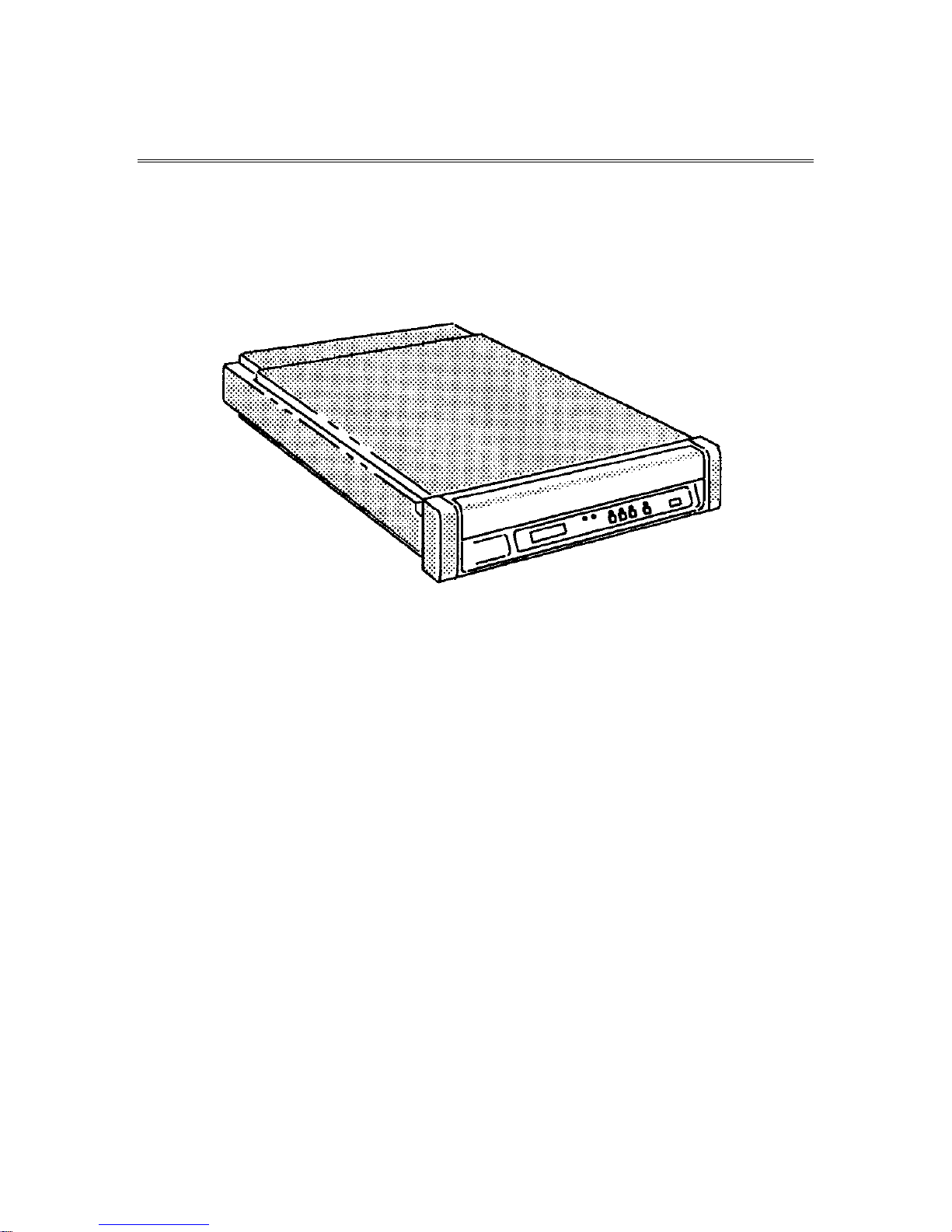
This guide provides installation instructions and techniques for operating the
Qualstar Model 34XX Series tape drive.
Figure 1-1 The Qualstar 34XX Series Tape Drive
1.2 Model identification
Figure 1-2 identifies the various 34XX models. This User's Guide applies to all
models; the installation and operation of the different models is basically the same.
Differences among models are noted where required; from an operator's point of
view, all models function similarly.
1.3 Operating Environment
The tape drive is designed to operate in an environment between 40° F to 104° F
(4.4° C to 40° C), 20% to 85% relative humidity, and at altitudes from 0 to +8000
feet. Moisture must not be allowed to condense inside the drive or in the tape path
area. Note that the humidity and temperature specifications of the drive exceed that
of most media.
500300 Rev. U Tape Drive Installation 1-1
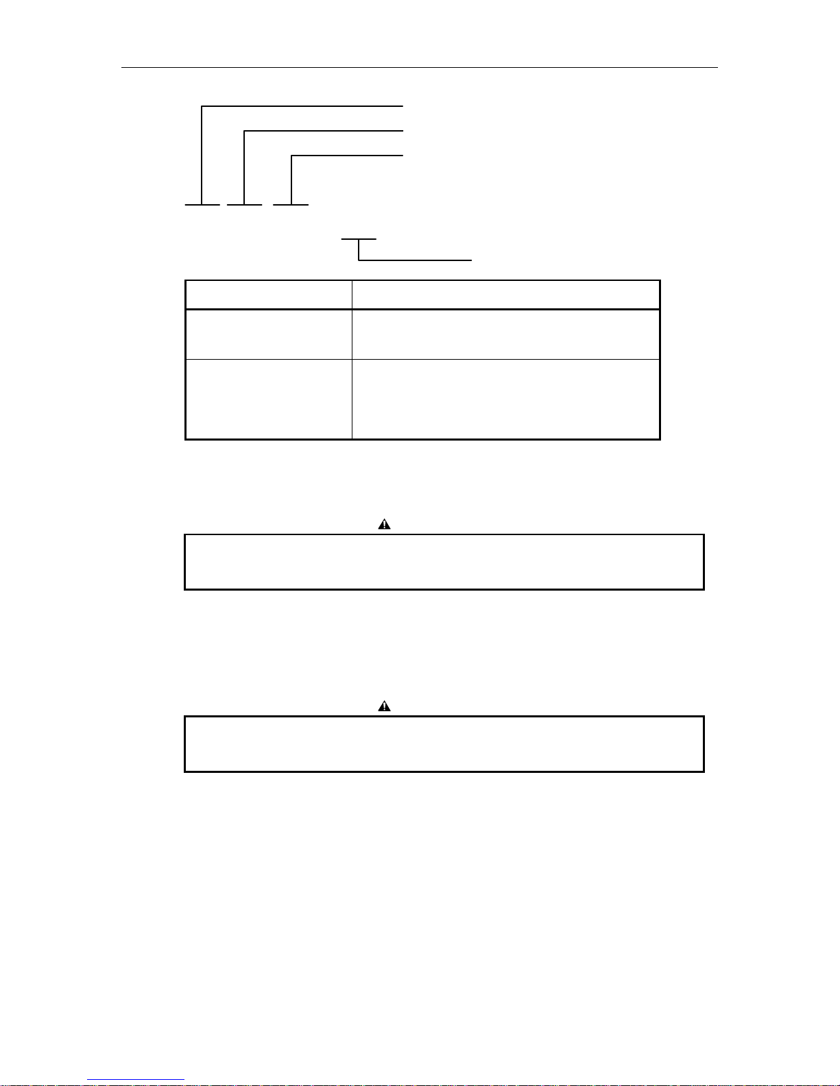
3 4 X X X X – X X
Basic Series
See Table Below
Interface Options
Blank = Industry Standard Interface
S = SCSI-2 Single-Ended
SD = SCSI-2 Differential (HVD)
Special Features
Configuration Supported Densities
Rack Mount Desktop 800
125 IPS
3402 3404 X X
3410 3412 X X X X
3413 3414 X X
3416 3418 X X X X X
Figure 1-2 Model Number Identification
To insure adequate airflow through the drive, the fan at the rear of the drive
must not be blocked.
1.4 Unpacking the Tape Drive
1600
125 IPS
CAUTION
CAUTION
3200
62.5
IPS
6250
125 IPS
6250
62.5
IPS
The tape drive weighs about 60 pounds and must be lifted out of the box by two
persons. Use caution in lifting.
The tape drive is shipped in a specially designed double-walled carton with energyabsorbing end caps and contains the following items:
• Tape Drive
• Power Cord
• User’s Guide (this document)
Remove the drive together with its end-caps from the carton and place it on a table.
Then remove the end-caps and the polyethylene bag. Remove all other materials
1-2 Tape Drive Installation 500300 Rev. U

from the carton and store the end-caps and bag in the carton. Store the carton for
possible future transportation.
1.5 Tools required for Installation
A #2 Phillips screwdriver may be required to install the drive.
1.6 Power Requirements
The tape drive requires 100, 120, 220, or 240 volts AC, +10%/-15%, at 48 to 62 Hertz
primary power. The “worst case” power consumption is 225 watts. See chapter 8 to
change the selected voltage.
Figure 1-3 Location of Voltage Label
IF THE LINE VOLTAGE DIFFERS FROM THAT SPECIFIED ON THE VOLTAGE
LABEL, DO NOT APPLY POWER. THE POWER TRANSFORMER SELECTOR
SWITCHES AND FUSE MUST FIRST BE CHANGED BY A QUALIFIED SERVICE
PERSON TO MATCH THE LINE VOLTAGE. REFER TO CHAPTER 8.
WENN DIE LEITUNGSSPANNUNG SICH VON DER AUF DEM
SPANNUNGSAUFKLEBER ANGEGEBENEN SPANNUNG UNTERSCHEIDET, KEINE
SPANNUNG ANLEGEN. DIE LEISTUNGSTRANSFORMATOR-WAHLSCHALTER
UND SICHERUNG MÜSSEN ZUERST VON EINEM WARTUNGSFACHMANN
AUSGEWECHSELT WERDEN, DAMIT SIE ZUR LEITUNGSSPANNUNG PASSEN.
SIEHE KAPITEL 8.
WARNING
ACHTUNG
500300 Rev. U Tape Drive Installation 1-3

1.6.1 Power Connections
The power connection to the drive is by means of a detachable power cord that
complies with the following specifications. There should be a minimum of 1.7-inches
clearance from the rear of the drive for the power connector.
• 100/120 volt applications - U.L. listed and CSA certified three conductor,
18 AWG, SVT vinyl jacketed cord. One end is terminated with an IEC 320, C13
style connector (CEE-22 standard sheet VI). The other end is terminated with
plug type NEMA 5-15P.
• 220/240 volt applications - U.L. listed and CSA certified three conductor,
18 AWG, SVT vinyl jacketed cord. One end is terminated with an IEC 320, C13
style connector (CEE-22 standard sheet VI). The other end is terminated with
the standard European plug type CEE 7/VII.
The following statement is included for compliance with German safety regulations:
Die Verbindung zür Steckdose sollte möglich kurz sein, und die Steckdose sollte frei
zugänglich bleiben.
(English translation: The connection to the power receptacle should be as short as
possible, and the receptacle should be readily accessible.)
1.7 SCSI-2 Interface
If your tape drive model number contains an “S” or “SD”, you have a SCSI (Small
Computer Systems Interface) tape drive and should read this section for important
information regarding the installation of the interface. If your tape drive has an
Industry Standard Interface (Pertec), you may skip this section. There are two types
of SCSI interfaces available:
• Single-Ended version – identified by an “S” suffix on the model number
• Differential version – identified by an “SD” suffix on the model number
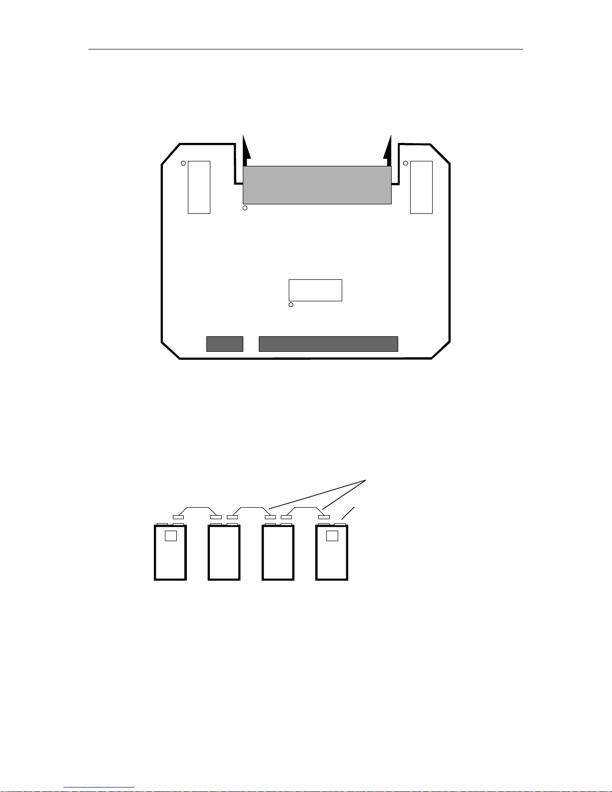
The single-ended SCSI-2 interface is provided by the 500567 board (see Figure 1-4)
which features a one-megabyte intelligent data buffer that increases the data
throughput by helping to keep the tape streaming. The buffer also allows data to
flow to and from the host interface at burst rates over and above the basic data
transfer rate (density times tape speed).
The differential SCSI-2 interface is obtained by adding a 500467 Differential
Adapter board (see Figure 1-5) to the 500567 board. The SCSI connectors remain the
same for both styles of interface.
A description of SCSI-2 is beyond the scope of this guide; however, an explanation of
the physical configuration of the SCSI bus is provided to help you understand the
principles of drive installation, bus termination, and address (device ID) selection.
1-4 Tape Drive Installation 500300 Rev. U
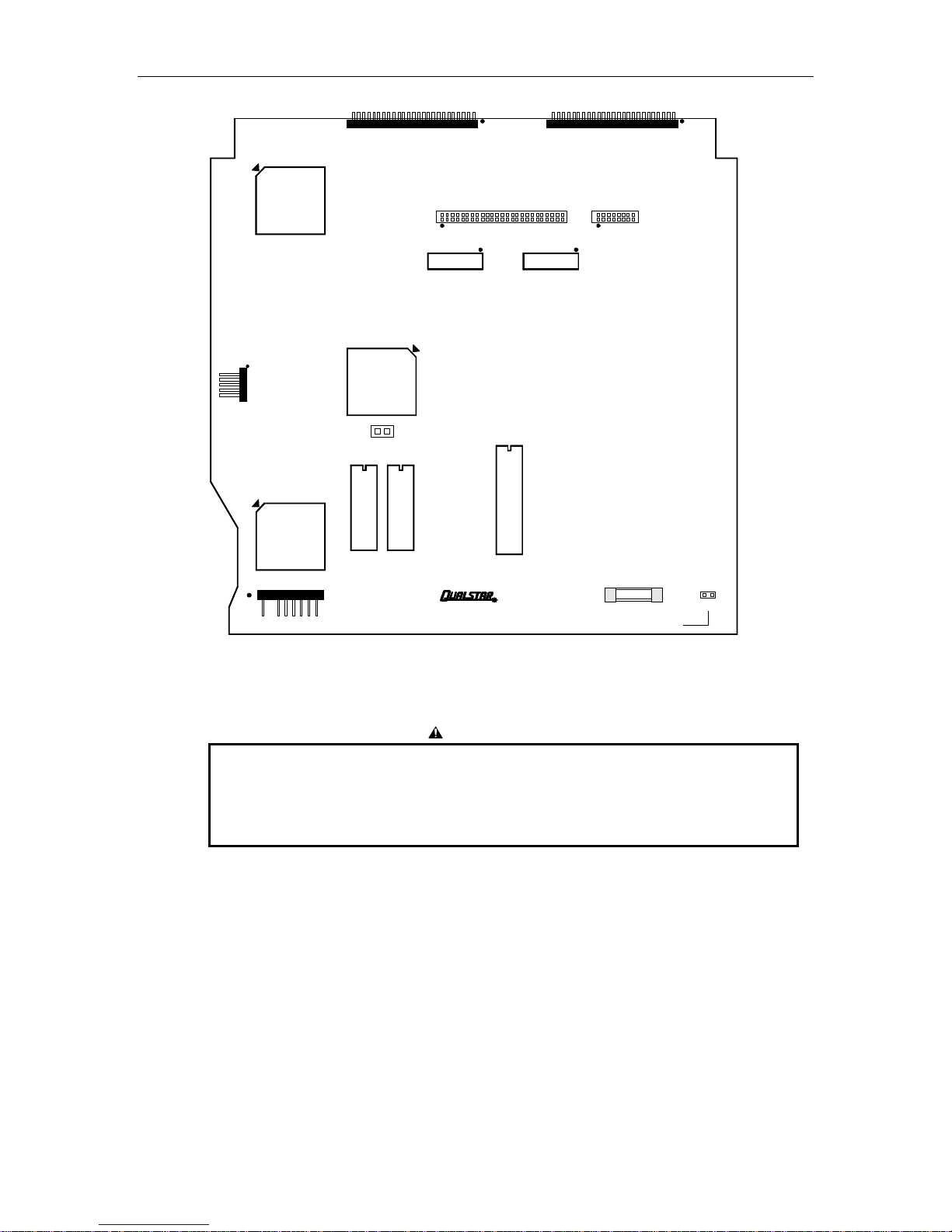
U1
TAPE DRIVE INTERFACE CONNECTORS
J71
SCSI CONNECTOR
J72
J75
RN4
SCSI TERMINATORS
WREX
CONNECTOR
U14
J73
SCSI
CTLR
U21
CPU
U25
RESET
U24
EPROM
POWER
J74
CONNECTOR
PCBA 500567-
PCB500566-01-3 REV B
Figure 1-4 SCSI Single-Ended PCBA Layout – 500567 PCBA
J76
RN3
FUSE
F11ACP1
SCSI TERMINATION POWER
250V
VTERM
CAUTION
The single-ended and differential interfaces are electrically different. A device
with a differential SCSI interface will not operate if connected to a single-ended
SCSI bus. Before connecting any SCSI device to the SCSI bus, insure that the
interface types are the same.
500300 Rev. U Tape Drive Installation 1-5
J86
RN1
RN2
Figure 1-5 SCSI Differential Adapter PCBA
1.7.1 SCSI Bus Description
A SCSI system consists of two or more devices connected together by a multi-line
cable, commonly referred to as the SCSI bus.
RN3
PCBA 5000467-
J85
SCSI Devices (locations on cable are
independent of SCSI ID assignments)
T T
Multiple SCSI Cables
An external terminator may
be installed here in place of
the internal terminator.
Figure 1-6 SCSI Cable Configurations
SCSI devices are usually some type of computer peripheral, such as a printer, a tape
or disk drive, and also a host computer. In the majority of systems, at least one of
the devices is the host itself, with the other devices are peripherals.
The following rules apply to the SCSI bus and its attached devices:
• Up to eight SCSI devices may be connected to one SCSI bus;
1-6 Tape Drive Installation 500300 Rev. U

• The bus must have at least two devices connected to it;
• The device addresses (SCSI ID) range from 0 through 7;
• A device's priority on the bus is determined by its address, with SCSI ID 7 being
the highest priority;
• Each device must have its own, unique SCSI ID;
• The physical location of a device on the bus has nothing to do with the priority
or addressing of that device;
• The total length of the cable, or series of cables, must not exceed six meters
(single-ended configuration) or 25 meters (differential configuration) as
measured from one end to the other.
In most systems, the host computer itself is one of the SCSI devices. This is usually
done using a host adapter, a board that resides within the host and that has one
SCSI connector to the outside world. Device ID 7 is normally reserved for the host
adapter to insure that the host has the highest priority among the other SCSI
devices. Disk drives containing system, application, and data files normally have the
next priority and are assigned a device ID of 5 or 6, while tape drives, printers, and
other low priority devices have correspondingly lower ID numbers.
500300 Rev. U Tape Drive Installation 1-7
1.7.2 SCSI Cables and Connectors
Two identical drive connectors, wired in parallel at the rear of the drive, provide a
connection point to the SCSI bus. Because both drive connectors are wired in
parallel, you may use either one as an input or output, or for an external SCSI bus
terminator. The following drive connectors are supported:
• SCSI Alternative 1 - This is a 50-pin male rectangular, polarized connector,
T&B P/N 622-50FM or equivalent. This connector is flush-mounted against the
inside of the rear panel and has no locking provisions. Plug the cable connector
into either drive connector;
• SCSI Alternative 2 - This is a 50-pin female “Type D” polarized connector,
AMP P/N 1-499977-0 or equivalent. It can be identified by its two rows of pin
receptacles and by the built-in locking tabs at each end.
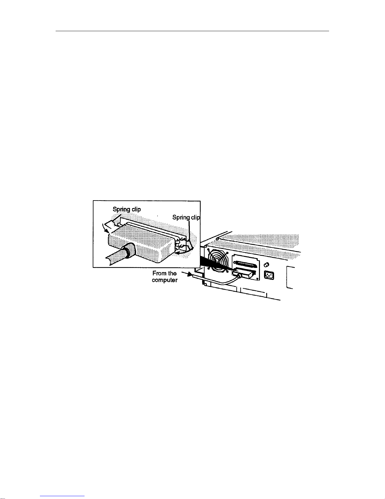
Plug the cable connector into either drive connector and secure it with the two
locking tabs as shown in Figure 1-7.
Figure 1-7 SCSI Cable Configurations
• Sun Systems Connector - This is a 50-pin female “Type D” polarized
connector, AMP P/N 746789-1 or equivalent. It can be identified by its three
rows of pin receptacles and by the screw-type locks at each end.
Plug the cable connector into either drive connector and secure it with the two
locking screws.
1.7.3 SCSI Bus Termination
The SCSI terminators can be located either internally on the SCSI PCBA, or
externally using a customer-supplied terminator plug. Power for either configuration
is supplied by a dedicated termination power line on the SCSI bus; this line may be
powered by the tape drive, as explained in Section 1.7.4, by another device (or
devices) on the SCSI bus, or by both.
1-8 Tape Drive Installation 500300 Rev. U
While any number of devices may supply termination power, only two devices, including the
host adapter, may be terminated on a SCSI bus. If the tape drive is not physically located at the
end of the SCSI bus, you must remove all internal and external terminators from that drive.
1.7.3.1 Internal Terminators
Internal passive termination is supplied by terminators that are installed in sockets
at locations RN3 and RN4 on the single-ended SCSI board, or at locations RN1, RN2,
RN3 on the optional Differential Adapter. The terminator locations are shown in
Figure 1-4 and Figure 1-5. SCSI tape drives are shipped with the internal SCSI
terminators installed.
If the drive is connected to one physical end of the SCSI bus and if internal
termination is desired, terminators RN3 and RN4 (RN1, RN2, and RN3 if using the
differential version) must be installed. The terminators must be removed from all
other devices on the SCSI bus except the device that is physically connected to the
other end of the bus.
1.7.3.2 External Terminators
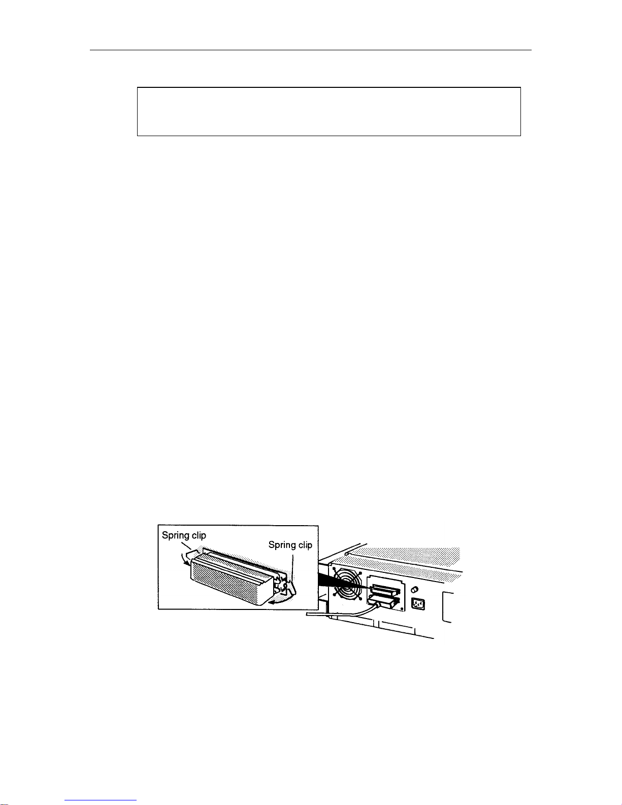
You may install an external terminator in the unused SCSI connector at the rear of
the drive as shown in Figure 1-8. If you do, you must remove the internal
terminators at locations RN3 and RN4 (RN1, RN2, and RN3 if using the differential
version). The terminator locations are shown in Figure 1-4 and Figure 1-5. In no
event should both internal and external terminators be installed.
NOTE
1.7.3.3 Active Termination
If you are connecting your tape drive to the end of a SCSI cable that has an active
type of terminator installed at the other end, you will need to remove the internal
terminators and install an active terminator at the unused SCSI port on the tape
drive. You may purchase active terminators from Qualstar.
Figure 1-8 Connecting the SCSI Cable to the Tape Drive (SCSI Alternative 2 shown)
500300 Rev. U Tape Drive Installation 1-9
1.7.4 Termination Power
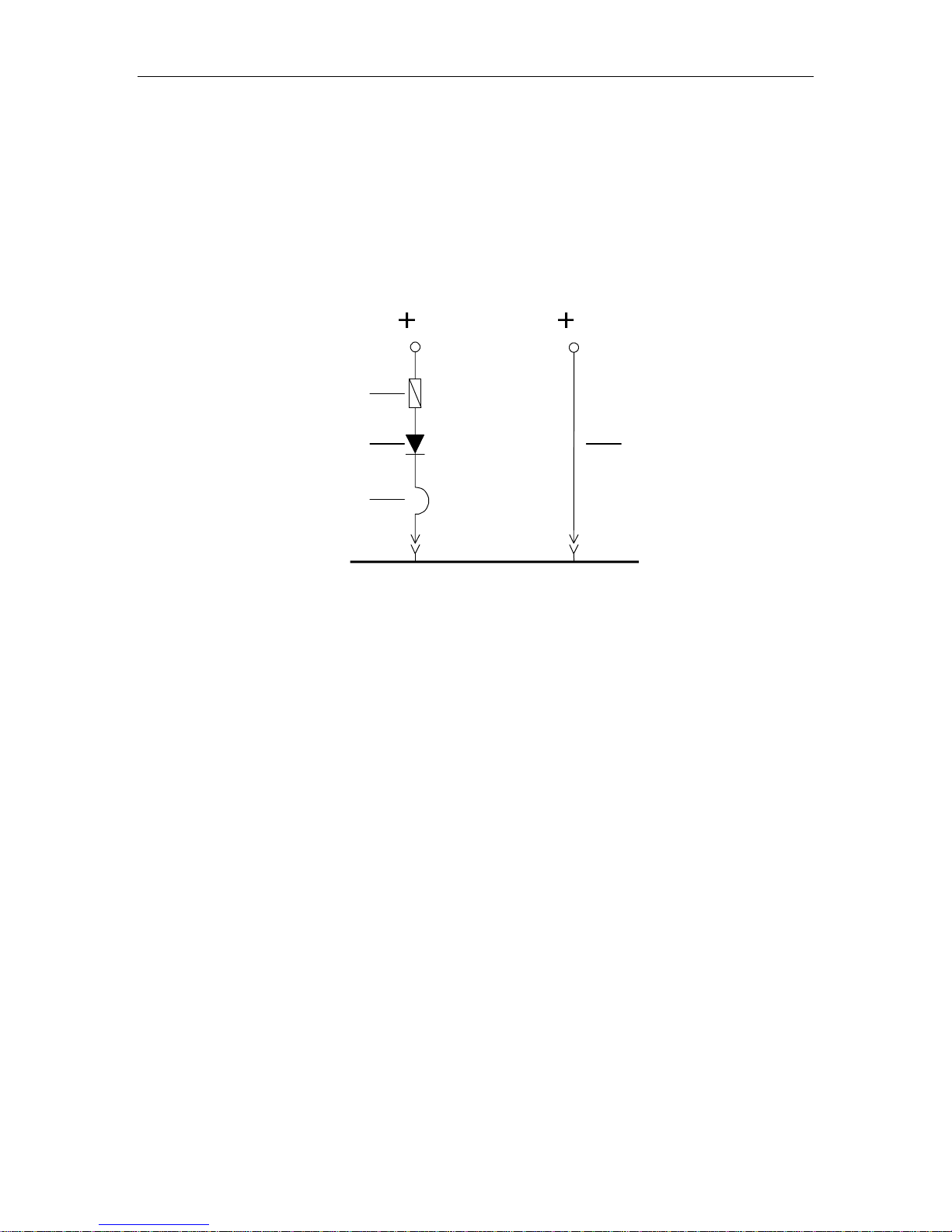
The SCSI PCBA is capable of supplying +5 volts termination voltage to the SCSI
bus. This +5 volts is fed to the SCSI bus TERMPWR line through a circuit protector,
a blocking diode and the jumper VTERM as shown in Figure 1-9. TERMPWR is
connected to both the internal and external terminators in the drive. When SCSI
operation is enabled, the termination power is periodically monitored and if missing,
the front panel will display NO SCSI TERM-V.
QUALSTAR
TAPE DRIVE
Circuit Protector
(current limiter)
Blocking Diode
W1 or VTERM Jumper
TERMPWR on SCSI Bus
Figure 1-9 Diagram of SCSI Termination Power
1.7.4.1 Circuit Protector
A solid state circuit protector and a blocking diode protect the tape drive from
excessive current draw due to an overload on the SCSI bus TERMPWR line. The
circuit protector is connected in series with VTERM between the board’s termination
voltage and the termination voltage line on the SCSI bus. If the current through the
circuit protector is excessive, the protector will open and remain open until the
overload condition is removed. On earlier units, the circuit protector consisted of a
one-ampere fuse F4 (Qualstar P/N 626-0014-3).
5 5
ANOTHER
SCSI DEVICE
(No Blocking Diode)
1.7.4.2 VTERM Jumper
Your tape drive is shipped from the factory with the VTERM jumper installed, and
Qualstar recommends that you do not remove it. If you remove VTERM, termination
power (TERMPWR in Figure 1-9) must be available from another device on the SCSI
bus.
A problem can arise if another SCSI device, which does not have a blocking diode, is
connected to the SCSI bus (see Figure 1-9). When the power to that device is
switched off, if VTERM is installed, the device's +5 volt supply draws current from
the Qualstar drive via the SCSI bus TERMPWR line. If the current draw becomes
excessive, the circuit protector on the Qualstar SCSI PCBA opens, removing the
termination voltage from the SCSI bus. If this happens with your system: either
1-10 Tape Drive Installation 500300 Rev. U
remove VTERM, or always turn the tape drive off before turning the system off, and
always turn the tape drive on after applying power to the system. Be sure that the
tape drive is never turned on when the system is off.
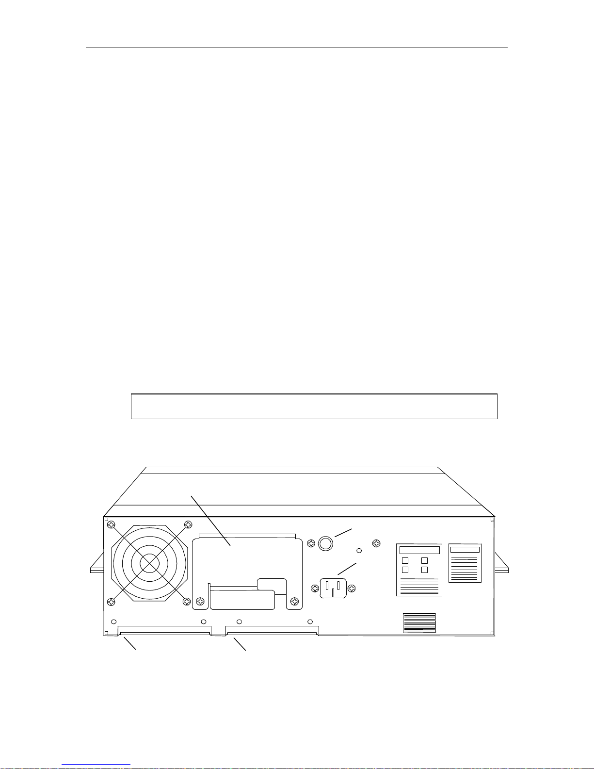
1.7.5 Industry Standard Interface (non-SCSI)
The computer interface will consist of either two cables with a 50-pin card edge
connector on each, or a single cable branching out into two 50-pin card edge
connectors. The card edge connectors must be connected to J1 and J2 at the rear of
the tape drive (sometimes referred to as J101 and J102 respectively). Connector
locations are shown in Figure 1-10.
1. There are three removable cable entry covers attached to the rear chassis panel
with two Phillips screws each.
a. When using a round interface cable, remove all cable entry covers, pass the
cable through the upper opening and attach the connectors to the PCBA. Then
replace all three cable-entry covers, routing the cable through the slot in the
upper cover.
b. When using flat ribbon cables, remove and store the two lower cable entry
covers. The upper cable entry cover remains in place.
2. Connect the cables to J1 and J2 as shown on the decals.
NOTE
Be sure to turn the tape drive off before attaching the interface cables.
3. Dress the cables, replace the cable entry covers, and secure them with the
Phillips screws.
Upper Cable Entry Cover
Line Fuse
Power
Connector
J2 Pin 1
J1 Pin 1
(Lower cable entry covers not shown)
Figure 1-10 Industry Standard Interface Connector Placement
500300 Rev. U Tape Drive Installation 1-11
1.8 Rack Mount Installation
The tape drive is cooled by an exhaust fan mounted on the rear panel and
depends upon an unrestricted flow of ambient air. The drive must not be
mounted in any enclosure that would restrict the flow of ambient temperature
air to the drive or block the airflow from the exhaust fan. The upper cable entry
cover must be installed to insure proper cooling. If the installation is in
question, please call Qualstar.
All drives ship with rubber feet on the bottom. To prevent possible cabinet
interference when rack-mounting the drive, these rubber feet should be removed.
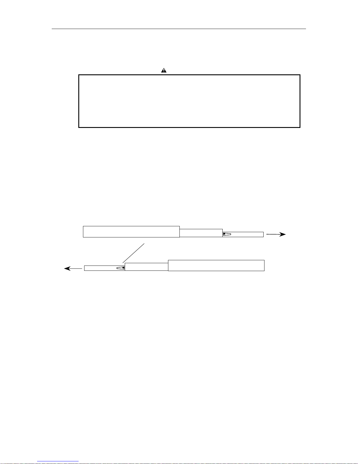
The slides are of a two-piece detachable construction, each consisting of an inner and
an outer rail. The inner rails can be extended from of the outer rails to a
predetermined safety stop, allowing the drive to be accessed for servicing without
removing it from the rack. Each inner rail has a safety lever that must be actuated
before the inner rail can be completely extended and separated from the outer rail.
Refer to Figure 1-11.
CAUTION
Left Hand Outer Slide
Safety Latch –
Move up to release Inner Rail form Outer Rail
Front of Drive
Figure 1-11 Detachable Side Assemblies
Use the following procedure to install the slide:
1. Extend the inner and outer rails of one assembly until they reach the safety
stop. The safety release lever then can be seen in the recessed part of the inner
rail.
2. Pull the safety release lever up and remove the inner rail. Do not separate the
other slide assembly at this time.
3. Using the mounting hardware provided, mount the outer rail into the cabinet.
Do not fully tighten the mounting hardware at this time.
4. Using the hardware provided, attached the inner rail to the side of the drive
and tighten the mounting screws securely.
Front of Drive
Inner Rail
Right Hand Outer Slide
1-12 Tape Drive Installation 500300 Rev. U
5. Separate the inner and outer slides of the remaining assembly and attach the
rails to the drive and to the rack. Figure 1-12 shows the mounting locations for
attaching the slides to the drive.
6. Attach a rack latch to the standoffs provided inside of right side of the bezel as
shown in Figure 1-13.
7. With the help of an assistant, carefully slide the tape drive with attached inner
rails into the outer rails. The rails should engage smoothly and evenly.
8. Lift both safety latches up, slide the tape drive fully into the cabinet, and
tighten the screws that hold the rails to the rear of the rack.
9. Extend the drive out about a foot, and tighten the front mounting hardware.
The drive is now securely mounted in the rack. To remove the drive, first extend it
forward until it reaches the safety stops. Then pull both safety latches up and slide
the drive forward about an inch. The drive can then be completely removed from the
outer rails.
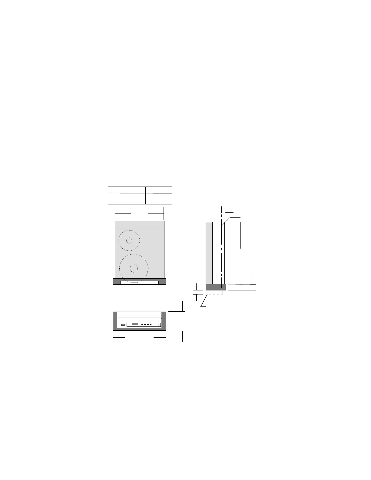
CONFIGURATION
Rack Mount
Table Top
"A"
19.00
Maximum
"A" DIM
17.40
19.00
1.187
1.45
Door Clearance
5.25 Maximum
Note: All Dimensions in Inches
C of Slide
L
22.9
2.30
Figure 1-12 Mounting Dimensions
500300 Rev. U Tape Drive Installation 1-13

Right Cabinet
Mounting Rail
Standoffs
Figure 1-13 Location of Rack Latch
Right Cabinet
Mounting Rail
Inside upper
Right Corner of
Drive Bezel
1-14 Tape Drive Installation 500300 Rev. U
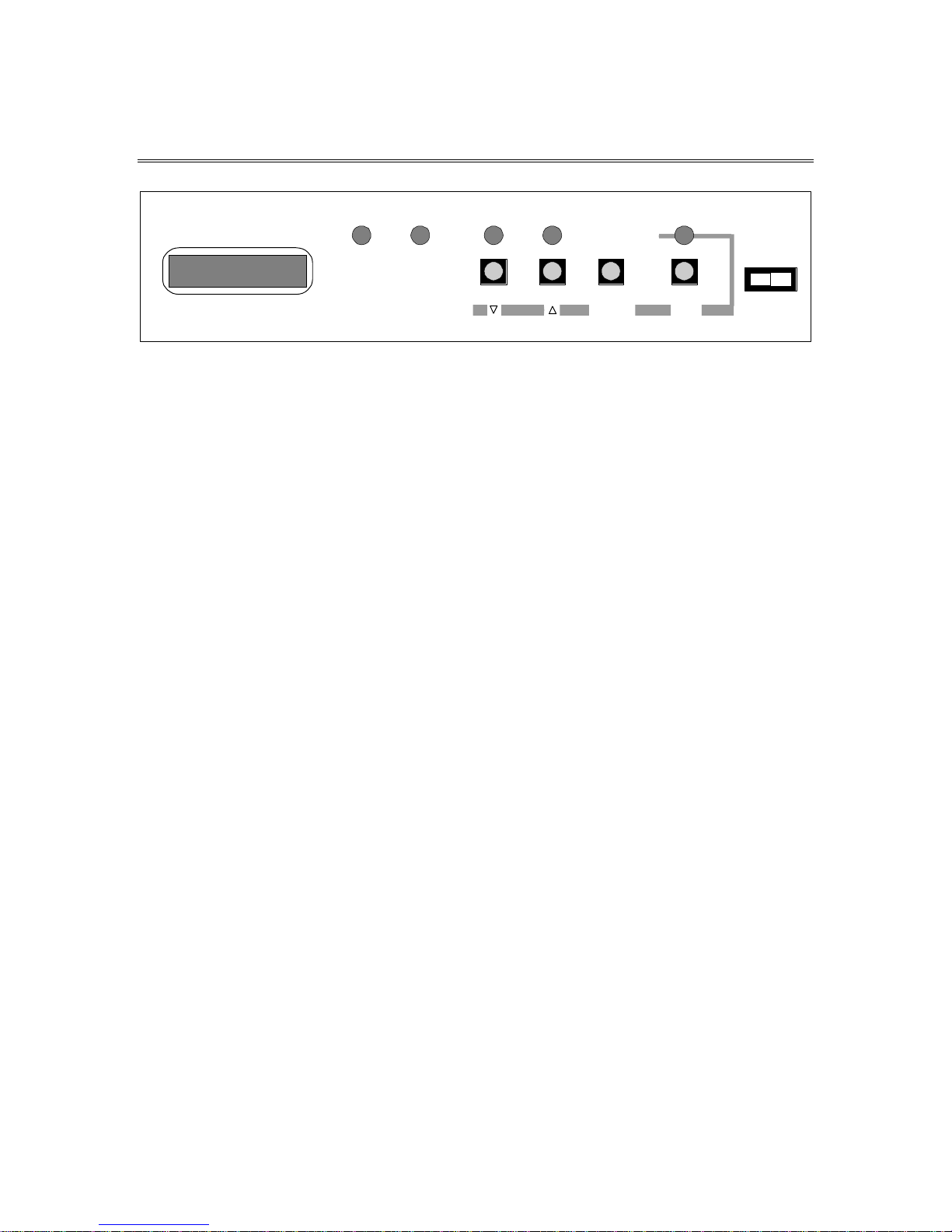
2. Controls and Indicators
BUSY FPT LOAD ONLINE DENSITY
Figure 2-1 Front Control Panels
2.1 Front Control Panels
2.1.1 Power Switch
The power switch applies power to the drive. Press the left side (I) to turn the drive
on; press the right side (O) to turn the drive off.
2.1.2 Push-button Switches
The four push-button switches serve several purposes depending upon the current
mode of operation. Their functions in the normal operating mode are described in
the following sections.
MENU
ENTER EXIT
POWER
I O
2.1.2.1 LOAD Switch
This switch has five functions in the operating mode:
• Loads the tape if it is not already loaded.
• Rewinds the tape if it is past BOT and if the drive is off-line.
• Unloads the tape if it is held for one second while the tape is at BOT and the
drive is off-line.
• Toggles between REWIND and REWIND/UNLOAD if the tape is rewinding.
• Aborts a Load operation if pressed before the tape leader reaches the take up
reel.
2.1.2.2 ONLINE Switch
The ONLINE switch toggles the drive between the online and off-line states. When
the tape is unloaded, the drive is in the standby state and the ONLINE switch has
no effect.
500300 Rev. U Controls and Indicators 2-1

Pressing ONLINE while the tape is loading will toggle the pending online state. A
LOADING message indicates the drive will not go online at the completion of the load
sequence; an ONLINE PEND message indicates the drive will automatically go online
after the load sequence is complete.
Once the tape has been loaded, the ONLINE switch toggles the online state as
indicated by the ONLINE indicator. The online status is also sent to the host. When
off-line, the tape drive cannot accept host commands. You may also toggle the online
state while the tape is rewinding.
Placing the drive off-line during a write operation may prematurely terminate a data block and
should only be done to abort a runaway condition. Placing the drive off-line during a read
operation will terminate the read sequence after the present block has been completely read.
2.1.2.3 DENSITY Switch
When the drive is in the standby state or when it is off-line and the tape is at BOT,
pressing the DENSITY switch cycles the selected density from 800, 1600, 3200,
6250, 6250s, and back. When the tape is beyond BOT, the DENSITY switch is
disabled. The beginning of display line one shows the density you selected.
NOTE
A small letter S following the 6250 indicates that slow-GCR (62.5 IPS) is selected, as opposed to
the normal GCR tape speed of 125 IPS. This mode is available only on certain models. In
addition, these models can be configured via the Drive Configuration menu to move tape only
at 62.5 IPS during GCR operation, or only at 125 IPS, in which case the S will not appear.
If a drive does not support a particular density, that density will not be displayed.
800 CPI is a read-only density.
2.1.2.4 MENU Switch
The MENU switch toggles the Menu mode on and off as indicated by the MENU
indicator. When in the Menu mode, all four push-button switches assume new
functions. Refer to Chapter 4 for more information.
2.2 Front Panel Indicators
Five LED indicators on the front panel display additional drive status when on:
• BUSY - The tape is in motion and the door or top cover should not be opened.
NOTE
• FPT - Where is no write-enable ring on the supply reel, or 800 CPI has been
selected, or the Read Only mode is on. In each case, the drive is File Protected
and will not write on or erase the tape.
2-2 Controls and Indicators 500300 Rev. U

• LOAD - The tape is loaded and positioned at loadpoint (BOT).
• ONLINE - The tape is loaded and the drive is online and ready to accept a
command.
• MENU - The drive is in the menu mode, as opposed to the operating mode.
You use the menu mode to select drive options and operating parameters, and to
perform diagnostic tests. It is available to you only when the drive is offline or in the
standby state. The operating mode is the normal mode—i.e., offline, online, or
standby.
2.3 Liquid Crystal Display
The drive displays status, error conditions, parameter values, and other information
on a liquid crystal display (LCD). The LCD contains two lines of sixteen characters
each. Throughout this document, display line one refers to the top line, and display
line two refers to the bottom line. Figure 2-2 illustrates the states of the LCD at
various times during drive operation.
500300 Rev. U Controls and Indicators 2-3

MODEL 3412S
6250sSTANDBY #0
6250s 65% 10.5“
6250s 95%<E.EOT
Display Line One
Initial Density
(A) DURING POWER- UP:
SELF-TEST NO. 19
(B) TAPE UNLOADED:
Display Line Two
Drive Address (blank if
SCSI Drive)
S = Indicates Slow
GCR (62.5 ips)
Display Line Two
Write-from-BOT density
Read-from-BOT density
Operating density
(C) DRIVE OFFLINE:
6250sOFFLINE
(D) TAPE DRIVE ONLINE
AND TAPE AT BOT:
6250s 0% 10.5“
6250 RD 6250 ID
(E) TAPE SOMEWHERE IN THE
MIDDLE AND NOT MOVING:
(F) TAPE NEAR EOT AND
MOVING REVERSE:
(G) TAPE AT OR BEYOND EOT
AND MOVING FORWARD
6250S 100%> EOT
Status
Status
Reel Diameter
Detected density
Tape Indicator (Online)
E.EOT indicates Early
End Of Tape
(≤90 feet remaining)
EOT indicates at or past
End Of Tape
Figure 2-2 LCD during Various Phases of Operation
2.3.1 Display Line One
2.3.1.1 Density Indicator
Following a load sequence, display line one indicates the density at which the tape
will write. Once the tape drive has received a read or write command and the tape
has moved away from BOT, this density indicator shows the density at which the
drive will read and write, or the operating density. Different models support
2-4 Controls and Indicators 500300 Rev. U

different densities. When the density indicator shows 6250, a small letter S to the
right of the density indicates “slow-GCR”—GCR at 62.5 IPS.
2.3.1.2 Status
• STANDBY - Indicates the tape is not loaded.
• OFFLINE - Tape is loaded but the drive is offline and unable to accept a host
command.
• XXX% - Tape indicator — see Section 2.3.1.5.
2.3.1.3 Drive Address
The drive address appears when the drive is in the Standby condition (not applicable
to SCSI drives).
2.3.1.4 Reel Size
All models support 6, 7, 8.5, and 10.5-inch reels.
The reel diameter message is replaced with the Early EOT message (E.EOT) when
there is less than approximately 70 feet of tape remaining on the supply reel before
the physical End-Of-Tape (EOT) tab. When the EOT tab is physically past the
read/write head, the display changes to EOT, indicating the true end of tape has
been reached.
2.3.1.5 Tape Indicator
The tape indicator appears in display line one whenever the drive is online and
ready to accept host commands. It displays the amount of tape on the take up reel as
a percentage of the total amount of tape on the supply reel, regardless of the supply
reel size. The tape indicator display is continuously updated as the tape moves, and
a direction arrow appears to the right of the percent sign whenever the tape is
moving. A right arrow (→) indicates the tape is moving forward (towards EOT) and
a left arrow (←) indicates the tape is moving reverse. Forward motion causes the
percentage of tape on the take up reel to increase.
2.3.2 Display Line Two
2.3.2.1 Density Indicators
At the completion of a load sequence, the left side of display line two indicates the
density at which the drive will read, and the right side indicates the pre-existing
density of the tape, i.e., the detected density. The detected density is determined by
reading the ID burst on the tape during the load sequence. An asterisk ( * ) after the
detected density display indicates that no ID burst was found on the tape. In this
case, the detected density assumes the value of the NO-ID DEN parameter (either
Blank, 800 or 3200) which you can select in the Drive Configuration Menu (see
Chapter 4).
500300 Rev. U Controls and Indicators 2-5

Display line two continues to indicate the read and detected densities when the
drive is placed online. When the tape moves forward from BOT, display line two
becomes a message line and its density indicators will be erased.
2.3.2.2 Messages
The message line is used to display general information, instructions, error
conditions, and other data depending upon the current situation.
2-6 Controls and Indicators 500300 Rev. U

3. Operating Instructions
3.1 Applying Power
1. Before plugging in the tape drive, switch the power switch to the OFF position
as shown in Figure 3-1.
Figure 3-1 Power Switch Location
2. Observe the label on the rear panel to verify the drive is already configured for
the available AC voltage. It the available voltage differs, refer to Chapter 8 of
this manual to change the voltage selection.
3. Connect the power cord to the rear of the drive as shown in Figure 3-2 and
then switch on the tape drive.
Figure 3-2 Power Connection Location
500300 Rev. U Operating Instructions 3-1
 Loading...