

Qualstar 1260 User Manual

Corporation
1260
User's
Guide
500250 Rev. K

Caution!
ii
Copyright
Notice
Information contained
in
this
document is copyrighted by
Qualstar
Corporation.
It
is
intended
for
use
by
Qualstar's
customers
and
prospective customers to
evaluate,
inte-
grate, operate
and
maintain
Qualstar
products. Customers
and
prospective customers
may
reproduce
this
document
as
needed for
these
uses. Reproduction
in
whole
or
in
part
for
any
other
use
or
by
any
other
party
is
prohibited
without
prior
written
permis-
sion from
Qualstar
Corporation.
Every effort
has
been
made
to
keep
the
information contained
in
this
document
cur-
rent
and
accurate
as
of
the
date
of
publication or revision. However, no
guarantee
is
given
or
implied
that
the
document
is
error-free
or
that
it
is
accurate
with
regard
to
any
specification.
Qualstar
reserves
the
right
to modify product designs
and
specifica-
tions
without
notice.
• Qualstar® is a registered
trademark
of
Qualstar
Corporation.
• Cipher® is a registered
trademark
of
Archive Corporation.
• Pertec®
is
a registered
trademark
ofDDC Pertec
..
•
IB~
is
a registered
trademark
of
International
Business Machines, Incorpo-
rated.
References contained in this manual to
DIP
switch settings,
jumper
loca-
tions, primary voltages and other options are for reference only.
Access
to the interior
of
this equipment
is
restricted
to
dealers and qualified
service technicians, and only in accordance with published service
manu-
als and bulletins.
For
service information
or
help
with
installation,
please
write
or
call
Qualstar
Customer Support:
Qualstar
Corporation
6709
Independence
Avenue
Canoga
Park,
CA 91303
FAX:
(818) 592-0116
Phone:
(818) 592-0061
500250K
Important
-
Read
This
Before
Opening
the
Package
Qualstar
merchandise arrives
pany
these
If
or
If
•
•
• Call
• Clearly identify
• Return
Corporation
immediately.
instructions.
this
merchandise was
reseller for
this
Treat
Retain
shipped to
packing
chandise Authorization (RMA) number.
cepted
ments to:
return
merchandise was
the
merchandise carefully to
all shipping
Qualstar
material
Qualstar
without
the
merchandise, including cables, manuals, software
has
made
every effort to provide
damaged
If
the
instructions.
and
in
or carton
Customer Service
this
number.
the
outside of
or
has
merchandise
purchased
purchased
packing materials.
the
original packing
has
the
been
at
carton and
been mishandled,
is
defective
from a
dealer
or
directly from
assure
damaged, a new
(818) 592-0061 to
Qualstar,
its
suitability
Returned
material
Returned
the
packing list with
quality
in
any
other
and
merchandise will
merchandise.
please
notify
other
way, please follow
reseller, contact
please do
for
return.
merchandise
carton.
set
may
request a Return
and
the
delivery com-
that
the
following:
must
be
If
the
original
be
requested.
Mer-
not
be ac-
the
RMA
number.
all related docu-
If
the
dealer
QUALSTAR
6709
Federal
This
equipment
puting
provide reasonable protection
cial environment. Operation
ceptable interference to radio
expense will be required to
Communications
has
been
device
pursuant
to
tested
Subpart
take
CORPORATION
Independence
Canoga
Attn:
Phone:
Park,
Customer
FAX: (818) 592-0116
(818) 592-0061
Commission
and
found to comply
J of
Part
15 of FCC Rules, which
against
of
and
such interference
this
equipment
TV reception,
whatever steps
Avenue
CA
91303
Service
with
the
when
in a residential
in
which case
are
necessary to correct
Requirements
limits for a Class A com-
are
designed to
operated
area
the
may
user
the
in
a commer-
cause unac-
at
his
own
interference.
500250 K
iii
iv
Limited
Warranty
QUALSTAR SHALL NOT BE RESPONSIBLE OR LIABLE FOR
AA"Y
SPECIAL, IN-
CIDENTAL
OR CONSEQUENTIAL DAMAGES OR LOSS
L~~ISING
FROM
THE
USE
OF
THIS
PRODUCT.
THIS
WARRANTY IS
IN
LIEU OF, AND BUYER WAIVES, ALL OTHER WARRANTIES, EXPRESSED OR IMPLIED, ARISING BY LAW OR OTHERWISE, INCLUDING WITHOUT LIMITATION ANY IMPLIED WARRANTY
OF
MERCHANTABILITY OR FITNESS FOR A PARTICULAR PURPOSE.
THE
REME-
DIES STATED
IN
THIS WARRANTY ARE EXCLUSIVE.
Qualstar
Corporation
warrants
this
Magnetic Tape
Transport
or Tape Subsystem to
be free from defects
in
materials
and
workmanship
under
normal
use
and
service for a
period
of
one
year
from
the
date
of
shipment
from
the
factory to
the
buyer, provided
however
that
goods
or
parts
which
are
replaced
or
repaired
under
this
warranty
are
warranted
only for
the
remaining unexpired portion of
the
original
warranty
period
applicable to
the
goods
in
which
they
are
installed. This
warranty
does
not
apply
to ac-
cessories such
as
tape, carrying cases,
or
manuals.
Qualstar's
sole
and
exclusive obligation
under
this
limited
warranty
is
to
repair
or re-
place
at
Qualstar's
option all products
that
are
returned
to
Qualstar
within
the
appli-
cable
warranty
period
and
found
by
Qualstar
to
be
defective. Replacement
parts
may
be
either
new
or
reconditioned
at
Qualstar's
option. The Buyer is responsible for prop-
erly packing
the
unit
to be returned
in
accordance with applicable user's guide instruc-
tions,
and
the
Buyer shall ship
the
unit
prepaid
at
Buyer's expense.
Qualstar
will
return
the
unit
to
the
Buyer prepaid
at
Qualstar's expense via surface transportation. Air trans-
portation, customs charges, and other special charges are
the
responsibility of
the
Buyer.
This
warranty
shall
immediately be
null
and
void if,
in
Qualstar's
sole judgement,
the
unit
has
been
altered
or repaired
other
than
with
authorization from
Qualstar
and
by
its
approved procedures,
has
been
subject to misuse, abuse, negligence
or
accident,
damaged
by
excessive voltage, damaged
in
shipment, subjected to
improper
environ-
mental
conditions
or
had
its
serial
numbers
and/or
other
product
markings
altered,
de-
faced
or
removed. Normal
user
preventive
maintenance
such
as
tape
path
cleaning
as
set
forth
in
Qualstar's
User's Guides is
the
responsibility of
the
Buyer
and
is excluded
from
this
warranty.
This
warranty
will
remain
in
effect
notwithstanding
Buyer's
shipment
to
third
par-
ties,
but
warranty
remedies defined
herein
are
applicable only to
Buyer
and
are
not
transferable.
Buyer
shall disclose to
third
parties
the
terms
of
this
warranty
and
shall
indemnify
Qualstar
from
any
failure to
make
such disclosure
and
from
any
warranties
made
by
the
Buyer beyond those
set
forth herein.
Qualstar
makes
no representations
as
to
the
suitability
of
Software supplied for
use
in
any
application,
and
the
Buyer agrees to accept all such Software on
an
"as is" basis.
Furthermore, Qualstar does not
warrant
Software to be free from defects,
and
assumes
no
responsibility for damages of
any
kind,
either
actual
or consequential, for
such
Soft-
ware
failing to perform
as
documented
or
in
any
other
manner.
In
no
event
will Qual-
star
be liable for damages, including
any
lost profits, lost savings
or
other
incidental
500250 K
500250 K
or
consequential
damages
arising
out
of
the
use
or
inability
to
use
such
software, even
if
Qualstar
has
been
advised
of
the
possibility
of
such
damages,
or
for
any
claim by
any
other
party.
Qualstar
Service
Policy
Service
is
provided
at
the
Qualstar
factory
in
Canoga
Park,
California, USA. Addition-
ally, service
may
be available on
site
or
in
selected locations from a
Qualstar
factory-
authorized
service organization. Consult a
Qualstar
sales
representative
for
further
information.
All
material
returned
to
the
Qualstar
factory for
any
reason
must
be
authorized
prior
to
shipment. Write or Call
Qualstar
Customer
Service to
obtain
an
RMA
number.
This
number
must
appear
on all boxes
and
packing slips.
Qualstar
will refuse delivery
ofma-
terial without proper
RMA
identification.
Units
being
returned
must
be
shipped
in
the
original packing
material
and
shipping
carton. Any
damage
or
expenses
resulting
from
shipping
in a non-authorized
shipping
carton
will be
the
responsibility
of
the
Buyer.
If
the
original
carton
and
packing
are
not
available,
they
may
be
purchased
from
Qualstar.
In-Warranty
Service
If
this
merchandise
was
purchased
from a dealer/reseller, consult
that
dealer/reseller
for instructions.
Qualstar's
warranty
obligation
is
to
the
original
purchaser
(dealer/re-
seller) only.
If
this
merchandise
was
purchased
directly from
Qualstar,
in-warranty
service will be
provided
at
the
Qualstar
factory
in
Canoga
Park,
California, USA.
The
Buyer
is re-
sponsible for all freight charges
incurred
in
returning
the
merchandise
to
the
factory.
Qualstar
will
return
the
merchandise
to
the
Buyer
prepaid
at
Qualstar's
expense
by
surface
transportation.
The expense
of
air
transportation,
if
requested,
is
the
responsi-
bility
of
the
buyer.
In-warranty
service
may
also
be
available on-site
or
at
selected
Qualstar
factory-
authorized
service
centers
for
an
additional charge. Consult a
Qualstar
sales
repre-
sentative
for
further
information.
Out-Of-Warranty
Service
Should service
be
required
after
the
warranty
period
has
expired,
Qualstar
will
repair
and
test
the
tape
drive
or
tape
subsystem
for a flat fee
as
shown
in
the
current
price
list. Service charges, freight
and
customs charges will
be
billed to
the
Buyer.
An
Extended
Service Agreement, available for
units
located
within
the
United
States,
may
be
purchased
which
extends
the
warranty
period for one year.
Units
covered un-
der
the
Extended
Service Agreement
may
be
serviced
as
often
as
required
during
the
contract
period. Prices
are
shown
in
the
Factory Service Price
List
and
include
return
freight
by
surface
transportation.
Qualstar
customer service
representatives
can
pro-
vide details on
the
Extended Service Agreement.
v
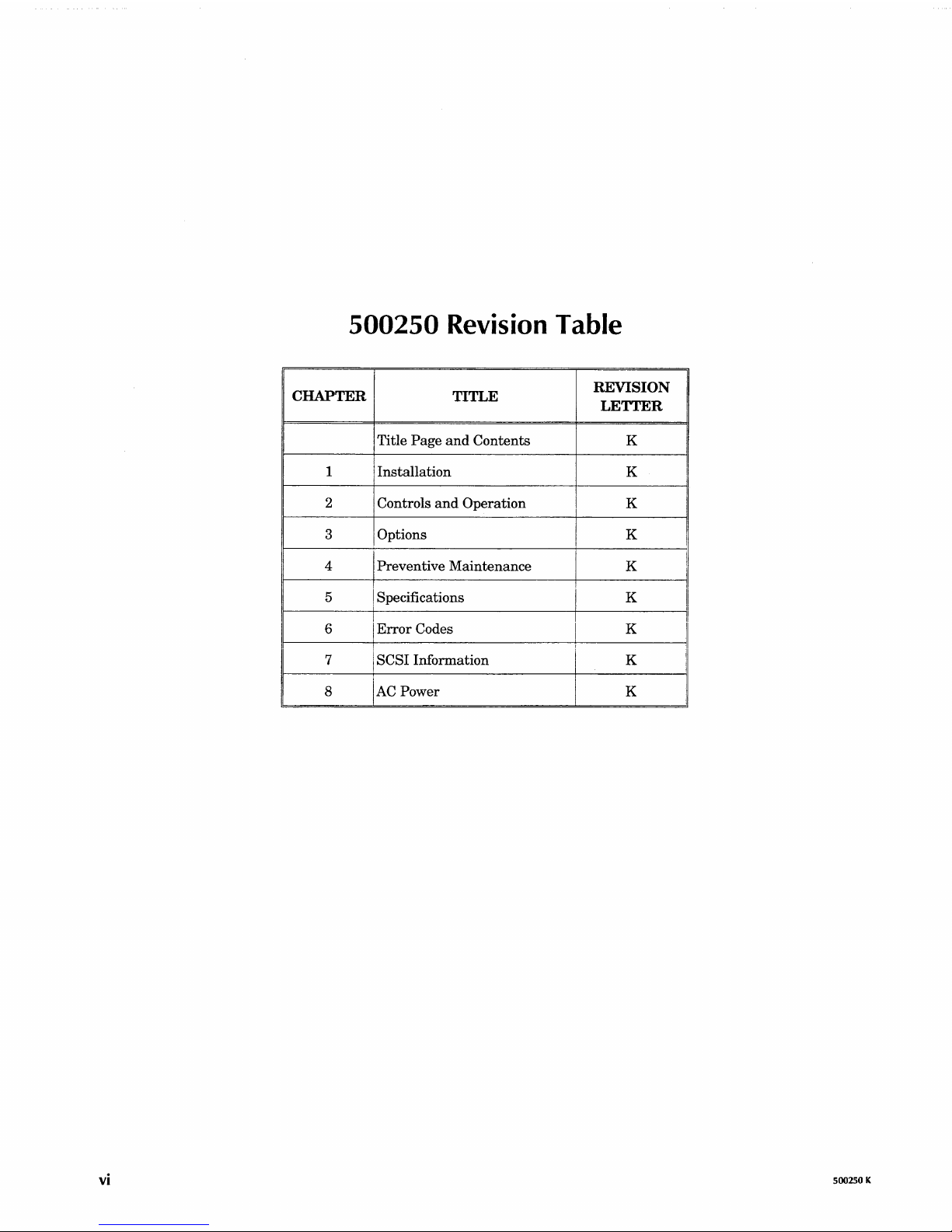
500250
Revision Table
CHAPTER
TITLE
REVISION
LETTER
Title
Page
and
Contents
K
1
Installation
K
!
2 Controls
and
Operation
K
3
I Options
K
I
4 Preventive
Maintenance
K
I
I
!
I I
5
I Specifications K
i
I
6
Error
Codes K
I
r
I
I
7
I SCSI Information
K
!
8
K
AC
Power
vi
500250 K
500250 K
Table
of
Contents
Chapter 1. Tape Drive Installation
1.1. Introduction
1.2. Model Identification
1.3.
Operating Environment
1.4.
Power Requirements .
1.4.1. Power Connections .
1.5. Tools Required for Installation
1.6. Unpacking
1.7.
Orientation
1.8. Interface Connections
1.8.1. Model 1260 .
1.8.2.
1260B .
1.8.3.
12605 . . . .
Chapter 2. Controls and Operation
2.1. Controls
and
Indicators
2.1.1. LOAD Switch and Indicator
2.1.2. ONLINE Switch and Indicator
2.1.3.
FPT
Switch and Indicator .
2.1.4.
6250 Switch and
Indicator.
2.1.5. Power Switch
2.2 . Tape Operation
2.2.1. Applying Power .
2.2.2. Loading a Tape .
2.2.3. Loading with Tape
Already Threaded
2.2.4. Loading Near
EOT
...
.
2.2.5.
Unloading a Tape
...
.
2.2.6.
File-Protecting the Drive .
2.2.7. Changing Data Densities.
2.2.8. Aborting
Runaways
...
2.3. Using the Demonstration Mode .
2.3.1. Activating the Demonstration Mode
2.3.2. Deactivating the Demonstration
Mode.
Chapter 3. Field Selectable Options
3.1. Option Switches
3.1.1. Diagnostic
Enable
(Sl) .
3.1.2.
Enable
ICER
(52)
.....
.
3.1.3.
IDBY during Filemark
Search
Commands
(S3)
3.1.4. Filemark Gap Length
(54)
....
3.1.5. Extended Write Gaps
(S5
and
56)
3.1.6. Default Density
(57)
......
.
3.1
.7. Automatic Density Select
(58)
3.2. Option Jumpers
Page
1-1
1-2
1-2
1-2
. 1-2
1-3
1-3
1-3
1-4
1-4
1-5
1-5
Page
2-1
2-1
2-1
2-1
2-1
2-2
2-2
2-2
2-2
2-3
2-3
2-4
2-4
2-4
2-4
2-4
2-5
. 2-5
Page
3-1
3-1
3-1
3-1
3-2
3-2
3-3
3-3
3-4
vii
3.2.1. Formatter Address
3.2.2. Formatter
Status
3.2.3.
W10, W11, W12
3.2.4.
IFEN
3.2.5.
3.2.6. Read/Formatter
Enable
Control
Signals
Abort (W13)
Wl
(WO
- W7)
(WS)
......................
............................
. . . . . . . .
.........................
. . . . . . . . . . . . . . . . . . . . . . . . . . . . .
(W9) . . . . . . . . . . . . . . . .
..............
.. . ......
.
.
.
.
.
3-4
3-4
3-4
3-5
3-5
3-5
Chapter 4. Preventive Maintenance
4.1. Preventive Maintenance Schedule .
4.1.1.
Why
4.1.2. Frequency
4.2. Tape
Preventive Maintenance
of
Preventive Maintenance
Path
Cleaning Procedure
Is
Necessary
Chapter 5. Specifications
5.1. Data Specifications
5.1.1. Data Formats
5.1.2. Data Transfer
5.1.3. Media Requirements
....
Rate
...............
.
5.2. Data Capacities
5.2.1. Tape Length
5.2.2. Recording Density
IBG
5.2.3.
5.2.4.
5.2.5. Number
5.2.6. Data Capacity, Unformatted
5.2.7. Data Capacity, Formatted at
5.2.S. Data Capacity, Formatted at 3200 cpi
5.2.9. Data Capacity, Formatted at
Length . . . . . . .
Block Length
........
.........................
of
Filemarks
.....
..
.....................
.........................
1600 cpi
6250 Cpi
. . . . . . .
. . . . . . . . .
.
..............
.................
.........................
Chapter 6. Error Codes and Operational Failures
6.1.
Load
Fault
6.2.
File
Protect Fault
Read
6.3.
6.4.
6.5. Write/Erase
6.6. Write/Erase
6.7. Motion Fault
6.8.
6.9.
After Write Fault
Start/Position Fault .
Power On Fault
Power
Fail
BOT Fault
1260S
Error
Indications
Fault
........
........
Page
4-1
.
4-1
...
4-2
4-2
Page
5-1
.
......
.....
5-1
5-1
5-1
5-1
.
.
.
.
.
......
.
.
.
5-2
5-2
5-2
5-2
5-2
5-3
5-3
5-4
5-4
.
Page
6-1
6-1
6-2
6-2
6-2
6-2
6-2
6-3
6-3
Chapter 7. Supplemental
7.1. Changing the
7.2. Model
Identification
7.3. Model 1260S Description
7.3.1. General
7.3.2.
SCSI
7.3.3.
Single-Ended Configuration
7.3.4. On-Board Buffer .
7.3.5.
Long
7.3.6.
SCSI
viii
SCSI
ID.
...........
Power-Up Self
Blocks
....
Configuration
Test
SCSI
Drive Information
.
.
..
.
..
................................
.
Page
7-1
7-2
7-2
7-2
7-3
7-3
7-3
7-4
7-4
500250 K
500250 K
7.4. Differences between
SCSI
and the Pertec Interface
7.5.
SCSI
Bus
Description .
7.6. Cables and Connectors
7.7.
SCSI
Bus
Termination .
7.7.1. Internal Terminators .
7.7.2. External
Terminators.
7.7.3. Termination Power
..
7.B.
Switches,
LEOs,
and Jumpers
7.8.1. SwitchbankS1
.....
.
7.8.2. Pushbutton
S2
......
.
7.8.3. Display
Indicators DS7 through
DSO
.
7.8.4. Switchbank
S3
...
.
7.8.5. Jumpers
...........
.
7.9. Resetting the
SCSI
PCBA .
7.10.
SCSI
PCBA Configuration Modes
7.10.1.
Mode
0 - Normal
Operating
Mode
. .
7.10.2.
Mode
1 -
View
Configuration Data
..
7.10.3.
Mode
2 - Alter Configuration Data
..
7.10.4.
Mode
3 - Reload RAM from EEPROM
7.10.5.
Mode
4 -
Save
Configuration
..
.
7.10.6.
Mode
5 - Factory Default
....
.
7.10.7.
Mode
6 through
Mode
0 -
NoOp
7.10.8.
ModeE-FactoryTest
....
7.10.9.
Mode
F - Continuous Self-Test
7.11. Changing
SCSI
Parameters .
7.12.
SCSI
Configuration Parameters
7.12.1.
SCSI
Device 10 (Address 00)
7.12.2.
SCSI
Parity (Address 01) .
7.12.3.
SCSI
Sync (Address 02)
..
7.12.4. Space
Write
(Address 03) .
7.12.5.
Write
EOT (Address 04) .
7.12.6.
Write
Retries (Address 05)
7.12.7. Address 06
.......
.
7.12.8. Buffer Switch (Address
07)
7.12.9. Early EOT (Address 08)
..
7.12.10. EOM
On
Read
(Address 09) .
7.12.11.
Set
Inquiry Data (Address
OA)
.
7.12.12. Lng
Blk (Address
OB)
...
.
7.12.13.
AddressOC-OD
.....
.
7.12.14.
Read
Bad Data (Address
0)
.
7.12.15.
Read
EOT Stop (Address
OF)
7.12.16.
Read
Ahead (Address 10) .
7.12.17.
Read
CER
(Address 11)
..
7.12.18.
Read
Retries (Address 12) .
7.12.19. Residue (Address 13) .
7.12.20. Unload (Address 14)
...
7.12.21.
SCSI
LUN (Address 15)
..
7.12.22. Rewrite
CER
(Address 16) .
7.12.23.
Write
CER
(Address 17)
7.12.24. Busy (Address 18) . . . . .
7.12.25.
Read
HER
(Address 19)
..
7.12.26.
Write
HER
(Address 1A)
..
7.12.27. Block Length (Address 1B)
..
7.12.28. Address 1 C -
AF
. . . . . . .
7.12.29.
Inquiry Data File (Address
BO -F5)
7.12.30. Address
F6 -FD
.........
.
7.12.31. Drive
Model
Number
(Address
FE)
7-4
7-5
7-5
7-6
7-6
· 7-6
· 7-7
7-B
7-8
· 7-8
· 7-9
7-10
7-11
7-11
7-11
7-12
7-12
7-13
7-13
7-14
7-14
7-15
7-15
7-15
7-15
7-16
7-17
7-17
7-19
7-19
7-19
7-20
7-20
7-20
7-21
7-21
7-21
7-25
7-25
7-26
7-26
7-26
7-26
7-27
7-27
7-27
7-28
7-28
7-28
7-29
7-29
7-30
7-30
7-30
7-30
7-30
7-30
ix
x
7.12.32. Checksum (Address
FF)
..................
.
7.13. Drive Configuration Requirements
7.13.1. Formatter Address
(WO
- W7)
...........................
.
7.13.2.
IFEN
(W8)
.....................................
.
7.13.3.
Status
Control
Signals
(W9)
............................
.
7.13.4.
IFEN
Abort (W13)
..............................
.
7.13.5. Read/Formatter
PCBA
W1
.............................
.
Chapter 8. AC Power Configuration
8.1. Tools Required to Change
AC
Power Configuration
8.2.
Opening the Drive
8.3. Closing the Drive
8.4. Configuring the Drive for
Available Power
7-31
7-31
7-31
7-31
7-31
7-31
7-31
Page
8-2
8-2
8-2
8-2
500250 K
500250 K
Tape
Drive
Installation
1.1
Introduction
This guide provides
installation
instructions
and
techniques for
operating
the
Qual-
star
1260 series
tape
drives.
In
order
for
the
tape
drive to operate,
it
must
be
con-
nected to a
tape
coupler
card
within
your
computer. Refer to
the
specific coupler
manual
for
the
installation
and
configuration
of
the
tape
coupler before
installing
your
tape
drive.
1
The
software provided
with
the
coupler controls
the
transfer
of
data
to
and
from
the
tape
drive.
The
wide
variety
of options which
Qualstar
offers allows
the
tape
drive to
operate
with a number
of
different coupler packages.
The
best
choice
of
couplers de-
pends
upon
your
particular
application
and
computer
system.
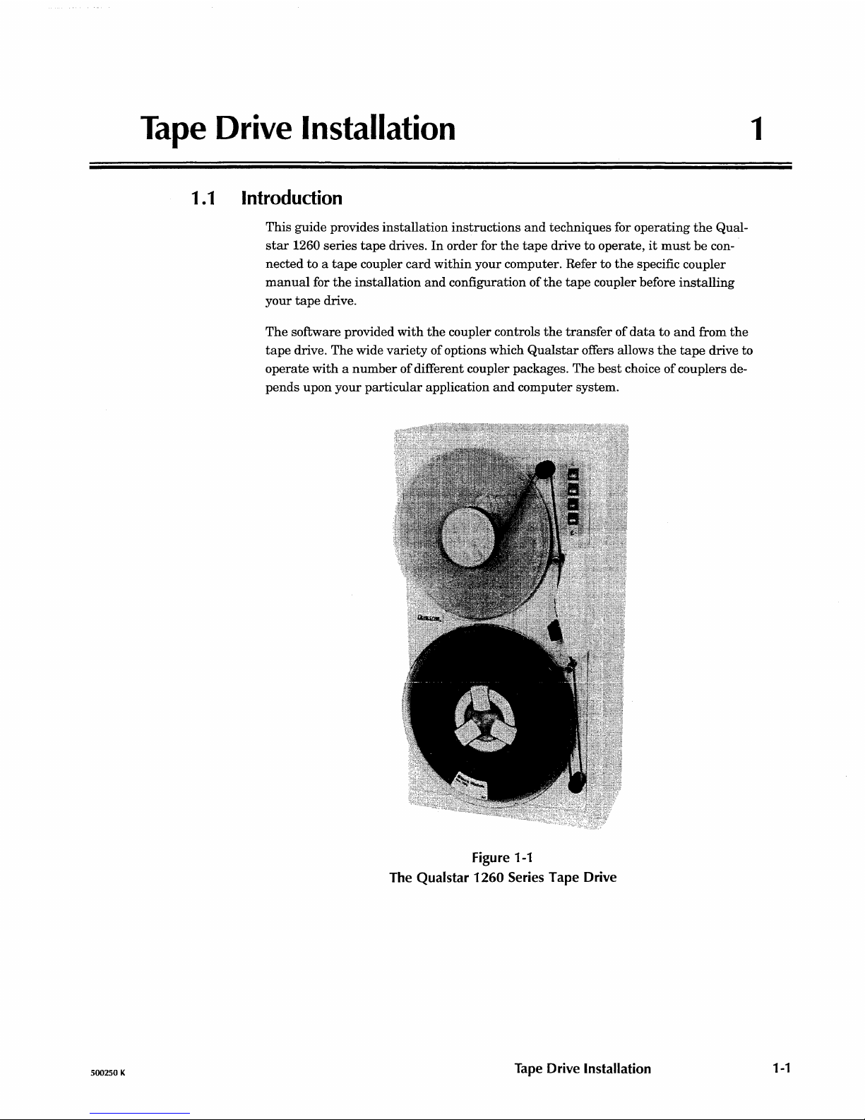
Figure 1-1
The
Qualstar
1260
Series
Tape Drive
Tape
Drive Installation
1-1
1-2
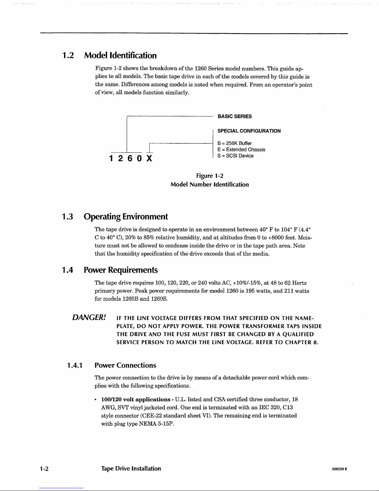
1.2 Modelldentification
Figure
1-2 shows
the
breakdown
of
the
1260 Series model
numbers.
This
guide ap-
plies
to
all models.
The
basic
tape
drive
in
each
of
the
models covered
by
this
guide
is
the
same. Differences
among
models is
noted
when
required.
From
an
operator's
point
of
view, all models function similarly.
1 2 6 0 X
1
.3
Operating
Environment
BASIC SERIES
SPECIAL CONFIGURATION
B = 256K Buffer
E = Extended
Chassis
S = SCSI
Device
Figure 1-2
Model Number Identification
The
tape
drive is designed to
operate
in
an
environment
between
400 F to 1040 F (4.4
0
C to 400 C), 20% to 85% relative humidity,
and
at
altitudes
from 0 to +8000 feet. Mois-
ture
must
not
be
allowed to condense inside
the
drive
or
in
the
tape
path
area.
Note
that
the
humidity
specification
of
the
drive exceeds
that
of
the
media.
1 .4
Power
Requirements
The
tape
drive
requires
100,
120,220,
or
240 volts AC, +10%/-15%,
at
48 to 62
Hertz
primary
power.
Peak
power
requirements
for model 1260
is
195
watts,
and
211
watts
for models 1260B
and
1260S.
DANGER!
IF
THE
LINE
VOLTAGE
DIFFERS
FROM
THAT
SPECIFIED
ON
THE
NAME-
PLATE,
DO NOT
APPLY
POWER.
THE
POWER
TRANSFORMER
TAPS
INSIDE
THE
DRIVE
AND
THE
FUSE
MUST
FIRST
BE
CHANGED
BY
A QUALIFIED
SERVICE
PERSON
TO
MATCH
THE
LINE
VOLTAGE.
REFER
TO
CHAPTER
8.
1.4.1 Power Connections
The
power connection to
the
drive is
by
means
of
a detachable power cord which com-
plies
with
the
following specifications.
• 100/120
volt
applications
-
U.L.listed
and
CSA certified
three
conductor, 18
AWG, SVT vinyl
jacketed
cord. One
end
is
terminated
with
an
lEC
320, C13
style connector (CEE-22
standard
sheet
VI).
The
remaining
end
is
terminated
with
plug type NEMA 5-15P.
Tape
Drive Installation
500250 K
500250 K
• 220/240
volt
applications
-
D.L.listed
and
CSA certified
three
conductor, 18
AWG, SVT vinyl
jacketed
cord. One
end
is
terminated
with
an
IEC
320, C13
style connector (CEE-22
standard
sheet
VI).
The
other
end
is
not
terminated.
The
conductors
are
to
be
connected to a customer-supplied plug
as
follows:
Black
or
brown
wire to
AC
hot
(Live);
white
or
blue
wire to
AC
return
(neutral
or
common);
green
or
green
with
yellow
strips
to
chassis
(ground).
The
following
statement
is
included for compliance
with
German
safety
regulations:
Die
Verbindung
ziir Steckdose sollte moglich
kurz
sein,
und
die Steckdose sollte frei
zuganglich bleiben.
(English
translation:
The
connection to
the
power receptacle should be
as
short
as
pos-
sible,
and
the
receptacle should
be
readily accessible.)
1.5
Tools
Required
for
Installation
A #2 Phillips screwdriver
is
required to
install
the
drive.
1.6
Unpacking
Caution! Model
1260
tape drives weigh between
36
and
44
pounds, depending
upon the configuration.
Use caution in lifting.
The
tape
drive
is
shipped
in a specially
designed
double-walled
carton
with
energy-
absorbing
end
caps. The packaging should be stored for possible
future
transportation
purposes.
The
carton
contains
the
following items:
• Tape Drive
• Power Cord
• User's Guide
• Interface Cable(s) (optional)
Remove
the
drive together
with
its
end-caps from
the
carton
and
place
it
on a table.
Then
remove
the
end-caps
and
the
polyethylene bag.
Remove all
other
materials
from
the
carton
and
store
the
end-caps
and
bag
in
the
car-
ton
for
the
possibility
of
future
shipment.
1 .7 Orientation
The
drive
must
be
placed on a
hard
surface; do
not
place
it
on a
typewriter
pad
or
simi-
lar
surface.
It
may
rest
on
its
bottom,
back
or
side.
There
must
be
no obstructions
which would
prevent
air
from freely flowing
into
the
fan inlet(s)
or
exiting
from
the
ventilation slots.
Tape Drive Installation
1-3
1-4
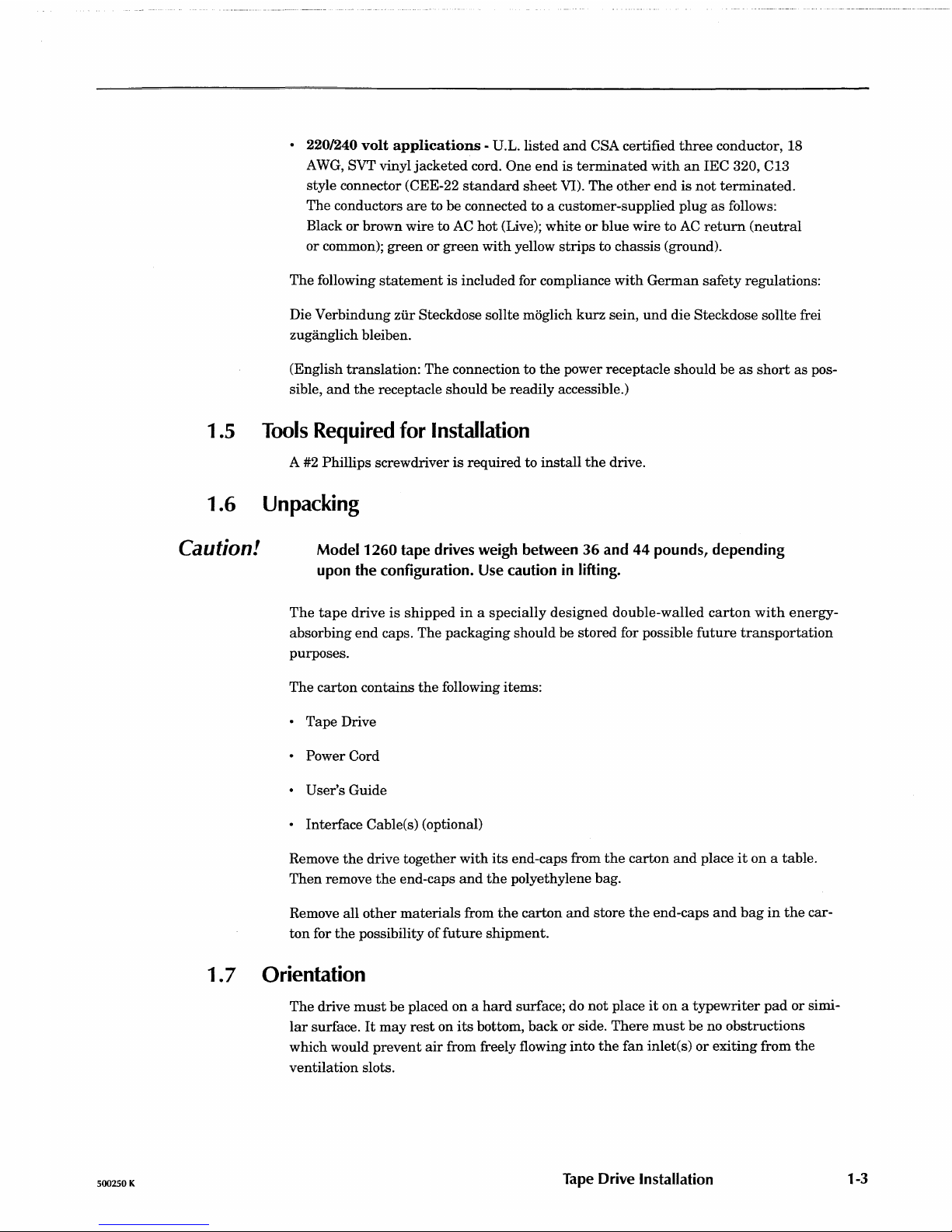
Fanlnleffi
UW
Power
'\~
Switch
roolU
~II
AC
Plug
and
Fuseholder
1260
Without Door Option
With
Door Option
Additional for
SCSI
or
buffer option
o
WIDTH
-I
WIDTH
HEIGHT
12.25 inches 21.50 inches
(31.1 cm)
(54.6 cm)
12.75 inches
21.50 inches
(32.4 cm) (54.6 em)
none none
Figure 1-3
1260 Dimensions
~nT
~
I 1
I I I
HEIGHT
II~~
-I
DEPTH
1-
DEPTH
WEIGHT
8.25 inches
38
pounds
(20.9 cm)
(17.2 kg)
9.25 inches
44
pounds
(23.5 cm)
(19.9 kg)
1 inch 2 pounds
(2.5 cm)
1.8 Interface Connections
1.8.1 Model 1260
Note:
Model 1260
uses
the
Pertec
interface
which
consists
of
either
two
cables
with a 50-pin
card
edge
connector on
each,
or a single
cable
branching
out
into
two 50-pin
card
edge
connectors.
The
card
edge connectors
must
be
connected
to
Jl
and
J2
(sometimes
re-
ferred
to
as
JI0l
and
JI02
respectively)
inside
of
the
tape
drive.
A removable cable
entry
cover
is
attached
to
the
side
chassis
panel
with
two
Phillips
screws. A
round
interface
cable
can
be
fed
through
the
slot
in
the
cover. A decal
shows
the
correct
connector
orientation
of
Jl
and
J2.
1.
Turn
the
tape
drive
offbefore
attaching
the
interface
cables.
2.
With
the
drive
resting
on
its
rubber
feet, remove
the
cable
entry
cover.
3.
Connect
the
cables to
Jl
and
J2
as
shown
on
the
decal.
4.
Dress
the
cables
and
reinstall
the
cable
entry
cover.
The
cable
entry
cover
must be
in
place
to
meet
FCC
requirements.
Tape Drive Installation
500250 K

1.8.2
1.8.3
500250 K
12608
This model contains a Buffer PCBA. Refer to
the
Buffered Interface
Supplement
(docu-
ment
500200) for instructions.
1260S
This
model connects to a SCSI bus. Refer to
Chapter
7 for
further
information.
Tape Drive Installation
1-5


500250 K
Controls and Operation
2
2.1
Controls
and
Indicators
2.1.1 LOAD Switch and Indicator
2.1.2
2.1.3
2.1.4
Use
the
LOAD switch to load, rewind
and
unload tapes.
The
LOAD indicator
is
illuminated
when
the
tape
is
at
Beginning
of
Tape
(BOT.)
\Vhen
the
tape
is unloaded (no tension,)
the
LOAD indicator will flash rapidly
when
a
BOT
marker
is
sensed, providing a
means
of
testing
the
BOT
sensing
circuits.
ONLINE Switch and Indicator
Use
the
ONLINE switch to place
the
drive online
and
offline.
The
drive will only re-
spond to
the
host
ifit
is online. You
may
place
the
drive online
whenever
tape
is
loaded
and
tensioned
and
may
take
the
drive offline
at
any
time.
Pressing
the
switch while a command or rewind operation is
in
progress will abort
the
command
and
place
the
drive offline. All
tape
motion, except for rewind, will halt. You
can
also
use
this
switch to
take
the
drive offline to
abort a runaway
operation.
When
the
Online indicator
is
illuminated,
the
drive
is
online
and
ready
for operation.
When
it
is
not
illuminated,
the
drive is offline
and
will
not
accept
any
commands from
the
host.
FPT
Switch and Indicator
If
the
drive detects
the
presence of a write enable ring on
the
bottom side
of
the
supply
reel,
the
drive will initially be write-enabled. You
can
override
this
condition
and
manually
protect
the
tape
by pressing
the
FPT
switch while
the
LOAD indicator is il-
luminated
and
the
tape
is
at
BOT. The
FPT
switch
has
no effect
when
no
write
ring
is
present.
When
the
drive
is
write-enabled,
it
can
write
on
and
erase
tape. When
the
drive is file-
protected,
its
write
and
erase
circuits
are
disabled. The
FPT
indicator will be illumi-
nated
when
the
drive is
in
the
file-protected
state,
and
will
not
be
illuminated
when
the
drive
is
in
the
write-enabled
state.
The
FPT
indicator serves
as
a power indicator
when a tape
is
not
tensioned.
When
the
tape
is
threaded
but
not
tensioned,
the
FPT
indicator will flash rapidly
when
an
End-Of-
Tape
(EOT)
marker
is sensed, providing a
means
of
testing
the
EOT
sensing
circuits.
6250
Switch
and Indicator
When
the
tape
is unloaded, or
when
it
is
tensioned
and
at
BOT
and
the
drive is
off-
line, you can select
an
operating
density of
either
6250
characters
per
inch (cpi) or
Controls and Operation
2-1
2-2
2.1.5
1600 cpi
by
pressing
the
switch.
When
the
drive
is
online
and
the
tape
is
tensioned
and
at
BOT,
the
host
may
also select
either
density.
The
data
density
for
both
writing
and
reading
is
indicated
by
the
6250
indicator.
When
illuminated,
the
drive
reads
and
writes
at
6250 cpi
and
when
extinguished,
at
1600 cpi.
Either
1600
or
6250 cpi
may
be
selected for a
default
density
upon
power-up
according
to
an
option
switch
setting.
This
should
not
be
confused
with
Automatic
Density
Se-
lect,
which
is
determined
after
the
first
read
operation. Refer
to
Chapter
3 for
more
in-
formation.
Power Switch
The
POWER
switch
is
located on
the
side
of
the
drive
near
the
AC
line
receptacle.
2.2
Tape
Operation
2.2.1 Applying Power
Caution!
It
is
possible to create an undesired flux transition on a tape
if
the tape
is
touching the head when power
is
applied. This
is
not normally a prob-
lem, since the tape
is
not generally loaded when power
is
applied.
If
the
tape
is
threaded past the
BOT
tab, make certain that there
is
at least 1/8
inch gap between the tape and the head before applying power.
2.2.2
Press
the
side
of
the
switch
with
the
"I" to
apply
power.
Listen
for
the
fans.
If
they
do
not
operate,
the
drive
is
not
operational.
Turn
the
power
off, verify
the
power
source
and
then
turn
the
drive
back
on
again.
If
this
fails,
the
drive will
require
service.
After
a
normal
power-up sequence,
the
FPT
indicator
should
be
illuminated.
The
6250 indi-
cator
mayor
may
not
be
illuminated.
Loading a Tape
1.
To
load a reel
of
tape,
unlock
the
supply
hub
by
pressing
the
inside
of
its
three
reel
clamps.
2.
Place
the
tape
reel
over
the
hub
with
the
label
facing out.
3. Lock
the
reel
to
the
hub
by
pressing
the
outside
of
all
three
reel
clamps.
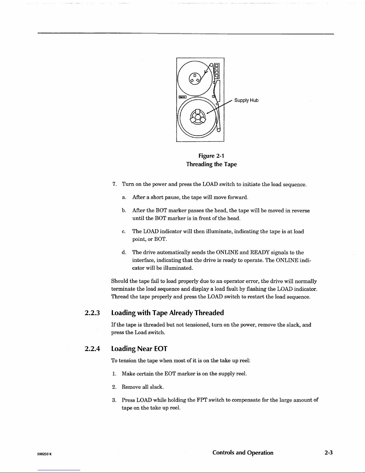
4.
Thread
the
tape
as
indicated
by
the
raised
arrows
on
the
surface
of
the
cast-
ing. Refer
to
Figure
2-1.
5.
Wrap
the
end
of
the
tape
around
the
take
up
hub
such
that
a clockwise
rota-
tion
winds
the
tape
onto
the
hub
and
rotate
the
hub
clockwise
at
least
three
turns.
6. Hold
the
supply
reel
and
rotate
the
take
up
hub
until
all
slack
is
removed.
Controls and Operation
500250 K
2.2.3
2.2.4
500250 K
Supply Hub
Figure
2-1
Threading the Tape
7.
Turn
on
the
power
and
press
the
LOAD switch to
initiate
the
load sequence.
a. After a
short
pause,
the
tape
will move forward.
b. After
the
BOT
marker
passes
the
head,
the
tape
will be moved
in
reverse
until
the
BOT
marker
is
in
front of
the
head.
c.
The
LOAD indicator will
then
illuminate, indicating
the
tape
is
at
load
point, or
BOT.
d.
The
drive automatically
sends
the
ONLINE
and
READY signals to
the
interface, indicating
that
the
drive
is
ready
to operate. The ONLINE indi-
cator
will be illuminated.
Should
the
tape
fail to load properly due to
an
operator
error,
the
drive will normally
terminate
the
load sequence
and
display a load
fault
by flashing
the
LOAD indicator.
Thread
the
tape
properly
and
press
the
LOAD switch to
restart
the
load sequence.
Loading with Tape Already Threaded
If
the
tape
is
threaded
but
not tensioned,
turn
on
the
power, remove
the
slack,
and
press
the
Load switch.
Loading
Near
EDT
To
tension
the
tape
when
most
of
it
is
on
the
take
up
reel:
1.
Make
certain
the
EOT
marker
is
on
the
supply reel.
2.
Remove all slack.
3.
Press
LOAD while holding
the
FPT
switch to compensate for
the
large
amount
of
tape on
the
take
up
reel.
Controls and Operation
2-3
2-4
2.2.5
2.2.6
2.2.7
2.2.8
If
the
tape
comes off
the
supply reel, moisten
the
last
two inches
and
lay
it
over
the
top
of
the
supply reel.
Turn
the
reel counter-clockwise so
that
the
tape
winds onto
the
reel. Continue winding
the
tape
onto
the
reel for five
turns
past
the
EOT
marker.
Hold
the
FPT
switch before pressing
the
LOAD switch
and
then
hold
both
for one sec-
ond to
initiate
the
load sequence.
The
drive will tension
and
rewind
the
tape
to BOT.
Unloading a Tape
1.
If
the
tape
is
stopped
and
not
at
BOT,
take
the
drive offline
and
press
the
LOAD switch to rewind
the
tape.
2.
When
the
tape
is
at
BOT
and
the
drive
is
offline, pressing
the
LOAD switch
initiates
an
unload sequence.
The
drive will wind
the
tape
onto
the
supply
reel
until
the
leader
comes off
the
take
up
hub.
3.
Press
the
inside
of
the
three
supply reel clamps,
and
then
remove
the
reel
from
the
supply hub.
The
drive will also respond to a combination rewind-unload signal from
the
host.
File-Protecting the Drive
You
may
place
the
drive into
and
out
of
the
file-protected
state
when
the
tape
is
at
BOT by toggling
the
FPT
switch until
the
FPT
indicator illuminates.
Changing Data Densities
To
read
prerecorded tapes, you
must
first configure
the
drive to operate
at
the
density
of
the
tape
to be read. 1600 cpi
is
the
most commonly
used
density. You
can
also en-
able
the
Automatic Density Select option described
in
Section 3.1.7.
When
writing on a
tape
from BOT, you
must
choose
the
operating density.
When
ap-
pending
data
to a prerecorded tape, you
must
first configure
the
drive to
operate
at
the
density
at
which
the
tape
was
originally written.
Aborting Runaways
Occasionally
it
may
be
necessary to
abort a tape
operation. This is preferably done
by
the
application program.
If
the
application program is unable to abort a
read
or
write,
you
may
place
the
drive offline
manually
by
pressing
and
holding
the
ONLINE switch
until
the
tape
stops completely. This should also
terminate
the
application program.
Caution! Taking the drive offline while writing can result in an incomplete block be-
ing recorded on the tape, with subsequent
loss
of
data.
2.3
Using
the Demonstration Mode
When
the
drive is
in
the
demonstration mode,
it
will
shuttle
the
tape
at
both
low
and
high speeds, gradually moving
the
tape
towards
EaT.
When
the
tape
reaches EOT,
the
drive will rewind
the
tape
reenter
the
shuttle
mode. This provides
an
effective
Controls and Operation
500250 K
2.3.1
2.3.2
500250 K
means
of
demonstrating
the
drive's
tape
handling
ability. Any size
reel
may
be
used,
and
the
demonstration mode will continue
until
deactivated.
Activating the Demonstration Mode
1.
Thread a tape
and
remove all slack.
2.
Apply power to
the
drive.
3. Perform
the
following sequence;
a.
Press
and
hold
the
ONLINE switch.
b.
Press
and
hold
the
LOAD switch.
c.
Release
the
ONLINE switch.
d. Release
the
LOAD switch. The drive will
enter
the
demonstration
mode.
Deactivating the Demonstration Mode
To
deactivate
the
demonstration mode, press
the
ONLINE switch.
The
drive will re-
wind
the
tape
and
place
itself
online.
Controls and Operation
2-5

500250 K
Field
Selectable
Options
3
DANGER!
Several
operating
configurations
may
be
selected
by
the
dealer
or
qualified personnel.
Options
are
changed
with
push-on
jumpers
or
DIP
switches
on
the
Write/Controller
PCBA which is located on
the
hinged chassis
of
the
drive.
ACCESSING
THE
JUMPERS
AND
DIP
SWITCHES
REQUIRES
THAT
THE
DRIVE
BE
OPENED
BY A QUALIFIED
SERVICE
PERSON.
REFER
TO
CHAPTER
8.
3.1
Option
Switches
3.1.1
3.1.2
3.1.3
An
eight
position
DIP
switchbank
(SW
A)
is
located
on
the
upper
part
of
the
Write/Controller PCBA
with
switches
numbered
Sl
through
S8.
Diagnostic Enable
(Sl)
When
Sl
is
on,
the
drive
is
in
the
offline diagnostic mode;
when
Sl
is
off,
the
drive
is
in
the
normal
mode
of
operation. Information
about
the
offline diagnostic mode
is
given
in
the
1260 Technical Service
Manual
(document
number
500244.)
The
drive is
shipped
with
Sl
off.
Enable ICER (S2)
S2
is
used to control correctable
error
reporting. A correctable
error
(CER)
is a data
er-
ror
which
the
tape
drive
can
detect
and
correct "on-the-fly"
and
is
therefore
transpar-
ent
to
the
host. The drive
can
correct a single-track
error
in
the
PE
and
GCR modes,
and
a two-track
error
in
the
GCR mode.
When
an
error
is corrected,
the
data
sent
to
the
host
is good.
The
drive
is
shipped
with
S2
off.
S2
is
also
used
during
the
diagnostic mode
as
explained
in
the
1260 Technical Service
Manual.
·
82
ON - The
tape
drive
reports
all detected correctable
errors
and
sends
cor-
rected
data
to
the
host.
82
off
- The
tape
drive does
not
report
any
correctable
errors
during
read
op-
erations,
but
will still
send
corrected
data
to
the
host.
During
write
operations,
the
drive will
report
only two-track correctable errors.
IDBY during Filemark Search Commands (S3)
Two
variations
of
IDBY line characteristics
are
prevalent
in
the
industry
for
Filemark
Search
operations. The original
implementation
specified
that
IDBY
be
toggled
as
each
IBG
was
detected
during
the
search
to provide a
way
of
counting
blocks
without
using
read
strobes.
A
later
implementation
specifies
that
IDBY
remain
true
until
the
filemark
is
found, al-
lowing IDBY
to
indicate
end-or-operation
to
the
host.
The
1260
tape
drive
may
be
Field
Selectable
Options
3-1
3.1.4
3.1.5
3-2
configured
by
S3
to
provide
either
implementation
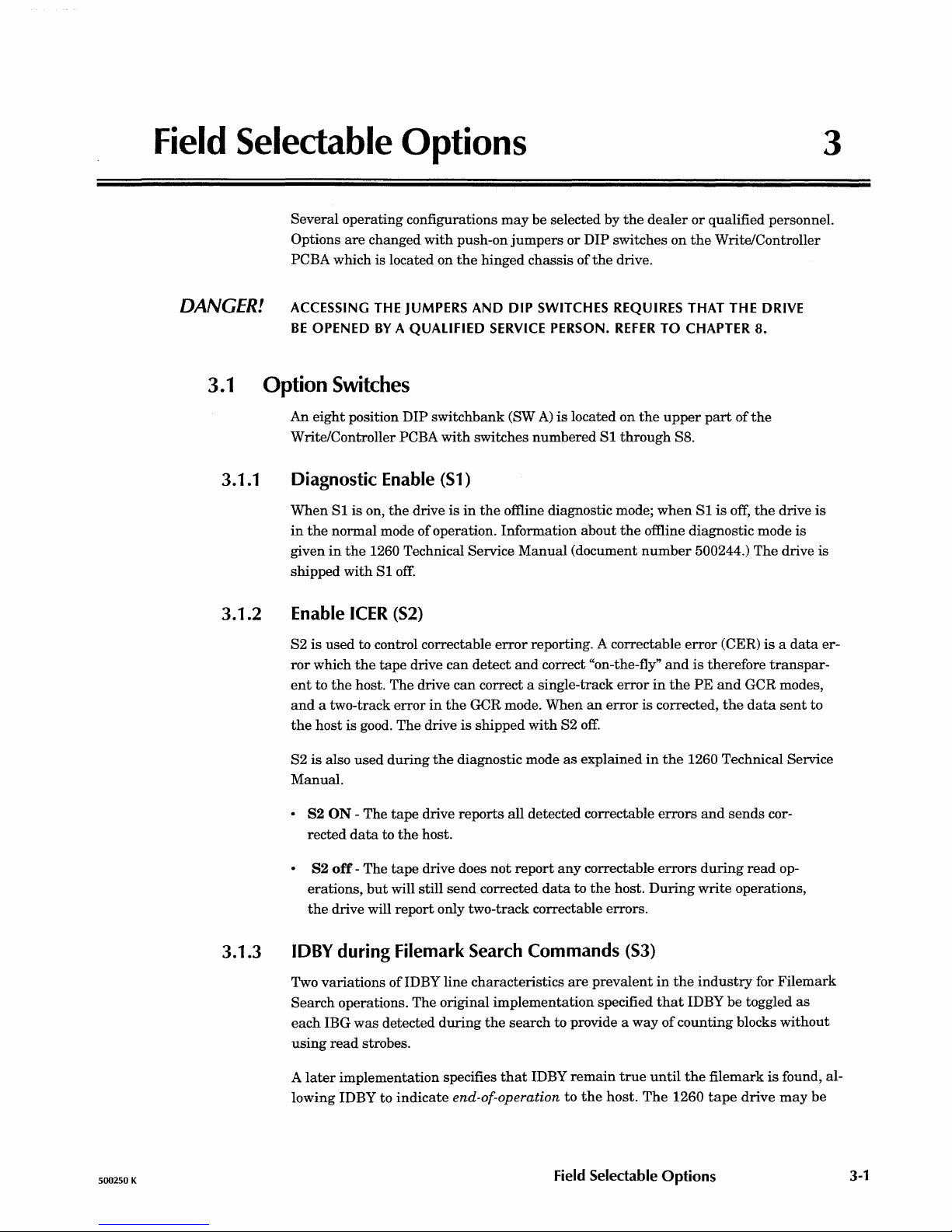
(see Table 3-1.)
The
drive
is
shipped
with
S3 off.
I
S3
I
On
Off
(Factory default)
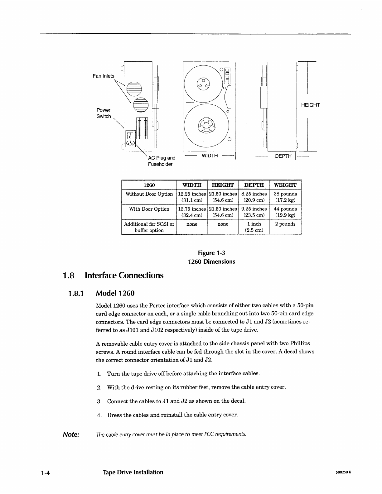
Filemark Gap Length (S4)
IDBY TOGGLES IMPLEMENTATION
At
each
IBG
Only
after
FMK
found
Table
3-1
IDBY/Filemark
Search
Options
Original
Later
The
early
ANSI
standards
specify a leading
gap
of
3.5 inches for filemarks, followed
by
the
standard
IBG
CO.3
inch for GCR
and
0.6 inch for PE.)
Newer
revisions
of
the
standards
no longer
require
the
space-wasting 3.5
inch
leading gaps.
The
1260
tape
drive provides a
tape-saving
option
of
writing
standard
IBG-Iength
leading
gaps.
This
feature
is
selected
by
setting
S4 ON,
saving
approximately 3 inches
of
tape
for
each
file
mark
written.
Depending upon
the
tape
format,
this
can
result
in a substantial
in-
crease
in
formatted
tape
capacity.
The
drive is shipped
with
S4
off.
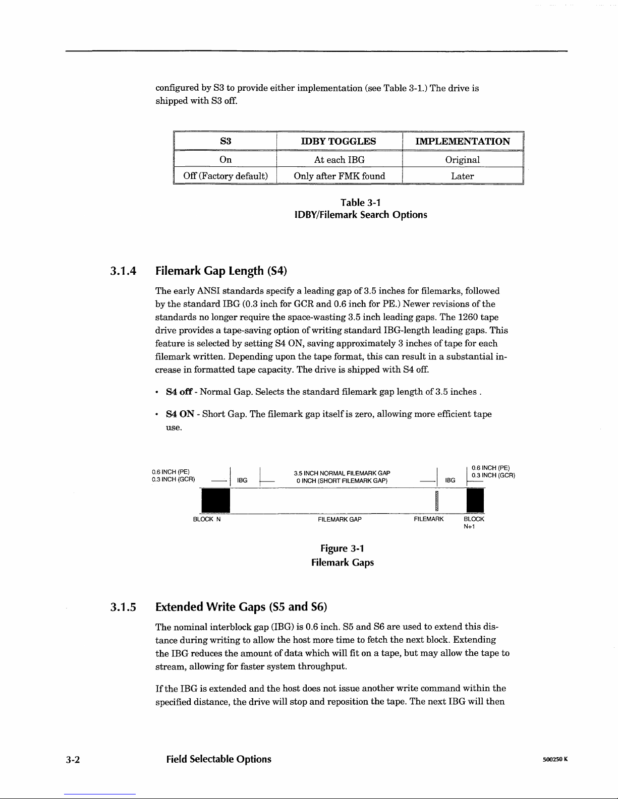
·
S4
off
-
Normal
Gap. Selects
the
standard
filemark
gap
length
of
3.5
inches.
• S4 ON -
Short
Gap. The filemark
gap
itself
is zero, allowing more efficient
tape
use.
0.6
INCH
(PE)
0.3
INCH
(GCR)
3.5
INCH
NORMAL FILEMARK
GAP
03
INCH
(GCR)
I
~
I
~
.6INCH
(PE)
-
IBG
0
INCH
(SHORT FILEMARK
GAP)
-
IBG
.
~--~------------------------------~-----
BLOCK
N
FILEMARK
GAP
Figure
3-1
Filemark
Gaps
Extended
Write
Gaps
(S5
and
S6)
I
FILEMARK
BLOCK
N+1
The
nominal interblock
gap
(IBG) is 0.6 inch. S5
and
S6
are
used
to
extend
this
dis-
tance
during
writing
to allow
the
host
more
time
to fetch
the
next
block.
Extending
the
IBG reduces
the
amount
of
data
which will fit on a tape,
but
may
allow
the
tape
to
stream,
allowing for
faster
system
throughput.
If
the
IBG is
extended
and
the
host
does
not
issue
another
write
command
within
the
specified distance,
the
drive will
stop
and
reposition
the
tape.
The
next
IBG will
then
Field
Selectable
Options
500250 K
 Loading...