

Page 1

GMC200
Media Converter System
User Guide
November 20, 2007
Version: 4.00
Quality Fiber and RF, Inc.
Page 2

GMC200 Media Converter System User Guide
Copyright Notice:
No part of this document may be reproduced, transmitted, transcribed,
stored in a retrieval system, or translated into any language, in any form or by
any means, electronic, mechanical, magnetic, optical, chemical, manual or
otherwise without the prior written permission Quality Fiber and RF, Inc.
i
Page 3

GMC200 Media Converter System User Guide
Disclaimer Notice:
No license is granted, implied or otherwise, under any patent or patent
rights of Quality Fiber and RF, Inc or its partners. Quality Fiber and RF, Inc.
makes no warranties, implied or otherwise, in regard to this document and to
the products described in this document. The information provided by this
document is believed to be accurate and reliable to the publication date of this
document. However, Quality Fiber and RF, Inc. assumes no responsibility for
any errors in this document. Furthermore Quality Fiber and RF, Inc. assumes
no responsibility for the use or misuse of the information in this document and
for any patent infringements that may arise from the use of this document.
The information and product specifications within this document are subject to
change at any time, without notice and without obligation to notify any person
of such change.
ii
Page 4

GMC200 Media Converter System User Guide
Reversion History
Reversion Date Reason for change By
V1.00 Oct. 19, 2006 First draft release FMC
V1.10 Nov. 27, 2006 Some title reworded FMC
V1.20 Nov. 29, 2006 SNMP monitor added FMC
V1.30 Dec. 19, 2006 Web-based management
page re-organized and
added some more details
V1.31 Dec. 23, 2006 Loop back test section re-
organized
V1.40 Jan. 15, 2007 Switchover protection and
http TFTP firmware update
functions added
V2.00 Mar. 22, 2007 SNMP and management
page modified
V3.00 May 22, 2007 Bandwidth / rate control
granularity changed from
32K to 128k.
LED for the converter
redefined.
Telnet function added
V3.10 July 12, 2007 Added optical transceiver
specifications
V3.20 July 12, 2007 Added drawing for the single
fiber converter
V4.00 July 20, 2007 Added IP ping, dual RJ-45
port, OAPS media converter
modules
FMC
FMC
FMC
FMC
FMC
FMC
FMC
iii
Page 5

GMC200 Media Converter System User Guide
Table of Contents
1 Overview .............................................................................................1
1.1 Audience.................................................................................1
1.2 Features..................................................................................1
1.3 Specifications.......................................................................... 2
1.3.1 Optical Specification...................................................2
1.3.2 10/100/1000BASE-T Electrical Specifications ............2
1.3.3 In-band OAM Features...............................................2
1.3.4 IP Ping Features......................................................... 3
2 Hardware Descriptions ........................................................................4
2.1 Carrier Center Chassis ...........................................................4
2.1.1 Front Panel LEDs .......................................................4
2.1.2 Rear Panel Power Supply Slots & Fans .....................6
2.1.3 Rear Panel Management Connectors ........................6
2.1.4 Physical and Environmental .......................................7
2.2 Remote Converter Unit ...........................................................7
2.2.1 Rear Panel Connector................................................8
2.2.2 Physical and Environmental .......................................8
2.3 Network Management Card .................................................... 8
2.4 Plug-in Media Converter Cards............................................... 9
2.4.1 LEDs on the plug-in 100Base-FX Converter Card....10
2.4.2 100Base-FX Optical Port Specifications...................12
2.4.3 1000Base-X Optical Port Specifications...................13
3 Web-based Management ..................................................................14
3.1 System Information ...............................................................15
3.2 Select Chassis ......................................................................16
3.3 Chassis Information ..............................................................17
3.3.1 Chassis Details......................................................... 17
3.3.2 Converter Location ...................................................18
3.3.3 Converter Details...................................................... 19
3.3.4 Converter Status and Configuration .........................20
3.3.5 MIB Counters ...........................................................22
3.4 SNMP Configurations ...........................................................23
3.4.1 SNMP Configurations...............................................23
3.4.2 SNMP Trap Configuration ........................................24
3.5 Network Settings...................................................................25
3.6 TFTP Utilities ........................................................................ 26
3.7 Other Utilities ........................................................................ 27
3.7.1 Alarm........................................................................27
3.7.2 Real-Time Clock.......................................................28
3.7.3 User Account Settings..............................................29
3.7.4 Serial Port Settings................................................... 31
3.7.5 Loopback Testing .....................................................32
3.8 Restart Chassis.....................................................................35
4 SNMP Monitor ................................................................................... 37
4.1 Software Installation..............................................................37
4.2 MIB Brower Usages ..............................................................39
5 Command Line Interface (CLI) ..........................................................43
5.1 Main Command Menu...........................................................43
iv
Page 6

GMC200 Media Converter System User Guide
5.2 System Information ...............................................................44
5.3 Card Commands...................................................................44
5.4 Select a Chassis ...................................................................49
5.5 Network Information..............................................................50
5.6 SNMP ...................................................................................50
5.7 Alarm ....................................................................................51
5.8 Set System Information.........................................................52
5.9 Retime System Clock............................................................52
5.10 Reset Command ................................................................... 53
5.11 Reboot Command.................................................................53
v
Page 7

GMC200 Media Converter System User Guide
1 Overview
The GMC200 is a high performance, cost effective, carrier grade
manageable media converter system, which is intended for applications of the
point-to-point fiber-to-the-premises (FTTx) market.
The GMC200 platform offers 100BASE-FX to 10/100BASE-TX conversion
or 1000BASE-X to 10/100/1000BASE-TX conversion or other media and
protocol conversion in the future releases.
The GMC200 provides remote loopback and in-band TS-1000 OAM
capabilities to manage subscriber access network from carrier center side to
terminal side, while the embedded management software allows
administrators to easily configure features, monitor performance, and
troubleshoot the system using command line interface, standard Web browser
and Simple Network Management Protocol (SNMP) based network
management platforms.
1.1 Audience
This guide is intended for network installers and system administrators
who are responsible for installing, configuring, or maintaining networks. This
guide assumes that you understand the transmission and management
protocols used on your network.
1.2 Features
• Each chassis containing up to 15 media converter (MC) slots plus
one network management card (NMC) slot
• Up to 4 chassis managed by a single management unit with one
master management card plus three slave management cards
• In-band network management (OAM) communication with TS-1000
standard to manage subscriber access network from carrier center
side to terminal side.
• 10/100Base-TX to 100Base-FX media conversion
• 10/100/1000Base-TX to 1000Base-X media conversion
• Single fiber to dual fibers conversion
• Multi-mode fiber to single mode fiber conversion
• Non-blocking store-and-forward architecture enables the
forwarding rate to proceed at a full wire speed
• 802.3x flow control for a full-duplex mode and collision-based
backpressure for a half-duplex mode
• Egress/Ingress rate management control with 128Kbps granularity
• Optional automatic converter switchover protection
• Programmable remote fault detection (RFD) function
• Remote power on / off detection with dying gasp alarm
• Remote loopback capability for link integrity test
1
Page 8

GMC200 Media Converter System User Guide
• Dual processor management card for maximize the system
performances
• Dual power supply of load sharing or 1 + 1 automatic over features
with over-voltage / under-voltage alarms
• Dual fans with monitoring and alarm features
• Standard 19 inch rack mounted.
1.3 Specifications
1.3.1 Optical Specification
Interface Type: 1000Base-LX /SX
¾ Dual multimode fiber (50/125μm), single wavelength 850nm, dual
SC or LC connectors, operating distance 550m.
¾ Dual multimode fiber (62.5/125μm), single wavelength 850nm,
dual SC or LC connectors, operating distance 275m.
¾ Dual single-mode fiber, single wavelength 1310nm or 1550nm,
dual SC or LC connectors, operating distance 15/40km.
Interface Type: 100Base-FX
¾ Single single-mode fiber, dual wavelength 1310 / 1550nm, SC
connector, operating distance 20/ 30 / 50 km.
¾ Dual single-mode fibers, single wavelength 1310 or 1550nm, SC
connector, operating distance 20 / 30 / 50km.
¾ Dual multi-mode fibers, single wavelength 1310nm, SC connector,
operating distance 2km.
1.3.2 10/100/1000BASE-T Electrical Specifications
• Speed: 10/100/1000Mbps with Auto-negotiation capability
• Distance: 100 meters
• Duplex: Full/Half duplex
• Cable: UTP 5
• Connector: RJ45
• Interface Type: 10/100/1000BASE-TX
• Automatic MDI / MDI-X cross-over for straight-through or crossover
CAT5 cable
1.3.3 In-band OAM Features
• Supports OAM sub-layer which confirms to TS-1000 specification from
TTC (Telecommunication Technology Committee).
• Remote converter configuration and status monitoring using in-band
OAM frame and not consuming any IP resource and link bandwidth.
• Sends and receives OAM frames to center or remote side.
• Loopback mode to support loopback packet from center side to remote
side.
2
Page 9

GMC200 Media Converter System User Guide
• Far-end fault detection with disable and enable options.
• Link transparency to indicate the link down from link partner.
1.3.4 IP Ping Features
In addition to the in-band OAM features, GMC200 media converter
system also supports IP ping function on some MC units, which allows the
network manager to monitor the remote media converter at IP level.
3
Page 10
GMC200 Media Converter System User Guide
2 Hardware Descriptions
2.1 Carrier Center Chassis
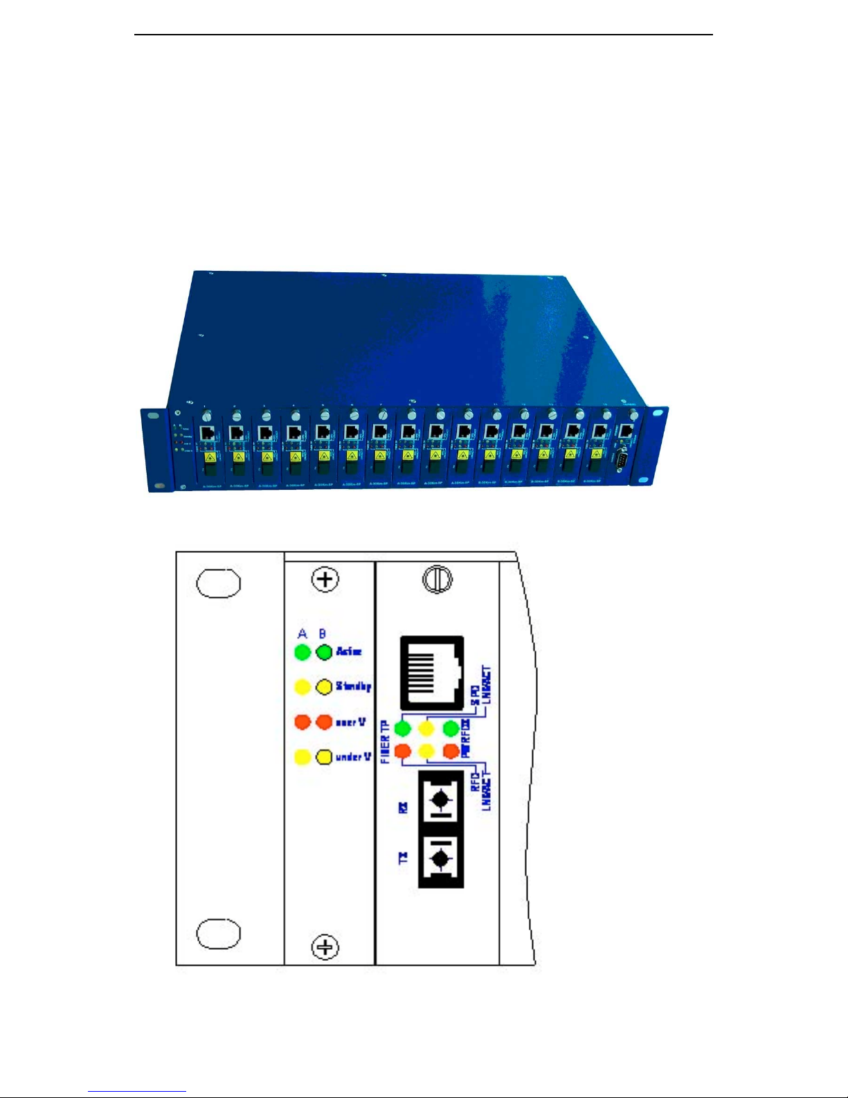
The GMC200 media converter system’s carrier center chassis is shown in
the following drawings,
cards and 1 piece of network management card. All plug-in cards are hotswappable.
The whole rack contains 15 pieces of media converter
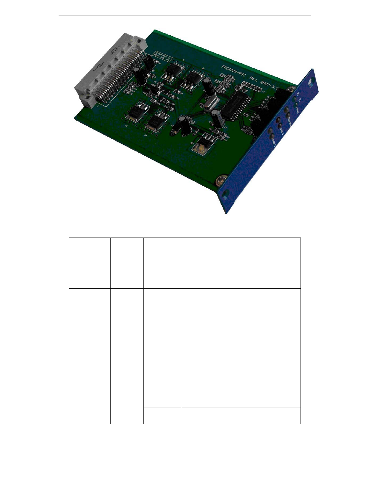
2.1.1 Front Panel LEDs
The front panel power supply status LEDs are shown as below:
4
Page 11
GMC200 Media Converter System User Guide
The following table shows the power supply LED definitions:
Label Color State Definition
Green
On The power is on and supplying the
current to the system.
Active
Off The power is off or in standby
mode. It is not supplying the
current to the system.
Yellow
On The power is on and in standby
mode. It is not supplying the
current to the system. It will supply
Standby
the current to the system
immediately when the active power
is going off.
Off The power supply is off or it is on
and in active mode.
Over V Red
On The output voltage of the power
supply is above 5.5V.
Off The output voltage of the power
supply is below 5.5V or it is off.
Under V Yellow
On The output voltage of the power
supply is below 4.5V.
Off The output voltage of the power
supply is above 4.5V or it is off.
5
Page 12
GMC200 Media Converter System User Guide
2.1.2 Rear Panel Power Supply Slots & Fans
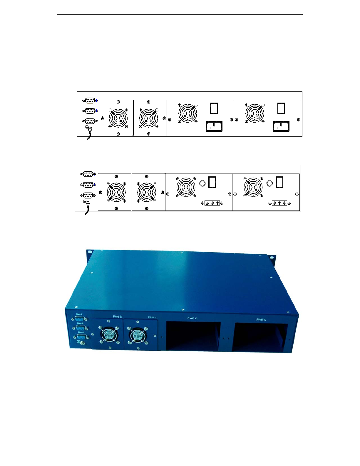
There are two slide-in power supply slots on the rear panel to
accommodate the power supply modules, which are used to support
redundant backup for the chassis. Both power modules can accept either
220VAC or -48VDC supply.
Slave A
Slave B
Slave C
Slave A
Slave B
Slave C
FAN AFAN B
FAN AFAN B
PWR B PWR A
I
O
PWR B PWR A
I
O
I
O
I
FUSEFUSE
O
In addition to the power supply module, two removable / replaceable fans
can be found on the rear panel, which are used to cool down the chassis.
2.1.3 Rear Panel Management Connectors
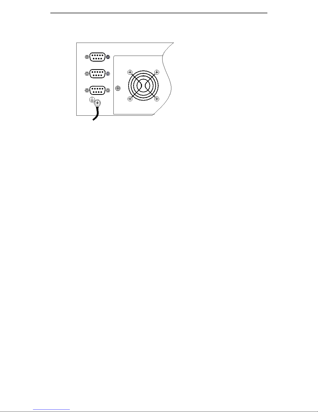
There are also three DB-9 connectors in the rear panel used to connect
the master chassis and the slave chassis for network management
communication. Straight through 9-pin DB9 male cable shall be used in this
application. All three connectors are used on the master chassis, while only
the top DB-9 connector is used for the slave chassis. The location for these
connectors and numbering scheme can be found in the following drawing:
6
Page 13
GMC200 Media Converter System User Guide
Slave A
Slave B
Slave C
2.1.4 Physical and Environmental
• Dimensions: 19-inch rack-mount width, 2.0U height.
• Weight: 9 Kg
• Operating temperature: 0 ~ 65
• Storage temperature: -25 ~ 85
• Humidity: 5% ~ 95% RH Non-condensing
2.2 Remote Converter Unit
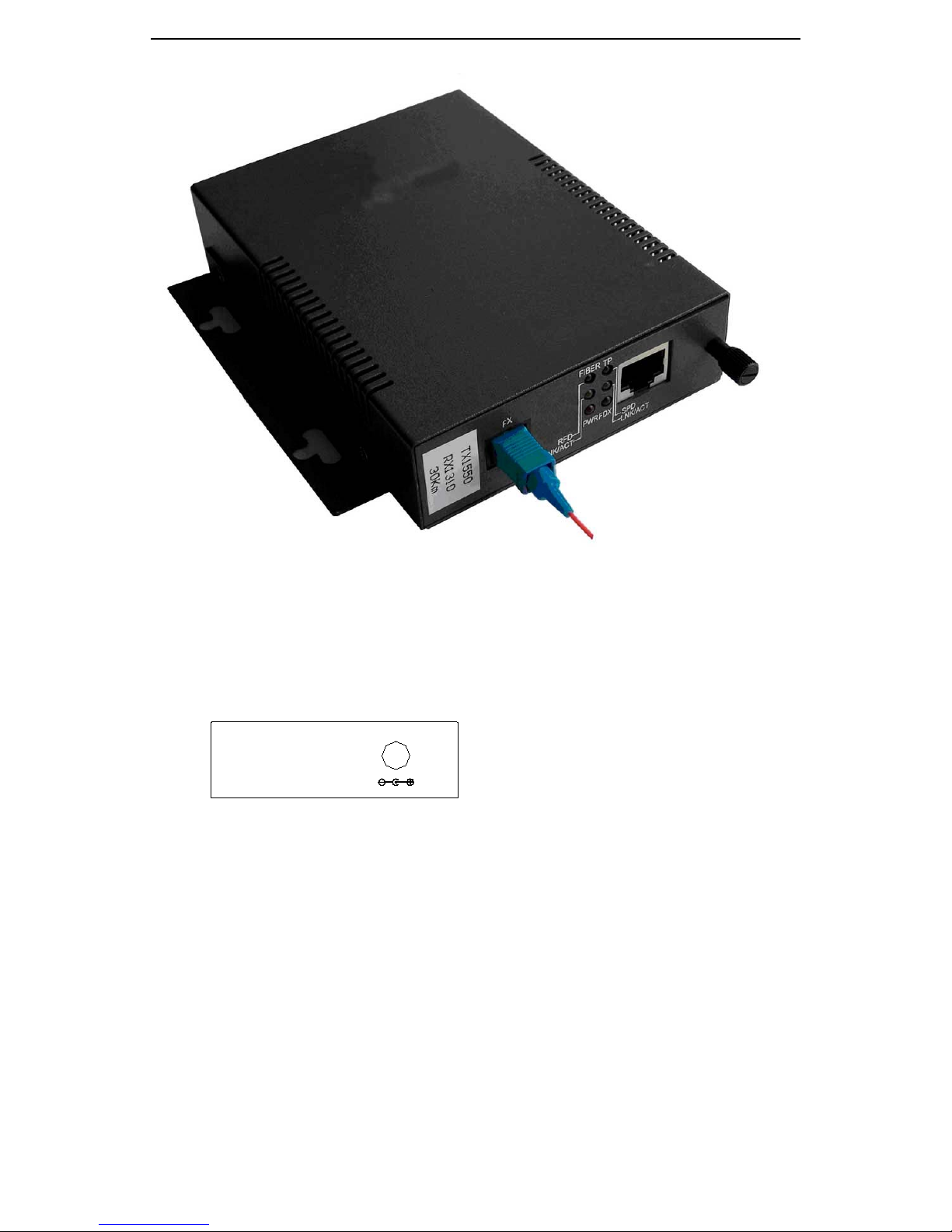
The following drawing is the outline of the remote converter unit. The unit
can be wall-mounted for use in special cases.
7
Page 14
GMC200 Media Converter System User Guide
2.2.1 Rear Panel Connector
The remote converter unit supports 5V DC power supply options. The
following figure shows the power connector on the rear panel.
5VDC
2.2.2 Physical and Environmental
• Dimensions: 125×90×28mm
• Weight: 0.50Kg
• Operating temperature: 0 ~ 65
• Storage temperature: -25 ~ 85
• Humidity: 5% ~ 95% RH Non-condensing
2.3 Network Management Card
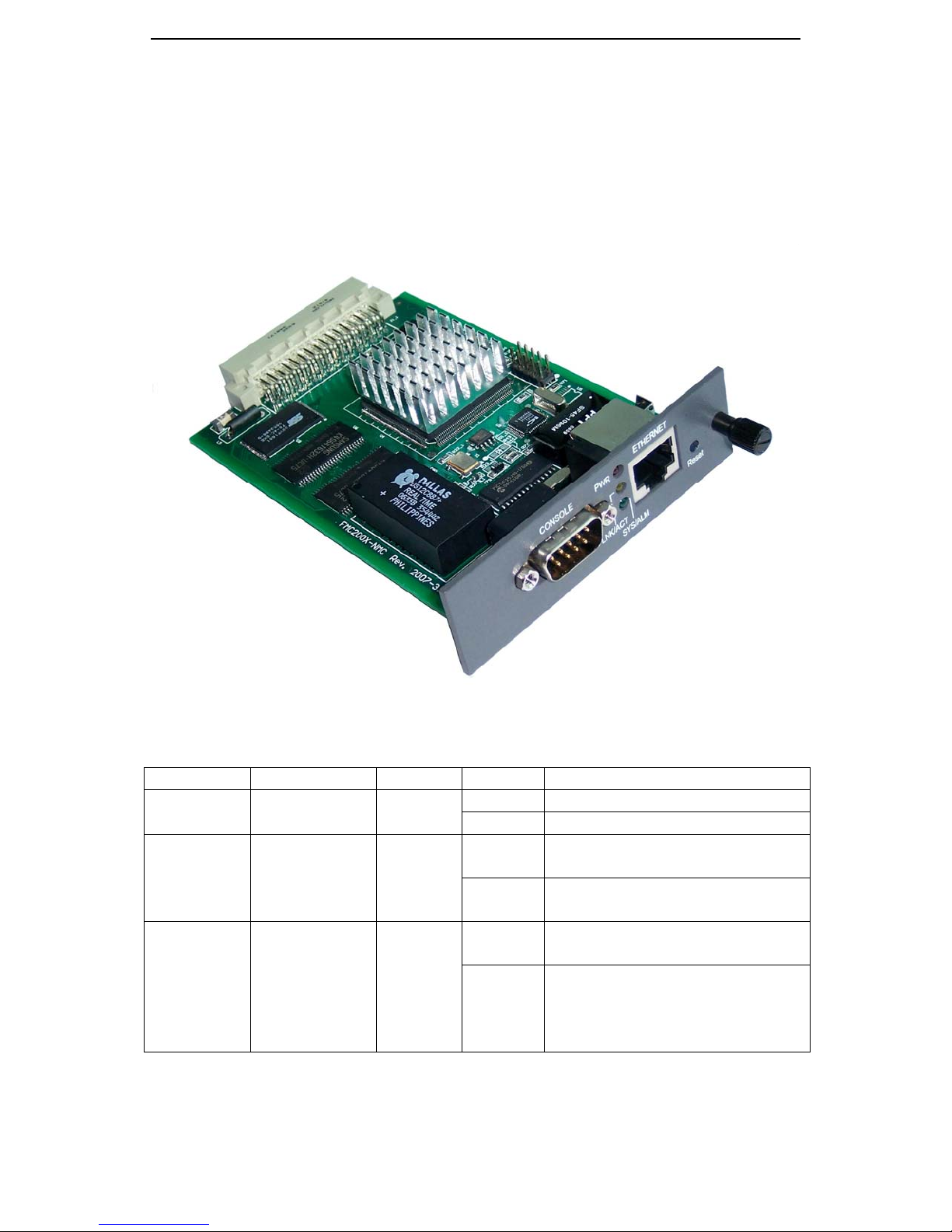
GMC200-NMC network management card (NMC) contents dual
embedded processors to optimize the system performance. The 32-bit RISC
8
Page 15
GMC200 Media Converter System User Guide
base processor is responsible for the network protocol processing, while the
16-bit instruction set MCU is used for the system house keeping, such as the
communication, control and status gathering between the master and slave
chassis, the local and remote converters. The embedded software on the
NMC supports command line interface (CLI) based, Web-based and SNMP
management options to meet your system management requirements at
different levels.
The following table shows the LED descriptions.
Label Type Color State Description
PWR Power status Red
LNK/ACT
RJ45
Yellow
Ethernet link
status
On
Off
On
The converter is power on
The converter is power off
Valid communication link
established at RJ45 port
Blinking Indicates network activity for
the corresponding RJ45 port
SYS/ALM Management
software
status and
alarm
Green
On Management software is in
normal operational
Blinking Management system is
booting up or the software
upgrade is in progress or
there is a software error alarm
2.4 Plug-in Media Converter Cards
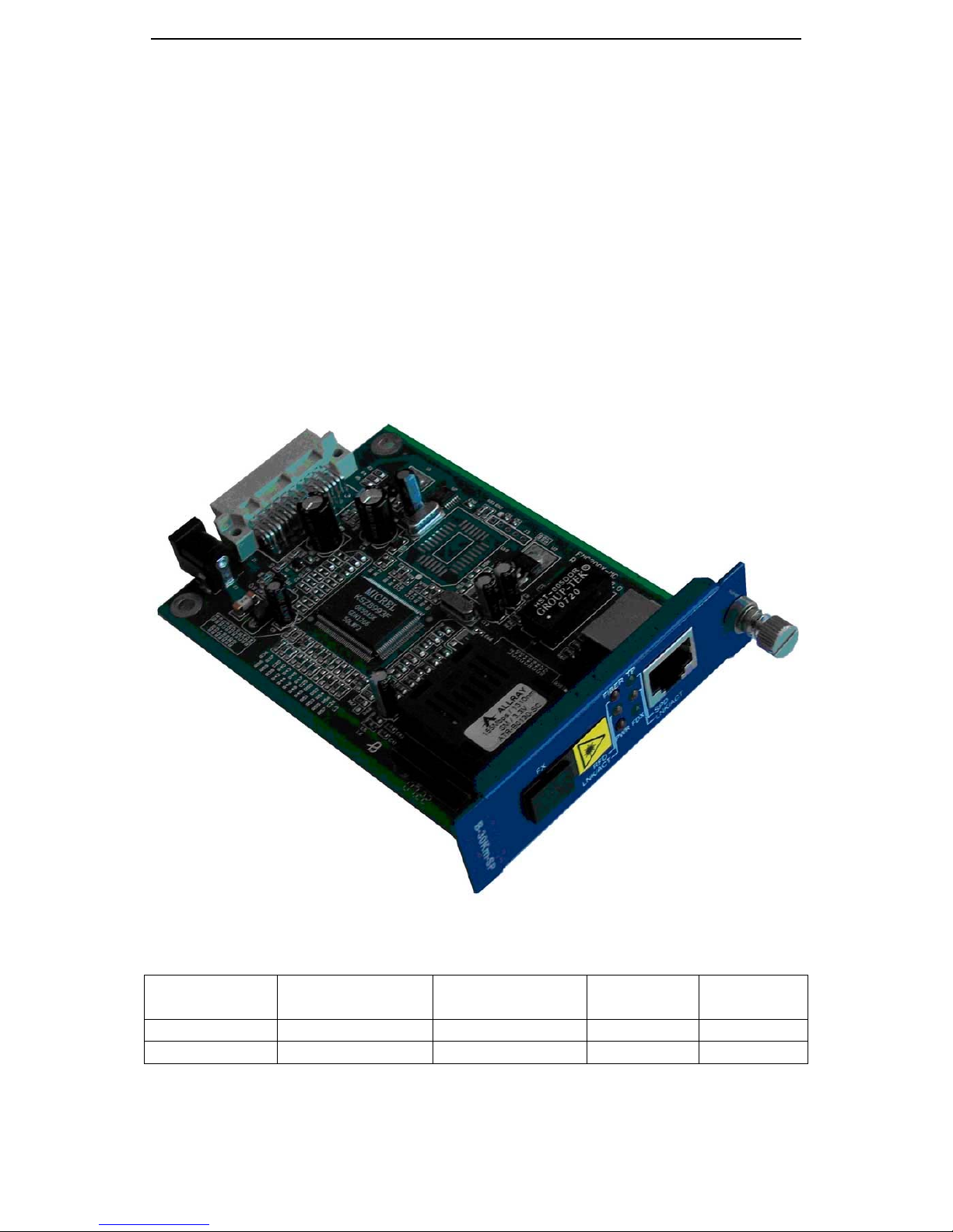
GMC200 system uses the same plug-in card in both carrier center chassis
9
Page 16
GMC200 Media Converter System User Guide
and the remote converter unit. There are different kinds of plug-in converter
cards for different applications, such as
• 10/100Base-TX to multi-mode 100 Base-FX converter card with or
without IP ping function
• 10/100Base-TX to single mode dual fiber 100 Base-FX converter
card with or without IP ping function
• 10/100Base-TX to single mode single fiber 100 Base-FX converter
card with or without IP ping function
• Multi-mode 1000Base-SX to single mode 1000 Base-LX converter
card without IP ping,
• 10/100/1000Base-TX to single mode single or dual fiber 1000
Base-LX converter card with or without IP ping.
The picture of a media converter card is shown below.
The following table summarizes the available plug-in media converter
cards:
Card Type Local Interface WAN Interface
GMC200C 1 x 10/100BT 1 x 100FX Yes No
GMC200C-P 1 x 10/100BT 1 x 100FX Yes Yes
2.4.1 LEDs on the plug-in 100Base-FX Converter Card
10
In-band
OAM
IP Ping
Page 17

GMC200 Media Converter System User Guide
There are six diagnostic and status LEDs on the face panel of media
converter card, which are used as the indications of power, optical and UTP
ports. As mentioned before, the media converter plug-in card is hot
swappable. The card also offers power down and up detection features (dying
gasp), which will automatic send the power down or power up alarm to the
network management system via in-band OAM frame, if the power supply
voltage drops to dangerous level or comes back to normal level. The following
table shows the LED descriptions.
Label Type Color State Description
PWR Power status Red
TP/SPD
Speed
Yellow
Indicator
On
Off
On
The converter is power on
The converter is power off
The converter is in 100BASETX mode
Off The converter is in 10BASE-
TX mode
TP/FDX Full-duplex/
half duplex
Indicator
Yellow
On The 10/100BASE-TX port is
in full duplex mode
Off The 10/100BASE-TX port is
in half duplex mode
RFD
Remote
Failure
Red
On
Off The RFD function is disabled
The RFD function is enabled
Detection
TP
/LNK/ACT
Link status
and Port
activity
Green
On Valid communication link
established
Blinking Indicates network activity for
the corresponding port
Off The link condition is poor or
there is no connection to this
port
Fiber
LNK/ACT
Link status
and Port
activity
Green
On Valid communication link
established
Blinking Indicates network activity for
the corresponding port
Off The link condition is poor or
there is no connection to this
port
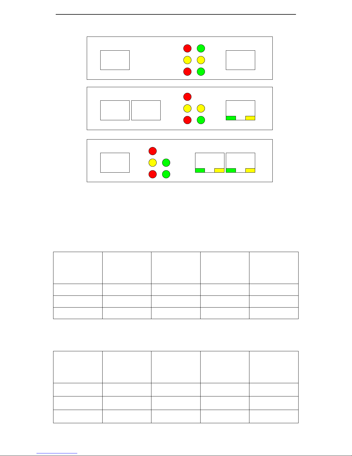
The following figure shows the LED assignments for all available 100
Base-FX converter types.
11
Page 18
GMC200 Media Converter System User Guide
Standard M C
P1-FX P2-TX
APS MC
P1-FX P2-TX
Dual TX MC
P3-FX
RFD
P1-FX P3-TX P2-TX
PWD
RFD
LNK/ACT1
PWD
RFD
LNK/ACT1
PWD
FDX3LNK/ACT1
FDX2
SPD2
LNK/ACT2
FDX2
LNK/ACT3
FDX2
LNK/ACT3 LNK/ACT2SPD3 SPD2
LNK/ACT2SPD2
2.4.2 100Base-FX Optical Port Specifications
The optical port specifications for the 100 Base-FX plug-in converter card
at the central side are listed in the following table.
Optical
Output
Wavelength
(nm)
Optical
Output
Wavelength
(nm)
Spectral
Width (nm)
Spectral
Width (nm)
Transmission
Distance (km)
Optical
Output Power
(dBm)
Receiving
Sensitivity
(dBm)
20 -14 ~ -7 -32 1550 < 4
30 -10 ~ -3 -33 1550 < 4
50 -8 ~ -3 -36 1550 < 1
The optical port specifications for the 100 Base-FX plug-in converter card
at the remote side are listed in the following table.
Transmission
Distance (km)
Optical
Output Power
(dBm)
Receiving
Sensitivity
(dBm)
20 -14 ~ -7 -32 1310 < 4
30 -10 ~ -3 -33 1310 < 4
50 -5 ~ 0 -36 1310 < 4
12
Page 19

GMC200 Media Converter System User Guide
2.4.3 1000Base-X Optical Port Specifications
As the SFP module is used in the 1000Base-X media converter cards,
regarding the 1000Base-X optical port specifications, please refer to the
datasheet of the SFP module used.
13
Page 20
GMC200 Media Converter System User Guide
3 Web-based Management
The Web-based management interface is one of many tools specifically
designed to assist the network manager in creating complex standalone or
network configurations.
This guide describes how to use the Web-based management interface to
configure and maintain your GMC200 media converter system. It is intended
for network managers who are responsible for configuring the system. This
guide assumes prior knowledge and understanding of the terminology,
theories, and practices and specific knowledge about the networking devices,
protocols, and interfaces that comprise your network.
You should have working knowledge of the Microsoft* Windows*
operating system, graphical user interfaces (GUIs), and Web browsers.
GMC200 provides the default network settings for the Web browsers as
follows. It offers three different login privileges: superuser, admin and guest.
You can change the following parameters at any time after you have
successful logged into the system.
• IP Address: 192.168.223.100
• Subnet Mask: 255.255.248.0
• Default Gateway: 192.168.223.254
• User Name: superuser
• Password: 1235678
• User Name: admin
• Password: 123
• User Name: guest
• Password: 123
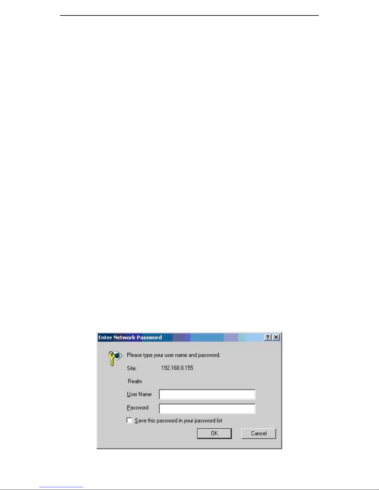
You can browse http://192.168.223.100, type user name and password as
above, if you have not made any change to the network setting.
14
Page 21
GMC200 Media Converter System User Guide
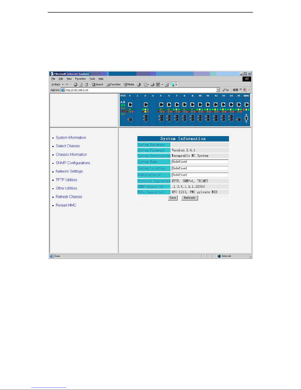
After you type the correct user name and password in the window shown
above, you will see the following homepage for the system. It is important to
note that GMC200 management system will not automatic log out even if the
webpage stays inactive for a period of time. You shall close the page if you
think it is necessary.
3.1 System Information
The system information page allows you to add the system name, location
and the system administrator contact information to management data base.
The information gives the network administrator a simple way to trace and
manage the systems in the field.
15
Page 22
GMC200 Media Converter System User Guide
3.2 Select Chassis
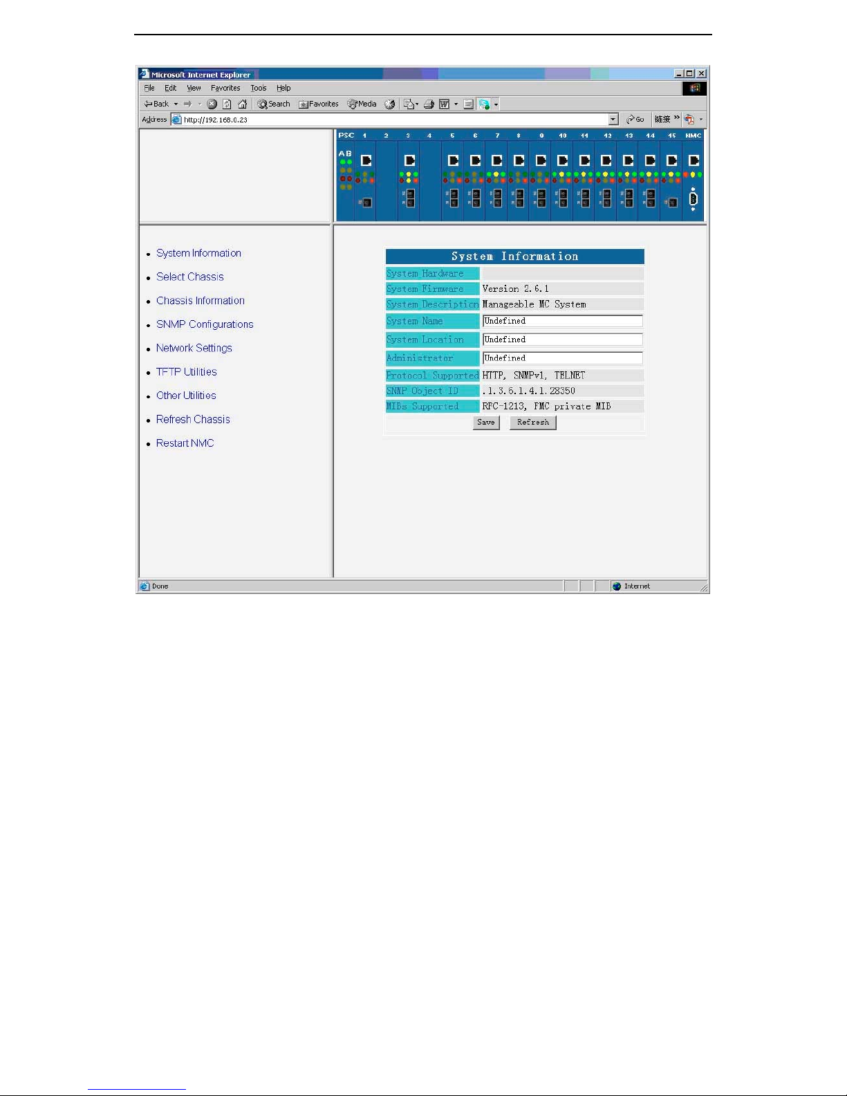
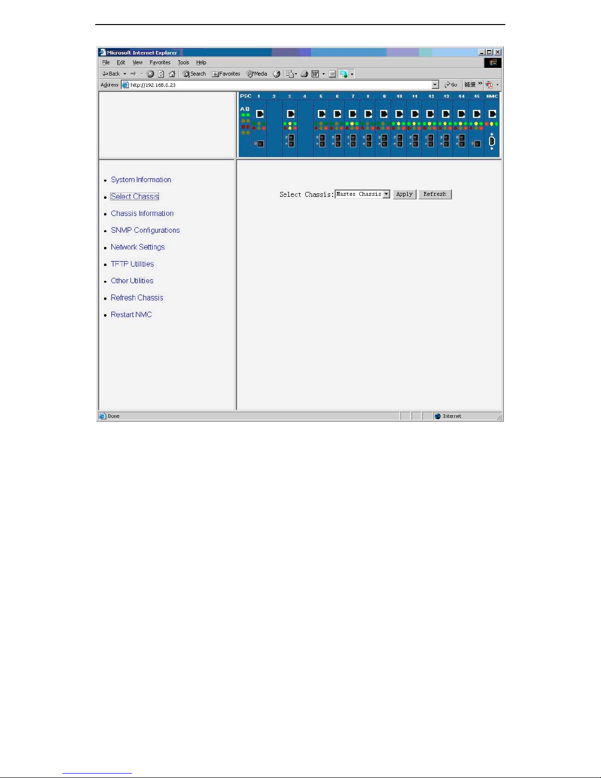
As a single GMC200 network management unit can manage up to 4
chassis, you shall select a chassis to be managed and monitored prior to any
operation. The following figure shows that all the four chassis are connected
and are powered. Here the “master” refers to the chassis with RJ45 and DB9
connecter on the front panel of the network management card, which is
connected to the management terminal via Ethernet connection. While the
“slave1”, “slave2” and “slave3” are the chassis connected via the DB9 cable
on the rear panel of the master chassis.
It is important to note that if a slave chassis is not connected or power off,
it will not appear on the selection tab as shown in the following figure.
16
Page 23
GMC200 Media Converter System User Guide
3.3 Chassis Information
There are four functional items under the “Chassis Information” tab. They
are:
• Chassis Details
• Converter Location, and
• Converter Details.
You can display all the chassis related information and configure the local
and remote converter parameters here.
3.3.1 Chassis Details
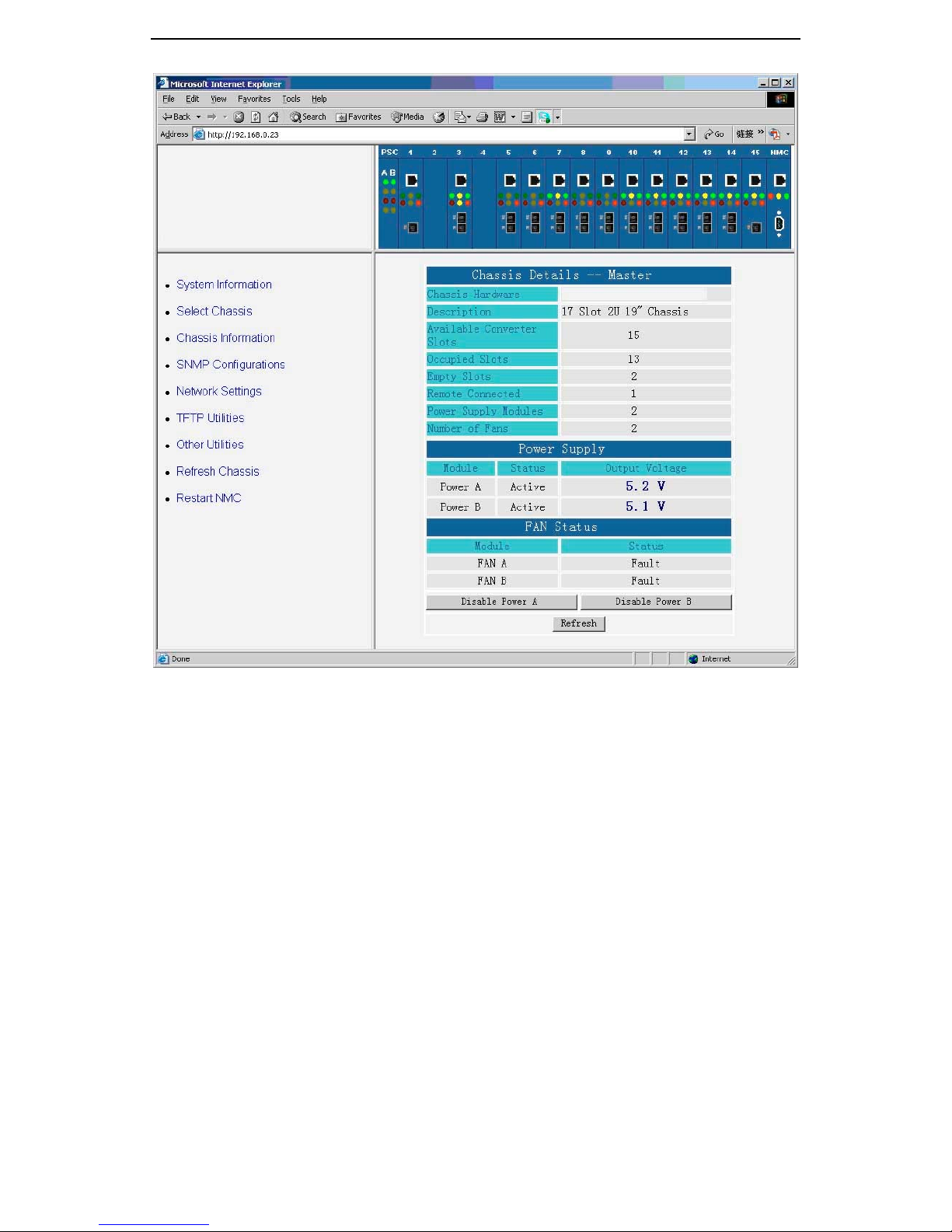
The chassis detail information will be shown as below after you click the
web page “Chassis Details” under the “Chassis Information” tab. The chassis
details page will show all the basic information for the selected chassis, such
as the slot occupancies, power supply and fan conditions.
17
Page 24
GMC200 Media Converter System User Guide
3.3.2 Converter Location
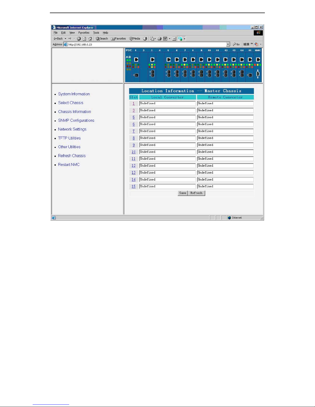
The local and remote converter locations can be defined in the following
web page. The information could be used to identify the converter. You can
put the customers name or location here.
18
Page 25
GMC200 Media Converter System User Guide
3.3.3 Converter Details
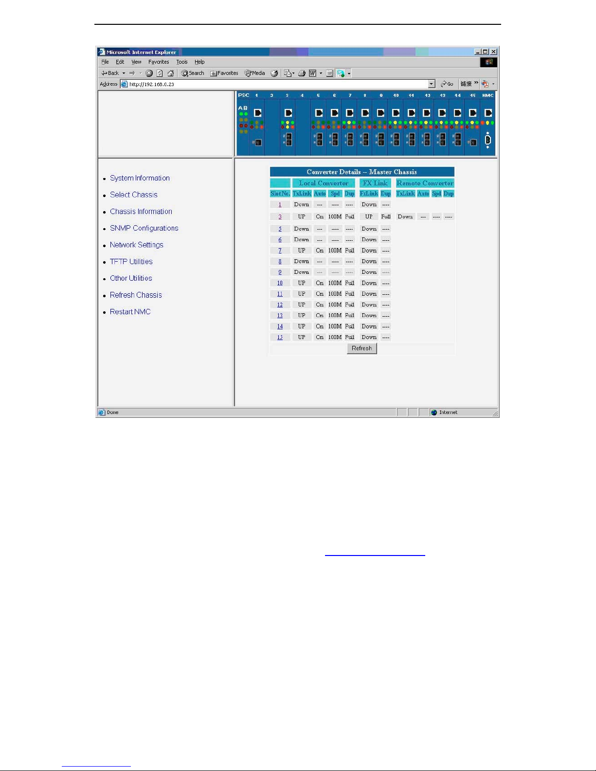
The following screen capture shows the port status for the selected
chassis. The management software will only show the slot status with a plugin in it. If the remote converter is not connected or powered off, its status will
not show on the page. Each number in the “Slot No.” column is linked to the
converter status, configuration and control page.
19
Page 26
GMC200 Media Converter System User Guide
3.3.4 Converter Status and Configuration
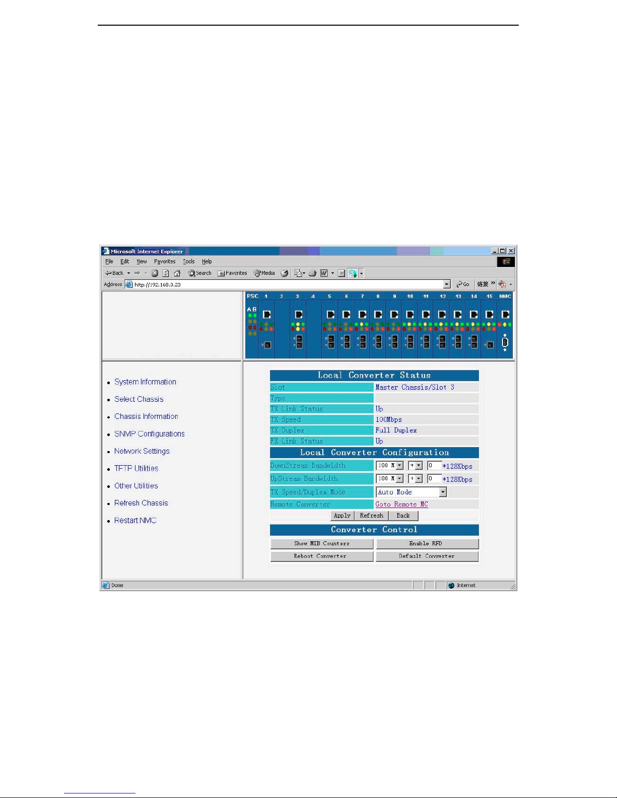
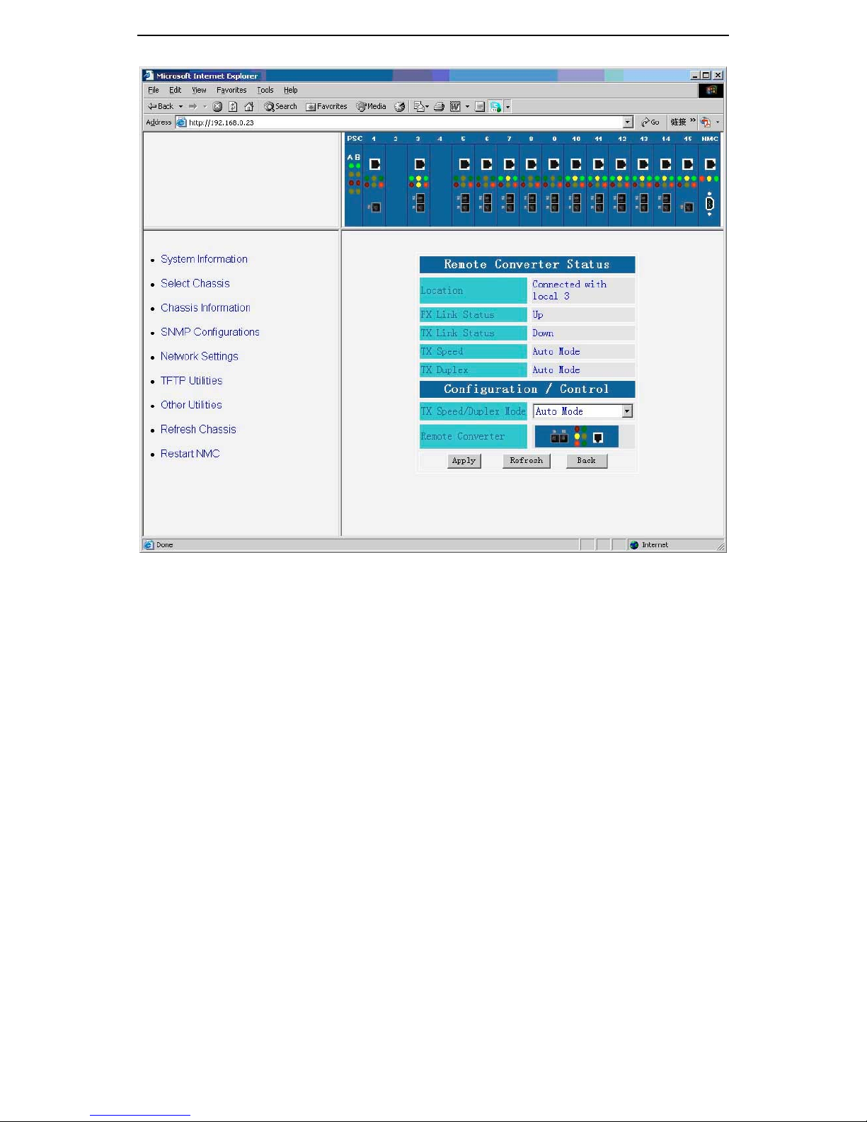
You can browse the converter status and configuration page either by
clicking the number shown in the “Slot No.” column of “Converter Details”
page as above, or direct clicking the converter shown in the chassis graphic.
The following screen capture shows the local and remote converters’ detail
and configuration items, respectively. You can also browse to the “Remote
Converter Detail” page by clicking the “Goto Remote MC” link on the
“Converter Detail” page. The followings are the control tabs used on these two
pages.
• Upstream / Downstream Bandwidth: You can enable the rate
control at 128 Kbps step on both directions. The valid range is 0 ~
100M. When the number is set to 100M, the bandwidth limitation
function will be disabled.
• Tx Speed / Duplex Mode: Allows you to choose between autonegotiation, 100Mbps or 10Mbps and half or full duplex modes.
When Auto-mode is selected, auto negotiation is enabled, the link
speed and duplex mode will be automatic set based on the link
condition to offer the highest link performance for the system.
20
Page 27
GMC200 Media Converter System User Guide
• Reboot Converter: When you click the “Reboot Converter” button,
both the local and remote converters will perform software reset,
but all the configurations will be kept.
• Default Converter: When you click the “Default Converter” button,
both the local and remote converters will be reconfigured back to
the factory default.
• Show MIB Counters: Display the content of 32 MIB counters.
• Remote Fault Detection (RFD): The feature allows the remote
converter to show the local converter’s status on its LEDs, or vice
versa. If the RFD is enabled, the remote converter’s TX port LEDs
and transmitter will turn off when the local TX port is down, or the
local converter’s TX port LEDs and transmitter will turn off when the
remote TX port is down.
21
Page 28
GMC200 Media Converter System User Guide
3.3.5 MIB Counters
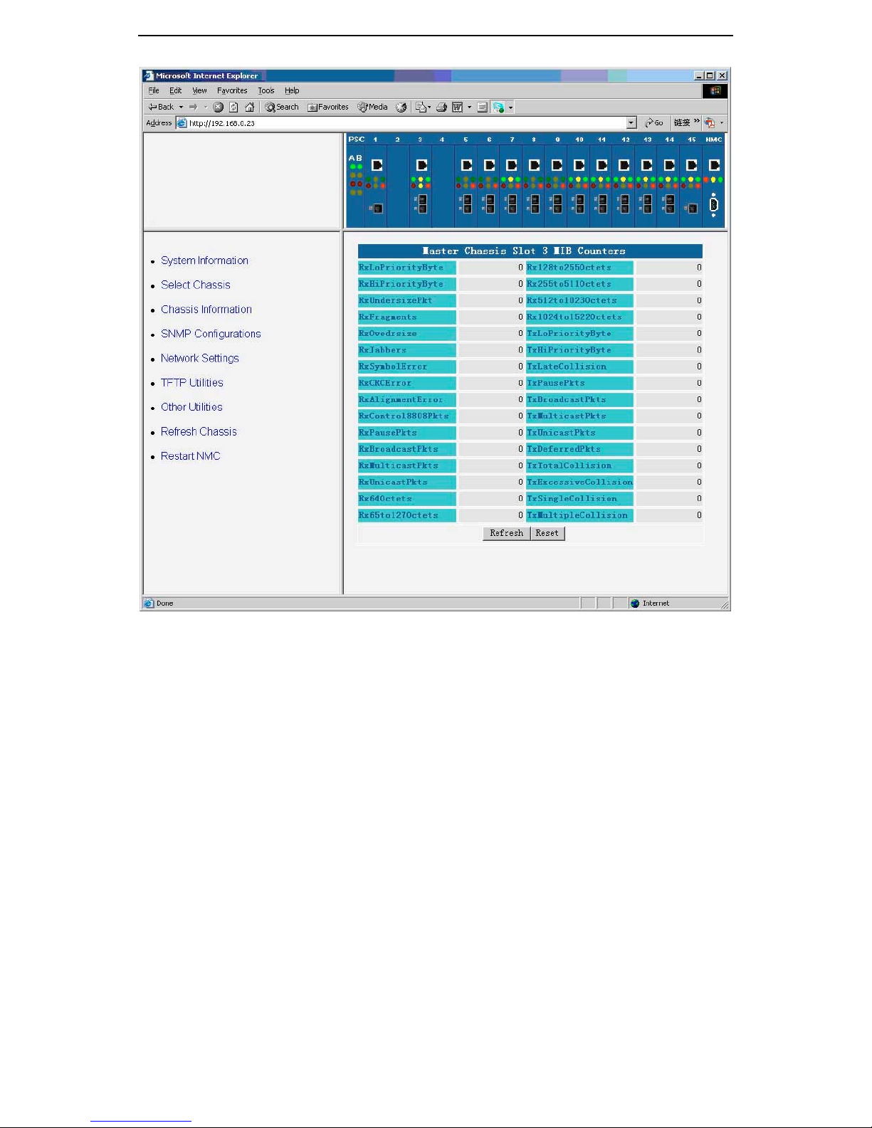
You can show the converter MIB counters by clicking the web page button
of “Show MIB Counters” under the “Local Converter Control” tab. The total of
32 MIB counters will be shown as following web page. All the MIB counters
are 32 bits wide, they will overflow in a period of time.
22
Page 29
GMC200 Media Converter System User Guide
3.4 SNMP Configurations
Simple Network Management Protocol (SNMP) is the standard for
network management that uses a common software agent to manage local
and wide area network equipment from different vendors; part of the
Transmission Control Protocol/Internet Protocol (TCP/IP) suite and defined in
RFC1157. SNMPv1 is version one, or the original standard protocol. GMC200
management system supports SNMPv1.
You can configure SNMPv1 read/write and read-only community strings,
enable or disable trap mode settings.
3.4.1 SNMP Configurations
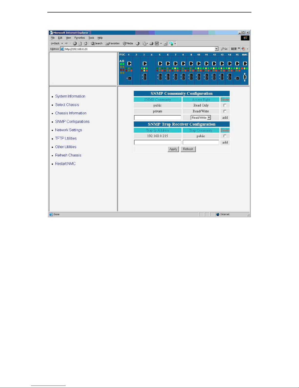
The configuration of the SNMP community string and trap mode can be
shown by clicking “Community Configuration” under the “SNMP
Configurations” page as captured below. You can configure the IP address
and community string for a new SNMP trap receiver, view a table of existing
SNMP trap receiver configurations, or delete an existing SNMP trap receiver
configuration(s).
23
Page 30
GMC200 Media Converter System User Guide
3.4.2 SNMP Trap Configuration
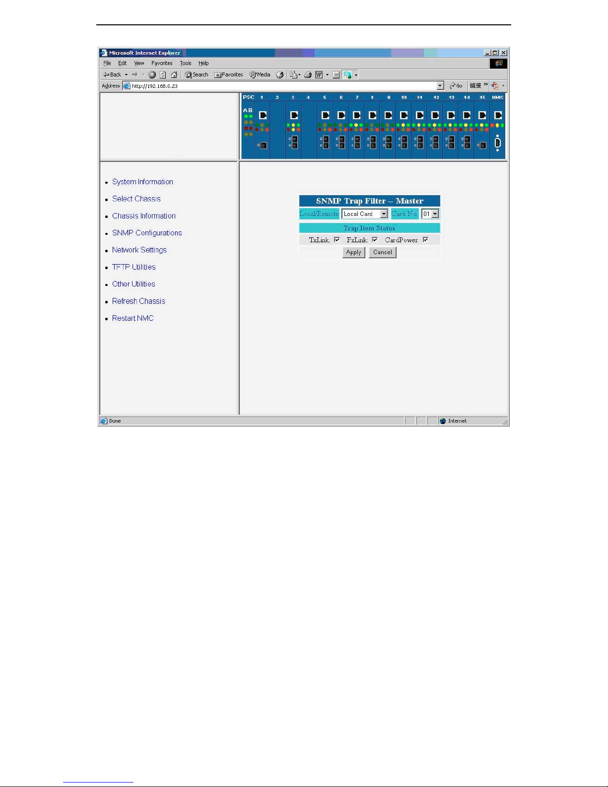
To create SNMP traps, you should open the “Trap Configuration” page
under the “SNMP Configurations” as shown below. First you need to select
where the traps come from, then you can select the trap item status, including
link up and down status and/or power on and off status.
24
Page 31
GMC200 Media Converter System User Guide
3.5 Network Settings
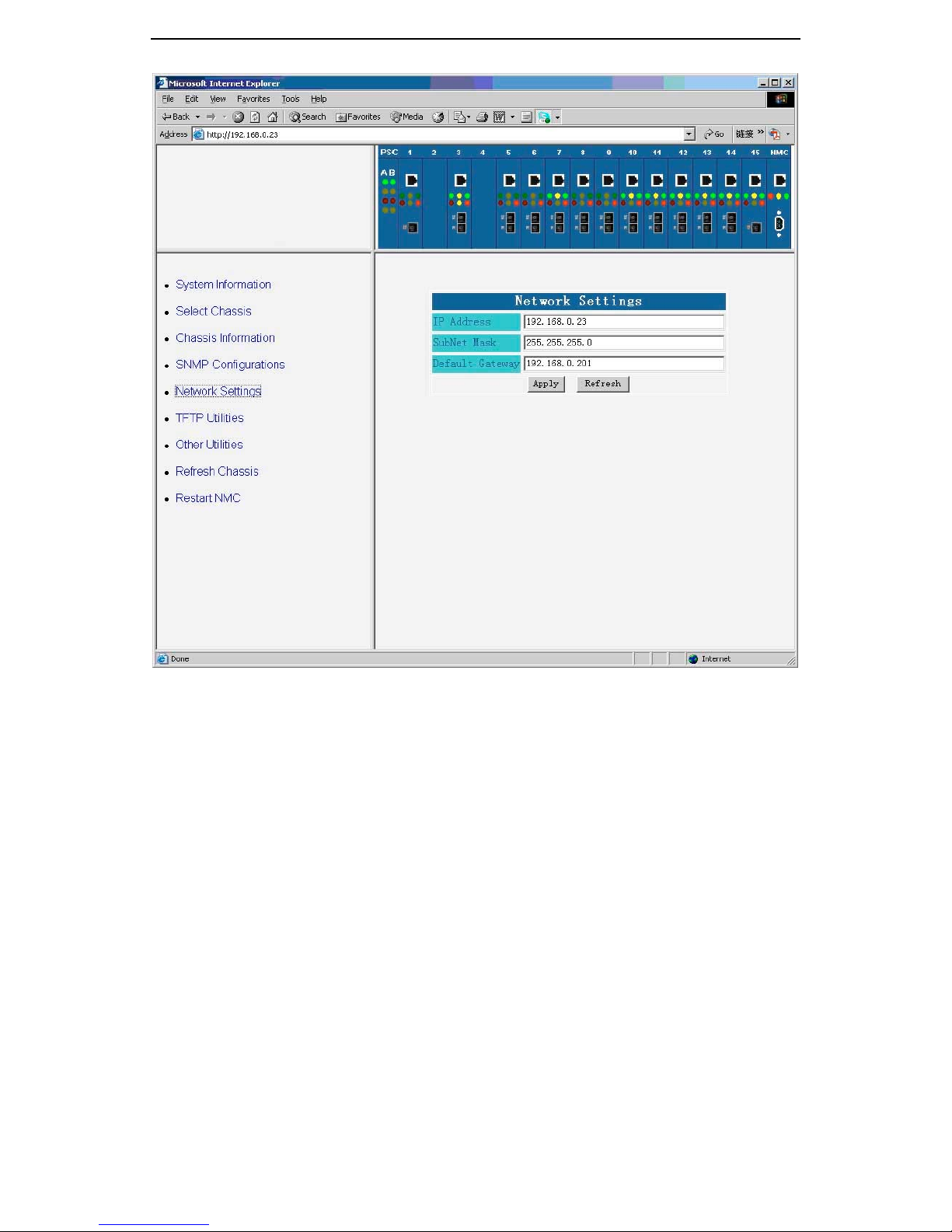
If you want to manage and monitor the GMC200 media converter system
remotely, you must have a proper network setting for the system, which
include the IP address, subnet mask and default gateway as shown in the
following figure. After you have changed the network settings, you shall restart
the chassis in order to bring the new setting into effect.
The network setting for the system can be changed back to the factory
default by pressing and holding the reset button on the face plat of the
network management card for more than 5 seconds.
25
Page 32
GMC200 Media Converter System User Guide
3.6 TFTP Utilities
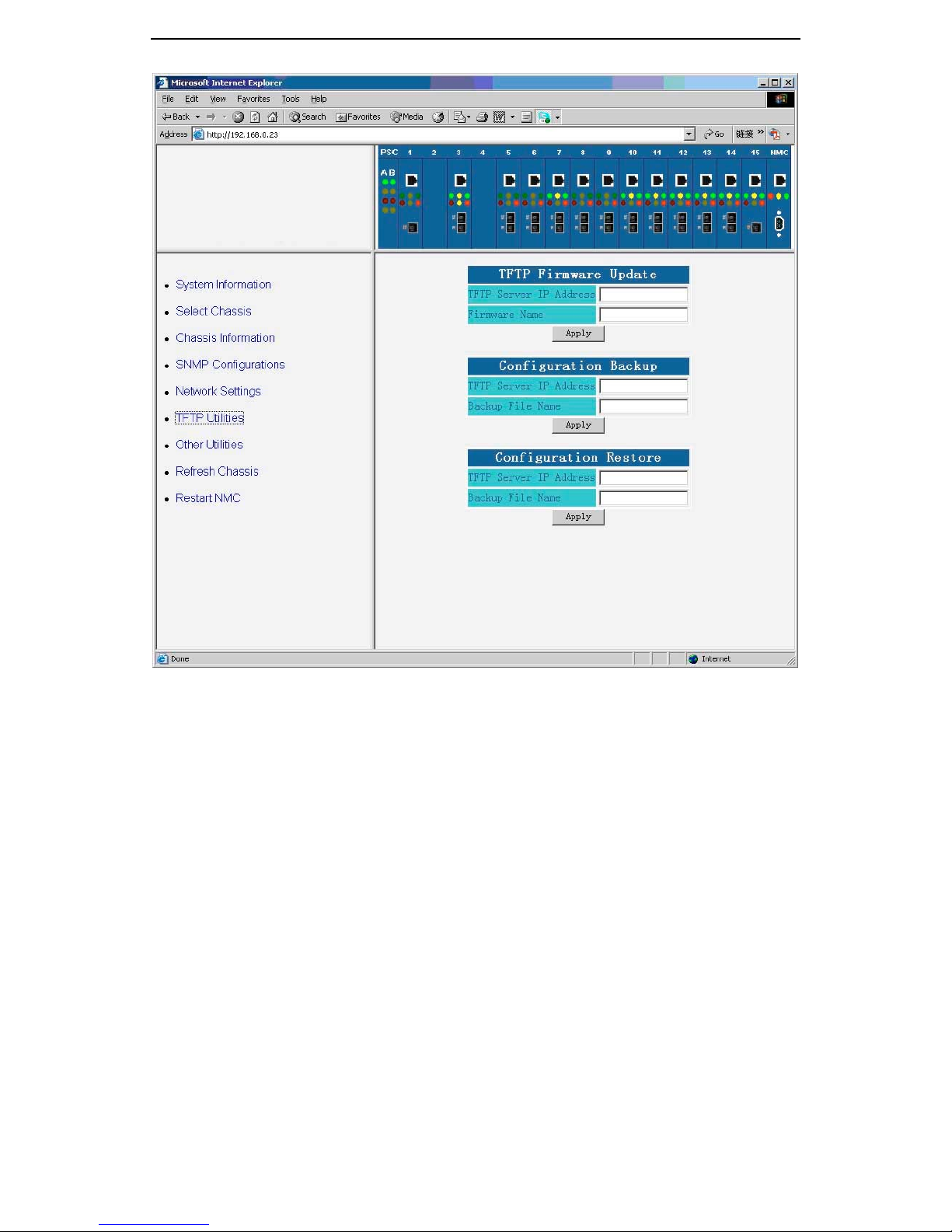
GMC200 media converter system provides TFTP utilities for remotely
updating the system firmware, system configuration backup and restore.
The whole system setup and configuration information can be backup to a
data file and then restore back to the system. This feature is helpful for the
system administrator to keep track the network information in a safe place,
and to speed up the system recover from hardware failure.
The system firmware upgrade utility is only shown when you login as
superuser.
The available TFTP utilities are shown in the following web page capture.
26
Page 33
GMC200 Media Converter System User Guide
3.7 Other Utilities
The other utilities menu includes four items:
• System alarm log,
• Real-Time clock,
• User account settings,
• Serial port settings, and
• Loopback test.
3.7.1 Alarm
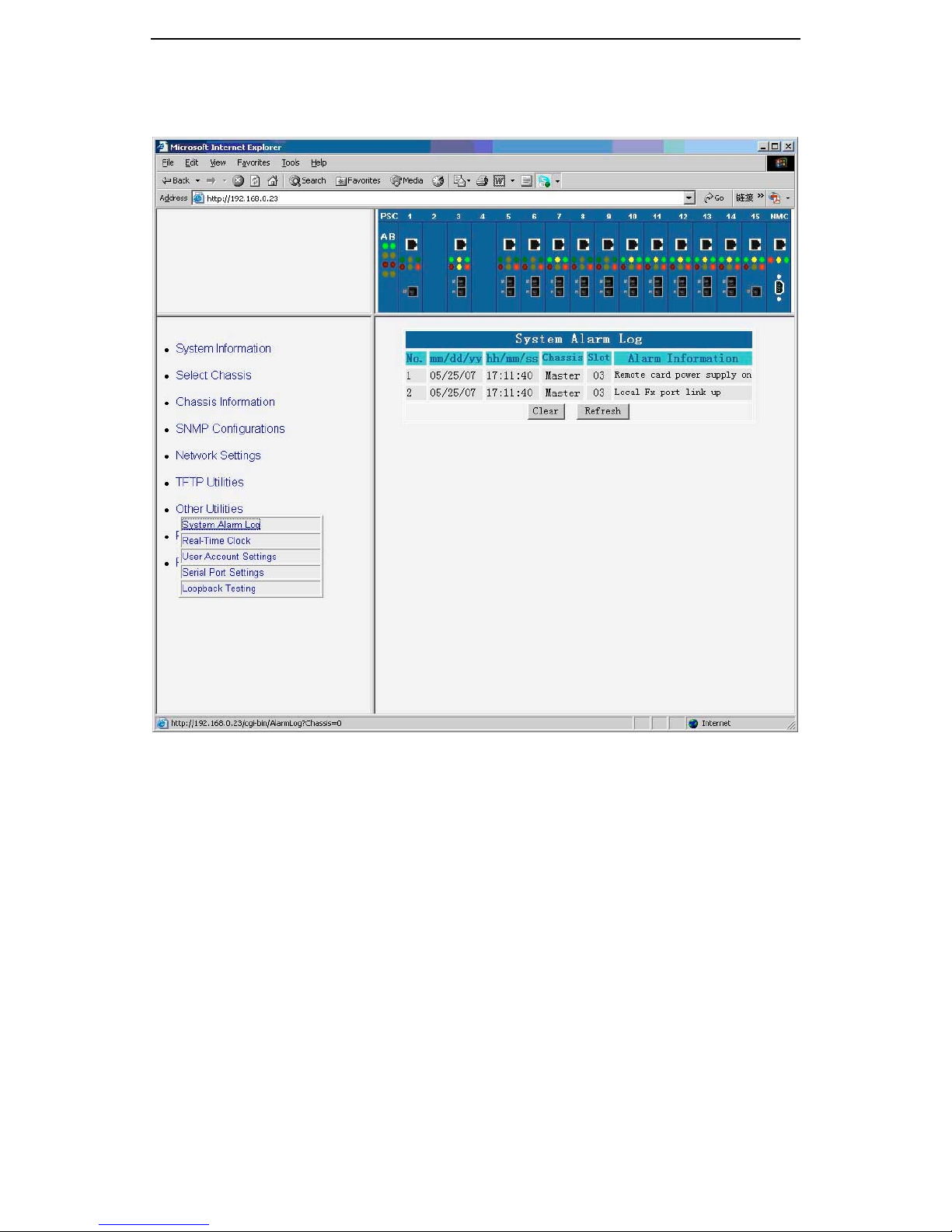
The logged alarms can be shown by clicking “System Alarm Log” under
the “Other Utilities”. The alarms include any change on the local and remote
converters, such as link up and down, power on and off. The logged
information contents the date and time stamps, the location and other related
attributes. You can delete all the logged alarm by clicking “Clear” button on
the page. The sample alarms are captured in the following figure.
It is important to note that the system keeps the most recent 200 alarm
27
Page 34
GMC200 Media Converter System User Guide
records, if you have not cleaned up the alarm log for a long period of time, the
previous alarms will be over-written by the new one.
3.7.2 Real-Time Clock
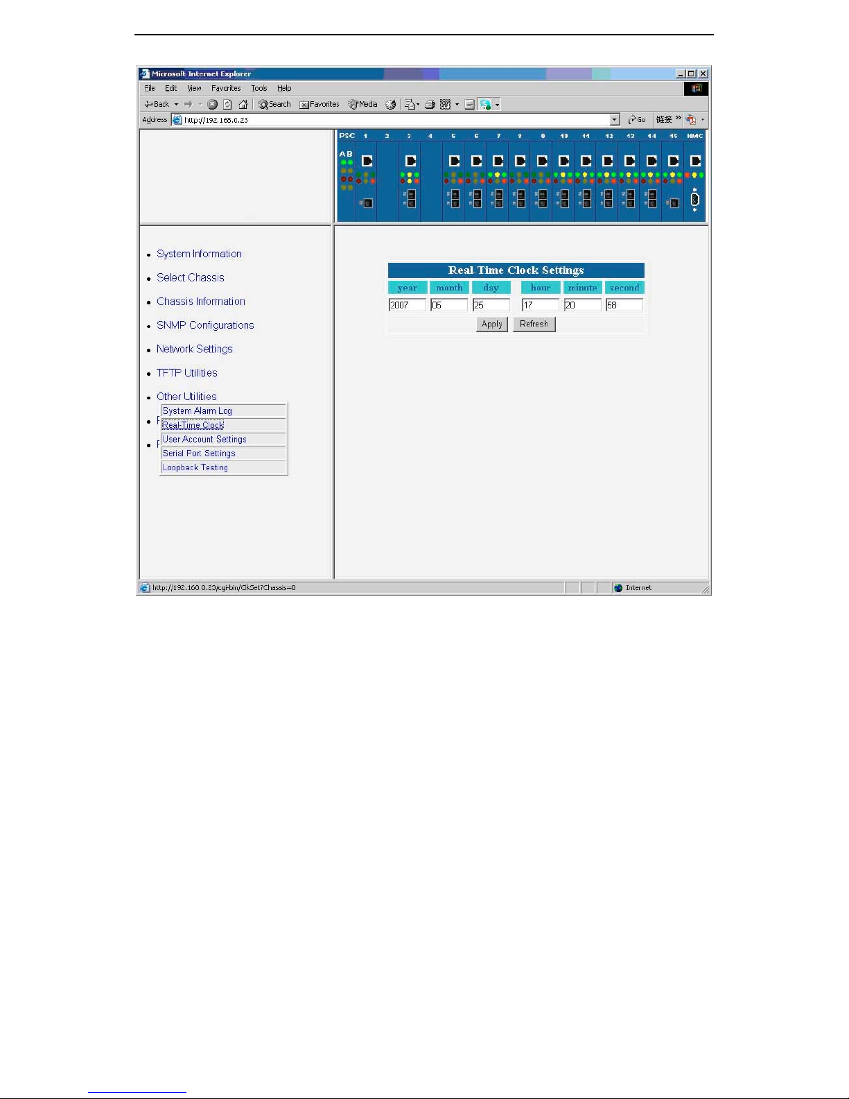
You can show and modify the real-time clock setting by clicking the “RealTime Clock” under the “Other Utilities”. During the alarm logging procedure,
the date and time reading from the real-time clock will be used to help trace
up the alarm events. Please set the date and time correctly.
28
Page 35
GMC200 Media Converter System User Guide
3.7.3 User Account Settings
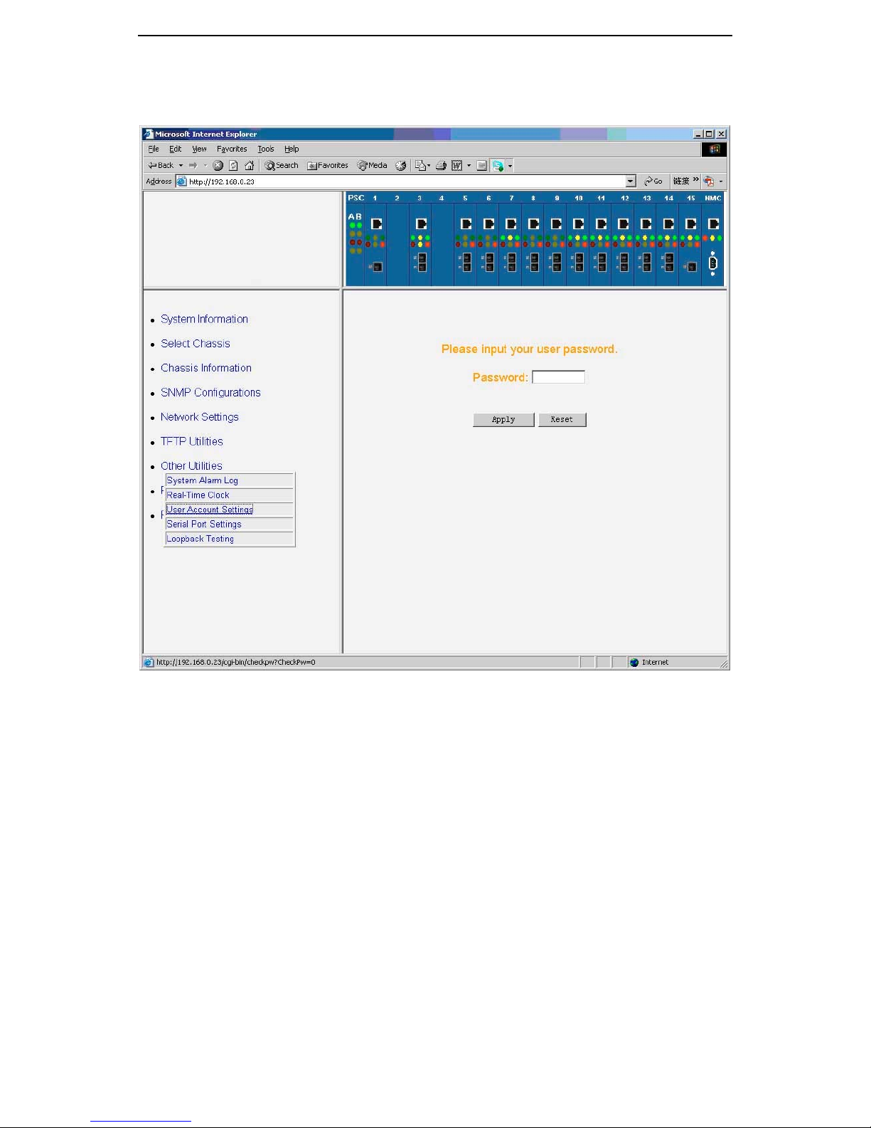
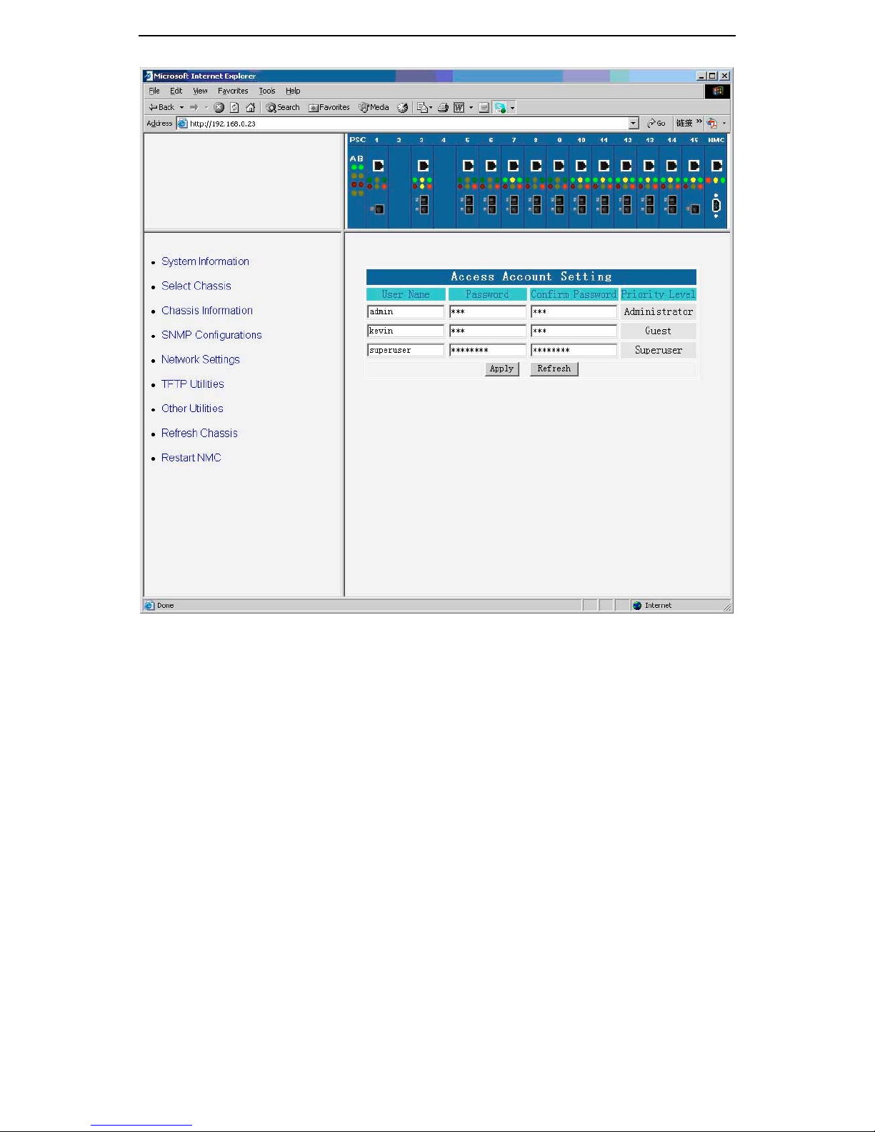
The user account settings page provides you a facility to change the user
names and passwords. The total of user accounts available are three, the
followings are the default settings:
1. “superuser” with default password of “12345678”. This login
account will have all the privilege to change and setup the system
parameters, including the system firmware upgrade.
2. “admin” with default password of “123”. This login account will
have all the privilege to change and setup the system parameters,
except the system firmware upgrade.
3. “guest” with default password of “123” ”. This login account will not
have the privilege to change and setup the system parameters.
It is highly recommended that you should change the password
immediately when the system is in the field and carries the data traffic, and
keep the password in a safe place.
If you somehow forget the password, you can change them back to the
29
Page 36
GMC200 Media Converter System User Guide
factory default by pressing and holding the reset button on the face plat of the
network management card for more than 5 seconds.
30
Page 37
GMC200 Media Converter System User Guide
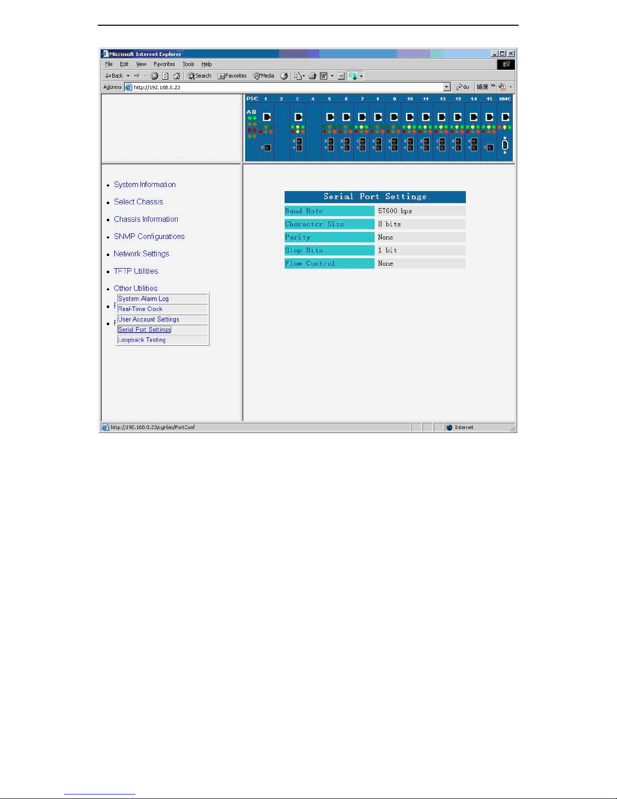
3.7.4 Serial Port Settings
You can show the following serial port setting by clicking the “Serial Port
Settings” under the “Other Utilities”.
31
Page 38
GMC200 Media Converter System User Guide
3.7.5 Loopback Testing
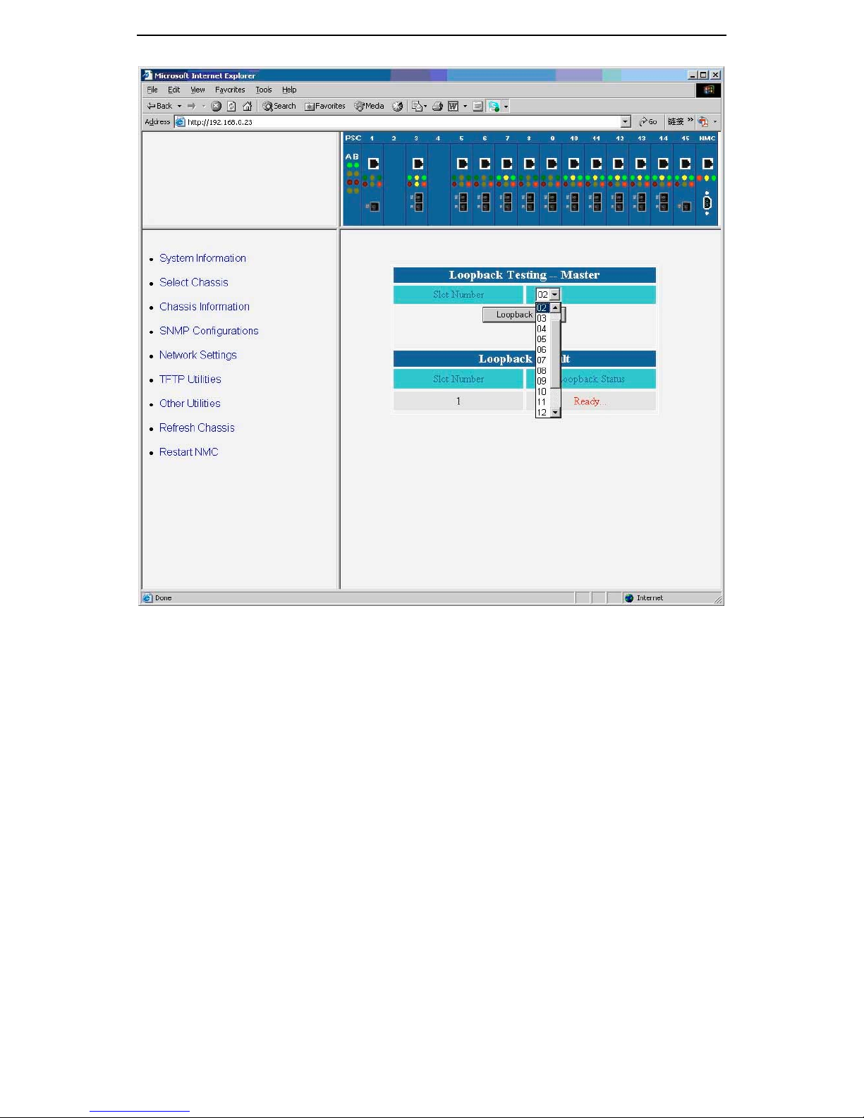
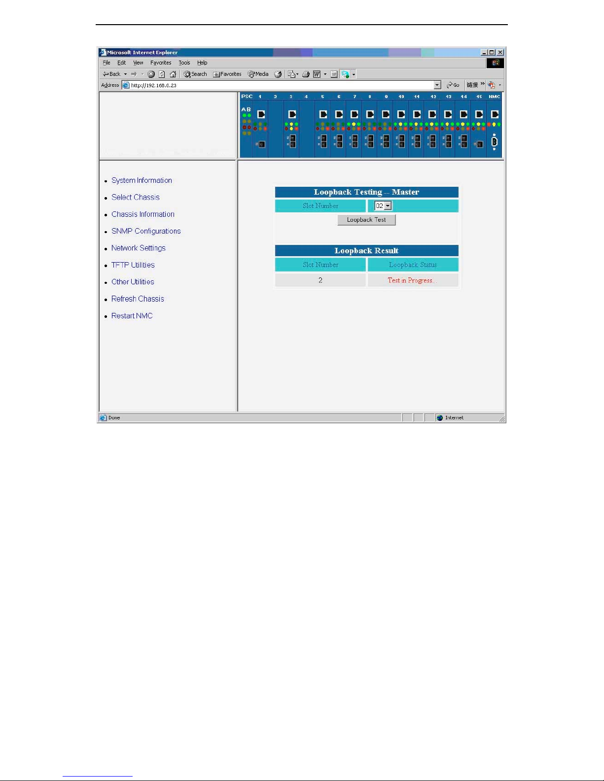
You can show the loopback test page by clicking the “Loopback Testing”
under the “Other Utilities”. If you click the “Apply” button on the “Loopback
Testing” page, the local converter will automatically send out 100 loopback
frames to the remote converter and then check if the loopback frames are
successfully looping back. If there is no CRC error for all the loopback frames
and the frame number is the same as what it is sent, “Pass” will be shown as
the “Loopback Status”. The loopback test will interrupt the normal traffic path,
it will recover the normal traffic path after the loopback has completed.
32
Page 39
GMC200 Media Converter System User Guide
To do the loopback test, you shall follow the two procedures:
• Select the card number to be tested, and click “Loopback Test”
button, you will see the following page:
33
Page 40
GMC200 Media Converter System User Guide
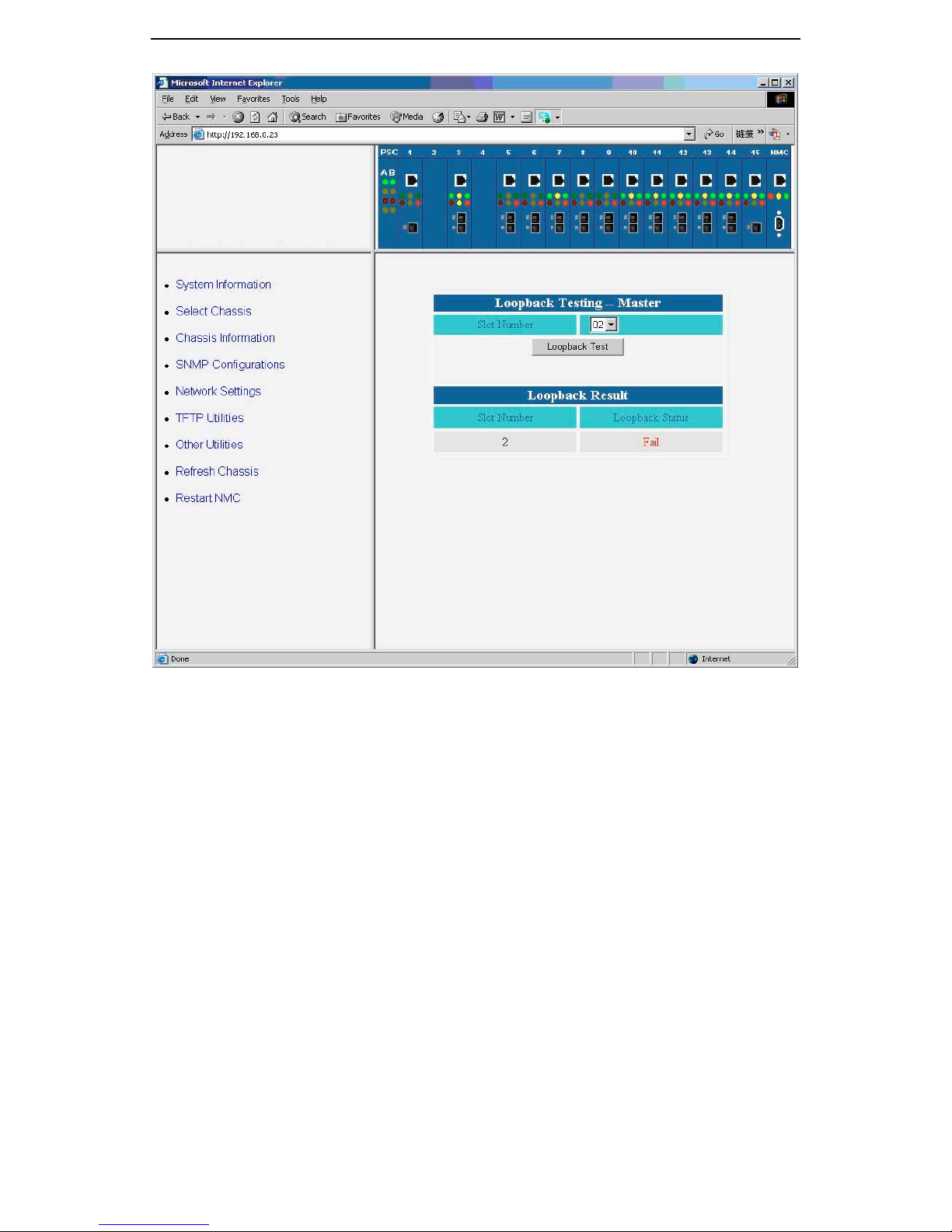
• After a few seconds, the loopback test result will be shown as
following:
34
Page 41
GMC200 Media Converter System User Guide
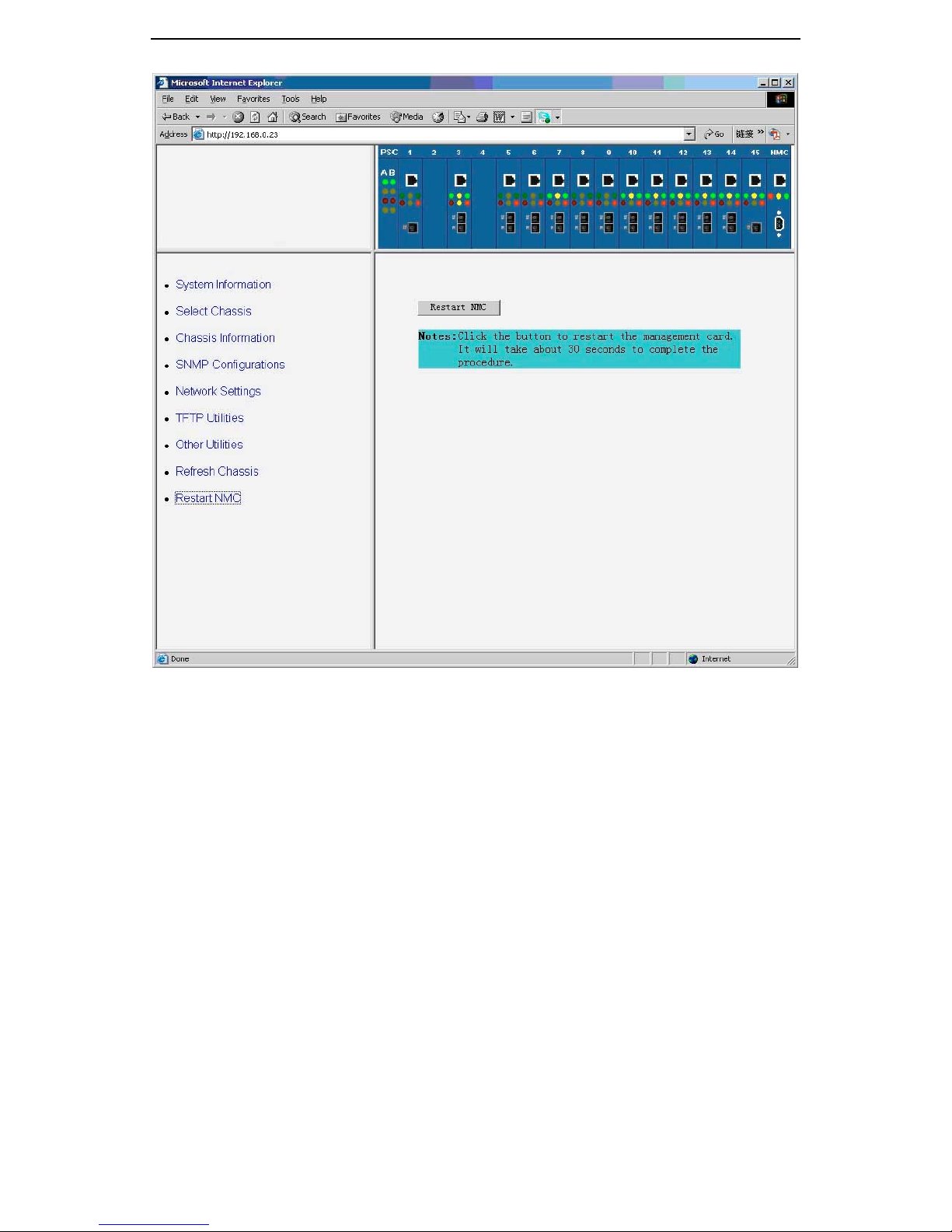
3.8 Restart Chassis
By clicking the “Restart Chassis” button, you can restart the management
module with all the setting unchanged.
35
Page 42
GMC200 Media Converter System User Guide
36
Page 43
GMC200 Media Converter System User Guide
4 SNMP Monitor
GMC200 supports standard Ethernet management protocol, user can
monitor GMC200 through SNMP software. The following examples are taking
‘MIB-Brower’ from iReasoning company to monitor GMC200.
4.1 Software Installation
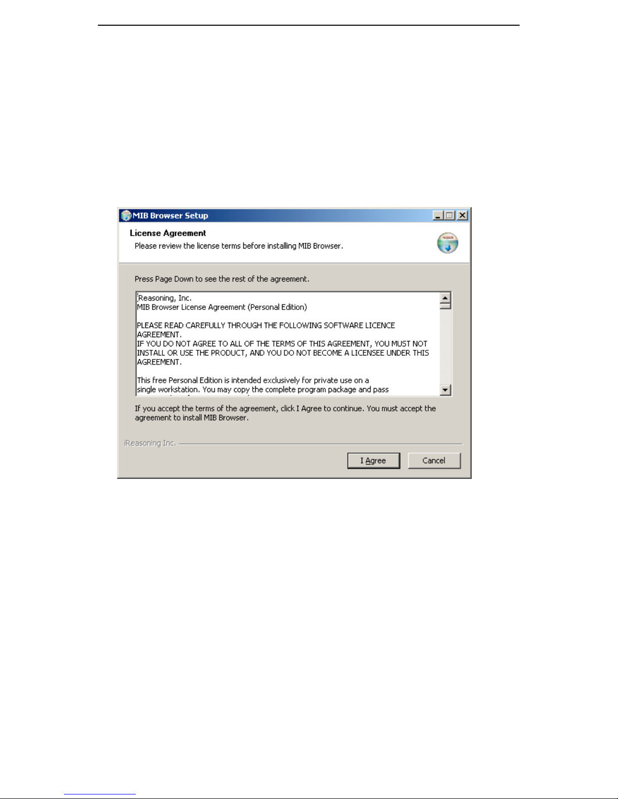
Double click the installation file; it will come on a figure like this,
choose “I agree”
37
Page 44
GMC200 Media Converter System User Guide
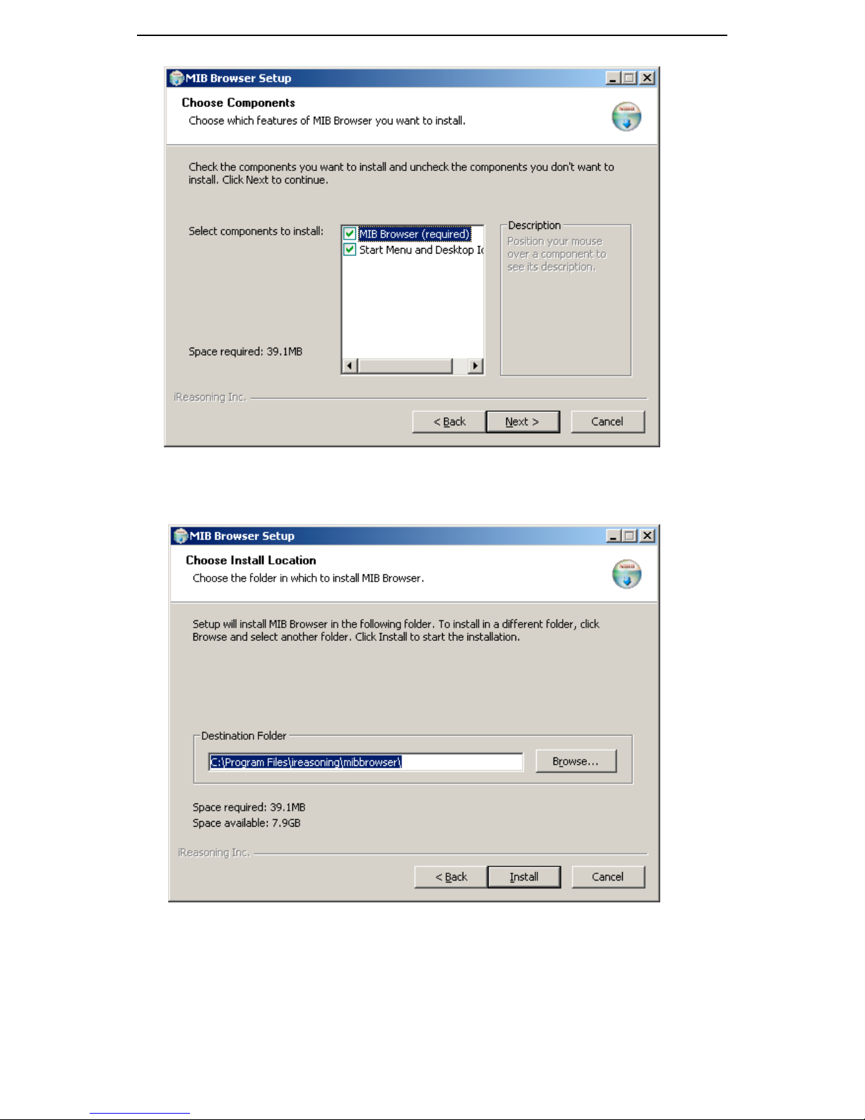
Choose “Next” to select both MIB Brower and Start Menu and Desktop
Icons.
Choose an installation location.
38
Page 45
GMC200 Media Converter System User Guide
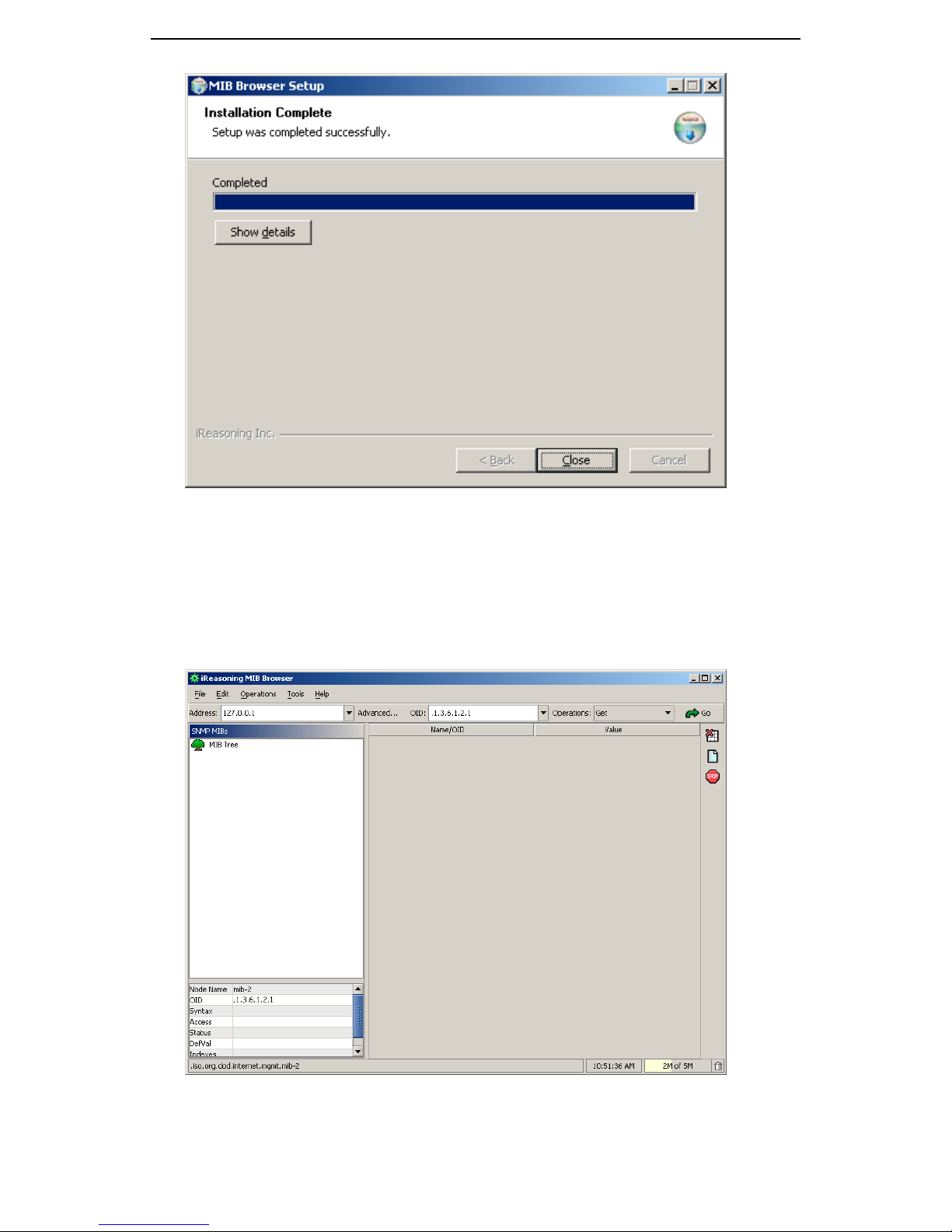
Click “Close” to complete the installation.
4.2 MIB Brower Usages
Launch MIB Brower, the following figure will be shown.
39
Page 46
GMC200 Media Converter System User Guide
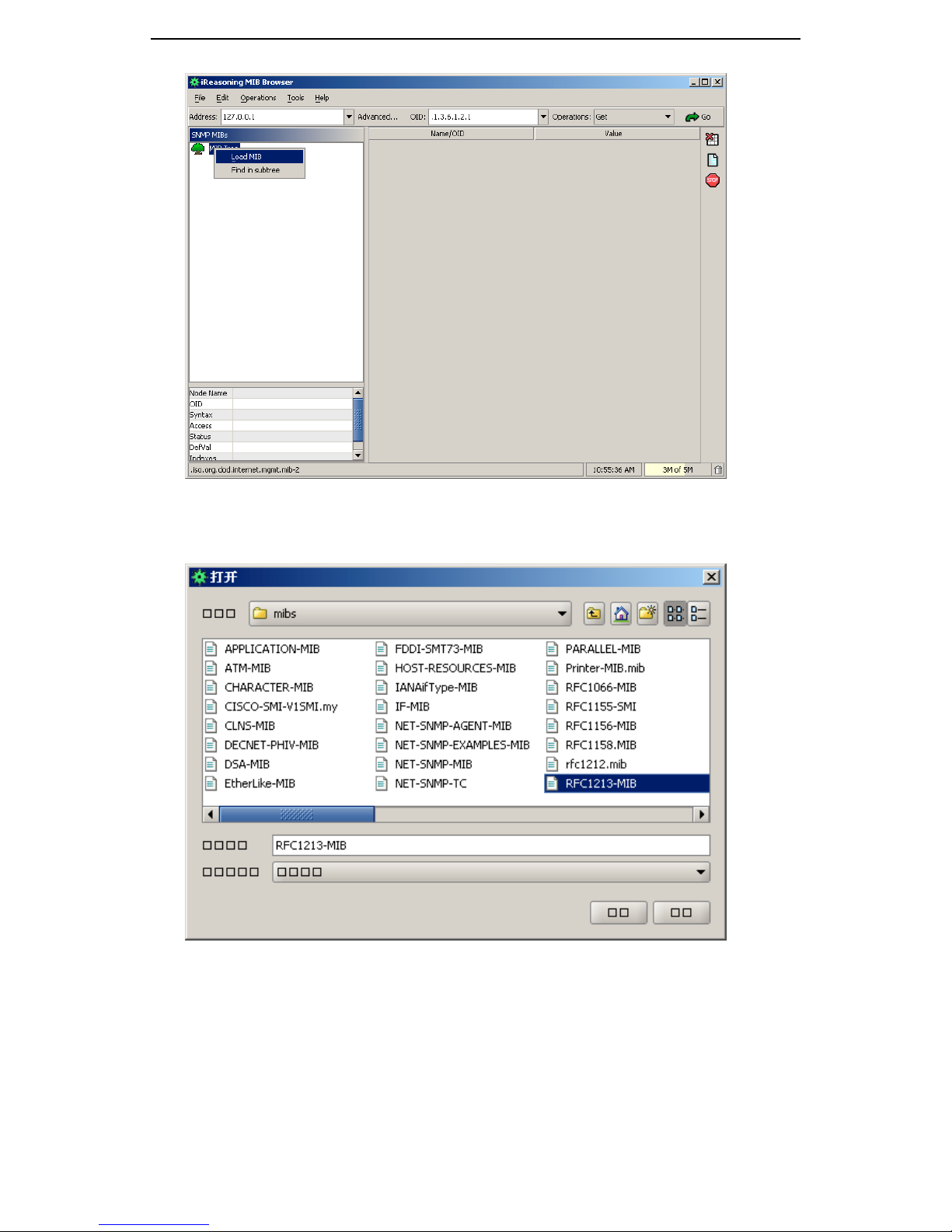
User can load a MIB file to the MIB tree on the top-left.
Choose RFC1213-MIB
The RFC1213-MIB and its associated nodes will be shown like this.
40
Page 47
GMC200 Media Converter System User Guide
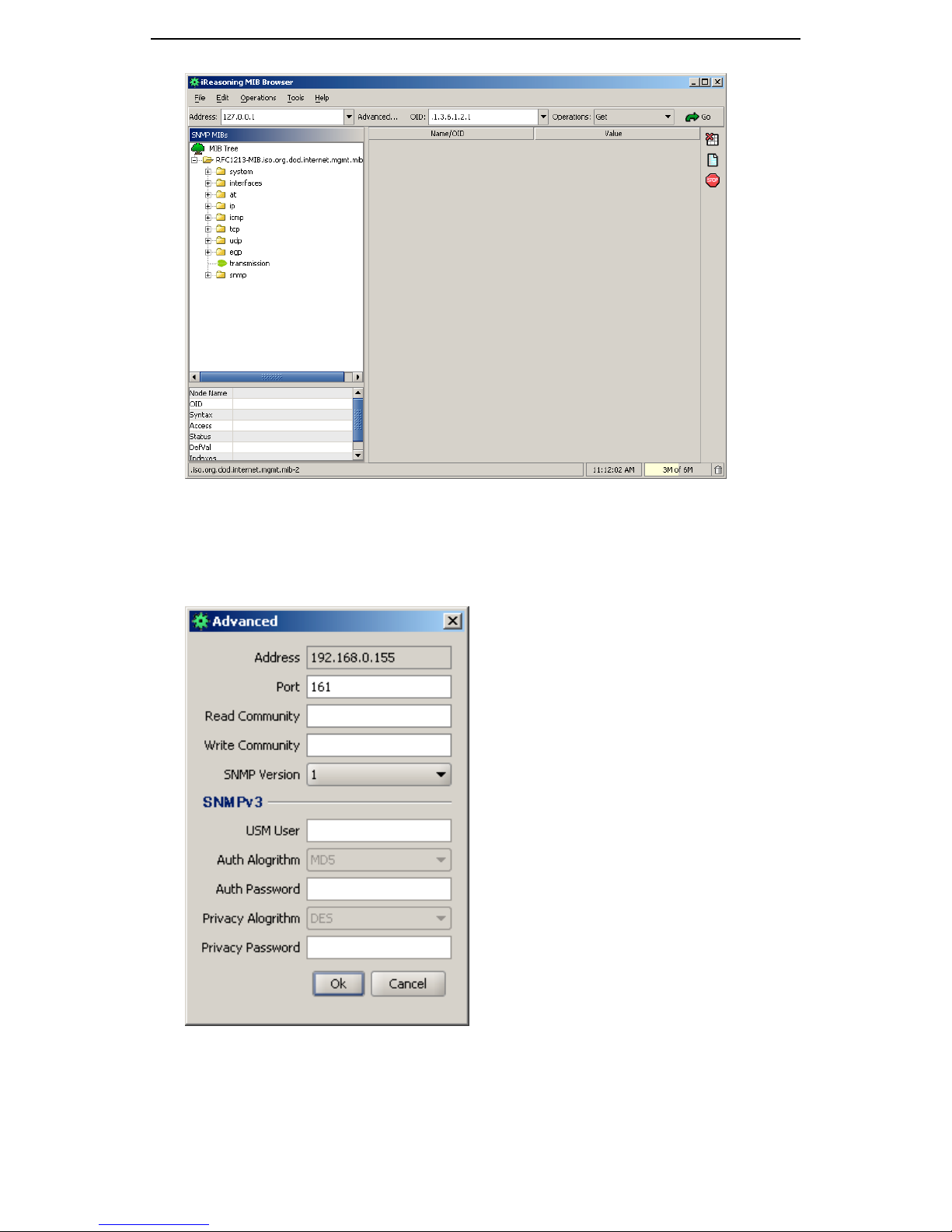
To monitor the GMC200, it required to Input the correct IP address to the
Address column, and click the “advanced…” button, set up the correct read
and write community.
41
Page 48
GMC200 Media Converter System User Guide
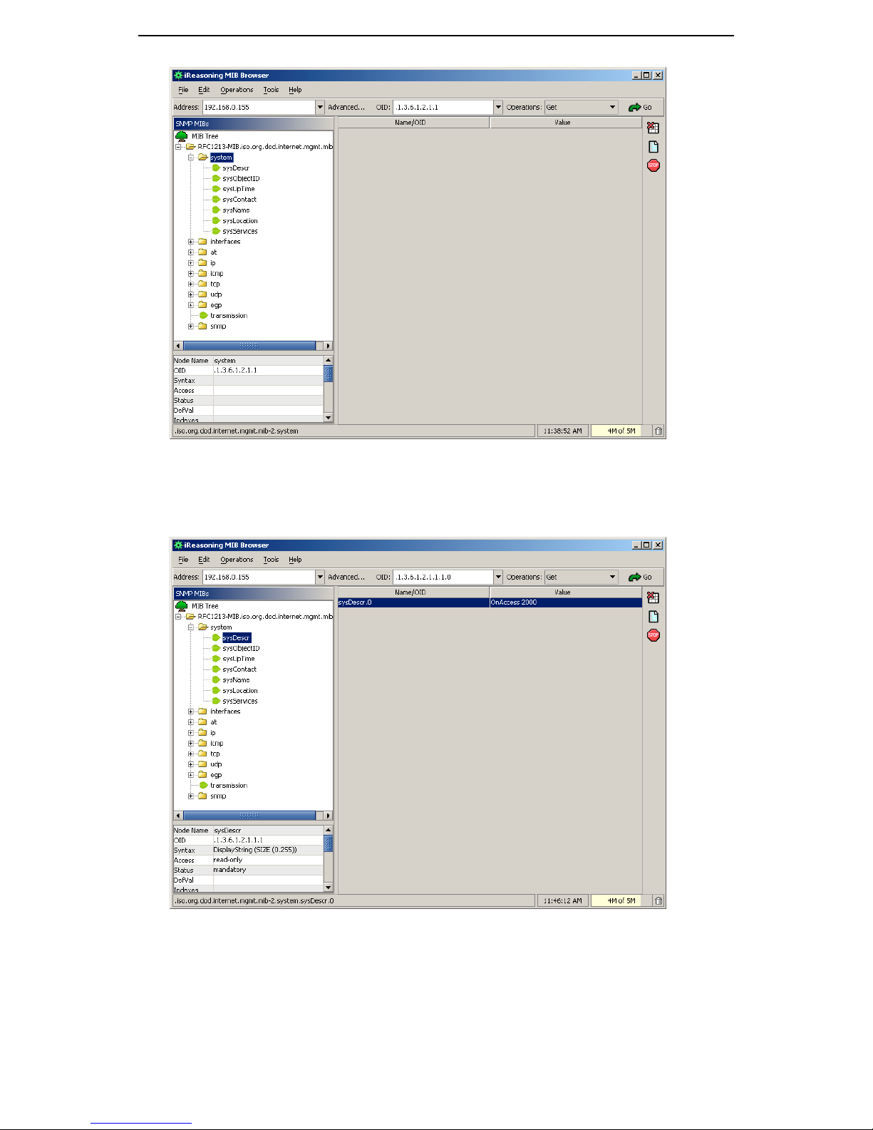
Select “system”, all system node information are listed. Choose
“sysDescr” node and choose “Get” Operation; when the “Go” button has been
clicked, the system description of GMC200 will be given as follow.
However, if the “walk” operation has been chosen at this point, all node
information will be listed on the MIB Brower.
42
Page 49

GMC200 Media Converter System User Guide
5 Command Line Interface (CLI)
GMC200 management software also provides a command line interface
(CLI) to manage and monitor the system. You can follow the console setting
information listed below and use the Windows HyperTerminal or other type of
serial terminal emulation program to perform the system management. You
can also invoke the CLI using telnet utility from any computer, which has
Ethernet connection to the network management card.
COM Properties
• Bits per second = 57600
• Data bits = 8
• Parity bit = None
• Stop bits = 1
• Flow control - None
ASCII Setup
• Append line feeds to incoming line ends
• Wrap lines that exceed terminal width.
5.1 Main Command Menu
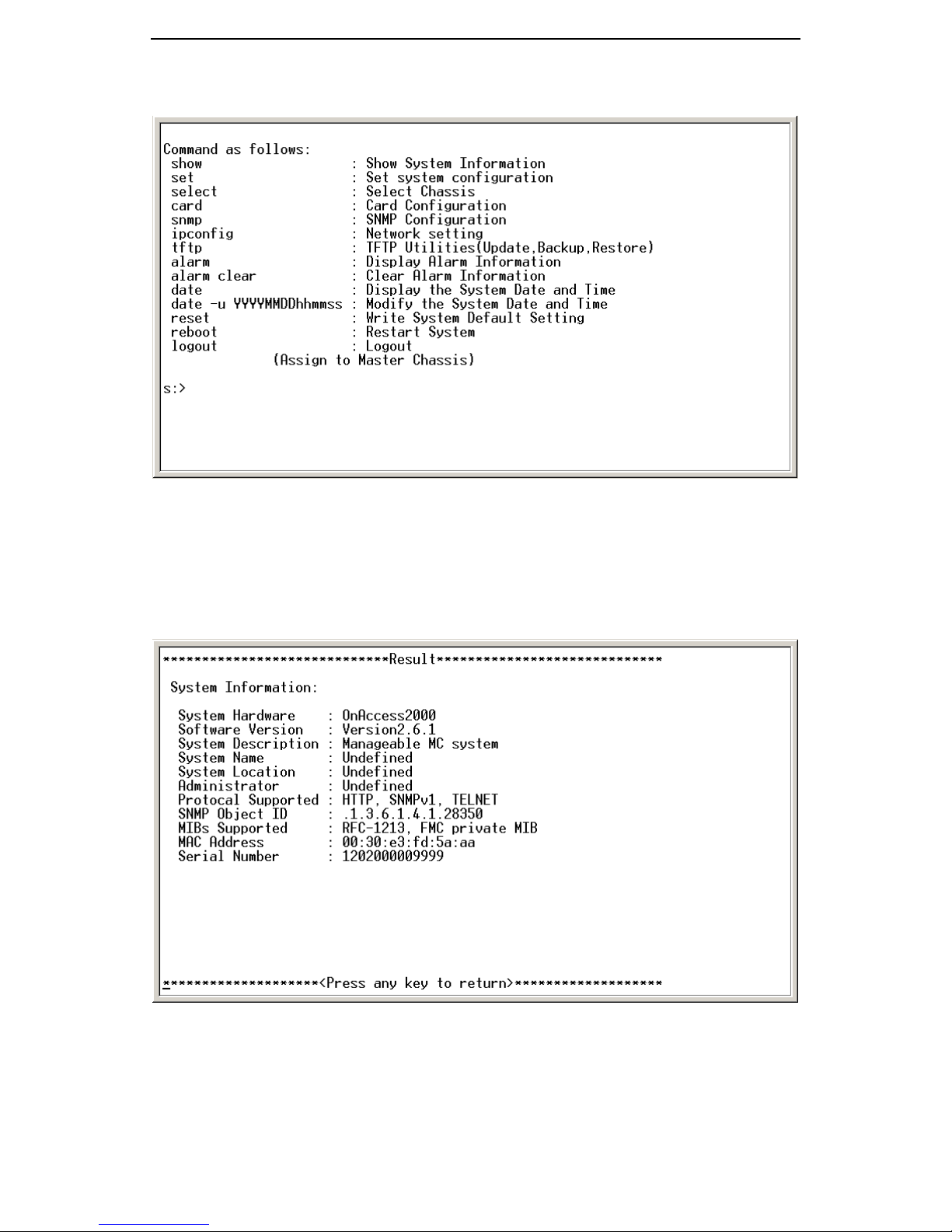
Having setup the terminal at the PC side and connected the terminal to
GMC200 network management card via straight through DB9 cable, you can
start the network management by typing “menu” at the terminal side , then
you will be asked to type the user name and password, as shown below, in
order to login to the management windows.
With the correct user name and password from one of the three login
accounts, the command line management window as shown in the following
43
Page 50
GMC200 Media Converter System User Guide
figure will be activated.
5.2 System Information
The system information will be shown after you type “show” command in
the command line as below. Some of the listed information here can be
modified by “set” command described in later section.
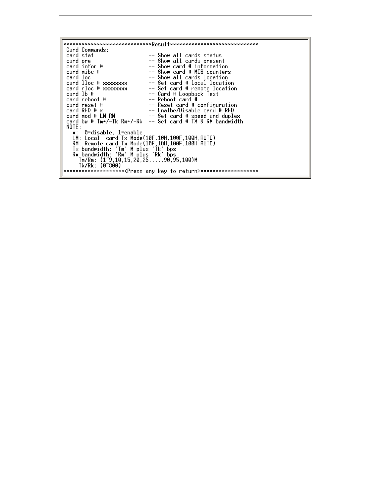
5.3 Card Commands
Card commands are associated with showing the port status and
configuring the local and remote converters. By typing “card” on the command
line, all the card commands will be listed as show in the following figure.
44
Page 51
GMC200 Media Converter System User Guide
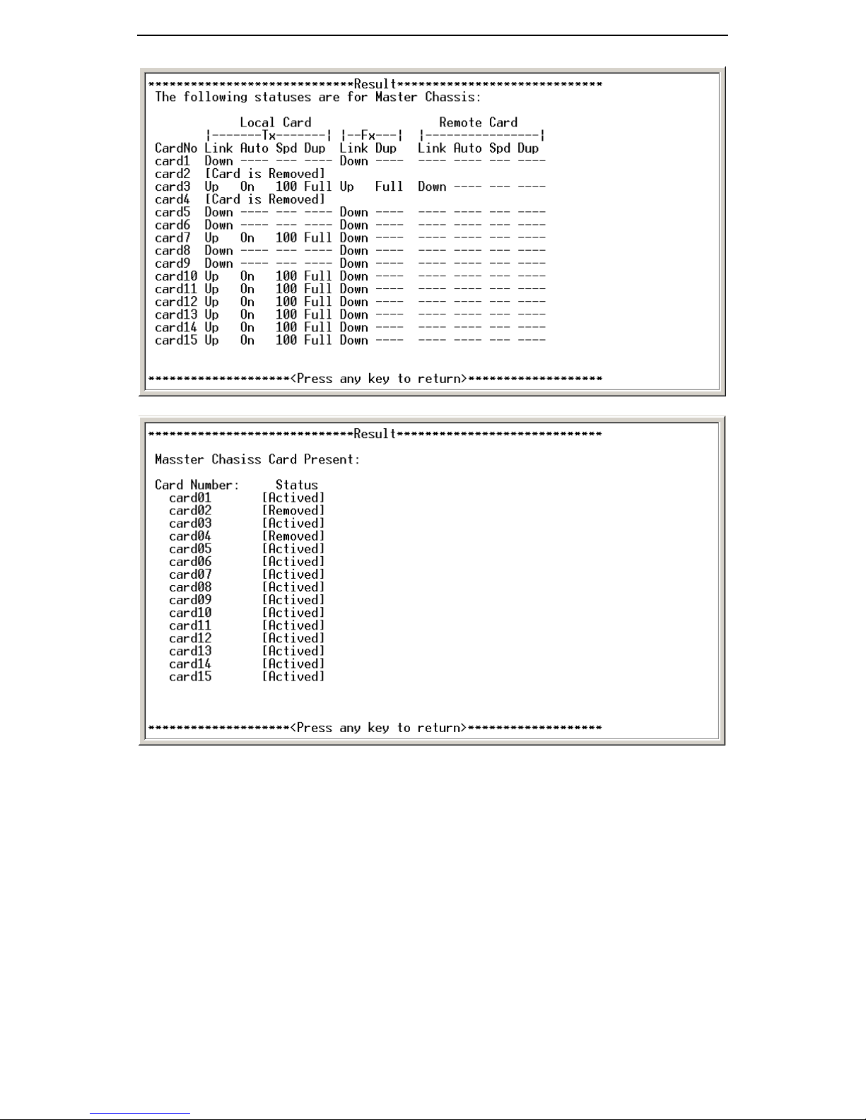
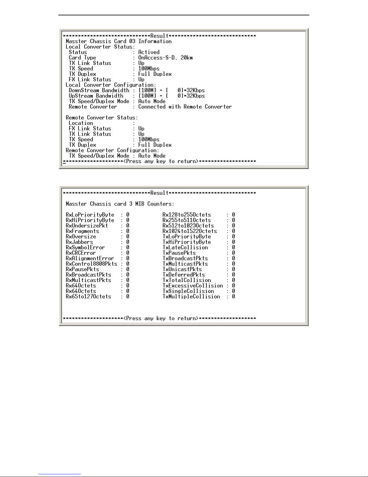
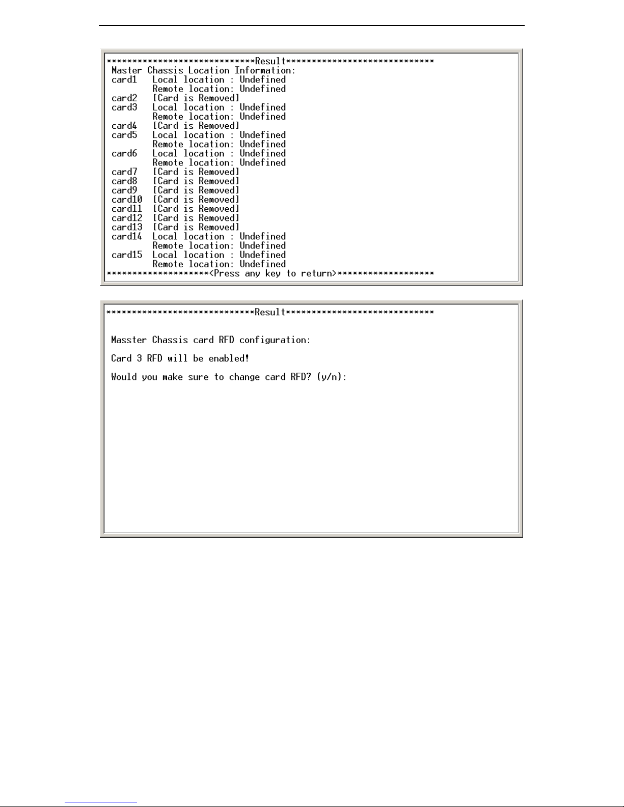
“card stat”, “card pre”, “card infor” and “card loc” commands are used to
display the card status, card present, card information and card location
information, respectively, as shown in the following figures. While the rest of
the commands are used to configure the system. It is important to note “#” in
the above command represents card number or slot number, where 1 ~ 15
will correspond to the converter in the slot. Number “0” is a global selection for
the slots, i.e. if number “0” is used in these commands, it means that slots 1 ~
15 will be selected at the same time.
The converter’s downstream and upstream rates are controlled by the
“card bw” command. The command requires three parameters, the first
parameter refers to the slot number where the converter resides in, and the
second and third one are the downstream and upstream rate setting,
respectively, for example “1+200” means the rate setting of “1M + 200 *128K”.
45
Page 52
GMC200 Media Converter System User Guide
46
Page 53
GMC200 Media Converter System User Guide
47
Page 54
GMC200 Media Converter System User Guide
48
Page 55

GMC200 Media Converter System User Guide
5.4 Select a Chassis
As single management unit of GMC200 can manage up to four chassis,
you must select a chassis at any time before you try to configure and monitor
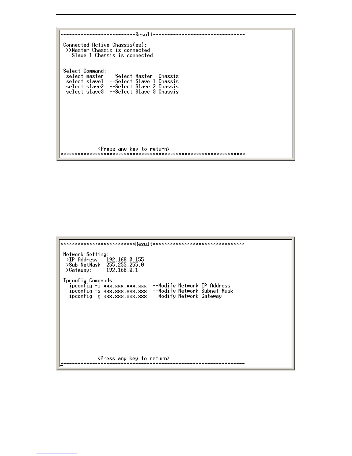
the media converters in the chassis. The four commands used are:
• select master
• select slave1
• select slave2
• select slave3
Where the “master” refers to the chassis with DB9 connecter on the front
panel, which is connected to the management terminal. While the “slave1”,
“slave2” and “slave3” are the chassis connected via the DB9 cable on the rear
panel of the master chassis.
49
Page 56
GMC200 Media Converter System User Guide
5.5 Network Information
The screen capture shown in the following figure is for the network setting
and the related commands. You can follow the command syntax to
reconfigure the network settings, which include the IP address, subnet mask
and gateway. The default settings shown here are the same as listed in the
previous sections in this document.
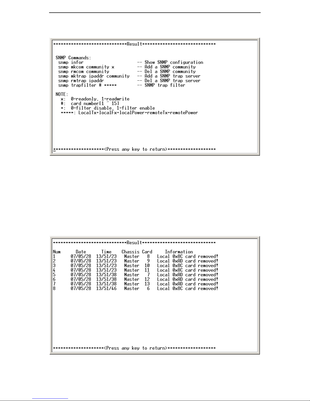
5.6 SNMP
The screen capture shown in the following figure are for SNMP. You shall
configure the parameters properly before you can use SNMP to manage
GMC200 media converter system. Please refer to the SNMP references for
50
Page 57
GMC200 Media Converter System User Guide
you benefits.
5.7 Alarm
Two alarm associated commands are available for the system
administrator. The first one is to list all the alarms logged and the second one
is to clear all the previous alarms.
If you type “alarm’ in the main menu, all the alarm will be shown in the
screen as captured in the following figure. “alarm clear” command will delete
all the logged alarms.
51
Page 58
GMC200 Media Converter System User Guide
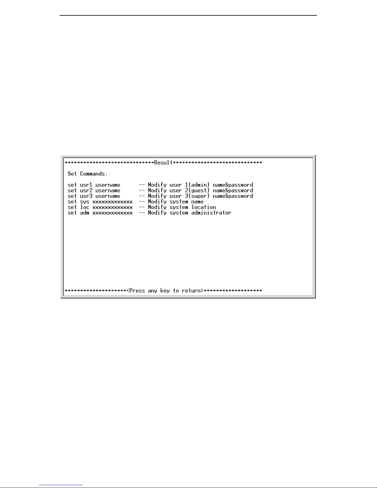
5.8 Set System Information
There are 6 commands used to set the system information, which include
• User account 1 >> include the user name and the password,
• User account 2 >> include the user name and the password,
• System name >> for easy to identify,
• System description >> what is the chassis for,
• System location >> where the chassis and remote converter
located,
• Contact information >> set the administrator’s contact information,
such as telephone number and name.
The command syntax is shown in the following figure.
5.9 Retime System Clock
There are two commands related to the on-board retime system clock.
“date” command is used to display the date and clock information, while the
“date –u” command is to update / modify the system date and clock. The
format for the date / time to be typed is “YYYYMMDDhhmmss”, where
“YYYY” is four digit of the year,
“MM” is two digit of the month,
“DD” is two digit of the day,
“hh” is two digit of the hour,
“mm” is two digit of the minute, and
“ss” is two digit of the second.
52
Page 59

GMC200 Media Converter System User Guide
5.10 Reset Command
After typing “reset’ in the command line, the following interactive page will
appear in the console. You have to confirm the reset action by typing “y”, any
other character will lead to end the “reset” command. The “reset” command is
used to reset the management software and change all the setting back to the
factory default. After “reset” command, you shall reboot the chassis in order to
bring the default setting into effect.
5.11 Reboot Command
After typing “reboot’ in the command line, the following interactive page
will appear in the console. You have to confirm the reboot action by typing “y”,
53
Page 60

GMC200 Media Converter System User Guide
any other character will lead to end the “reboot” command. The “reboot”
command is used to restart the management software and keep all the setting
unchanged.
54
Page 61

Quality Fiber and RF, Inc.
8941 SE Duncan St
Hobe Sound, FL 33455
USA
Tel: (772)545-9757
Cell: (561)427-8931
E-mail: [email protected]
http://www.qfrf.com
 Loading...