

Page 1
WARNING!
WWAA--AAnncchhoorr RRooooff AAnncchhoorr
DO NOT THROW AWAY THESE INSTRUCTIONS!
READ AND UNDERSTAND BEFORE USING EQUIPMENT!
This manual should be read and understood in its entirety, and used as part of a
training program as required by OSHA or any applicable state regulatory agency.
This and any other included instructions must be provided to the users of the
equipment. The user must understand the proper equipment use and limitations.
This product meets all applicable OSHA and ANSI standards for fall protection.
GGuuaarrddiiaann FFaallll PPrrootteeccttiioonn KKeenntt,, WWAA
880000--446666--66338855 wwwwww..gguuaarrddiiaannffaallll..ccoom
m
GGEENNEERRAALL SSYYSSTTEEMM SSEELLEECCTTIIOONN CCRRIITTEERRIIAA::
fall protection equipment shall be made by a Competent Perso n. All fall
protection equipment shall be purchased new and unused.
The equipment is designed for use as a part of a personal fall protection system.
Components shall not be used for any other operation other than that whi c h it has
been desig ned and approved.
Fall Arrest Systems shall be designed to comply with OSHA or applicable state
regulatory limitations. Systems must be used in a compliant manner.
Fall Restraint systems shall be designed by a Qua l ified Person, and must be
installed and used under the supervision of a competent person.
Consult a doctor if there is any reason to doubt a user’s ability to withstand and
safely absorb fall arrest forces. Age, fitness, and health conditions can seriously
affect the worker should a fall occur. Pregnant women and minors should not
use this equipment.
DDOO NNOOTT::
Do not alter or misuse this equipment.
Do not use combinations of components or subsystems
that may affect or interfere with the safe, compatible
function of each other.
Do not expose the equipment to chemicals which may
produce a harmful effect or degrade the equipment.
Consult manufacturer in cases where doubt exists.
Do not use the equipment around moving machinery or
electrical hazards unless specifically designed for such
use.
Do not use the equipment around sharp edges or
abrasive surfaces unless intended for such use.
Selection of
The employer shall provide a training program for each employee who might be exposed to fall hazards. The
TTRRAAIINNIINNGG RREEQQUUIIRREEMMEENNTTSS:
:
program shall enable each empl oyee to recognize the hazards of falling and sh all train each employee in the procedures to be followed in order to
minimize these hazards. Relevant Federal, State, and local regulatory requirements, procedures, and standards shall also be a part of training.
The employer shall ensure that each employee has been trained, as necessary, by a Competent or Qualified Person in the nature of fall hazards in the
work area. Training shall also include the correct erecting, maintaining, disassembling, and inspection of the fall protection systems being used, and
the use of personal fall arres t systems.
The user is required to have a rescue plan and the means at hand to implement it when using the equipment. The plan shall be
RREESSCCUUEE PPLLAANN:
:
project specific. Employees shall be trained in sel f-rescue or alternate means shall be provided for prompt rescue in the event of a fall.
:
IIFF EEQQUUIIPPMMEENNTT IISS SSUUBBJJEECCTTEEDD TTOO AA FFAALLLL:
Remove the equipment fro m ser vi ce immediately if it h as been subjected to the forces of a
fall arrest. Contact your distributor or Guardian about policies regarding replacement of Guardian components involved in a fall.
IINNSSPPEECCTTIIOONN::
Only the manufacturer of this equipment or persons or entities authorized in writing by the manufacturer shall make repairs to fall
protection equipment.
The date of first inspection should be recorded by the employer on the equipment, and any serial numbers shall be recorded on the
Inspection Log.
Formal inspections shall be made by either a Competen t or Qualified Person on at least a semi-annual basis.
PPRRIIOORR TTOO EEAACCHH UUSSEE::
Fall protection equipment shall be inspected by the user for defects, damage, or deteriorat io n.
Any suspected defective eq uipment shall be removed from service.
If the manufacturer’s label is not legible or is missing, the equipment shall be removed from service. Fall protection equipment shall
be removed from service upon evidence of defects, damage, or deterioration, or upon expiration of the manufacturer’s specified
service limits, whichever comes first.
Page 2
WARNING!
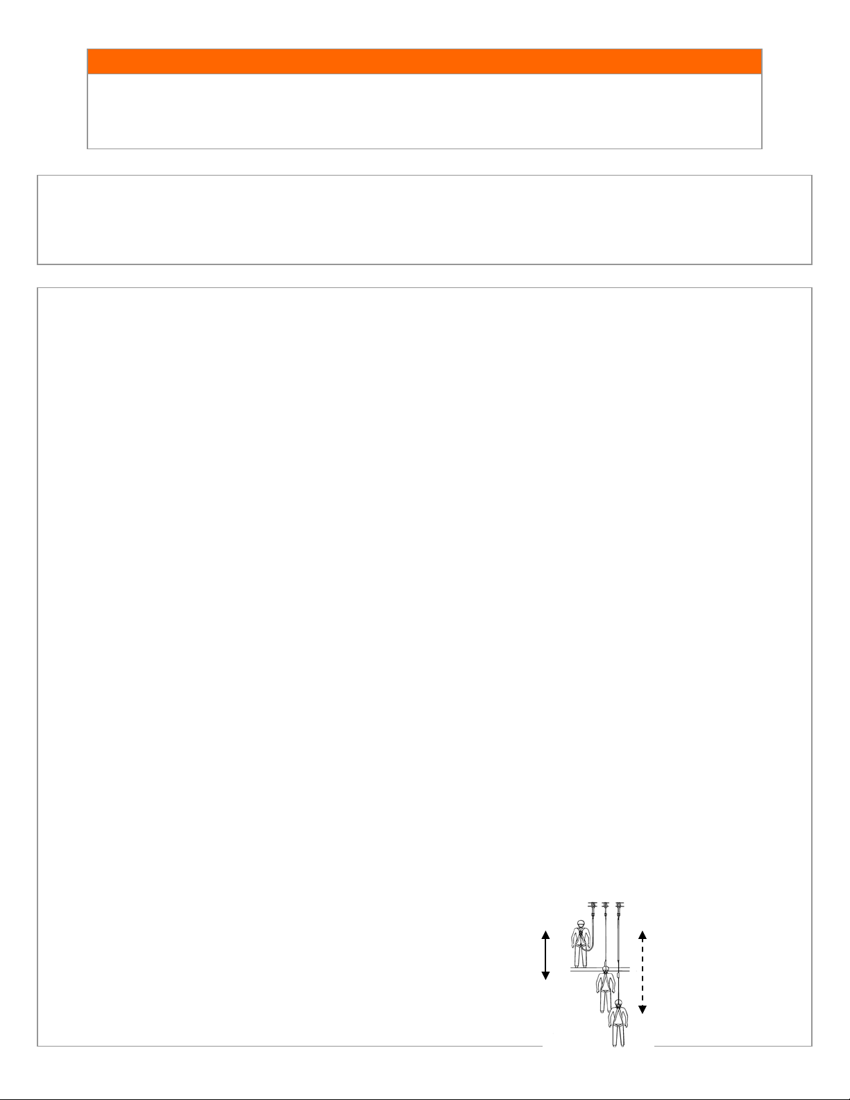
Total Fall Dist ance
6 Feet Max
CCoonnssuulltt wwiitthh yyoouurr ddooccttoorr iiff tthheerree iiss rreeaassoonn ttoo ddoouubbtt yyoouurr ffiittnneessss ttoo ssaaffeellyy aabbssoorrbb tthhee sshhoocckk ffrroomm aa ffaallll aarrrreesstt.. AAggee,,
a
ffiittnneessss,, aanndd hheeaalltthh ccoonnddiittiioonnss ccaann sseerriioouussllyy aaffffeecctt aa wwoorrkkeerr’’ss aabbiilliittyy ttoo wwiitthhsstta
mmuusstt nnoott uussee aannyy GGuuaarrddiiaann FFaallll PPrrootteeccttiioonn eeqquuiippmmeenntt..
nndd ffaallllss.. PPrreeggnnaanntt wwoommeenn aanndd mmiinnoorrss
Repairs to equipment can be made only by a Guardian representative or person or entity
MMAAIINNTTEENNAANNCCEE,, CCLLEEAANNIINNGG,, AANNDD SSTTOORRAAGGEE:
authorized by Guardian. Contact Guardian for maintenance and repair. Cleaning after use is important for maintaining the safety and life of the
equipment. Cleanse the equipment of all dirt, corrosives, and contaminants. If the equipment cannot simply be wiped clean use a mild soap and
water. Rinse, wipe, and hang to dry. Store equipment where i t cannot be affected b y heat, light, excessive mois ture, oil, chemicals, or other
degrading elements.
:
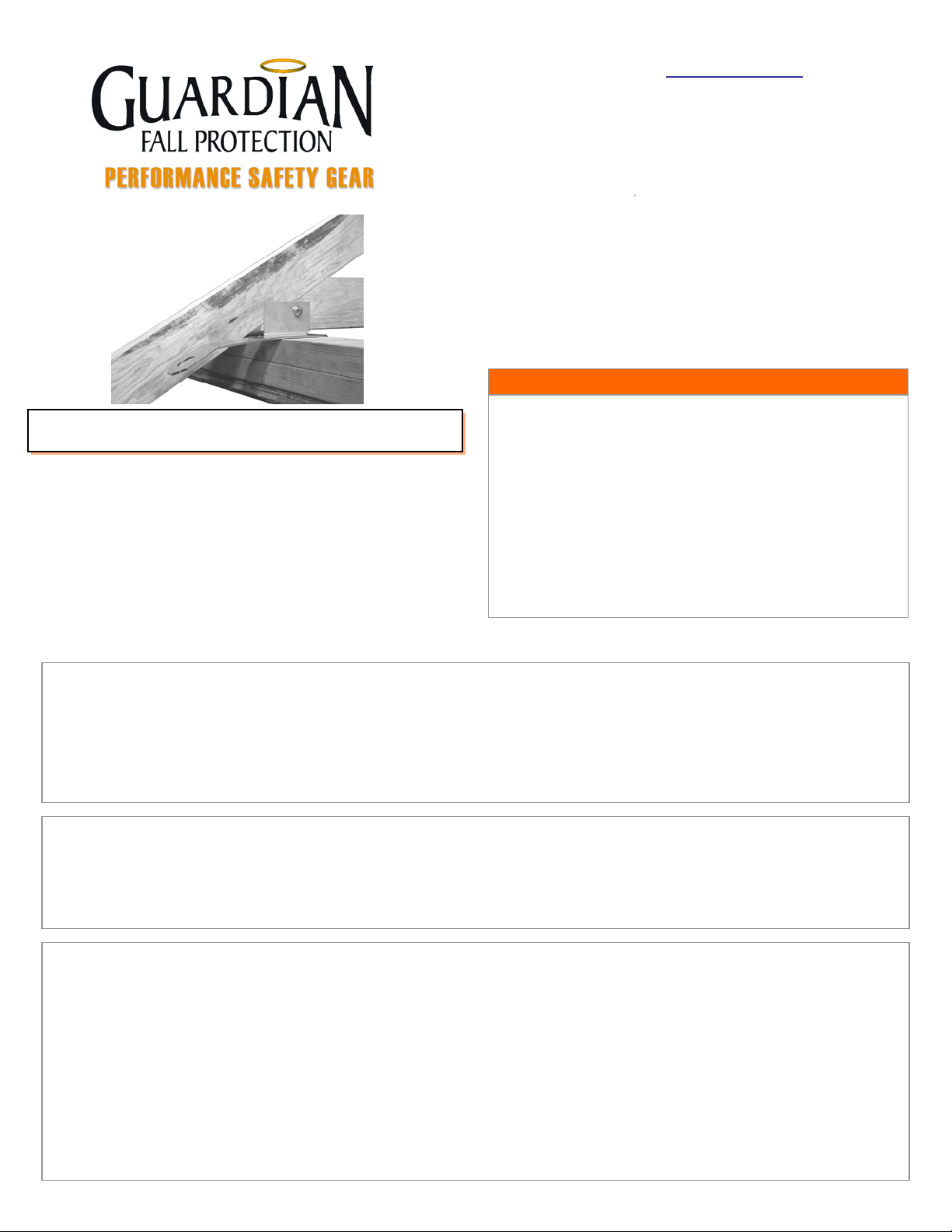
DESCRIPTION OF PRODUCT:
WA-Anchor Roof Ancho r s pro vide a permanent fall protection anchor. When used with provid ed nails and bolt system, WA-Anchor Roof Anchors can be used under
the roof eave to provide fall protection for lower levels. Attach to anchorages meetin g 5,000lbs. load requirem ents or use a sysetm that limits arrest forces to include a
2:1 safety factor.
PRODUCT APPLICATION INFORMATION:
The WA-Anchor Roof Anchor is designed to be used as an anchorage conn ector for personal fall a r rest or restraint for 7/12 roof pitches or less. The struc ture that this
product is attached to must be capable of supporting a 5,000lb. static load in the direction of pull or shall be designed, installed and used as follows: (i) as part of a
complete personal fall arrest system which maintains a minimum safety factor of two; and (ii) under the supervision of a qualified person” per OSHA 1926.502.
Designed specifically for attachment on standard wood framing structural members and approved wall top designs in conjunction with approved truss locations at the
wall.
Do not hang, lift or support tools or equipment from the WA-Anchor Roof Anchor. The use of a shock absorbing connector is
required for fall arrest applications.
PERSONAL FALL ARREST: Means the product is used as a component of a personal fall arrest system to protect the user
in the event of a fall. For this applica tion, the PFAS MUST include a full body harness and a connecting component (energy
absorbing lanyard). Maximum permissible free fall is six feet.
RESTRAINT: Means the product is used as a component of a restraint system to prevent the user from reaching a fall
hazard. Restraint systems typically include a full body harness and a lanyard or restraint line. NO VERTICAL FREE
FALL IS PERMITTED
WORK POSITIONING: Means the product is used as a component of a work positioning system to support the user at a
work position. Work positioning systems typically include a full body harness, positioning lanyard, and a back-up personal
fall arrest system. Maximum pe rmissible free fall is two feet.
RESCUE: This product IS NOT RATED for use as a component of a rescue system.
LIMITATIONS:
Consider the following applica tion limitations before using this equipment.
Capacity: The anchorage connectors are designed for use by persons with a combined weight (clothing, tools, etc.) of no
more than 310lbs. No more than one personal protective system may be connected at one time.
Free Fall: Personal fall arrest systems (PFAS) used with this equipment must be rigged to limit the free fall to six feet as
called out in ANSI Z359.1. Only qualified and trained personnel, on the proper use of fall protection such as this anchor, are
allowed to use this product. Restraint systems must be rigged in a manner such t hat no ver tical free fall is possib le . Work
positioning systems must be rigged in a manner that limits free fall to two feet or less. Rescue systems must be rigged so that
no vertical free fall is possible.
Fall Clearance: A hazard assessment by a trained and competent person is recommended before any work is started that
would include the use of fall protection. There must be sufficient clearance below the user to arrest a fall before the user
strikes the ground or other obstruction. The clearance required is dependent on some or all of the following factors.
Consider When Calculat ing Distance:
Deceleration Distance
Movement of harness attachment element (D-ring)
Free Fall Distance
Worker He ight (how tal l the worker is could affect the
Free Fal l
(Free Fall + Deceleratio n
Distance)
free fall distance)
Elevation of Anchorage Connector
Connecting Subsyste ms Length
Page 3

WARNING!
WARNING!
ATTACH TO OVERHEAD
APPLICABLE STANDARDS:
Refer to pot ential applicable standards. Standards might include OSHA regulations depending on the type of work, and also mig h t i nclude state regulations. Consult
regulator y a g encies for more information on person al fall arrest systems and as sociated components. This product is designed to comply with OSHA and ANSI
standards when used properly, and in accordance with manufacturer’s instructions.
LIMITATIONS CONTINUED:
Swing Falls: Swing falls occur when the anchorage point is not
directly above the point where a fall occurs. The force of striking
an object in a swing fall may cause serious injury or death.
Minimize the risk of swing falls by working as close to the
anchorage point as possible. Do not permit a swing fall if
injury could occur. Swing falls will s ignificantly
increase the clearance required whe n a self retracting
lifeline or other variable length connecting system is
used.
Potential Environmental Hazards: Use of fall protection
equipmen t in areas with environmental hazard s m ay require
additional precautions to prevent injury to the user or d amage to
the equipment. Hazards may include but are not limited to:
chemicals, corrosive en vironments, high voltage power lines ,
gases, moving machinery, and sharp edges.
ANCHORS!
SWING FALLS INCREASE
FALL ARREST DISTANCE.
SYSTEM REQUIREMENTS:
Compatibility of Components: Guardian Fall Protection equipment is designed to be used with Guardian approved
components. Please contact Guardian if you have a question regarding compatibility. Making substitution s without approval
from Guardian Fall Protection may lead to injuries and or death by co mpromising the safety and reliability of t he c omplete
system. A Qualified person can make a determination on compatibility of equipment from different manufacturers. If in
doubt, please contact Guardian Fall Protection for clarification.
Compatibility of Connectors: Connectors (D-rings, hooks, carabiners) must be capable of supporting at least 5,000 lbs.
(22kN). Do not use equipment that is not compatible. No n-compatible connectors may unintentionally disengage. Self
locking snap hooks and carabiners are required by ANSI and OSHA. Connectors must be compatible in size, shape, and
strength.
Making Conne cti ons: Only use self-locking snap hooks and carabiners with any Guardian Fall Protection equipment. Do not
use equipment that is not comp a tible. If you have any questions on co mpatibility, please call Guardian Fall Protection at
800.466.6385.
LLaarrggee tthhrrooaatt ooppeenniinngg ssnnaapp hhooookkss sshhoouulldd nnoott bbee ccoonnnneecctteedd ttoo ssttaannddaarrdd ssiizzee DD--rriinnggss oorr ssiimmiillaarr oobbjjeeccttss wwhhiicchh wwiillll rreessuulltt
iinn aa llooaadd oonn tthhee ggaattee iiff tthhee hhooookk oorr DD--rriinngg ttwwiissttss oorr rroottaatteess.. LLaarrggee tthhrrooaatt ssnnaapp
hhooookkss aarree ddeessiiggnneedd ffoorr uussee oonn ffiixxeedd
ssttrruuccttuurraall eelleemmeennttss ssuucchh aass rreebbaarr oorr ccrroossss mmeemmbbeerrss tthhaatt aarree nnoott sshhaappeedd iinn aa wwaayy tthhaatt ccaann ccaappttuurree tthhee ggaattee ooff tthhee hhooookk..
PERSONAL FALL ARREST INFORMATION:
Personal Fall Arrest System (PFAS): Personal fall arrest systems used with this equipment must meet applicable state,
federal, OSHA, and ANSI requirements. A full body harness must be worn when this equipment is used as a component of a
personal fall arrest system. As required by OSHA, the personal fall arrest system must be capable of arresting the user’s fall
with a maximum arresting force o f 1, 800 lbs., and limit the free fall to six feet or less.
If overhead tie off is not feasible, and an approved system has the potential for a free fall greater than six feet,
and up to a maximum of ten feet, Guardian Fall Protection recommends using a personal fall arrest system
incorporating a Guardian Fall Protection Heavy Duty Shock Absorbing Lanyard. The Heavy Duty Lanyard is
designed to keep fall arresting forces below the required standard of 1,800 lbs. Standard type lanyards might
generate impact fall forces in excess of the legal requirement when subjected to a free fall of more than 6ft.
Page 4

WARNING!
WARNING!
ANCHORAGE STRENGTH REQUIREMENT:
The anchorage strength required is dependent on the application. Following are anchorage strength requirements for specific
applications. Ensure that any anchorage p oint used in a personal fall protectio n system meet the following requirements.
Fall Arrest: The structure to which the anchorage connector is attached must sustain static loads applied in the directions
permitted by the fall arrest syste m of at lea st 3,600lbs. with certification of a qualified person, or 5,000lbs. without
certification. Refer to OSHA and ANSI for specific definition. This anchor is to be used by one worker only. Do not tie off
equipment. Anchorages used for attachment of a personal fall arrest system shall be independent of any anchorage being
used to support or suspend platforms.
Restraint: The structure to which the a nchor point is a tta ched must sustain static loads applied in the directions per mitted by
the restraint system of at least 3,000lbs. When more than one restraint system is attached to an anchorage, the strengths
stated above must be multiplied by the number of restraint systems attached to the anchorage.
Work Positioning: The structure to which t he anchor point is attached must s ustain static loads applied in the directions
permitted by the work positioning system of at least 3,000lbs., or twice the potential impact load, whichever is greater. When
more than one work positioning system is attached to an anchorage, the strengths stated above must b e multiplied by the
number of work positioning systems attached to the anchorage.
INSPECTION OF
WA-Anchor ROOF ANCHOR:
IIff iinnssppeeccttiioonn rreevveeaallss aann uunnssaaffee oorr ddeeffeeccttiivvee ccoonnddiittiioonn,, rreemmoovvee tthhee pprroodduucctt ffrroomm sseerrvviiccee aanndd ddeessttrrooyy iitt iimmmmeeddiiaatteellyy..
Before each use of this equipment inspect it acc ording to the following guidelines:
A formal inspection of fall protection products/components must be performed at least every six months by a competent
person other than the user. The frequency of formal inspections should be based on conditions of use or exposure. Record
the inspection results in the inspection and maintenance log at the end of this manual.
Inspecting the WA-Anchor Roof Anchors:
Step 1. Inspect the anchor point for damage or corrosion. Inspect for cracks or wear that may affect strength and operation.
Step 2. Inspect the attaching f a stener s. Fasteners must hold the WA-Anchor Roof Anchor securely to the anchorage. Inspect for
damage or corrosion.
Step 3. Inspect the system components according to the manufacturer’s instructions.
Step 4. Record the inspection r e sults in a formal inspection log.
PLAN THE FALL P ROTECTION S YSTEM:
Before installation plan your system. Consider all factors that will affect your safety during use of this equipment. The following
list gives important points to consider when planning your system:
Anchorage: Select a rigid anchorage capable of supporting the loads no less than 5,000 lbs. per worker attached or shall be
designed, installed and used as follows: (i) as part of a complete personal fall arrest system which maintains a minimum
safety factor of two; and (ii) under the supervision of a qualified person” as per OSHA 1926.502.
Sharp Edges: Avoid working where system components may be in contact with, or abrade against, unprotected sharp edges.
After a Fall: Components which have been subjected to the forces of arresting a fall must be removed from service and
destroyed.
Rescue: The employer must have a rescue plan when using this equipment. The employer must have the ability to perform a
rescue quickly and safely.
Page 5

WARNING!
Installed 3.5” 16d nails (qty. 4) and
Installation point and alignment showing
INSTALLATION REQUIREM ENTS:
The following requirements outline the proper installation proc e dures to be followed.
Location: Select a location on an appropriate strength anchorage that will provide overall safety and proper loading. The
anchorage must be free of deformities, weather deterioration, or defects that may weaken the structure. WA-Anchor is for
use on a 7/12 pitch or less.
IIff iinnssppeeccttiioonn rreevveeaallss aann uunnssaaffee oorr ddeeffeeccttiivvee ccoonnddiittiioonn,, rreemmoovvee tthhee WWAA--AAnncchhoorr RRooooff AAnncchhoorr ffrroomm sseerrvviiccee
aanndd ddeessttrrooyy iitt iimmmmeeddiiaatteellyy..
Structure: The structure to which the anchorage connector is attached must be void of any cracks, corrosion, and defects
that may weake n the structure. Do not install anchor to gable ends, facias, rake ends, overhangs, bottom cords, collar boards,
spliced sections, damaged frami ng, or framing that is not structurally capable of withstanding anticipated loads in the
direction of the pull.
Installing the WA-Anchor Roof Anchor:
Step 1. Select a mounting location for the WA-Anchor Roof Anchor that meets or exceeds the strength
requirements. Installation sites must be selected to minimize the swing fall hazard and to limit the free
fall distance to less than 6ft. WA-Anchor fits up to 7/12 pitch.
Step 2. Place the inspected WA-Anchor anchor at the desired approved location and drill the rafter for
installation of the provided WA-Anchor Grade 8 Bolt.
Step 3. Install the provided Grade 8 Bolt and nut through the WA-Anchor and the pre-drilled rafter.
Step 4. Install the 4 provided 3.5” 16d nails through the pre-drilled holes in the back of the WA-
Anchor, securing each nail into the top of the wall.
DO NOT USE WITHOUT THE PROVIDED GRADE 8 BOLT & LOCK NUT!
WA-Anchor positioned on the top of wall
against rafter. For us e on pitches 7/12 or less.
provided Grade 8 bolt and nut.
Page 6

WARNING!
WA-Anchor Roof Anchor
WARNING!
Materials:
WA-Anchor
DO NOT REMOVE LABEL!
Making Connections:
Connecting to the Anchorage Connector:
TRAINING:
It is the responsibility of the user and the purchaser of this equipment to assure they are familiar with these instructions, trained in
the correct care and use of, and are aware of the operating characteristics, application limits, and the consequences of improper
use of this equipment.
SPECIFICATIONS:
FFaaiilluurree ttoo iinnssttaallll aanndd uussee iinn aa ccoommpplliiaanntt mmaannnneerr,, oorr vviioollaattiioonn ooff mmaannuuffaaccttuurreerr’’ss rreeccoommmmeennddaattiioonnss,,
ccaann rreessuulltt iinn sseerriioouuss iinnjjuurryy oorr ddeeaatthh..
When using a hook to co nnect to the WA-Anchor Roof Anchor, ensure roll-out cannot occur.
Roll-out occurs when interference between the hook and mating connector causes the hook gate to unintentionally
open and release.
Self-locking snap hooks and carabiners should be used to reduce the possibility of roll-out. Do not use hooks or
connectors that will not comple te ly close over the attachment object.
Connect to the installed anchorage connector with a self locking snap hook or self locking carabiner only.
Connect only compatible components and equipment to the anchorage connector.
Do not use a knot to connect a lifeline to the anchorage connector.
Do not pass lanyard or lifeline through the anchorage connector and hook back into the lanyard or lifeline itself unless
the lanyard and anchor are approved for such use and a Competent person reviews that the connections are compatible.
Never connect more than one personal protective system to a single anchorage connector.
TTrraaiinniinngg sshhoouulldd bbee ccoonndduucctteedd wwiitthhoouutt eexxppoossiinngg aannyyoonnee ttoo aa ffaallll hhaazzaarrdd..
TTrraaiinniinngg sshhoouulldd bbee rreeppeeaatteedd oonn aa ppeerriiooddiicc bbaassiiss iinn aaccccoorrddaannccee wwiitthh yyoouurr
Stainless Steel
Protection. Kent, WA 253-854-5877
Complies with applicable OSHA/ANSI
standards. 5,000lb. rated anchor. Read
and understand all instructions included
from manufacturer before use!
1 person per anchor. Max. user
weight including tools is 310lbs.
Material: Stainless Steel.
Inspect anchor and installation location
before each installation for cracks,
excessive wear, and deterioration.
Anchorage structures shall be capable of
withstanding 5,000lbs.
Connecting systems should be protected
from sharp or abrasive surfaces. Do not
make incompatible connections. Do not
reuse anchors.
Warning: Avoid physical hazards such as
thermal, electrical, or chemical elements
that could impact the integrity of the
equipment. For use on 712 pitch or less.
Installation: Drill rafter and tighten lock
nut to bolt. Install all provided 16d
fasteners into pre-drilled holes before
use. Do not reuse fasteners. Do not use
without provided Grade 8 bolt & lock nut.
Remove from service if subjected to a
fall arrest or if unit fails inspection.
For fall protection use only.
by Guardian Fall
GGuuaarrddiiaann FFaallll PPrrootteeccttiioonn,, IInncc..
800-466-6385
26513 79th Ave. S.
Kent, WA 98032
www.guardianfall.com
 Loading...