

Page 1
GGuuaarrddiiaann FFaallll PPrrootteeccttiioonn KKeenntt,, WWAA
880000--446666--66338855 wwwwww..gguuaarrddiiaannffaallll..ccoomm
GGEENNEERRAALL SSYYSSTTEEMM SSEELLEECCTTIIOONN CCRRIITTEERRIIAA::
fall protection shall be made by a Competent Person. All fall protection
equipment shall be purchased new and unused.
The equipment is designed for use as a part of a personal fall protection system.
Components shall not be used for any other operation other than that which it has
been designed and approved.
Fall Arrest Systems shall be designed to comply with OSHA or applicable state
Fall Restraint systems shall be designed by a Qualified Person, and must be
installed and used under the supervision of a competent person.
Consult a doctor if there is any reason to doubt a user’s ability to withstand and
safely absorb fall arrest forces. Age, fitness, and health conditions can seriously
affect the worker should a fall occur. Pregnant women and minors should not
use this equipment.
Selection of
GGuuaarrddiiaann HHaarrnneessss IInnssttrruuccttiioonnss
DO NOT THROW AWAY THESE INSTRUCTIONS!
READ AND UNDERSTAND BEFORE USING EQUIPMENT!
This manual should be read and understood in its entirety, and used as part of a
training program as required by OSHA or any applicable state regulatory agency.
This and any other included instructions must be provided to the users of the
equipment. The user must understand the proper equipment use and limitations.
This product meets all applicable OSHA and ANSI standards for fall protection.
DDOO NNOOTT::
• Do not alter or misuse this equipment.
• Do not use combinations of components or subsystems
that may affect or interfere with the safe, compatible
function of each other.
• Do not expose the equipment to chemicals which may
produce a harmful effect or degrade the equipment.
Consult manufacturer in cases where doubt exists.
• Do not use the equipment around moving machinery or
electrical hazards unless specifically designed for such
use.
• Do not use the equipment around sharp edges or
abrasive surfaces unless intended for such use.
WARNING!
:
TTRRAAIINNIINNGG RREEQQUUIIRREEMMEENNTTSS:
program shall enable each employee to recognize the hazards of falling and shall train each employee in the procedures to be followed in order to
minimize these hazards. Relevant Federal, State, and local regulatory requirements, procedures, and standards shall also be a part of training.
The employer shall provide a training program for each employee who might be exposed to fall hazards. The
The employer shall ensure that each employee has been trained, as necessary, by a Competent or Qualified Person in the nature of fall hazards in the
work area, the correct erecting, maintaining, disassembling, and inspection of the fall protection systems being used, and the use of personal fall
arrest systems.
The user is required to have a rescue plan and the means at hand to implement it when using the equipment. The plan shall be
RREESSCCUUEE PPLLAANN:
project specific. Employees shall be trained in self-rescue or alternate means shall be provided for prompt rescue in the event of a fall.
:
:
IIFF EEQQUUIIPPMMEENNTT IISS SSUUBBJJEECCTTEEDD TTOO AA FFAALLLL:
fall arrest. Contact your distributor or Guardian about policies regarding replacement of Guardian components involved in a fall.
Remove the equipment from service immediately if it has been subjected to the forces of a
IINNSSPPEECCTTIIOONN::
• Only the manufacturer of this equipment or persons or entities authorized in writing by the manufacturer shall make repairs to fall
protection equipment.
• The date of first inspection should be recorded by the employer on the equipment, and any serial numbers shall be recorded on the
Inspection Log.
• Formal inspections shall be made by either a Competent or Qualified Person on at least a semi-annual basis.
PPRRIIOORR TTOO EEAACCHH UUSSEE::
• Fall protection equipment shall be inspected by the user for defects, damage, or deterioration.
• Any suspected defective equipment shall be removed from service.
• If the manufacturer’s label is not legible or is missing, the equipment shall be removed from service. Fall protection equipment shall
be removed from service upon evidence of defects, damage, or deterioration, or upon expiration of the manufacturer’s specified
service limits, whichever comes first.
Page 2
(
CCoonnssuulltt wwiitthh yyoouurr ddooccttoorr iiff tthheerree iiss rreeaassoonn ttoo ddoouubbtt yyoouurr ffiittnneessss ttoo ssaaffeellyy aabbssoorrbb tthhee sshhoocckk ffrroomm aa ffaallll aarrrreesstt.. AAggee,,
ffiittnneessss,, aanndd hheeaalltthh ccoonnddiittiioonnss ccaann sseerriioouussllyy aaffffeecctt aa wwoorrkkeerr’’ss aabbiilliittyy ttoo wwiitthhssttaanndd ffaallllss.. PPrreeggnnaanntt wwoommeenn oorr mmiinnoorrss
mmuusstt nnoott uussee aannyy GGuuaarrddiiaann FFaallll PPrrootteeccttiioonn eeqquuiippmmeenntt..
WARNING!
:
MMAAIINNTTEENNAANNCCEE,, CCLLEEAANNIINNGG,, AANNDD SSTTOORRAAGGEE:
authorized by Guardian. Contact Guardian for maintenance and repair. Cleaning after use is important for maintaining the safety and life of the
equipment. Cleanse the equipment of all dirt, corrosives, and contaminants. If the equipment cannot simply be wiped clean use a mild soap and
water. Rinse, wipe, and hang to dry. Store equipment where it cannot be affected by heat, light, excessive moisture, oil, chemicals, or other
degrading elements.
Repairs to equipment can be made only by a Guardian representative or person or entity
DESCRIPTION OF PRODUCT:
Guardian Harnesses are designed and tested to comply with applicable OSHA and ANSI standards for fall protection equipment. When used as a component in a
personal fall arrest system, or a personal restraint system, the Guardian harnesses provide workers with the full body harness system designed to allow the body to help
absorb the impacts of a fall should one occur.
PRODUCT APPLICATION INFORMATION:
The Guardian harnesses are designed to be used as body wear for personal fall arrest, restraint, work positioning, or suspension systems. Do not use the fall protection
harness for any purpose that is not related to occupational safety and fall protection systems.
• PERSONAL FALL ARREST: Means the product is used as a component of a personal fall arrest system to protect the user
in the event of a fall. PFAS typically include a full body harness and a connecting component (energy absorbing lanyard).
Maximum permissible free fall is six feet.
• RESTRAINT: Means the product is used as a component of a restraint system to prevent the user from reaching a fall
hazard. Restraint systems typically include a full body harness and a lanyard or restraint line. NO VERTICAL FREE
FALL IS PERMITTED
• WORK POSITIONING: Means the product is used as a component of a work positioning system to support the user at a
work position. Work positioning systems typically include a full body harness, positioning lanyard, and a back-up personal
fall arrest system. Maximum permissible free fall is two feet.
• RESCUE: This product can be used as a full body harness component of a rescue system. See the specific fall protection
plan for harness design qualifications.
• EXTENDED SUSPENSION: A full body harness is not designed for extended suspension applications unless some form
of specifically designed seat is used. A seat board, boatswain’s chair, or seat sling is recommended.
LIMITATIONS:
Consider the following application limitations before using this equipment.
• Capacity: The anchorage connectors are designed for use by persons with a combined weight (clothing, tools, etc.) of no
more than 310lbs. No more than one personal protective system may be connected at one time.
• Free Fall: Personal fall arrest systems (PFAS) used with this equipment must be rigged to limit the free fall to six feet as
called out in ANSI Z359.1. Only qualified and trained personnel, on the proper use of fall protection such as this anchor, are
allowed to use this product. Restraint systems must be rigged that no vertical free fall is possible. Work positioning systems
must be rigged so that free fall is limited to two feet or less. Rescue systems must be rigged so that no vertical free fall is
possible.
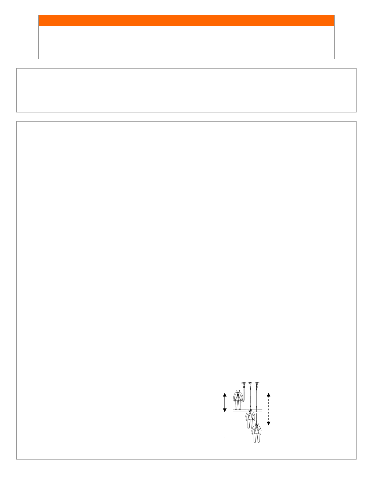
• Fall Clearance: There must be sufficient clearance below the user to arrest a fall before the user strikes the ground or other
obstruction. The clearance required is dependent on some or all of the following factors. A hazard assessment by a trained
and competent person is recommended before any work is started that would include the use of fall protection.
Consider When Calculating Distance:
• Deceleration Distance
• Movement of harness attachment
element (D-ring)
• Free Fall Distance
6 Feet Max
Free Fall
Total Fall Distance
Free Fall + Deceleration
• Worker Height (how tall the worker is
could affect the free fall distance)
• Elevation of Anchorage Connector
• Connecting Subsystems Length
Page 3
APPLICABLE STANDARDS:
Refer to potential applicable standards. Standards might include OSHA regulations depending on the type of work, and also might include state regulations if
applicable. Consult regulatory agencies for more information on personal fall arrest systems and associated components. This product is designed to comply with
OSHA and ANSIZ359.1 standards when used properly, and in accordance with manufacturer’s instructions.
LIMITATIONS CONTINUED:
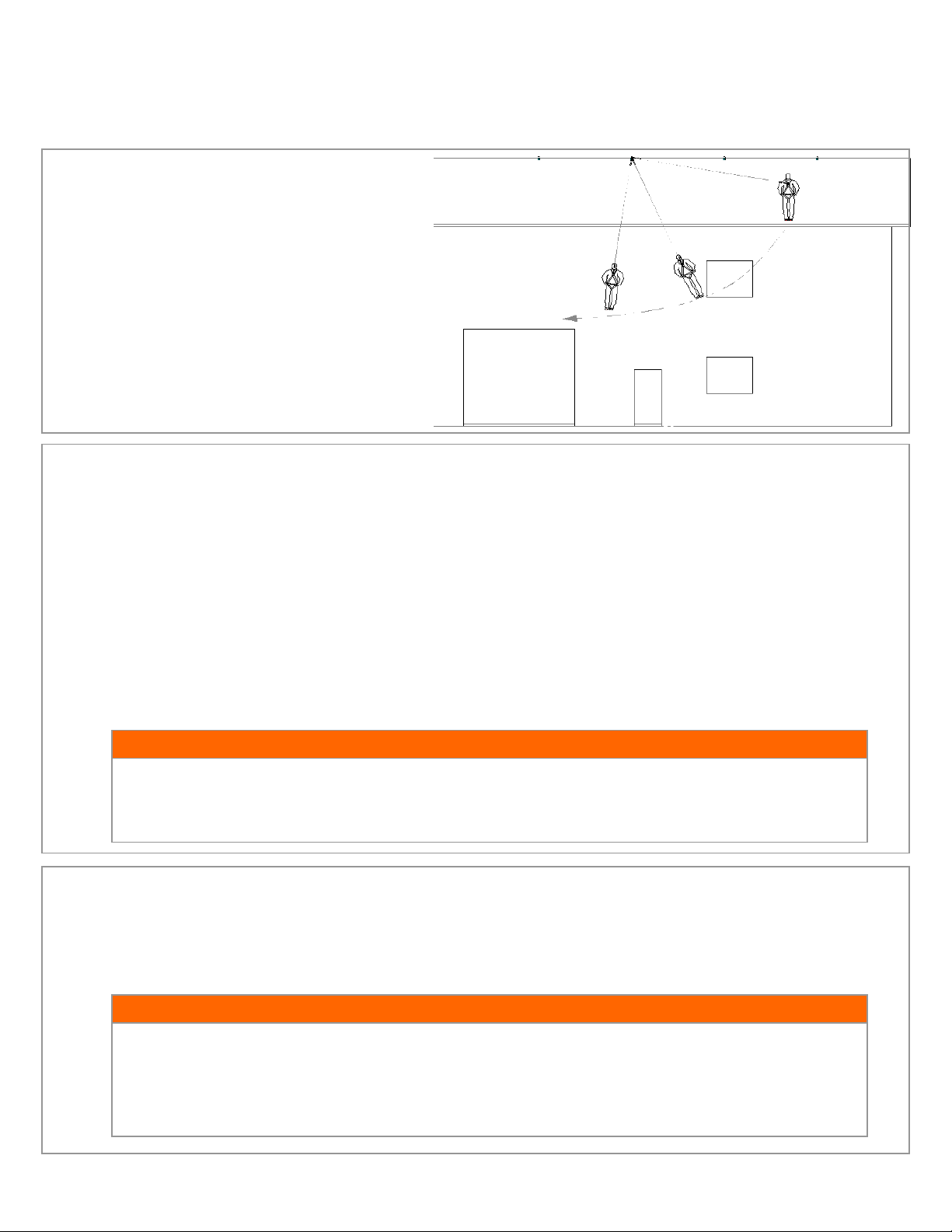
• Swing Falls: Swing falls occur when the anchorage point is not
directly above the point where a fall occurs. The force of striking
an object in a swing fall may cause serious injury or death.
Minimize the risk of swing falls by working as close to the
anchorage point as possible. Do not permit a swing fall if
injury could occur. Swing falls will significantly
increase the clearance required when a self retracting
lifeline or other variable length connecting system is
used.
• Potential Environmental Hazards: Use of fall protection
equipment in areas with environmental hazards may require
additional precautions to prevent injury to the user or damage to
the equipment. Hazards may include but are not limited to:
chemicals, corrosive environments, high voltage power lines,
gases, moving machinery, and sharp edges.
ATTACH TO OVERHEAD
ANCHORS!
SWING FALLS INCREASE
FALL ARREST DISTANCE.
SYSTEM REQUIREMENTS:
• Compatibility of Components: Guardian Fall Protection equipment is designed to be used with Guardian approved
components. Please contact Guardian if you have a question regarding compatibility. Making substitutions without approval
from Guardian Fall Protection may lead to injuries and or death by compromising the safety and reliability of the complete
system. A Qualified person can make a determination on compatibility of equipment from different manufacturers. If in
doubt, please contact Guardian Fall Protection for clarification.
• Compatibility of Connectors: Connectors (D-rings, hooks, carabiners) must be capable of supporting at least 5,000 lbs.
(22kN). Do not use equipment that is not compatible. Non-compatible connectors may unintentionally disengage. Self
locking snap hooks and carabiners are required by ANSI and OSHA. Connectors must be compatible in size, shape, and
strength.
• Making Connections: Only use self-locking snap hooks and carabiners with any Guardian Fall Protection equipment. Do not
use equipment that is not compatible. If you have any questions on compatibility, please call Guardian Fall Protection at
800.466.6385.
LLaarrggee tthhrrooaatt ooppeenniinngg ssnnaapp hhooookkss sshhoouulldd nnoott bbee ccoonnnneecctteedd ttoo ssttaannddaarrdd ssiizzee DD--rriinnggss oorr ssiimmiillaarr oobbjjeeccttss wwhhiicchh wwiillll rreessuulltt
iinn aa llooaadd oonn tthhee ggaattee iiff tthhee hhooookk oorr DD--rriinngg ttwwiissttss oorr rroottaatteess.. LLaarrggee tthhrrooaatt ssnnaapp hhooookkss aarree ddeessiiggnneedd ffoorr uussee oonn ffiixxeedd
ssttrruuccttuurraall eelleemmeennttss ssuucchh aass rreebbaarr oorr ccrroossss mmeemmbbeerrss tthhaatt aarree nnoott sshhaappeedd iinn aa wwaayy tthhaatt ccaann ccaappttuurree tthhee ggaattee ooff tthhee hhooookk..
WARNING!
PERSONAL FALL ARREST INFORMATION:
• Personal Fall Arrest System (PFAS): Personal fall arrest systems used with this equipment must meet applicable state,
federal, OSHA, and ANSI requirements. A full body harness must be worn when this equipment is used as a component of a
personal fall arrest system. As required by OSHA, the personal fall arrest system must be capable of arresting the user’s fall
with a maximum arresting force of 1,800 lbs., and limit the free fall to six feet or less.
If overhead tie off is not feasible, and an approved system has the potential for a free fall greater than six feet,
and up to a maximum of ten feet, Guardian Fall Protection recommends using a personal fall arrest system
incorporating a Guardian Fall Protection Heavy Duty Shock Absorbing Lanyard. The Heavy Duty Lanyard is
designed to keep fall arresting forces below the required standard of 1,800 lbs. Standard type lanyards will
generate impact fall forces in excess of the legal requirement.
WARNING!
Page 4

ANCHORAGE STRENGTH REQUIREMENT:
The anchorage strength required is dependent on the application. Following are anchorage strength requirements for specific
applications. Ensure that any anchorage point used in a personal fall protection system meet the following requirements.
• Fall Arrest: The structure to which the anchorage connector is attached must sustain static loads applied in the directions
permitted by the fall arrest system of at least 3,600lbs. with certification of a qualified person, or 5,000lbs. without
certification. Refer to OSHA and ANSI for specific definition. This anchor is to be used by one worker only. Do not tie off
equipment. Anchorages used for attachment of a personal fall arrest system shall be independent of any anchorage being
used to support or suspend platforms.
• Restraint: The structure to which the anchor point is attached must sustain static loads applied in the directions permitted by
the restraint system of at least 3,000lbs. When more than one restraint system is attached to an anchorage, the strengths
stated above must be multiplied by the number of restraint system attached to the anchorage.
• Work Positioning: The structure to which the anchor point is attached must sustain static loads applied in the directions
permitted by the work positioning system of at least 3,000lbs., or twice the potential impact load, whichever is greater. When
more than one work positioning system is attached to an anchorage, the strengths stated above must be multiplied by the
number of work positioning systems attached to the anchorage.
INSPECTION OF GUARDIAN HARNESSES:
IIff iinnssppeeccttiioonn rreevveeaallss aann uunnssaaffee oorr ddeeffeeccttiivvee ccoonnddiittiioonn,, rreemmoovvee tthhee pprroodduucctt ffrroomm sseerrvviiccee aanndd ddeessttrrooyy iitt iimmmmeeddiiaatteellyy..
WARNING!
• Before each use of this equipment inspect it according to the following guidelines:
A formal inspection of fall protection products/components must be performed at least every six months by a competent
person other than the user. The frequency of formal inspections should be based on conditions of use or exposure. Record
the inspection results in the inspection and maintenance log at the end of this manual.
Inspecting the Harness:
Step 1: Inspect harness components for damage, distortion, cracks, worn parts, corrosion, or wear that might affect integrity.
Step 2: Inspect webbing components for cuts, broken fibers, tears, abrasions, mold, burns, or discoloration. Inspect stitching
for possible breaks and identify any load indicators that might have deployed to indicate a fall. Some harnesses feature
webbing that is protected by material sheaths or coverings. These coverings should be folded back and the webbing
underneath checked for integrity.
Step 3: Inspect webbing retainers, buckles, grommets, and plastic web excess keepers for integrity and function.
Step 4: Inspect labels for legibility. If there is no label attached, contact manufacturer.
Step 5: Inspect impact indicators (if present on back of harness) to determine if product has been impacted in a fall. The
indicator will expose threads and a written warning on the tag will be visible if the product has been involved in a fall. If the
impact indicator has been deployed, remove the product from service.
Step 6: Inspect the system components according to the manufacturer’s instructions.
Step 7: Record the inspection results in the inspection log at the end of this manual.
PLAN THE FALL PROTECTION SYSTEM:
Before installation plan your system. Consider all factors that will affect your safety during use of this equipment. The following
list gives important points to consider when planning your system:
Anchorage: Select a rigid anchorage capable of supporting the loads no less than 5,000 lbs. per worker attached.
Sharp Edges: Avoid working where system components may be in contact with, or abrade against, unprotected sharp edges.
After a Fall: Components which have been subjected to the forces of arresting a fall must be removed from service and
destroyed.
Rescue: The employer must have a rescue plan when using this equipment. The employer must have the ability to perform a
rescue quickly and safely.
WARNING!
Page 5

WARNING!
IMPROPER FIT, ADJUSTMENTS, and ATTACHMENTS CAN RESULT IN SERIOUS INJURY OR DEATH
The proper fit and attachment of full body harnesses is critical for reducing the likelihood of body damage or system failure when
using a compliant fall protection system. Users must be trained and knowledgeable in the proper fit, proper hardware coupling,
and proper harness selection.
• Harness sizing features (chest straps, shoulder straps, leg straps, and any other harness adjustment) must be fitted to each
individual user.
• Harness connections must be made in a compatible manner. Buckles must be positively engaged and secured.
• Compatible connections must be made with connecting equipment (lanyards, lifelines, etc.) only at approved points on the
harness. Never attach snaphooks directly to harness webbing unless specifically designed for such applications (i.e. web
loops substituted for D-rings on some model harnesses).
Dorsal D-rings must be adjusted and situated between the user’s shoulder blades. Chest straps must be located across the
••
chest. Dorsal D-rings may be readjusted by sliding the crossing placard up or down on the webbing to move the D-ring.
ADJUSTING THE HARNESS:
The following requirements outline adjustment mechanisms and locations. Adjustments must allow for a snug, but comfortable fit.
ADJUSTMENT MECHANISMS
Guardian harness models may feature one or more of the following adjustment mechanisms.
1) Pass-Thru Buckles
Adjust Pass-Thru Buckles by sliding the small metal connection through the slot on the
larger metal receiver connection. The buckles will lay flat against one another, creating
enough friction to prohibit the webbing from moving.
2) Tongue Buckles
Tongue Buckles utilize a grommet and framed tongue style receiver to lock
the grommet in place to prohibit slippage.
3) Quick Adjust Friction Buckles
Quick Adjust Friction Buckles incorporate textured rollers mounted inside a
square metal frame. Friction on the roller portion of the buckle prohibits web slippage while allowing
easy adjustment by positioning the roller buckle at a 90 degree angle to the webbing.
4) Sliding Bar Adjusters
Sliding Bar Adjusters allow adjustments to shoulder strap areas by feeding webbing to loosen
or tighten depending on the up or down direction of the buckle. Sliding the buckle down on
the shoulder strap tightens the straps on the wearer, while moving the buckle up on the strap
loosens the shoulder strap webbing.
5) Quick Connect Buckles
Quick Connect Buckles are activated by engaging two release levers simultaneously to
release the male piece from the female receiver. Adjustments are made by feeding
webbing through the male end using a friction style buckle.
ADJUSTMENT LOCATIONS BY HARNESS
The following Guardian harnesses incorporate adjustment mechanisms at the following locations.
HUV Basic Style Harnesses:
Chest Strap Adjustment, Shoulder Strap Adjustments, Leg Strap Adjustments
Construction Style Harnesses:
Chest Strap Adjustment, Shoulder Strap Adjustments, Leg Strap Adjustments, Waist Strap Adjustments
Seraph HUV Style Harnesses:
Chest Strap Adjustment, Shoulder Strap Adjustments, Leg Strap Adjustments
Seraph Construction Style Harnesses:
Chest Strap Adjustment, Shoulder Strap Adjustments, Leg Strap Adjustments, Waist Strap Adjustments
Edge Series HUV Harnesses:
Chest Strap Adjustments, Shoulder Strap Adjustments, Leg Strap Adjustments
Edge Series Construction Harnesses:
Chest Strap Adjustments, Shoulder Strap Adjustments, Leg Strap Adjustments, Waist Strap Adjustments
Lineman Harnesses:
Chest Strap Adjustments, Shoulder Strap Adjustments, Leg Strap Adjustments, Waist Strap Adjustments
Front Loop Cross-Over Harnesses:
Shoulder Strap/Torso Adjustments, Leg Strap Adjustments
Page 6
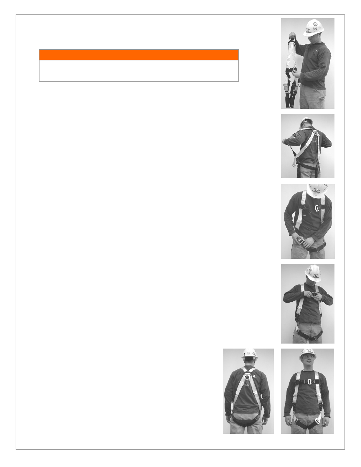
DONNING THE HARNESS:
Step 1: Inspect the equipment for cuts, abrasions, and structural or functional defects. Failure to follow
proper methods of assembly and use can result in serious injury or death. Review inspection criteria above.
IIff iinnssppeeccttiioonn rreevveeaallss aann uunnssaaffee oorr ddeeffeeccttiivvee ccoonnddiittiioonn,, rreemmoovvee tthhee hhaarrnneessss ffrroomm
sseerrvviiccee aanndd ddeessttrrooyy iitt iimmmmeeddiiaatteellyy..
WARNING!
Step 2: Located back D-ring and lift up the harness. Make sure that the straps are not twisted and that all
buckles are unfastened.
• The back (dorsal) D-ring is located where the back webbing straps cross each other and is
held in placed by a placard.
• At this point, no adjustments are made.
• This stage allows users to identify any twisted webbing or disoriented straps.
Step 3: Slip the harness over your shoulders like a jacket. The dorsal D-ring (with the plastic placard)
should be between your shoulder blades.
• Some steps may require initial help from another person.
• Ensure that all straps are oriented correctly, with no twisting or inversion.
• Allow leg straps to hang (do not fasten yet). This step is another opportunity to ensure that no
straps or webbing are twisted.
Step 4: Buckle the leg straps hanging behind you into their front connector on the same side. Adjust to a
tight, but comfortable fit around the thigh.
• A snug fit provides protection during a fall.
• Leg straps should not dangle or hang loose. Loose straps will increase likelihood of injury.
• Leg straps may be Pass-Thru style, Tongue Buckle Style, or Quick Connect Style.
Step 5: Buckle and adjust the chest strap. Chest strap should be located approximately 6 inches from the
top of the shoulders at the lower chest level.
• Chest buckles must not hang below the chest (except for Front Loop Crossover styles)
• Chest buckles should be adjusted for comfortable movement. Excess webbing should be
stowed using provided web keepers.
• Chest buckles may be Pass-Thru style or Quick Connect style.
Step 6: Adjust the shoulder straps (left and right side) to a comfortable fit. Shoulder straps allow vertical
adjustments for height.
• The shoulder straps should be adjusted fit snugly in the shoulders with the leg straps already
fastened.
• The sub-Pelvic (seat) strap should be located comfortably below the buttocks to properly
distribute the force of a fall.
• Shoulder straps may be Quick Adjust Friction buckles or Sliding Bar
Adjusters.
• For Front Loop Crossover Harnesses, adjust the Pass-Thru buckles
below the front loop.
Step 7: For models with a waist belt, fasten the belt so that it fits comfortably
around the waist.
• Waist belts are designed to provide support for work positioning.
• Waist belts incorporate features for utilizing tool bags.
• Waist belts may be Tongue Buckle style or Quick Connect Style.
Page 7
TRAINING:
It is the responsibility of the user and the purchaser of this equipment to assure that they are familiar with these instructions,
trained in the correct care and use of, and are aware of the operating characteristics, application limits, and the consequences of
improper use of this equipment.
TTrraaiinniinngg sshhoouulldd bbee ccoonndduucctteedd wwiitthhoouutt eexxppoossiinngg aannyyoonnee ttoo aa ffaallll hhaazzaarrdd.. TTrraaiinniinngg sshhoouulldd bbee rreeppeeaatteedd oonn aa ppeerriiooddiicc
bbaassiiss iinn aaccccoorrddaannccee wwiitthh yyoouurr oorrggaanniizzaattiioonnss ppoolliiccyy aanndd ccoommpplliiaannccee wwiitthh OOSSHHAA rreegguullaattiioonnss..
WARNING!
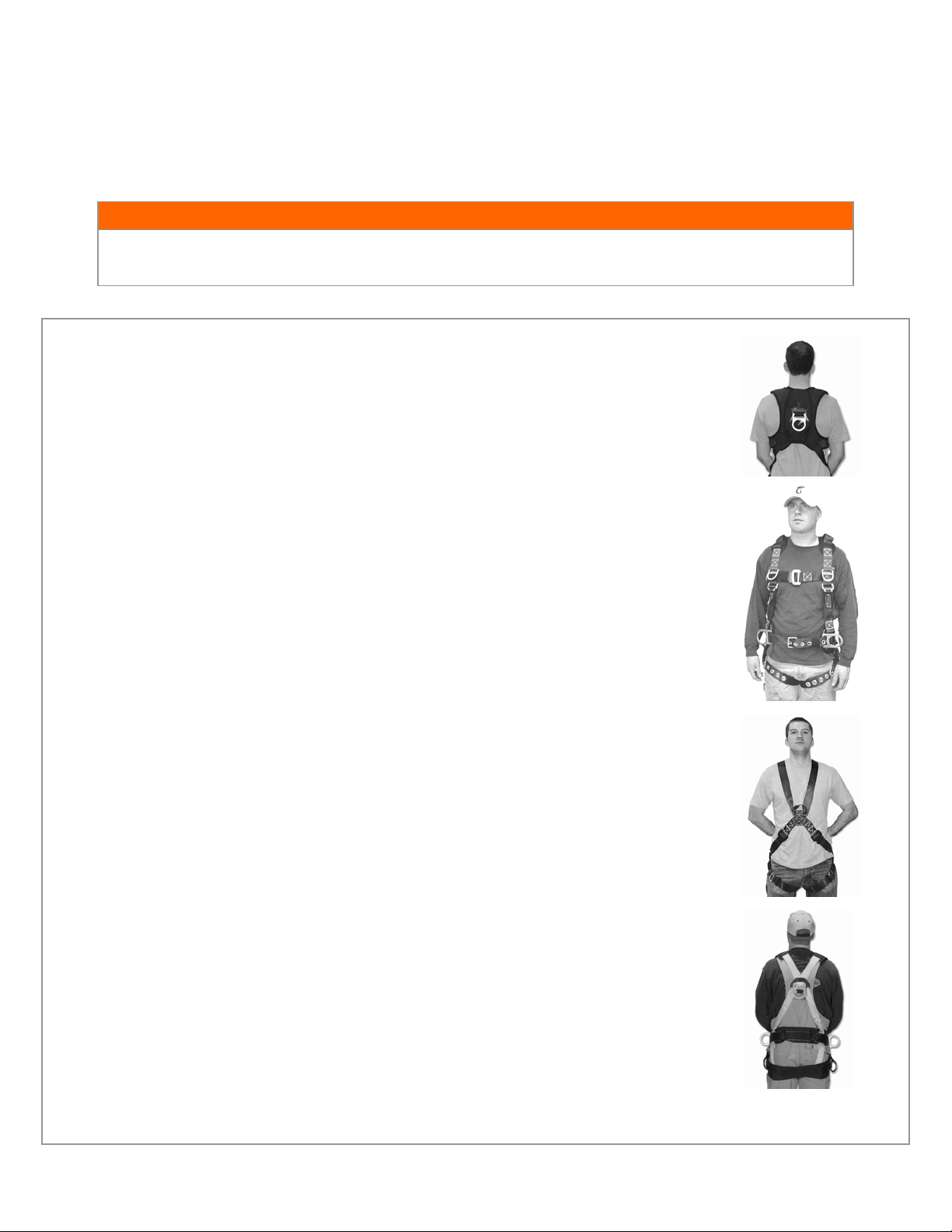
HARNESS ATTACHMENT LOCATIONS/APPLICATIONS:
DORSAL D-RING
• Designed for an approved Fall Arrest or Fall Restraint Attachments
• Example attachments include lanyards or vertical lifelines.
SIDE POSITIONING RINGS
• Designed for use in an approved Work Positioning system.
• Examples attachments include rebar chain assemblies and rebar web assemblies.
SHOULDER OR CHEST RETRIEVAL D-RINGS
• Designed for use in an approved retrieval system and situation.
• Example attachments include retrieval and rescue lanyard yokes.
FRONT CROSSOVER LOOP (FOR FRONT LOOP CROSSOVER HARNESSES)
• Designed for use in an approved ladder system and situation.
• Example attachments include cable grab attachments for ladder or vertical rail systems
CRADLE SEAT D-RINGS
• Designed for use in an approved work positioning system and situation.
• Example attachments include rebar chain assemblies or approved connecting assemblies.
Page 8

SPECIFICATIONS:
Materials:
Polyester Webbing
Steel Hardware
CHEST STRAP:
Correctly adjusted at chest
level.
SHOULDER STRAPS:
Each side adjusted for a
snug, comfortable fit.
WAIST BELT:
Adjusted for a comfortable
fit. Located around waist..
LEG STRAPS:
Each side adjusted for a
snug, comfortable fit.
HARNESS LABELS
GGuuaarrddiiaann FFaallll PPrrootteeccttiioonn,, IInncc..
800-466-6385
th
26513 79
Ave. S.
Kent, WA 98032
www.guardianfall.com
 Loading...