

Page 1
Instructions for the
Assembly and Safe Use of
FramePro Products Multi-Functional Scaffold
Prefabricated Mobile Interior Scaffolds
FramePro Product LLC.
900 Business Park Dr., Suite D
Dixon, Calif. 95620
phone: 707-678-9496
fax: 707-678-9497
© 2007
WHERE TO BEGIN
Page 2
Worksite Inspection
Users of FramePro Scaffolding must walk the area in which they will work, to remove any materials that may be a in the way of the
scaffold setup. Particular care must be taken to note floor hazards such as construction debris, holes in the floor, etc. FramePro
Scaffolds must be used on solid flat surfaces.
Equipment Inspection Prior to use
FramePro Scaffold users must thoroughly inspect the scaffold prior to use. All components must be complete, functioning properly
and correctly assembled. Any incomplete part, missing part, or ill-fitting part should be replaced prior to use. Never use a FramePro
Scaffold without first completely inspecting the unit.
During Use
Keep the platform free from trip hazards. Do not allow loose objects and debris to accumulate on the platform. Make sure the unit is
free from paint, mud, grease or any other hazardous material that may cause you to slip. Never leave the scaffolding unattended.
Following Use
When finished with scaffolding inspect for any damage, deterioration, and any missing parts.
Equipment Maintenance Platforms
Platforms must be checked for loose or missing edge banding, large holes or thin spots where the plywood has been worn. Worn or
damaged boards must be replaced with new boards.
Trusses and Guardrail Sides
Trusses and Guardrail sides must be checked to make sure locking pins are working correctly. Any bent pins or guardrails should not
be used.
Ladders
End Frame Ladders must be inspected for loose or missing caster bushings and stack pins. Casters should be lubricated and checked
before every use.
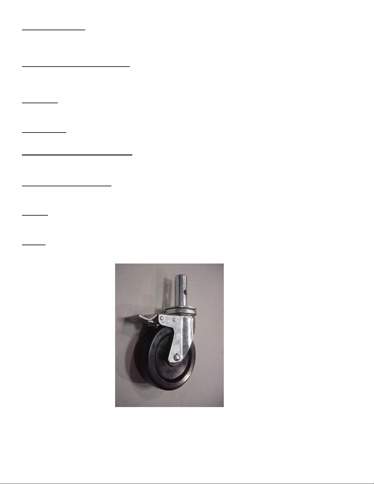
Casters
Casters should be checked for worn or damaged wheels, and missing bearings. Wheels should spin freely and bearing races should
turn freely and smoothly. Axle, bearing should be lubricated often.
Page 3
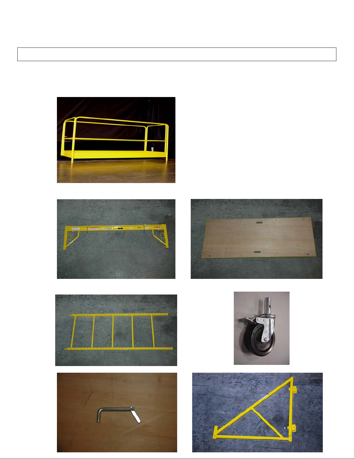
ACCESSORIES
The FramePro Products Multi-Functional
Scaffold is available in Steel and Aluminum
GUARDRAIL SET
MFS TRUSS MFS PLATFORM
MFS LADDERS MFS CASTERS/ PINS
Page 4

MFS GUARDRAIL SAFETY PIN MFS OUTRIGGERS
DANGER
This metal equipment is conductive. Do not use near electrical circuits. Serious injury or death could result.
WARNING
Do not use this equipment if you are in poor health, taking medications, drugs, or drinking alcoholic beverages, all of which may impair
your ability to work safely on this product.
Do not mix platforms, casters, trusses, end frame access ladders or other components from other manufacturers with FramePro
scaffolding. Component dimensions differ enough to be hazardous when mixed. Use only authorized FramePro parts and components.
Discard the scaffold if it has been exposed to fire or corrosive chemical.
Do not overreach. Keep your body within the boundaries of the guardrail and scaffold section.
Do not stand on guardrail or use any components of the guardrail to gain additional standing height.
Do not place ladders, chairs, boxes or any other such object or device on the platform to gain addition a l standing height.
Do not try to pull or “scoot” yourself from one location to another while standing on platform. Climb down from the platform to the
floor. Mount and dismount the platform from the top center of the End Frame Access Ladder. Do not swing around the side of the
ladder. Unlock the casters and move the scaffold in a safe manner. Relock the casters before climbing to the working platform. For
easier locking and unlocking of the casters, turn the brake levers outward.
Do not subject the FramePro scaffold to any side-load forces or im pact s.
Do not place a FramePro on the deck of a scissor-lift or any other type of access equipment in order to gain additional standing
height.
Guardrails must be used at working platform heights of 6 ft. or higher.
(Refer to OSHA 1910.28, 1910.29, and ANSI A10.8) Check with state and local codes and regulations for variance from federal
standards.
Before units are to be stacked, a set of four (4 ) Outriggers ( PN MFS-NOR , MFS-WOR )
Must be installed on the base section of scaffolding. Insert casters form a section of scaffolding to be stacked into the outriggers prior
to installation. Do not stack more than three (3) sections high (18 ft./ 5.5 m). Once the scaffold is in the desired position on the jobsite
floor, lock the casters on the scaffold tower and all four outriggers.
All lock pins must be engaged before using scaffold. Lock nut screws onto threaded nipple after scaffold assembly and platform height
adjustment. DO NOT HAMMER LOCK PINS. If locks stick, clean and grease lightly. Move back and forth to free movement.
CAUTION
-The truss channels within which the platforms are secured in place, should be inspected prior to use. Any debris, accumulation of
drywall mud, etc. must be removed prior to use. After placing the platform within the truss channels, always inspect to see that the
platform is properly seated into place.
Page 5

-Always lock the brakes on scaffold casters before climbing the End Frame Access Ladders. For easier locking and unlocking of the
casters, turn the brake lever outward. The lever on the casters is to be pressed down until it locks the wheel
-The maximum Distributed Load of a FramePro Scaffold Tower decreases with the number of sections that are stacked.
Base Only 1,000 lbs.
2 Sections 850 lbs.
3 sections 700 lbs.
1. Invert an End Frame Access Ladder. Insert
the casters into the ladder leg bushings, pressing the casters into the bushing by hand
until the hole in the caster stem lines up
with the hole in the scaffold ladder- attach
with safety pins. Repeat this process
for the second End Frame Access Ladder.
ASSEMBLY INSTRUCTIONS
` 2. Turn the End Frame Access Ladder over so that it rests on its casters. Holding an End Frame
Access Ladder with one hand, engage one truss to the ladder leg. Note: The locking pin on
the truss should be disengaged and free to be pushed back and forth. Depress the thumb plate
of the truss lock and align the pin to a predetermined hole in the ladder leg. Release the thumb
plate to engage the spring- loaded Positive Engagement Lock.
3. Hold the second End Frame Access Ladder
with one hand. Repeat Step 2 to attach the
other end of the truss to the second End Frame
Access Ladder.
4. Attach the second truss to the partially
assembled scaffold. Make sure both trusses
are the same height and parallel to the floor.
Do not screw the knurled thumb plate onto
the threaded nipple of the Positive Engagement Lock yet. The spring-loaded pin, when
properly positioned in the ladder leg holes,
will hold the truss in place.
5. Complete the assembly by laying the platform
in place, resting it securely within the platform
ledges of each truss channel. No metal platform
banding should be visible above the vertical lip
Page 6

of the truss channel. Make sure the platform ledges on the truss channel are thoroughly cleaned
and free of debris that would prevent the platform
form seating properly into the trusses.
6. To adjust the platform height move to one end of the scaffold and grasp both Positive
Engagement Locks on the trusses. Depress both thumb plates, pushing the pins out of
the holes in the ladder legs. The trusses are now free to move either up or down on the
ladder frame to the desired platform height. Following height adjustment, release the
thumb plates and allow the spring-loaded pins to engage the nearest ladder leg hole. For
added security tighten pin as shown in picture above.
7. Screw the knurled thumb plate onto the threaded nipple
of the Positive Engagement Lock to positively prevent
the pin from backing out of the hole. Repeat Steps 6-7
at the opposite end of the scaffold making sure the tru sses are at the same height and parallel to the floor. Check
again to see that the platform is properly secured within
the truss channels.
Assembly of the Guardrails
WARNING
Guardrails shall be used at working platform heights of 6 foot
or higher. ( OSHA 1910.28, 1910.29, AND ANSI A10.8 )
Check with state and local codes or private company directives for
variances which may be more restrictive than federal codes.
1.) Install guardrails by inserting four corner pegs in their corresponding receivers. Insert safety pins to
keep it in place. Make sure end gates are ALWAYS closed and locked when not being actively used.
Page 7

2.)Rail will feel “loose” this is normal. Pull gently up to ensure proper locking.
Assembly of the Outriggers
WARNING
Before scaffold units are to be stacked, a set of (4) Outriggers (MFS-
NOR, MFS-WOR) with casters shall be installed on the base section
of scaffolding. (OSHA 1910.29) The casters must be the same size as
the casters in the base scaffold
.
1. Insert a caster into each 2. Attach one Outrigger (with caster) 3. Lock the casters on the
Outrigger. Casters used in to each of the four (4) ladder legs Outriggers each time
the Outriggers must be the of the base scaffold section. you lock the casters on
same size as the casters used Lock them into place by using the base scaffold. This
in the base scaffold. (2) safety snap pins. is to be done prior to
the same size as the ca- to climbing the tower.
sters used in the base For easier locking and
scaffold. unlocking of the casters,
turn the brake lever outward.
Assembly of a FramePro Scaffold Tower
CAUTION
Do not erect a free-standing FramePro Scaffold Tower more than three
(3) Sections high. Use a team of at least two (2) persons to erect a
FramePro Scaffold Tower – one on the ground handing up components
and a second person on the tower installing the components.
1. Assemble a Basic FramePro Scaffold base by following
the instructions in this booklet
.
2. Install a set of four (4) outriggers on the base section if
3. you are planning on stacking the MFS more than its
single height. by following the instruction in this booklet.
4. Lock the casters on the scaffold and four (4) outriggers
Page 8

before proceeding. For easier locking and unlocking
of the casters, turn the brake levers outward.
5. One person climbs onto the platform of the
Base scaffold. From the ground, the second
person hands up components of the first stacked section
.
6. Install the two (2) End Frame Access Ladder. First, then install the two (2) side Trusses at the desired platform height. Lock
all four (4) Positive Engagement Locks on the Trusses
7. Install the platform securely within the platform Ledges of the truss channels.
.
8. While moving from one platform to another, it is
neccessary, to carefully step around the End Frame
Access Ladder, to the outside of the ladder. Keep
your body close to the ladder at all times during
this move.
scaffold section and the four outriggers must be locked
prior to this movement. For easier locking and
unlocking of the casters, turn the brake levers outward.
REMEMBER: All casters in the base
9. Repeat Steps 4-8 if another section is to
be stacked ( not to exceed 3 high ). When
necessary, use a rope to bring up components
from the person on the ground
.
Page 9

Complete sections with platforms should be stacked. Each stacked section includes two ( 2 ) End Frame
Access Ladders two ( 2 ) adjustable trusses, and one ( 1 ) platform.
To get maximum height from a FramePro Products Multi-Functional Scaffold set trusses just below the
top of the ladders.
DO NOT roll a FramePro Scaffold tower when workers is on the platform
Climbing A FramePro Mobile Scaffold
Lock All Casters before Climbing The Scaffold
Before climbing the scaffold, lock all four (4) casters on the base section of the scaffold. Also lock all outrigger casters if outriggers
have been installed on the base section. DO NOT CLIMB a FramePro Mobile Scaffold when the casters are unlocked. For easier
locking and unlocking of the casters, turn the brake levers outward.
Keep Your Body Close to the Scaffold As You Climb
Page 10

Mount and dismount the platform from the top center of the End Frame Access Ladder. Do not swing around the scaffold. Do
not try to pull or “scoot” yourself from one location to another while standing on the platform. Climb down from platform to
the floor. Unlock the casters and move the scaffold in a safe manner. Relock the casters before climbing up to the working
platform. For easier locking and unlocking of the casters, turn the brake lever outward.
 Loading...