

Page 1

Information classified Confidential
-
Do not copy (See last page for obligations)
QPRO Technical Data Sheet
1137-0901
Revision A
ONFIDENTIAL
C
Document Number 1137-0901 Rev: A .
Page 2
QPRO Technical Data Sheet
REV ECO#
REASON
DATE
Information classified Confidential
-
Do not copy (See last page for obli
gations)
Revision History
Rev. A 00261 Initial Production Release
Representante autorizado no Brasil:
Hidromec Indústria e Comércio Ltda
Rua Sacadura Cabral - 351
Rio de Janeiro RJ
Fone: + 55 21 3622 8000
ONFIDENTIAL
C
0572-11-2244
07898945973014
(01) 07898945973014
Document 1137-0901, REV A ii
Page 3

QPRO Technical Data Sheet
Table of Contents
1 Introduction .................................................................................................................... 1
1.1
O
VERVIEW
1.2
C
ONTROL OPTIONS
1.3
R
EFERENCE MANUALS
1.4
D
EVELOPMENT KITS
1.5
C
ONTACTING
2 QPRO Hardware ........................................................................................................... 3
2.1
QPRO A
2.2
S
YSTEM OVERVIEW AND SIGNAL DESCRIPTIONS
2.3
I
NPUT POWER
2.3.1 Internal Power Supply Description ........................................................................................... 4
2.3.2 External Power Supply Requirements ..................................................................................... 5
2.3.3 Load Dump Protection ............................................................................................................. 5
2.3.4 Typical Power Consumption .................................................................................................... 5
2.3.5 Power Calculation ................................................................................................................... 6
2.4
C
ONNECTOR INFORMATION
3 Modem Wireless Communication .................................................................................. 9
3.1
G
LOBAL POSITIONING SYSTEM
3.2
G
LOBAL SYSTEM FOR MOBILE COMMUNICATIONS
3.3
ORBCOMM ................................................................................................................... 10
3.4
IRIDIUM-S
3.5
G
LOBALSTAR
4 Customer Input/Output Interfaces (External) ............................................................... 12
4.1
A
NALOG INPUTS
4.1.1 Sample Circuits for appropriate Scaling to 0-3.5V .................................................................. 12
4.2
D
IGITAL INPUTS/OUTPUTS
4.2.1 Switched Digital Relay ........................................................................................................... 14
4.3
J1939 ............................................................................................................................ 15
4.4
3.5V P
4.5
RS-232 P
4.6
I
NTERFACE CONNECTOR ELECTRICAL SPECIFICATION
4.7
C
USTOMER INTERFACE (INTERNAL
4.7.1 Memory ................................................................................................................................. 17
4.7.2 Real-Time Clock (RTC) ......................................................................................................... 17
4.8
E
NVIRONMENTAL CONSIDERATIONS
5 QPRO Data Interface Specifications ........................................................................... 19
5.1
D
ATA INTERFACES
5.2
E
NVIRONMENTAL SPECIFICATIONS & CERTIFICATIONS
5.3
C
ERTIFICATIONS
5.4
GSM/GPRS M
5.5
C
OMMUNICATIONS
5.6
I
NTEGRATED
5.7
A
PPLICATION INTERFACE
5.8
C
OMMUNICATIONS
5.9
C
OMMUNICATIONS IRIDIUM
5.10 P
5.11 O
5.12 P
OWER
PERATION MODES
HYSICAL SPECIFICATIONS
........................................................................................................................ 1
........................................................................................................... 1
...................................................................................................... 1
.......................................................................................................... 1
QUAKE ....................................................................................................... 2
VAILABLE CONFIGURATIONS
................................................................................................................... 4
............................................................................................... 7
HORT BURST DATA
.................................................................................................................. 11
.............................................................................................................. 12
............................................................................................... 13
OWER
.................................................................................................................. 15
ORTS (GENERAL
.......................................................................................................... 19
............................................................................................................. 19
ODULE- QUAD BAND
GSM ................................................................................................. 19
GPS C
ORBCOMM ....................................................................................... 20
.......................................................................................................................... 20
........................................................................................................ 20
) ............................................................................................. 15
HIP SET
............................................................................................ 19
................................................................................................. 19
.............................................................................................. 20
.............................................................................................. 20
................................................................................. 3
................................................................. 4
(GPS) ................................................................................ 9
(GSM) .................................................... 9
(SBD) .............................................................................. 10
....................................................... 15
) .................................................................................. 17
................................................................................. 17
....................................................... 19
................................................................................. 19
Document 1137-0901, REV A iii
Page 4

QPRO Technical Data Sheet
Information classified Confidential
-
Do not copy (See last page for obligations)
6 QPRO Drawings .......................................................................................................... 21
7 QPRO Recommended Installation Guidelines ............................................................. 24
7.1
7.2
QPRO M
A
NTENNA RECOMMENDATIONS
OUNTING RECOMMENDATIONS
........................................................................................ 24
........................................................................... 24
8 Frequently Asked Questions ....................................................................................... 25
9 Declaration of Conformity ............................................................................................ 26
ONFIDENTIAL
C
Document 1137-0901, REV A iv
Page 5

QPRO Technical Data Sheet
List of Figures
Figure 2-1, Available QPRO Configurations .................................................................................................. 3
Figure 2-2, QPRO System Block Diagram for Fully Loaded Configuration .................................................... 4
Figure 2-3, Connectors on QPRO................................................................................................................. 8
Figure 4-1, Analog Input Circuit .................................................................................................................. 12
Figure 4-2, Sample 12V Sensor ................................................................................................................. 13
Figure 4-3, Sample 24V Sensor ................................................................................................................. 13
Figure 4-4, Sample 24V Sensor ................................................................................................................. 13
Figure 4-5, Digital Input Circuit ................................................................................................................... 14
Figure 4-6, Switched Relay Characteristics ................................................................................................ 14
Figure 6-1, Dimensions for QPRO .............................................................................................................. 21
Figure 6-2, Interface Connector for QPRO .................................................................................................. 22
Figure 6-3, QPRO Development Kit Cable .................................................................................................. 23
List of Tables
Table 2-1, Input Power ................................................................................................................................. 5
Table 2-2, QPRO Power Consumption ......................................................................................................... 5
Table 2-3, Connector Types for Each Product .............................................................................................. 7
Table 2-4, Connector Information ................................................................................................................. 7
Table 3-1, Cable Loss Guidelines ............................................................................................................... 11
Table 4-1, Interface Connector Electrical Specifications/RF Connections .................................................... 16
Table 4-2, User Flash and RAM Availability ................................................................................................ 17
ONFIDENTIAL
C
Document 1137-0901, REV A v
Page 6

QPRO Technical Data Sheet
Information classified Confidential
-
Do not copy (See last page for obligations)
This page intentionally left blank
ONFIDENTIAL
C
Document 1137-0901, REV A vi
Page 7
QPRO Technical Data Sheet
Ref Doc Number
Part Number
Recommended Reference Manuals (Name)
8 QUAKE 1135
-
4715 QCP, QUAKE Communication Protocol, Manual
9 QUAKE
1135-4711 QUAKE Co
nfiguration Tool Manual
Information classified Confidential
-
Do not copy (See last page for obligations)
1 Introduction
1.1 Overview
Welcome to the QUAKE™QPRO Satellite + GPRS/GSM Global Communication modem! The QUAKE
QPRO is a complete IP67 enclosed solution ready for global use. The QPRO is designed to communicate
with GSM terrestrial network systems when a cell signal is available, and to slide seamlessly into its back-up
mode and communicate with a Satellite System when a cell signal is not available. Besides this advanced
modem functionality, the QPRO has additional processing power, memory, and I/Os that allow sophisticated
customer applications to run within the modem. Using an integrated power regulator, the QPRO is designed
to operate over a 6-32 volt input range. It has been specifically designed to meet the demanding
requirements of vehicular environments and directly supports communication over a vehicle bus using the
SAE J1939 standards. These features make the QPRO an ideal stand-alone solution for a large variety of
applications including transportation, oil and gas and heavy equipment markets.
This Data Sheet presents an overview of the QPRO technology, device specifications, integration guidelines,
and basic information on configuring and programming. Additional QUAKE manuals, including the User’s
Guide to Q4000/QPRO, P/N 1135-4713, can be accessed on our website or by contacting QUAKE Customer
ONFIDENTIAL
C
Support at http://QUAKEglobal.com/support/.
1.2 Control Options
The QPRO has the option of running in standalone mode or QUAKE Communications Protocol (QCP)
mode.
In standalone mode, the user’s application resides directly on the modem. QUAKE provides three sample
applications as part of the Development Kit to help users create, build and run their own custom applications.
QCP mode is used to send data via GSM/GPRS, or a single Satellite System such as Orbcomm, Iridium or
Globalstar. Customers who use the Q4000/QPRO in this mode typically have a processor, and the
necessary I/O for their specific applications, and use the Q4000/QPRO as a modem only, or to add
functionality such as addition I/O’s, GPS, etc. The QUAKE Communication Protocol (QCP) is used to
communicate between the QPRO and the application.
1.3 Reference Manuals
In the case of Orbcomm, OSI protocol pkt was received from the SCCS.
1 Orbcomm E80050015 Orbcomm Serial Interface Specification
2 Orbcomm A80TD0008 Orbcomm System Overview
3 Orbcomm A80MK0019 Orbcomm Messaging Services Description
4 QUAKE 1135-4713 User’s Guide to Q4000/QPRO
5 QUAKE 1135-3001 QUAKE API Reference Manual
6 QUAKE 4000-3000 Iridium SBD AT Command Set Manual
7 Iridium SBD, Developer’s Guide
1.4 Development Kits
QPRO Development Kits are available from QUAKE. They include: Development Environment (IAR)
Compiler, QUAKE libraries and header files, sample application programs, QPRO modem, necessary
cables, antennas, and all documentation. Contact your QUAKE sales personnel for more details.
Document 1137-0901, REV A 1
Page 8

QPRO Technical Data Sheet
1.5 Contacting QUAKE
If you need to contact QUAKE Global regarding the QPRO Development Kit or other issues, please refer to
the following information:
QUAKE Global Inc.
9765 Clairemont Mesa Blvd, Suite A
San Diego CA 92124
Phone Number: (858)-277-7290 Fax Number: (858) 277-7259
Website: www.QUAKEglobal.com
Submit a Customer Support Ticket: http://QUAKEglobal.com/support/
Document 1137-0901, REV A 2
Page 9
QPRO Technical Data Sheet
2 QPRO Hardware
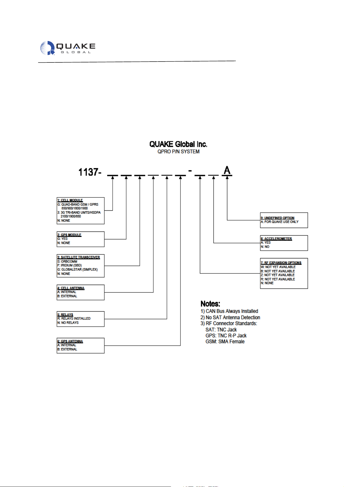
2.1 QPRO Available Configurations
As an “off the shelf” product, the QPRO is available in various standard configurations. For volume
applications, the QPRO may be ordered in an almost unlimited number of configurations. QUAKE prides
itself on the flexibility of the products we provide to our customers. If you need a customized configuration,
please contact your QUAKE Global Sales Representative for details.
ONFIDENTIAL
ONFIDENTIAL
C
C
Figure 2-1, Available QPRO Configurations
*The 8MB Memory Size option contains approximately 4 MB of User Flash and 8 MB of RAM
Information classified Confidential - Do not copy (See last page for obligations)
Document 1137-0901, REV A 3
Page 10
QPRO Technical Data Sheet
Information classified Confidential
-
Do not copy (See last page for obligations)
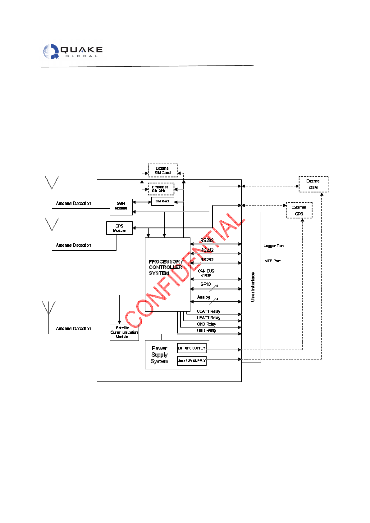
2.2 System Overview and Signal Descriptions
The following System Block Diagram describes the basic functional blocks of the QPRO:
Figure 2-2, QPRO System Block Diagram for Fully Loaded Configuration
2.3 Input Power
2.3.1 Internal Power Supply Description
The QPRO contains the required internal regulation and reverse bias/overvoltage protection to meet J1455
specifications for 12VDC and 24VDC systems. DC power of +6VDC to +32VDC is supplied through pin 1
(BATT+) and pin 2 (GND) of the multi-pin connector. The ground pins are connected directly to the chassis of
the QPRO. It is recommended that the power supply feeding the QPRO be protected with a fast-blow fuse
Document 1137-0901, REV A 4
Page 11
QPRO Technical Data Sheet
Function
Typical
Typical
Typical
Typical
Typical
Typical
Typical
Typical
Notes
ORBCOMM
Information classified Co
nfidential
-
Do not copy (See last page for obligations)
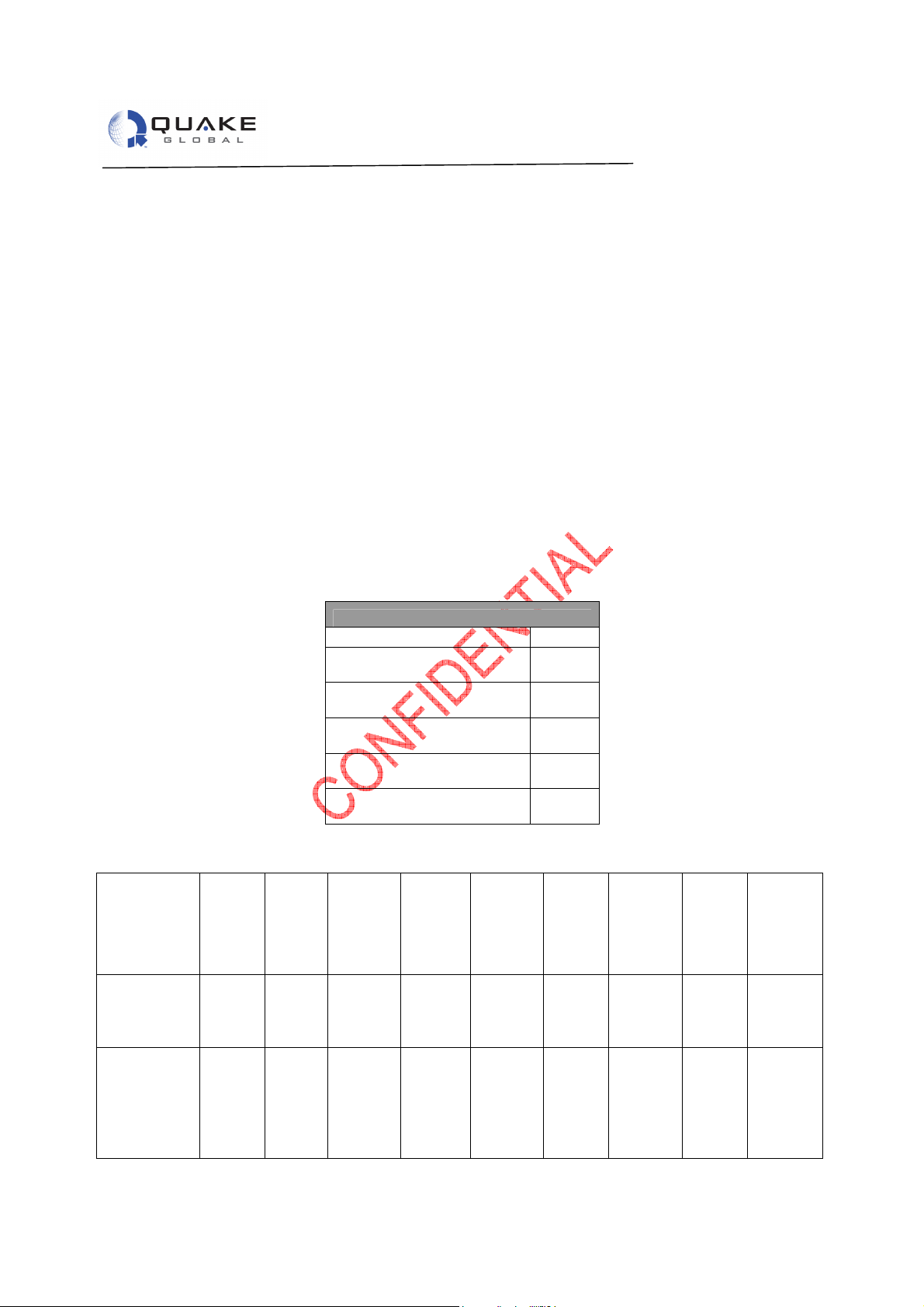
sized appropriately per the expected current draw as shown Table 2-1, Input Power Current draw is
dependent on the features and options that are installed and operating. See Table 2-2, , for typical power
consumption.
2.3.2 External Power Supply Requirements
In order for the modem to boot properly:
1) The supply voltage must be below 1.4 volts for 4 seconds before re-applying the 6 to 32 V.
2) The rise time on the supply voltage must be 10ms maximum, from 0 to 6Vdc.
2.3.3 Load Dump Protection
To pass the load dump testing requirement of the J1455 specification, there must be a minimum of two 33V
diodes placed in parallel between power and ground of the input power supply. This functionality has been
built into the QPRO.
2.3.4 Typical Power Consumption
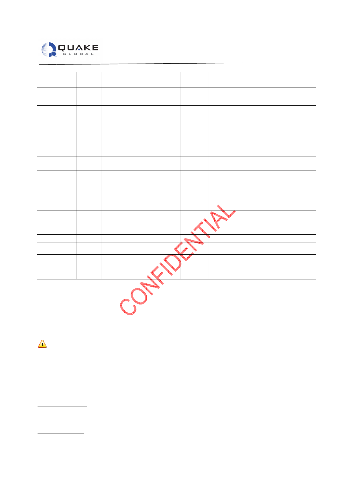
This section describes the typical power consumptions of each component of the QPRO modem. Table 1 is
a listing of the required input voltage limits and Table 2 gives a break down of the different components of
the QPRO.
Table 2-1, Input Power
ONFIDENTIAL
C
Minimum Input Voltage Requirements
Units Volts
ORBCOMM
IRIDIUM
Processor Only
GSM/GPRS
GPS
10.5 to
32
7.5
6
6
6
Table 2-2, QPRO Power Consumption
Activated
TX
Current
@6V
(Amps)
.000050
.093
.072
N/A N/A 1.900 22.800 0.950 22.800 0.700 22.400 ~3 mS
Power
@6V
(Watts)
.00003
.558
.432
Current
@12V
(Amps)
0.000025
0.045
0.035
Power
@12V
(Watts)
.0003
.54
.42
Current
@24V
(Amps)
0.000012
.023
.0185
Power
@24V
(Watts)
.000029
.552
.444
Current
@32V
(Amps)
0.000009
.017
.0145
Power
@32V
(Watts)
.000029
.544
.46
ACQ, 38
mS COM
800mS
Bursts
and
RSV
Document 1137-0901, REV A 5
Page 12
UARTs and
CAN bus ON
UBATT
GND Relays
GSM
GSM
GPS
GSM RX
GSM TX low
GSM TX high
IRIDIUM RX
IRIDI
UM TX
GlobalStar
GlobalStar
TX
Burst
Relays ON
ON
External 3.3V
External 3.3V
pwr
pwr
Idle
QPRO Technical Data Sheet
0.035 0.21 0.018 0.216 0.009 0.216 0.004 0.128 iQ + Bus
ON
2.000 12.00 2.000 24.000 2.000 48.000 2.000 64.000 Maximum
rating on
relays
2.000 12.00 2.000 24.000 2.000 48.000 2.000 64.000 Maximum
rating on
relays but
not part
of system
power.
0.34 2.04 0.165 1.980 0.110 2.640 0.080 2.560 Maximum
rating
0.098 0.59 0.048 0.576 0.023 0.552 0.017 0.544 Maximum
rating
0.025 0.15 0.013 0.156 0.027 0.648 0.021 0.672
0.065 0.39 0.032 0.384 0.010 0.240 0.008 0.240 4 Slot DL
0.33 1.98 0.160 1.920 0.080 1.920 0.060 1.920 GPRS 4
slots
(Class
10)
1.35 8.10 0.650 7.800 0.325 7.800 0.245 7.840 GPRS 4
slots
(Class
10)
0.168 1.01 0.085 1.020 0.042 1.008 0.031 0.992
N/A N/A 0.950 11.400 0.470 11.280 0.350 11.200 8.33 mS
burst
###### ###### 1.5E-06 ####### 7.5E-07 ###### 5.6E-07 ###### Between
TX burst
0.198 1.19 0.095 1.140 0.038 0.912 0.028 0.896 1.44 S
Note: All currents below are individual contributions and at 25°C ambient. Total current is the sum of each.
Items with burst or slot in the notes are the peak values.
* - Use of ORBCOMM and Iridium satellite network is not available when modem’s voltage drops below 10.5
VDC.
** - Relay current is 1A MAX at 25C, .5A MAX at 85C. Power usage depends on customer
application.
DC Input power to QUAKE QPRO modems is +6.0V to +32.0VDC. Supplied input voltages outside this
range will result in damage to the modem and void the warranty.
2.3.5 Power Calculation
Depending on the configuration of the modem, add the appropriate power. For example:
QPRO with GSM, GPS and ORBCOMM with no messages being sent:
Current Calculation:
0.045 A (Processor Only) + 0.020 A (GSM RX) + 0.010 A (GPS) + 0.035 A (ORBCOMM RX)
= 0.11 A or 110 mA
Power Calculation:
0.54 W (Processor Only) + 0.24 W (GSM RX) + 0.12 W (GPS) + 0.42 W (ORBCOMM RX)
= 0.11A * 12 V = 1.32 W
Document 1137-0901, REV A 6
Page 13
QPRO Technical Data Sheet
Sat
QPRO
GPS
QPRO
GSM
Interface
OEM Module
Customer Interface
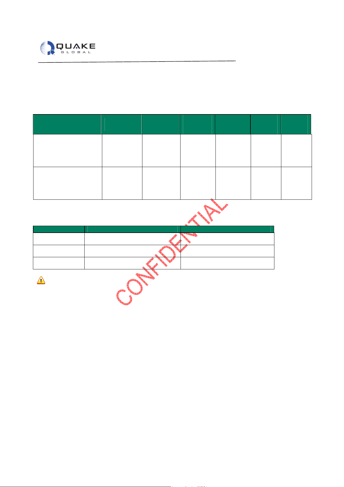
2.4 Connector Information
Table 2-3, Connector Types for Each Product
Product
QPRO
Orbcomm/GPS/Cellular
QPRO
Iridium/GPS/Cellular
Locking Tyco 1-776163-1 Tyco 776164-1
Pins - Tyco 770520-3
Crimping Tool
ONFIDENTIAL
C
If the 3.3 V Continuous Output Power pins are not being used, do not lead wires out of connector.
Connecting these pins to an external supply will damage the modem and void the warranty.
QPRO Sat
Connect
Orbcomm
SMA-Female
Iridium SMAFemale
Table 2-4, Connector Information
- Tyco Hand tool 58440-1
Antenna
Connect
Orbcomm
SMA-Male
Iridium
SMA-Male
GPS
Connect
GPS
Reverse
Polarity
SMAMale
GPS
Reverse
Polarity
SMAMale
Antenna
Connect
GPS
Reverse
Polarity
SMAFemale
GPS
Reverse
Polarity
SMAFemale
GSM
Connect
GSM
SMA
Female
GSM
SMA
Female
Antenna
Connect
GSM
SMAMale
GSM
SMAMale
Information classified Confidential - Do not copy (See last page for obligations)
Document 1137-0901, REV A 7
Page 14
QPRO Technical Data Sheet
Satellite
Connector
GPS
Connector
GSM
Connector
ONFIDENTIAL
C
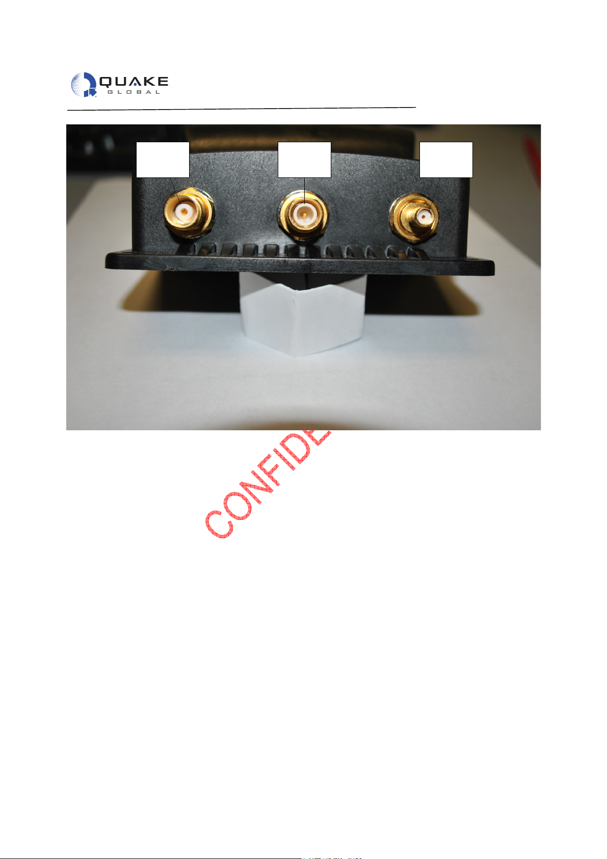
Figure 2-3, Connectors on QPRO
Information classified Confidential - Do not copy (See last page for obligations)
Document 1137-0901, REV A 8
Page 15

QPRO Technical Data Sheet
Information classified Confidential
-
Do not copy (See last page for obligations)
3 Modem Wireless Communication
3.1 Global Positioning System (GPS)
• Internal GPS
o Performance
22-channel GPS chipset.
Rapid Time-To-First-Fix (TTFF) 38 seconds from a Cold Start, 25 seconds from
warmstart, 2 seconds from hotstart (Depending on antenna and signal strength)
Accuracy within 2.5 meters
Updates raw location data every 1 second
Sensitivity: -160 dBm for tracking and -146 dBm for acquisition
o Features
Antenna detection
Utilizes a passive or active 3.0-3.5VDC (5-30 mA nominal) GPS antenna (Active
recommended).
Active antenna with 20-30 dB gain @ 3.3 VDC. Max noise figure 1.5 dB
• External GPS
o GPS Serial Port – If there is no internal GPS, the RS-232 serial port can be used to interface
to an external GPS module or for other application needs.
Pins: 7(Rx), 8 (Tx), and GND (Pin 9, 12, 26 or 35).
NMEA 0183 data available externally on Pin 7, GPS_TX_RS232
ONFIDENTIAL
ONFIDENTIAL
C
Do not feed voltage into or short the GPS port to ground. The QPRO supplies DC bias voltage on the
C
antenna center conductor. Violating this warning may cause damage to the unit and void the warranty.
• 9600 Baud, 8 bits, no parity bit, 1 stop bit
• Updates location data every 1 second
3.2 Global System for Mobile Communications (GSM)
• Internal GSM
o Performance
Transmit Output Power 2W (Class 4) for 850/900 bands
1W (Class 1) for 1800/1900 bands
Sensitivity -107 dBm @ 850/900 MHz
-106 dBm @1800/1900 MHz
o Features
Band (Quad Dual Band)
• GSM850 (TX: 824.2~ 848.8 MHz/ RX: 869.2 ~ 893.8 MHz)
• EGSM900 (TX:890.0 ~ 914.8 MHz/Rx: 935.0 ~ 959.8 MHz)
o (TX:880.2 ~ 889.8 MHz/Rx: 925.2 ~ 934.8 MHz)
• DCS-1800 (TX:1710.2 ~ 1784.8 MHz/Rx: 1805.2 ~ 1879.8 MHz)
• PCS-1900 (TX:1850.2 ~ 1909.8 MHz/Rx: 1930.2 ~ 1989.8 MHz)
TCP/IP stack
• IP, TCP, SMTP, FTP, UDP, SMS, POP protocols.
92 kbps maximum continuous throughput
Antenna detection (see note below)
In order for the antenna detection circuitry to work properly, the GSM/GPRS antenna that is selected
must have a 10Kohm DC resistance. This type of antenna can be obtained through the following antenna
Document 1137-0901, REV A 9
Page 16

QPRO Technical Data Sheet
Information classified Confidential
-
Do not copy (See last page for obligations)
manufacturers: Taoglas, Hirschmann Car Communications, and Tyco Electronics.
• External GSM
o GSM Serial Port - A QPRO that DOES NOT include an internal GSM module has an option
to use an RS-232 serial port to communicate with an external GSM module, or it can be
used as an additional serial port with the use of a custom application. For example, the AUX
Port could be used for an External GSM:
Pins: 5 (Rx), 6 (Tx), and GND (Pin 9, 12, 26, or 35).
Use only approved GSM antennas
3.3 ORBCOMM
• Internal
o Performance
Transmit Output Power: 5 watts Minimum, 10 watts Maximum
Sensitivity -123 dBm with typical BER 1x10⁻⁵
ONFIDENTIAL
C
• External
o Features
Uplink (Tx)
• 148-150.05 MHz
• 2400 baud
Downlink (Rx)
• 137-138 MHz
• 4800 baud
Optional antenna detection
o MTS Serial Port- The Main Transport Socket port; known as the MTS port, is an RS-232 port
which implements the QUAKE Communications Protocol (QCP). For QPRO models that
support ORBCOMM this port also supports the Orbcomm Serial Interface (OSI).
Pins: 13 (Tx), 14 (Rx), 15 (DSR), 16 (DTR), 17 (DCD), and GND (Pin 9, 12, 26, or
35)
Exceeding an RF input power level of +10dBm may result in damage to the receiver and will void the
warranty.
Do not place ORBCOMM antennas within six feet of each other.
For best results use only approved ORBCOMM antennas
3.4 IRIDIUM-Short Burst Data (SBD)
• Internal
o Performance
Transmit Output Power: 2 Watts
o Features
Uplink (Tx)
• 1616-1626.5 MHz
• 50 ksps
Downlink (Rx)
• 1616-1626.5 MHz
• 50 ksps
Document 1137-0901, REV A 10
Page 17
QPRO Technical Data Sheet
-
-
Information classified Confidential
-
Do not copy (See last page for obligations)
o An internal Iridium Modem utilizes the AUX Port of the QPRO so it is not available for use.
If the antenna VSWR exceeds 3:1 the PA will be turned off to protect the modem from
damage.
Iridium requires Iridium approved antennas
Long antenna cables will degrade network performance. See Table 3-1, .
3.5 Globalstar
• Internal
o Performance
Transmit Output Power: 18 dBm +/- 2 dBm
o Features
Frequency of Operation
• 1611.25-1618.75 MHz
9 to 144 byte messages
*Globalstar details are still to be released
Long antenna cables will degrade network performance. See Table 3-1, Cable Loss Guidelines, below.
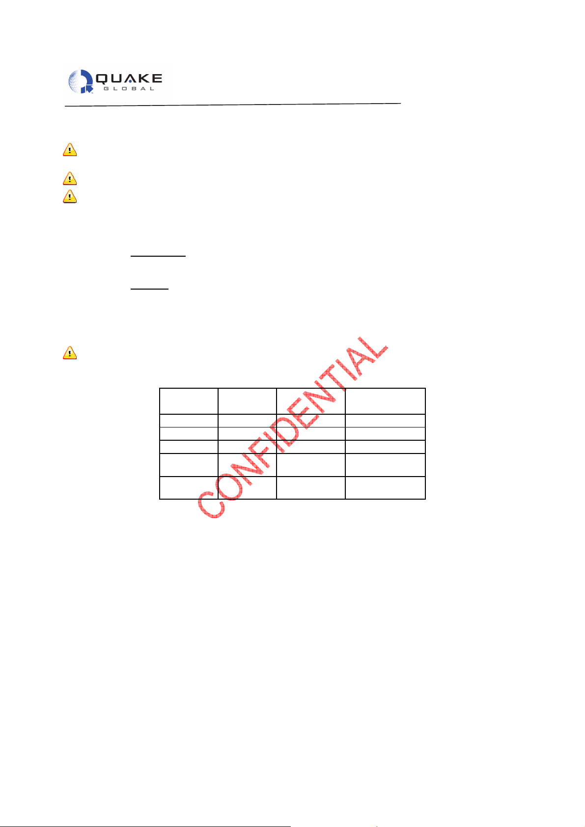
Table 3-1, Cable Loss Guidelines
Cable P/N Cable type Loss at 150
GHz dB/m
Belden 8216
Belden 9201
Belden 9913
TMS LMR
400
TMS LMR
600
RG-174 0.38 dB/m 1.59 dB/m
RG-58 0.181dB/m 0.792 dB/m
RG 8 0.56 dB/m 0.208 dB/m
LMR-400 0.54 dB/m 0.188 dB/m
LMR-600 0.034 dB/m 0.122 dB/m
Loss at 1600
GHz dB/m
ONFIDENTIAL
C
Document 1137-0901, REV A 11
Page 18
QPRO Technical Data Sheet
=
Information classified Confidential
-
Do not copy (See last page for obligations)
4 Customer Input/Output Interfaces (External)
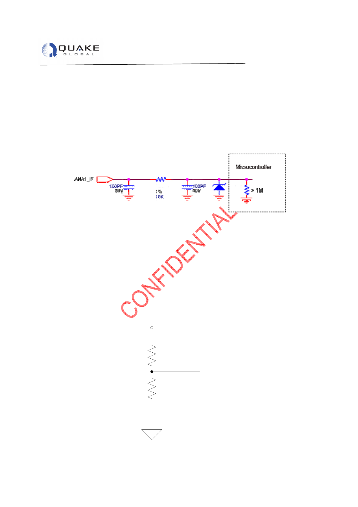
4.1 Analog Inputs
Two available: Pins 22 and 23
• 0 – 3.5 Volts.
• 12 bit resolution
• Greater than 1MΩ input impedance
• 3dB bandwidth and 160 kHz if driven with low impedance
Figure 4-1, Analog Input Circuit
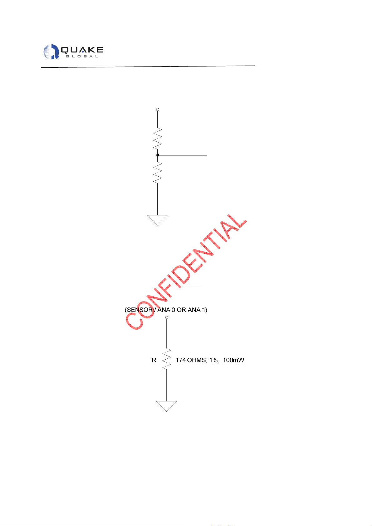
4.1.1 Sample Circuits for appropriate Scaling to 0-3.5V
Analog inputs are 12 bits and have a Full Scale (F
determine the resistor values for varying maximum sensor voltage readings
ONFIDENTIAL
C
F
s
=
12V = VFs
(SENSOR)
R1
3.5V
) reading of 4095. The equation below can be used to
scale
VoltageScaleFullV
( )
5.3
8.66K, 10mW
RR
+
21
R
2
ANA 0 OR ANA 1
.
R2
3.57K, 10mW
Document 1137-0901, REV A 12
Page 19
QPRO Technical Data Sheet
Information classified Confidential
-
Do not copy (See last page for obligations)
Figure 4-2, Sample 12V Sensor
24V
(SENSOR)
R1
3.5V
R2
Figure 4-3, Sample 24V Sensor
21K, 10mW
ANA 0 OR ANA 1
3.57K, 10mW
The equation below can be used to determine the appropriate resistor value for sensors that are current
scaled
.
=mAF
Full Scale Milliamp Reading
s
V
5.3
R
ONFIDENTIAL
C
The example below will scale a 0-20mA sensor to 0-3.5 VDC at the input to the modem
=
mAF
s
.
Figure 4-4, Sample 24V Sensor
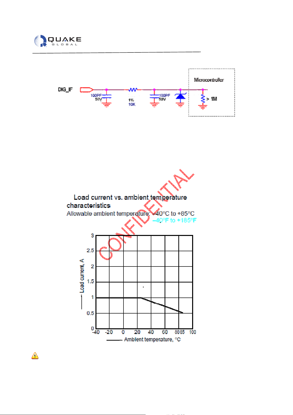
4.2 Digital Inputs/Outputs
Eight general purpose digital inputs/outputs are available: Pins 27 thru 34
• TTL/CMOS (3.5VDC) levels
• Configurable as inputs or outputs
• No internal pull-up or pull-down resistor
Document 1137-0901, REV A 13
Page 20
QPRO Technical Data Sheet
Figure 4-5, Digital Input Circuit
4.2.1 Switched Digital Relay
Four available: Pins 18/19 and 20/21
• Two pins route the supplied input voltage on Pins 18 and 19.
• Two pins provide switch closure to ground Pins 20 and 21.
These inputs can sink 1A continuous current at ambient temperatures and are de-rated as seen in the chart
below.
Figure 4-6, Switched Relay Characteristics
ONFIDENTIAL
C
Warning: Connecting SW_UBATT1 or SW_UBATT2 (pin 27 and 25) directly to ground while the switch
is turned “ON” will damage the unit. If SW_GND1 or SW_GND2 (pin 26 and 28) is tied directly to VBATT (Pin
Information classified Confidential - Do not copy (See last page for obligations)
Document 1137-0901, REV A 14
Page 21

QPRO Technical Data Sheet
1 and 2) while the switches are turned “ON,” the unit will be damaged
.
Inductive Load Use Warning: If an inductive load such as a relay is used, it can generate a spike
voltage across it. If that exceeds 60 volts peak the spike must be limited. Check if the external inductive load
is internally limited. If not, a clamp diode across the inductive load, with the cathode towards the positive
input lead must be used.
4.3 J1939
The J1939 bus connection is used on Heavy Trucks Engine Computers to obtain engine and other
subsystem parameters such as Oil Pressure and Fuel Level. See the SAE J1850/1939 specification for
additional information on this engine bus.
• CAN Bus with J1939 stack interface
• This bus is connected on pins 10 (CAN_H) and 11 (CAN_L)
4.4 3.5V Power
There are two pins that provide 3.5 VDC continuous power. One of the outputs can source up to 150 mA,
(Pin 4) and the other output can source up to 500 mA, (Pin 3). Don’t include these pins on the connector if
they are not being used. Connecting these pins incorrectly could damage the unit and void the warranty.
4.5 RS-232 Ports (General)
The QPRO has four (4) RS-232 serial ports. The first is the Main Transport Socket (MTS) Port, which
implements QUAKE’s Communication Protocol (QCP). The second is the Logger Port. The Logger Port
provides the diagnostic data for the user. The third and fourth serial ports are only available depending on
the specific QPRO model. See individual port descriptions for additional information. All serial ports support
baud rates up to 115.2 Kbps. All ports are protected against shorts to both the BATT+ and BATT- lines. The
serial ports meet the standard voltage level for RS-232 operation.
•
MTS Serial Port- The Main Transport Socket port; known as
port which implements the QUAKE Communications Protocol (QCP). For QPRO models that support
ONFIDENTIAL
C
ORBCOMM this port also supports the Orbcomm Serial Interface (OSI).
Pins: 13 (Tx), 14 (Rx), 15 (DSR), 16 (DTR), 17 (DCD), and GND (Pin 9, 12, 26, or
35)
• Logger Serial Port – RS-232 3-wire used for debugging and logging of system data/performance.
o Pins: 24 and 25. Rx and Tx respectively. GND (Pin 9, 12, 26, or 35).
• AUX Serial Port – RS-232 3-wire can be used by application developers on QPRO models that do
not include the Iridium satellite feature.
o Pins: 5 and 6. Tx and Rx respectively. GND (Pin 9, 12, 26, or 35)
• GSM Serial Port – RS-232 3-wire can be used on QPRO models which include the GSM feature for
firmware updates. For QPRO models that do not include the GSM feature this port can be used by
the application directly.
o Pins: 7 and 8. Tx and Rx respectively. GND (Pin 9, 12, 26, or 35).
Note: The auxiliary port is not available for customer use on QPRO models that include an Iridium or
Globalstar satellite option.
the MTS port, is an RS-232
Information classified Confidential - Do not copy (See last page for obligations)
4.6 Interface Connector Electrical Specification
Note: All lines are protected against over-voltage and transients (see Signal Description Section); the Max
(Min) Nominal Voltage column is intended to provide information about the voltage limits for normal
operation.
Document 1137-0901, REV A 15
Page 22

QPRO Technical Data Sheet
Pin Signal
Type
Voltage
Max Output
Notes
U
BATT (+)
UBATT (
-)
3V
5 OUT
Continuous Output
3V
5 OUT
Continuous Output
AUX_TX_RS232
AUX_
RX_RS232
GSM_R
X_RS232
G
SM_T
X_RS232
GND
CANH
CANL
GND
MTS_TXD_RS232
MTS_RXD_RS232
MTS_DSR_
RS232
MTS_DTR_RS232
MTS_DCD_RS232
SW_UBATT_0
SW_UBATT_1
SW_GND_0
21
SW_GND_1
Output
GND 1A@25C
1
ANA0
ANA1
LOG_TXD_RS232
LOG_RXD_RS232
GND
DIG_0
DIG_1
DIG_2
DIG_3
DIG_4
DIG_5
DIG_6
DIG_7
GND
Information classified Confidential
-
Do not copy (See last page for obligations)
Table 4-1, Interface Connector Electrical Specifications/RF Connections
(Min/Max/
Current
Nominal) VDC
1
2
3
4
5
6
7
8
9
10
11
12
13
14
15
16
17
18
19
20
22
23
24
25
ONFIDENTIAL
26
C
27
28
29
30
31
32
33
34
35
1. See
2. Asserted can wake the modem from sleep mode.
3. Input resistance high impedance >1M ohms
4. Pins 3 and 4 provide a continuous output that cannot be disabled. If any external voltages are applied to these
5. Pin 5 (AUX_TX_RS232) and Pin 6 (AUX_RX_RS232) are the DPL ports in the QPRO with Iridium version of the
6. If the QPRO contains an internal GPS, then Pin 12 (GPS_RX_RS232) is not connected. Otherwise it’s part of
Table 2-2,
pins it may cause permanent damage and will void the warranty. The combined current capacity of pins 3 and 4
cannot exceed 650 mAs.
modem.
the serial port.
, for complete operating current consumption specifications.
Power 5/36/12 See table 1
Ground
+/- 1% 650mA 4
+/- 1% 650mA 4
Output
Input
Input
Output +/- 15 -
Ground
Input/Output
Input/Output
Ground
Input
Output
Output
Input 5/36 2
Output
Output UBATT(+) 1A@25C 1
Output UBATT(+) 1A@25C 1
Output GND 1A@25C 1
Input 0-3.5 - 3
Input 0-3.5 - 3
Output
Input
Ground
Input/Output 3.5V CMOS/TTL 3
Input/Output 3.5V CMOS/TTL 3
Input/Output 3.5V CMOS/TTL 3
Input/Output 3.5V CMOS/TTL 3
Input/Output 3.5V CMOS/TTL 3
Input/Output 3.5V CMOS/TTL 3
Input/Output 3.5V CMOS/TTL 3
Input/Output 3.5V CMOS/TTL 3
Ground
Document 1137-0901, REV A 16
Page 23

QPRO Technical Data Sheet
2 MB
4 MB
8 MB
Information classified Confidential
-
Do not copy (See last page for obligations)
4.7 Customer Interface (Internal)
4.7.1 Memory
• 2 Mbytes standard of Flash and RAM.
• 4/8 Mbytes optional
The Q4000 can have 3 different memory configurations: 2MB, 4MB and 8 MB.
Table 4-2, User Flash and RAM Availability
Available Flash ~1 MB 2 MB 4 MB
Available RAM 0.5MB 2 MB 4 MB
A minimum of 100,000 raw program erase cycles are expected from the flash manufacturer before possible
failure. For Raw Flash, there are 64K Flash Sectors and each Flash File System Block is 512 Bytes. It is
recommended to write files that are 64K or larger to ensure that a whole Flash File System Block is written.
4.7.2 Real-Time Clock (RTC)
• Programmable
4.8 Environmental Considerations
The QPRO has been specifically designed for harsh environments. As an OEM product, it is housed in an IP67 rated enclosure.
• Operating Temperature
o –40C to 85C
ONFIDENTIAL
C
• Storage Temperature
o –50C to 85C.
• Low Pressure
o Up to 4 hours at 15000 ft elevation pressure
• Humidity
o Relative humidity range of 0% to 95% non-condensing at 65C
o Humidity Test in ORBCOMM Spec E25050102 REV D is per MIL SPEC 810E, Method 507.3
with test conditions.
Procedure I, Cycle 2
Procedure 1 simulates natural environmental cycles and it is conducted on test
items which are open to the environment of frequently ventilated, Cycle 2 set
temperature at 24 deg C constant with humidity maintained at 95% minimum. Test
Duration: 15 Cycles (15 days )
• Cyclic Humidity
o Temperature/Cyclic Humidity Test 5 days at -10C to 65C at 85% relative humidity
• Thermal Shock
o -40C to 85C (30 minutes at each temp, 10 cycles)
• Shock
o Mechanical shock of a 20G, saw tooth profile, over an 11 msec period. (Three positive and
three negative shocks in each of three mutually perpendicular axes)
o SAEJ1455 shock requirements and those in MIL-STD-810E [10].
Document 1137-0901, REV A 17
Page 24

QPRO Technical Data Sheet
Information classi
fied Confidential
-
Do not copy (See last page for obligations)
• Vibration
o 20 Hz to 2 KHz, 8 Grms vibration profile in each of three mutually perpendicular axes, 1 hour
per axis,
o 10 Hz to 150 HZ, 0.5 g square/Hz vibration profile in each of three mutually perpendicular
axes, 1 hour per axis.
o 10 Hz to 150 HZ, 0.05 g^2/Hz vibration, 16 hours on each of three orthogonal axis
o 5 Hz to 20 Hz , 0.05 g^2/hz, and from 20 to 150 Hz, -3 dB/octave, 1 hour each axes
o Vibration requirements in ORBCOMM Rev D spec [4] and MIL-STD-810E [10]
o SAEJ1455 vibration requirements.
ONFIDENTIAL
C
Document 1137-0901, REV A 18
Page 25

QPRO Technical Data Sheet
5 QPRO Data Interface Specifications
5.1 Data Interfaces
• 4 Digital Output Switches (2 Switched GND/2 Switched Input Power Voltage)
• 8 Digital General Purpose Inputs/Outputs (CMOS level 3.5VDC)
• 3 Serial Ports (External) Up to 4 RS-232’s depending on QPRO configuration
• 1 CAN BUS 2.0: J1850/1939
• 2 Analog Inputs (0 – 3.5 V)
Note: The auxiliary port is not available for customer use on QPRO models that include an Iridium satellite
option
5.2 Environmental Specifications & Certifications
• Operating Temperature: -40°C to +85°C
• Storage Temperature: -40°C to +85°C
5.3 Certifications
• ORBCOMM Type Approval pending
• Iridium Certification pending
• FCC
• CE
• J1455
• J1939 compliance
• IP67 out case
5.4 GSM/GPRS Module- Quad Band
PTCRB, FCC, CE, AT&T and T-Mobile Certifications Pending.
ONFIDENTIAL
C
5.5 Communications GSM
• Operating Temperature: -40°C ~ +85°C
• Band (Quad Dual Band)
• GSM850 (TX: 824.2~ 848.8 MHz/ RX: 869.2 ~ 893.8 MHz)
• EGSM900 (TX:890.0 ~ 914.8 MHz/Rx: 935.0 ~ 959.8 MHz)
(TX:880.2 ~ 889.8 MHz/Rx: 925.2 ~ 934.8 MHz)
• DCS-1800 (TX:1710.2 ~ 1784.8 MHz/Rx: 1805.2 ~ 1879.8 MHz)
• PCS-1900 (TX:1850.2 ~ 1909.8 MHz/Rx: 1930.2 ~ 1989.8 MHz)
• Transmit Output Power 2W (Class 4) for 850/900 bands
1W (Class 1) for 1800/1900 bands
5.6 Integrated GPS Chip Set
• 22 Channel Module
• Rapid-Time-To-First-Fix (TTFF) 38 seconds from a Cold Start.
• Accuracy within 2.5 meters
5.7 Application Interface
• ORBCOMM Serial Protocol
• QUAKE Application Programmer’s Interface API (C Code)
• Iridium Developers guide
• AT Command Set
Information classified Confidential - Do not copy (See last page for obligations)
Document 1137-0901, REV A 19
Page 26

QPRO Technical Data Sheet
5.8 Communications ORBCOMM
• Transmit Frequency: 148.000 to 150.050 MHz
• Receive Frequency: 137.000 to 138.000 MHz
• Transmit Power: 5W minimum 10W maximum
• Data Rates: 2400 bps Uplink 4800 bps Downlink
5.9 Communications Iridium
∙
Transmit Frequency: 1616 - 1626.5 MHz
∙
Receive Frequency: 1616 - 1626.5 MHz
∙
Transmit Power: 2W
∙
Data Rates: Up and Downlink: 50 ksps
5.10 Power
External Power Source: 6 – 32V* (*No ORBCOMM Tx from 6-10.5 VDC)
10.5 – 32V (All features supported)
Typical Power Consumption at 12V (not including other modem features):
∙
Transmit - ORBCOMM 22.26 Watts
∙
Transmit - GSM 7.80 Watts
∙
Transmit – Iridium 11.4 Watts
∙
Standby - ORBCOMM 11.4 Watts
∙
Standby - GSM 0.24 Watts
ONFIDENTIAL
∙
C
Standby – Iridium 1.02 Watts
∙
Sleep Mode 25µA (max)
∙
Note: The QPRO uses a switching mode DC-DC converter power supply. This means that the current draw
of the QPRO drops with an increase in the input voltage. QUAKE Global recommends that the QPRO be
connected to a power supply through a 5 Amp fast-blow fuse.
DC Input power to QUAKE QPRO modems is +6.0V to +32.0VDC. Input voltage outside this range will
result in damage to the modem and void the warranty.
5.11 Operation Modes
• Transmit: Communication with satellites or GSM network
• Standby: Continuous satellite reception or GSM network
• Monitoring: Processor on with radio’s off
• Sleep: Shut down. Waits for external input or scheduled start
Information classified Confidential - Do not copy (See last page for obligations)
5.12 Physical Specifications
Size: 4.69”x 3.65”x 2.27” (119.2mm x 92.7mm x 57.6mm)
Weight: 0.85 lbs (0.386Kg)
Document 1137-0901, REV A 20
Page 27

6 QPRO Drawings
Information classified Confidential
-
Do not copy (See last page for obligations)
QPRO Technical Data Sheet
ONFIDENTIAL
C
Figure 6-1, Dimensions for QPRO
Document 1137-0901, REV A 21
Page 28
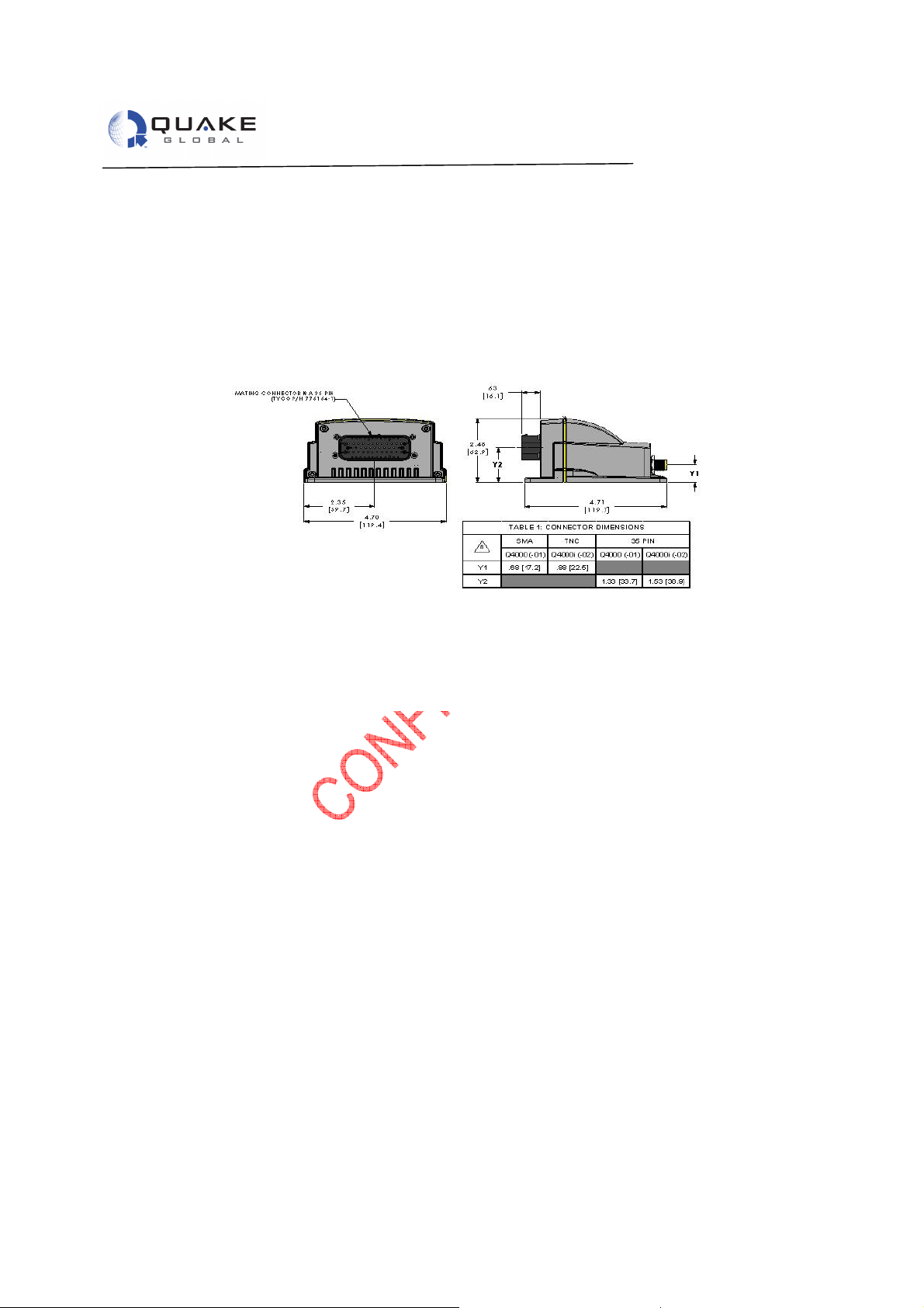
QPRO Technical Data Sheet
Information classified Confidential
-
Do not copy (See last page for obligations)
ONFIDENTIAL
C
Figure 6-2, Interface Connector for QPRO
Document 1137-0901, REV A 22
Page 29
QPRO Technical Data Sheet
Information classified Confidential
-
Do not copy (See last page for obligations)
ONFIDENTIAL
C
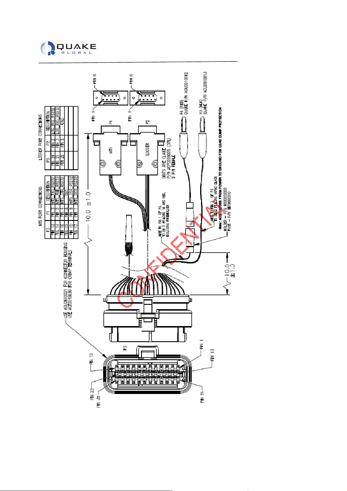
Figure 6-3, QPRO Development Kit Cable
Document 1137-0901, REV A 23
Page 30

QPRO Technical Data Sheet
7 QPRO Recommended Installation Guidelines
7.1 QPRO Mounting Recommendations
∙
Remember that it is best to connect the UBATT (-) to chassis ground rather than the (-) battery terminal.
∙
Remember that the input voltage range is 6-32 VDC.
∙
On the 40-pin connector positive power UBATT (+) is located on pins 1 and 2 and negative UBATT (-) is
Pins 3 and 4.
∙
In order to protect wires installed within the engine compartment or along the undercarriage make sure
all wires are wrapped with wire loom.
7.2 Antenna Recommendations
When selecting an Orbcomm antenna, make sure it is a 50 ohm 137-150.05 MHz antenna. Due to the fairly
wide frequency range used by Orbcomm (137 - 150 MHz), and the variety of installation factors and tradeoffs
between antenna size, cost, and performance, it is often not practical to achieve a VSWR of below 1.5:1
throughout the 137 - 150 MHz frequency range. See the User’s Guide User’s Guide to Q4000/QPRO,
Document #1135-4713 for more details on antennas.
Document 1137-0901, REV A 24
Page 31

QPRO Technical Data Sheet
Q: How do I contact service or a help desk?
Q: What type of PC do I need to program the QPRO?
Q: Can I use any ORBCOMM antenna
with the QPRO?
Q: Ca
n I use any GPS antenna with the QPEO?
Q: Does QUAKE provide any other products?
Q: How do I load firmware into the Q4000?
Q: Can I connect the QPRO directly to a vehicle power supply?
Q: The sensors I want to attach to my modem send out data as an ASCII string over a
8 Frequently Asked Questions
A: Email [email protected]
A: To configure the TurnKey application you can use any computer that runs a terminal
emulation program such as HyperTerminal, and at least one available serial port.
For users of QUAKE’s API any Windows computer can be used to set up the API and
Development Environment.
A: Yes. Any ORBCOMM antenna with 50-ohm impedance can be used with the QPRO.
However, there are great differences in the performance of various antennas and testing
ONFIDENTIAL
C
should occur to ensure proper operation for your application needs.
A: QUAKE recommends that the antenna shipped with the Development Kit be used with
the QPRO. This is a 3.3V active antenna with 26-dB gain. The QPRO can utilize a
passive or active 3.3VDC GPS antenna (Active recommended). Active antenna with 2050 dB gain @ 3.3 VDC. Max noise figure 1.5 dB. A 5V active antenna will not work with
the QPRO.
A: Yes. QUAKE offers a variety of products ranging from OEM modules to “Off the Shelf”
and ready to go turn-key products.
A: Loading new code is extremely easy with the use of the PC based QUAKE Configuration
Tool (QCT).
A: Yes. The QPRO is designed to work in most 12 and 24V based vehicles.
serial line. Will the QPRO accept this?
A: With the use of QUAKE’s Application Programmer’s Interface, the receiving serial data
can be received and used as needed.
Document 1137-0901, REV A 25
Information classified Confidential - Do not copy (See last page for obligations)
Page 32
QPRO Technical Data Sheet
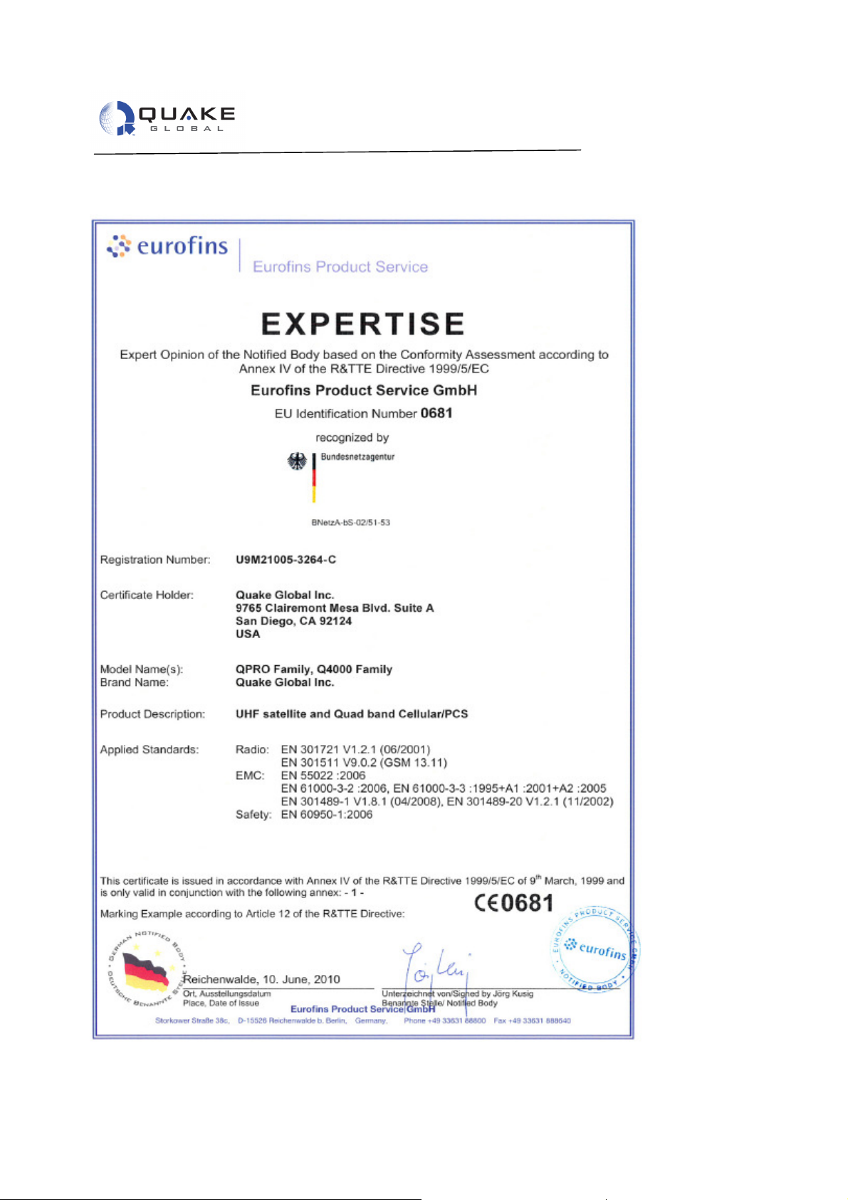
9 Declaration of Conformity
ONFIDENTIAL
C
Information classified Confidential - Do not copy (See last page for obligations)
Document 1137-0901, REV A 26
Page 33

QPRO Technical Data Sheet
Information classified Confi
dential
-
Do not copy (See last page for obligations)
PLEASE READ CAREFULLY:
CONFIDENTIALITY OBLIGATIONS
This document contains sensitive information and is classified “CONFIDENTIAL”.
Its distribution is subject to the recipient’s signature of a Non-Disclosure Agreement (NDA).
At all times you should comply with the following security rules (Refer to the NDA for detailed obligations):
This document may not be altered in any way that removes or obscures the Confidentiality notices.
Keep this document locked away.
Additional copies can be provided on a “need to know basis”, please contact your QUAKE account manager.
Please read carefully:
Information in this document is provided solely in connection with QUAKE Global, Inc. (“QUAKE”) products.
QUAKE reserves the right to make changes, corrections, modifications or improvements to this document
and the products and services described herein at any time, without notice.
All QUAKE products are sold pursuant to QUAKE’s terms and conditions of sale. Purchasers are solely
responsible for the choice, selection and use of QUAKE products and services described herein, and
QUAKE assumes no liability whatsoever relating to the choice, selection or use of QUAKE products and
services described herein. No license, express or implied, by estoppel or otherwise, to any intellectual
property rights is granted under this document. If any part of this document refers to any third party products
or services, it shall not be deemed a license grant by QUAKE for the use of such third party products or
services, or any intellectual property contained therein or considered as a warranty covering the use in any
manner whatsoever of such third party products or services or any intellectual property contained therein.
UNLESS OTHERWISE SET FORTH IN QUAKE’S TERMS AND CONDITIONS OF SALE, QUAKE
ONFIDENTIAL
DISCLAIMS ANY EXPRESS OR IMPLIED WARRANTY WITH RESPECT TO THE USE AND/OR SALE OF
C
QUAKE PRODUCTS INCLUDING, WITHOUT LIMITATION, IMPLIED WARRANTIES OF
MERCHANTABILITY, FITNESS FOR A PARTICULAR PURPOSE (AND THEIR EQUIVALENTS UNDER
THE LAWS OF ANY JURISDICTION), OR INFRINGEMENT OF ANY PATENT, COPYRIGHT OR OTHER
INTELLECTUAL PROPERTY RIGHT. UNLESS EXPRESSLY APPROVED IN WRITING BY AN
AUTHORIZED QUAKE REPRESENTATIVE, QUAKE PRODUCTS ARE NOT RECOMMENDED,
AUTHORIZED OR WARRANTED FOR USE IN MILITARY, AIRCRAFT, SPACE, LIFE SAVING, OR LIFE
SUSTAINING APPLICATIONS, NOR IN PRODUCTS OR SYSTEMS WHERE FAILURE OR
MALFUNCTION MAY RESULT IN PERSONAL INJURY, DEATH OR SEVERE PROPERTY OR
ENVIRONMENTAL DAMAGE.
Resale of QUAKE products with provisions different from the statements and/or technical features set forth in
this document shall immediately void any warranty granted by QUAKE for the QUAKE product or service
described herein and shall not create or extend in any manner whatsoever, any liability to QUAKE.
QUAKE and the QUAKE logo are trademarks or registered trademarks of QUAKE Global. Information in this
document supersedes and replaces all information previously supplied.
© 2010 QUAKE GLOBAL, INC. - All rights reserved
www.quakeglobal.com
Document 1137-0901, REV A 27
 Loading...