

Page 1
Document Number 4000-0900 Rev I
THIS DOCUMENT CONTAINS CONFIDENTIAL AND PROPRIETARY INFORMATION OF QUAKE GLOBAL CORPORATION. IT MAY BE USED BY RECIPIENT ONLY FOR
THE PURPOSE FOR WHICH IT WAS TRANSMITTED AND WILL BE RETURNED UPON REQUEST OR WHEN NO LONGER NEEDED BY RECIPIENT. DISCLOSURE TO
UNAUTHORIZED THIRD PARTIES OR DUPLICATION WITHOUT THE EXPRESS WRITTEN PERMISSION OF QUAKE GLOBAL IS PROHIBITED.
CONFIDENTIAL
Information classified Confidential
- Do not copy (See last page for obligations)
Features
• Iridium SBD
• GPS/GLONASS positioning
• Requires only one antenna
• Low power consumption
• Small form factor
• Global operating capability
• Incorporate into an OEM solution
• RoHS compliant
• SAE J1455
Applications
• Fixed and moving asset tracking /
monitoring
• Heavy equipment
Product description
The QUAKE QLOCATETM is an Iridium Short
Burst Data (SBD) transceiver available in two
standard configurations: one is a simple SBD
transceiver, and the other one is also integrated
with a GPS/GLONASS receiver. It is an
efficient, satellite add-on solution that allows
effortless connection to Iridium’s satellite
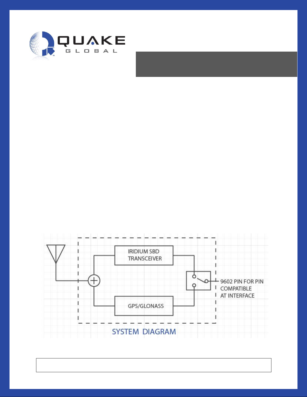
network. The QLOCATE can switch smoothly
between satellite and GPS mode.
A unique option of the QLOCATE is its built-in,
state-of-the-art GPS/GLONASS receiver that
allows system integrators to use a single,
dual-mode, L-Band antenna for both
GPS/GLONASS and Iridium SBD. This
eliminates the need for a second antenna and
for external global positioning modules.
The QLOCATE’s simple installation and
integration make it optimal for any developer
who is facing an accelerated time-to-market
requirement.
Document number 1158-0901, Rev E
QLOCATE Technical Data Sheet
SENSITIVITY LEVEL: YELLOW
This document contains confidential and proprietary information of Quake Global corporation. It may be used by recipient only for the purpose for which it was transmitted
and will be returned upon request or when no longer needed by recipient. Disclosure to unauthorized third parties or duplication without the express written permission of
Quake Global is prohibited. ©2018 QUAKE GLOBAL, INC. - All rights reserved
Page 2
Technical Data Sheet
QLOCATE
Document Number 1158-0901 Rev E
This document contains confidential and proprietary information of Quake Global corporation. It may be used by recipient only for the purpose for which it was transmitted and
will be returned upon request or when no longer needed by recipient. Disclosure to unauthorized third parties or duplication without the express written permission of Quake
Global is prohibited. © 2018 QUAKE GLOBAL, INC. - All rights reserved.
CONFIDENTIAL
Information classified
Confidential
- Do not copy (See last page for obligations)
Page i
Revision History
Date
Rev
ECO
Description
Jun 2014
X1
1187
Preliminary release of the Technical Data Sheet.
Jul 2014
X2
1212
Second preliminary release of the Technical Data Sheet.
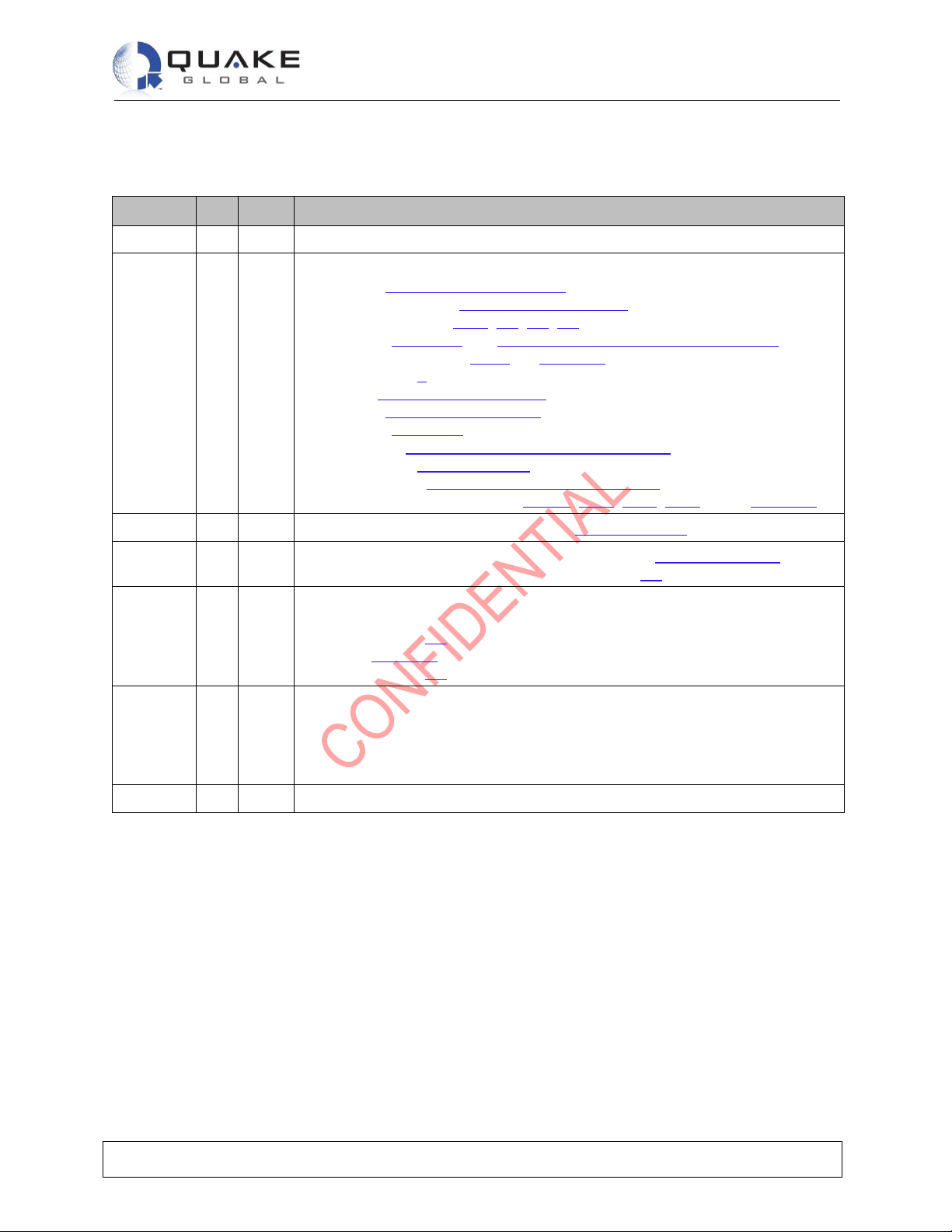
• In section 3 - Input/Output interfaces:
- Modified section 3.1 - Interface connector
- Added sections 3.1.1, 3.2, 3.3, 3.4
- Added Figure 3-1 and Figure 3-2: Typical supply current profile
- Enhanced section 3.1.3 and Table 3-3
• Added section 4
• Updated Table 5-2: Certifications
• In section 6 - Technical drawings:
- Added Figure 6-1
- Updated Figure 6-2: QLOCATE dimensions (2)
• Added section 7.1.1 - Mounting
• Modified section 8 - AT Command Set Description
• Modified pin 5 info in sections 2.1.2.1, 2.1.3, 7.2.1, 7.2.2 and in Table 3-1
Nov 2014
A
1341
• Added hot surface warning to section 7.1.1 - Mounting
Mar 2015
B
1425
• Updated the FCC, IC and CE numbers in section 5.2 - Certifications.
• Added the Declaration of Conformity to section 5.3.
May 2015
C
1526
• Updated for non-GPS/GLONASS option in:
- cover page
- section 2.1
- Table 3-1
- section 7.2
Feb 2018
D
2213
• Updated document with new company address
• Fixed pinout issue (Drawing)
• Edited the Declaration of Conformity on CE section
• Revised specs for GPS on 9602N
• Updated firmware update instructions
Oct 2018
E
• Updated FCC ID in needed sections
Page 3

Technical Data Sheet
QLOCATE
Document Number 1158-0901 Rev E
This document contains confidential and proprietary information of Quake Global corporation. It may be used by recipient only for the purpose for which it was transmitted and
will be returned upon request or when no longer needed by recipient. Disclosure to unauthorized third parties or duplication without the express written permission of Quake
Global is prohibited. © 2018 QUAKE GLOBAL, INC. - All rights reserved.
CONFIDENTIAL
Information classified
Confidential
- Do not copy (See last page for obligations)
Page ii
Table of Contents
1 INTRODUCTION ....................................................................................................... 1
Scope ............................................................................................................................. 1
Iridium ............................................................................................................................ 1
Short Burst Data (SBD) .................................................................................................. 1
Related documents ........................................................................................................ 2
Evaluation Kits ............................................................................................................... 2
Contacting QUAKE ........................................................................................................ 2
2 COMMUNICATIONS ................................................................................................. 3
2.1 Operating modes ............................................................................................................ 4
2.1.1 Power OFF .............................................................................................................................. 4
2.1.2 Power ON ................................................................................................................................ 4
2.1.2.1 RF Receive/Idle ................................ .................................................................................................. 4
2.1.2.2 Transmit ............................................................................................................................................. 4
2.1.3 Switch from Iridium to GPS/GLONASS ................................................................................... 4
3 INPUT/OUTPUT INTERFACES ................................................................................ 5
3.1 Interface connector ........................................................................................................ 5
3.1.1 Type ......................................................................................................................................... 5
3.1.2 Electrical specifications ........................................................................................................... 5
3.1.3 Power consumption ................................................................................................................. 7
3.2 Serial data interface ................................................................ ....................................... 9
3.3 Network Available output ................................................................................................ 9
3.4 DC supply indicator output ............................................................................................. 9
4 RF INTERFACE ................................................................ ................................ ...... 10
4.1 Connector types ........................................................................................................... 10
4.2 ANT connector ............................................................................................................. 10
4.2.1 Antenna characteristics ......................................................................................................... 10
4.3 RF interface specifications ........................................................................................... 11
4.4 Radio characteristics .................................................................................................... 11
5 RATINGS AND CERTIFICATIONS ........................................................................ 12
5.1 Ratings ......................................................................................................................... 12
5.2 Certifications ................................................................................................................ 13
5.3 Declaration of Conformity ............................................................................................. 16
6 TECHNICAL DRAWINGS ....................................................................................... 17
7 OPERATION ........................................................................................................... 19
7.1 Installation recommendations ....................................................................................... 19
7.1.1 Mounting ................................................................................................................................ 19
7.2 Basic operation ............................................................................................................ 20
7.2.1 Iridium satellite....................................................................................................................... 20
7.2.2 GPS option ............................................................................................................................ 20
8 AT COMMAND SET DESCRIPTION ...................................................................... 23
Page 4

Technical Data Sheet
QLOCATE
Document Number 1158-0901 Rev E
This document contains confidential and proprietary information of Quake Global corporation. It may be used by recipient only for the purpose for which it was transmitted and
will be returned upon request or when no longer needed by recipient. Disclosure to unauthorized third parties or duplication without the express written permission of Quake
Global is prohibited. © 2018 QUAKE GLOBAL, INC. - All rights reserved.
CONFIDENTIAL
Information classified
Confidential
- Do not copy (See last page for obligations)
Page iii
8.1 Example: Send and receive a message ....................................................................... 23
9 MODEM SOFTWARE UPDATE ............................................................................. 24
10 APPENDIX A – GLOSSARY OF TERMS ............................................................... 25
List of Figures
Figure 3-1: Interface connector pin number designation (from below module) ........................................... 7
Figure 3-2: Typical supply current profile ..................................................................................................... 8
Figure 6-1: QLOCATE dimensions (1) ....................................................................................................... 17
Figure 6-2: QLOCATE dimensions (2) ....................................................................................................... 17
Figure 6-3: QLOCATE ................................................................................................................................ 18
Figure 7-1: QLOCATE mounting example ................................................................................................. 19
Figure 7-2: NMEA message structure (1) .................................................................................................. 21
Figure 7-3: NMEA message structure (2) .................................................................................................. 22
List of Tables
Table 2-1: Communication networks ........................................................................................................... 3
Table 3-1: Interface connector pin allocation ............................................................................................... 5
Table 3-2: Limits for 3.3V digital signals ...................................................................................................... 6
Table 3-3: Current draw (5 VDC) ................................................................................................................. 7
Table 4-1: Antenna characteristics ............................................................................................................ 10
Table 4-2: General RF parameters ............................................................................................................ 11
Table 4-3: Radio characteristics ................................................................................................................ 11
Table 5-1: Environmental ratings ............................................................................................................... 12
Table 5-2: Certifications ............................................................................................................................. 13
Table 6-1: QLOCATE dimensions ............................................................................................................. 18
Table 6-2: QLOCATE part numbers ............................................................ Error! Bookmark not defined.
Page 5

Technical Data Sheet
QLOCATE
Document Number 1158-0901 Rev E
This document contains confidential and proprietary information of Quake Global corporation. It may be used by recipient only for the purpose for which it was transmitted and
will be returned upon request or when no longer needed by recipient. Disclosure to unauthorized third parties or duplication without the express written permission of Quake
Global is prohibited. © 2018 QUAKE GLOBAL, INC. - All rights reserved.
CONFIDENTIAL
Information classified
Confidential
- Do not copy (See last page for obligations)
Page 1
0-byte messages are referred to as “mailbox checks.”
The information in this document is subject to change.
1 Introduction
Scope
This data sheet contains a description of the operation, specifications and characteristics of the QUAKETM
QLOCATE, which is an Iridium Short Burst Data (SBD) transceiver integrated with GPS/GLONASS.
Iridium
Iridium’s network is a global satellite data solution, with complete coverage of the earth (including
continental, ocean, and Polar Regions). Iridium delivers low latency, essential communications services
to and from remote areas where no other form of communication is available. The Iridium constellation of
66 low-earth orbiting (LEO) satellites operates as a fully meshed network. It is one of the largest
commercial satellite constellations in the world. The Iridium service is ideally suited for industries such as
maritime, aviation, government, emergency/humanitarian services, mining, forestry, oil and gas, heavy
equipment, transportation and utilities.
Short Burst Data (SBD)
Iridium Short Burst Data (SBD) Service is an efficient network protocol designed for shorter-sized data
messages that can be economically sent via Iridium Circuit Switched Data Services. SBD uses a
proprietary network protocol to transfer data messages to and from the remote terminal. Currently, the
QLOCATE supports only Iridium’s SBD service.
It is possible to send Mobile Originated (MO-SBD) and Mobile Terminated (MT-SBD) messages.
Message sizes for:
• MO-SBD are between 0 and 340 bytes;
• MT-SBD are between 1 and 270 bytes.
Note:
Note:
Page 6

Technical Data Sheet
QLOCATE
Document Number 1158-0901 Rev E
This document contains confidential and proprietary information of Quake Global corporation. It may be used by recipient only for the purpose for which it was transmitted and
will be returned upon request or when no longer needed by recipient. Disclosure to unauthorized third parties or duplication without the express written permission of Quake
Global is prohibited. © 2018 QUAKE GLOBAL, INC. - All rights reserved.
CONFIDENTIAL
Information classified
Confidential
- Do not copy (See last page for obligations)
Page 2
Related documents
QUAKE
QUAKE documentation can be obtained by contacting QUAKE Customer Support.
Iridium
The following Iridium documentation may be helpful:
[1] Iridium SBD Developer’s Guide (QUAKE P/N: 4000-0713)
[2] Iridium ISU AT Command Set (QUAKE P/N: REF-IRI-001)
Evaluation Kits
QLOCATE Evaluation Kits are available from QUAKE. They include: the QLOCATE modem, the data
cable, all documentation, and air time. Contact your QUAKE sales representative for more details.
Contacting QUAKE
Quake Global, Inc.
4711 Viewridge Ave. Suite 150
San Diego, CA 92123
Phone: (858)-277-7290
Fax: (858) 277-7259
Website: www.quakeglobal.com
Submit a Customer Support Ticket: http://www.quakeglobal.com/support
Email: [email protected]
Page 7

Technical Data Sheet
QLOCATE
Document Number 1158-0901 Rev E
This document contains confidential and proprietary information of Quake Global corporation. It may be used by recipient only for the purpose for which it was transmitted and
will be returned upon request or when no longer needed by recipient. Disclosure to unauthorized third parties or duplication without the express written permission of Quake
Global is prohibited. © 2018 QUAKE GLOBAL, INC. - All rights reserved.
CONFIDENTIAL
Information classified
Confidential
- Do not copy (See last page for obligations)
Page 3
2 Communications
Table 2-1: Communication networks
Communication Network
Parameter
Units
Comments
Iridium Short Burst Data (IRI SBD)
Message Size
Modem Originated (TX)
1 / 340
Bytes MIN / MAX
Modem Terminated (RX)
270
Bytes MAX
Transmit
Frequency
1616 / 1626.5
MHz MIN / MAX
Power
32
dBm Typical
Receive
Frequency
1616 / 1626.5
MHz MIN / MAX
Sensitivity
-113
dBm
1X10⁻² BER
GPS Satellite channels
72
channels
Time-To-First-Fix (TTFF)
Depending on antenna and signal strength.
From cold start
26
seconds
Unobstructed view of the sky.
Sensitivity
Tracking
-167
dBm Acquisition
-148
dBm Accuracy
2
meters
Raw location data update (NMEA)
1
second
GLONASS
Satellite channels
72
channels
Time-To-First-Fix (TTFF)
Depending on antenna and signal strength.
All satellites at -130 dBm
From cold start
26
seconds
Unobstructed view of the sky.
Sensitivity
Demonstrated with good external LNA.
Tracking
-167
dBm Acquisition
-148
dBm Accuracy
2
meters
Raw location data update (NMEA)
1
seconds
Antenna
Satellite/GPS
Gain
Cable loss
50
3
3
Ohms
dBm
dBm MAX
These specifications reflect QLOCATE’s design for
use with a passive antenna.
• Iridium specifies an antenna with 3dBi Gain,
RHCP polarization, 50 Ω nominal impedance
and 1.5:1 VSWR. Several vendors have patch
antennas that will meet this specification, and
are certified by Iridium to operate on their
network.
• If the user’s design requires use of an active
antenna for the GPS, the design of their
application will require additional circuitry.
Page 8

Technical Data Sheet
QLOCATE
Document Number 1158-0901 Rev E
This document contains confidential and proprietary information of Quake Global corporation. It may be used by recipient only for the purpose for which it was transmitted and
will be returned upon request or when no longer needed by recipient. Disclosure to unauthorized third parties or duplication without the express written permission of Quake
Global is prohibited. © 2018 QUAKE GLOBAL, INC. - All rights reserved.
CONFIDENTIAL
Information classified
Confidential
- Do not copy (See last page for obligations)
Page 4
2.1 Operating modes
2.1.1 Power OFF
• The QLOCATE with GPS/GLONASS is no longer functional when external power is removed.
• The QLOCATE without GPS/GLONASS can be controlled by the ON/OFF pin (5) when external
power is applied. The modem is no longer functional when external power is removed.
2.1.2 Power ON
• The QLOCATE with GPS/GLONASS is ON when input voltage to the modem is applied.
• For QLOCATEs without GPS/GLONASS, the ON/OFF signal must be asserted when power is
applied in order to turn on the modem.
2.1.2.1 RF Receive/Idle
The QLOCATE alternates between the idle state and receiving receive bursts.
In Receive mode:
The RF and digital signal processor portions of the modem are active, and GPS is not active.
In Idle mode:
The required input power along with the assertion of the ON/OFF signal (pin 5) must not be present; GPS
will be active.
2.1.2.2 Transmit
The QLOCATE is sending an outgoing SBD message. The QLOCATE may also query the Iridium system
in a search for incoming messages (see AT Command Set manual for sequence and commands and
section 8 - AT Command Set Description).
2.1.3 Switch from Iridium to GPS/GLONASS
For QLOCATEs with GPS/GLONASS:
The QLOCATE alternates between Iridium and GPS/GLONASS. To enter GPS/GLONASS mode, the
required input power along with the ON/OFF signal (pin 5) must be low. The NMEA data will
subsequently be sent to the Rx port.
Page 9

Technical Data Sheet
QLOCATE
Document Number 1158-0901 Rev E
This document contains confidential and proprietary information of Quake Global corporation. It may be used by recipient only for the purpose for which it was transmitted and
will be returned upon request or when no longer needed by recipient. Disclosure to unauthorized third parties or duplication without the express written permission of Quake
Global is prohibited. © 2018 QUAKE GLOBAL, INC. - All rights reserved.
CONFIDENTIAL
Information classified
Confidential
- Do not copy (See last page for obligations)
Page 5
Ensure that all power pins and ground pins are connected externally.
3 Input/Output interfaces
3.1 Interface connector
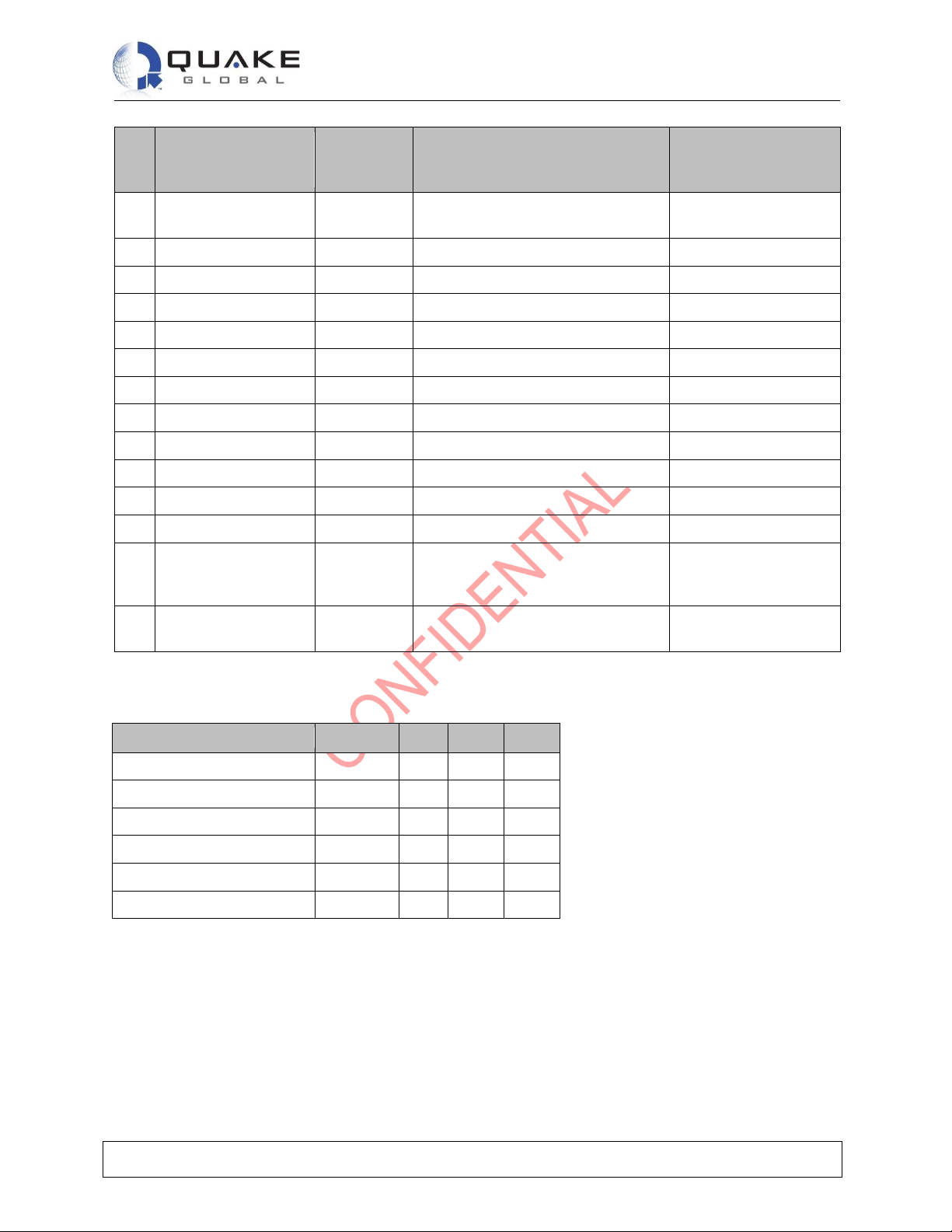
The QLOCATE has a 20 pin interface connector. The pinout is shown in Table 3-1 and the limits for the
digital signals are listed in Table 3-2. The connector contains several supply grounds; all supply and
supply grounds must be connected to the power supply to ensure that the current on any one pin is
limited. Cross-talk is reduced through the use of multiple signal grounds.
The interface connector provides the following connections to the QLOCATE:
• DC power supply input
• Power on/off control
• Serial data interface
• Network available output
• Supply power indicator output
3.1.1 Type
The connector on the QLOCATE is a Samtec low-profile header connector, part number FTSH-110-01-LDV. This connector makes a stackable board-to-board configuration possible, enabling connection to the
host system motherboard. A suitable motherboard female socket that matches this connector is the
SAMTEC header, part number CLP-110-02-L-D. See the Samtec website at: http://www.samtec.com for
more information on this connector.
3.1.2 Electrical specifications
Table 3-1: Interface connector pin allocation
Pin
Signal Name
Sig Dir
(WRT the
QLOCATE)
Signal Function
Signal Level
1
EXT_PWR
Input
Supply
+5V ±0.5V
2
EXT_PWR
Input
Supply
+5V ±0.5V
3
EXT_GND
Input
Supply return
0V 4 EXT_GND
Input
Supply return
0V
5
ON/OFF
Input
With GPS/GLONASS
On/Off control input
(On=IRI, Off= GPS)
Without GPS/GLONASS
On/Off control input turns
QLOCATE On/Off
Analog
On: ≥2.0V Off: ≤0.5V
6
DF_S_TX (pin 5=On)
GPS_TX (pin 5=Off)
Input
Data port, serial data input
3.3V Digital
Note:
Page 10
Technical Data Sheet
QLOCATE
Document Number 1158-0901 Rev E
This document contains confidential and proprietary information of Quake Global corporation. It may be used by recipient only for the purpose for which it was transmitted and
will be returned upon request or when no longer needed by recipient. Disclosure to unauthorized third parties or duplication without the express written permission of Quake
Global is prohibited. © 2018 QUAKE GLOBAL, INC. - All rights reserved.
CONFIDENTIAL
Information classified
Confidential
- Do not copy (See last page for obligations)
Page 6
Pin
Signal Name
Sig Dir
(WRT the
QLOCATE)
Signal Function
Signal Level
7
DF_S_RX (pin 5=On)
GPS_RX (pin 5=Off)
Output
Data port, serial data output
3.3V Digital
8
SIG_GND
Input
Signal ground
0V 9 DF_DCD
Output
Data port, Data Carrier Detect
3.3V Digital
10
DF_DSR
Output
Data port, Data Set Ready
3.3V Digital
11
DF_CTS
Output
Data port, Clear-to-Send
3.3V Digital
12
DF_RI
Output
Data port, Ring Indicator
3.3V Digital
13
DF_RTS
Input
Data port, Request-to-Send
3.3V Digital
14
DF_DTR
Input
Data port, Data Terminal Ready
3.3V Digital
15
SIG_GND
Input
Signal ground
0V
16
Reserved
17
Reserved
18
SIG_GND
Input
Signal ground
0V
19
NETWORK
AVAILABLE
Output
Signals when the QLOCATE can
see an available satellite network
3.3V Digital
Available = high
Not available= low
20
SUPPLY_OUT
Output
Supply power indicator output
+3.3V
5mA maximum
Table 3-2: Limits for 3.3V digital signals
Parameter
Symbol
Min
Max
Unit
Input High Voltage
VIH
2.0
5.5
V
Input Low Voltage
VIL
-0.3
0.8
V
Output High Voltage
VOH
2.4 V
Output Low Voltage
VOL
0.4
V
Low Level Output Current
IOL
4.4
mA
High Level Output Current
IOH
5.5
mA
Page 11
Technical Data Sheet
QLOCATE
Document Number 1158-0901 Rev E
This document contains confidential and proprietary information of Quake Global corporation. It may be used by recipient only for the purpose for which it was transmitted and
will be returned upon request or when no longer needed by recipient. Disclosure to unauthorized third parties or duplication without the express written permission of Quake
Global is prohibited. © 2018 QUAKE GLOBAL, INC. - All rights reserved.
CONFIDENTIAL
Information classified
Confidential
- Do not copy (See last page for obligations)
Page 7
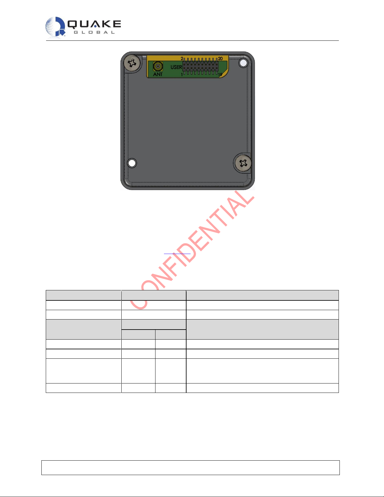
Figure 3-1: Interface connector pin number designation (from below module)
3.1.3 Power consumption
Power consumption is dependent on the mode in which the QLOCATE is operating. The amount of time
the QLOCATE spends in any of its modes will determine the overall current draw.
The current draw specifications detailed in Table 3-3 apply to DC power measured at the QLOCATE’s
interface connector input and not at the output of the power supply. If the power supply cables are
excessively long a voltage drop can occur that is sufficient to cause the voltage to be out of specification
at the physical power supply input to the QLOCATE.
Table 3-3: Current draw (5 VDC)
Supply Input Voltage
Value
Notes
Range
5.0 DC ± 0.5V
Ripple
< 40 mV pp
Mode
Current Draw
Average
Peak
Receive/Idle
45 mA
195 mA
Transmit
190 mA
1.5 A
SBD message transfer
• current
• power
190 mA
≤ 1.0 W
The average current draw will vary depending on the
view of the satellite from the antenna.
GPS/GLONASS
45 mA
High current drive is required during transmissions.
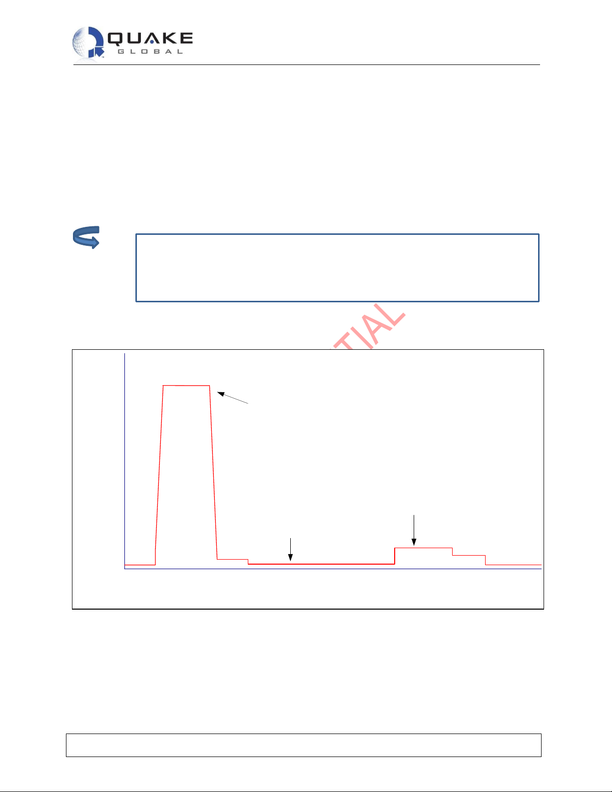
• The typical transmit burst is 8.3 ms (and repeats every 90 ms).
• The typical receive burst is up to 4.5 seconds.
Page 12
Technical Data Sheet
QLOCATE
Document Number 1158-0901 Rev E
This document contains confidential and proprietary information of Quake Global corporation. It may be used by recipient only for the purpose for which it was transmitted and
will be returned upon request or when no longer needed by recipient. Disclosure to unauthorized third parties or duplication without the express written permission of Quake
Global is prohibited. © 2018 QUAKE GLOBAL, INC. - All rights reserved.
CONFIDENTIAL
Information classified
Confidential
- Do not copy (See last page for obligations)
Page 8
In-rush limit refers to the impedance of the modem, which is very low when it is
unpowered. When power is supplied from an unlimited supply, the instantaneous
current can exceed 4 Amps which can cause damage to the modem. This can be
limited in several ways, included using a supply that cannot provide more than 4 Amps
instantaneously; or providing some series inductance/resistance to the supply lead.
The following must be guaranteed by the external power supply:
• The supply voltage droop over for a 8.3ms burst of 1.5A current should not be more than 0.2 V.
• The in-rush current should be limited to a maximum of 4 Amps
• The power source shall provide for over current protection in case of device malfunction.
• The supply noise should be less than the limits in the following profile:
• 100 mVpp from 0 to 50 kHz
• 5 mVpp at 1 MHz measured in 50 kHz bandwidth
• 10 mVpp at 1 MHz measured in 1MHz bandwidth
• 5 mVpp above 5 MHz measured in 1 MHz bandwidth.
Supply Current (A)
Time (mS)
1.6
1.5
1.4
1.3
1.2
1.1
1.0
0.9
0.8
0.7
0.6
0.5
0.4
0.3
.02
0.1
0
-10 0 10 20 30 40 50 60 70
Transmitter data burst
(typically 1.5A)
Background
(typically 40mA)
Receiver data burst
(typically 195mA)
Figure 3-2: Typical supply current profile
Note:
Page 13

Technical Data Sheet
QLOCATE
Document Number 1158-0901 Rev E
This document contains confidential and proprietary information of Quake Global corporation. It may be used by recipient only for the purpose for which it was transmitted and
will be returned upon request or when no longer needed by recipient. Disclosure to unauthorized third parties or duplication without the express written permission of Quake
Global is prohibited. © 2018 QUAKE GLOBAL, INC. - All rights reserved.
CONFIDENTIAL
Information classified
Confidential
- Do not copy (See last page for obligations)
Page 9
The behavior of +CIEV:1 is identical to that of the Network Available output.
3.2 Serial data interface
The serial data interface is an RS-232 9-wire interface at 3.3V digital signal levels (LVTTL) over which the
QLOCATE and the customer solution transfer commands, responses, and SBD message data. In using
this interface, the QLOCATE behaves as a DCE (Data Communication Equipment), and the customer
solution behaves as a DTE (Data Terminal Equipment).
• If RS-232 voltage levels are needed, the customer solution must include an LVTTL/RS-232
level-shifter.
• Autobaud is not supported. The baud rate can be set via the AT+IPR command. The default
rate is 19200 bps.
The QLOCATE’s serial interface supports the control signaling of a 9-wire interface by default for those
host applications that require it. However, the interface can also be configured for 3-wire operation – in
which only transmit, receive and ground signals are used – with no detriment to functionality/performance.
See the ISU AT Command Set for more information.
3.3 Network Available output
Network Available is a digital output that can notify an application that the QLOCATE has visibility to the
Iridium satellite network. This feature is helpful when the movement of the QLOCATE reduces the
amount of time that it has a clear line of sight to the satellite. If the customer solution includes this logic
output in the application decision logic, battery life can be preserved by thereby reducing the number of
attempted transmissions.
Network Available means only that the QLOCATE can successfully receive the Ring Channel (namely, it
has an Iridium satellite in view). It is not a guarantee that a message can be successfully sent. The
Network Available state is evaluated every time the Ring Channel is received, which is typically every 4
seconds if the Ring Channel is visible. If the Ring Channel is not currently visible, the update time can
take as long as 2 minutes, depending on how long the lack of satellite visibility existed. The update time
varies because the QLOCATE attempts to conserve power by increasing the Ring Channel search
interval as long as the satellites are not in view. Every time a ring search fails, the time to wait is
increased and eventually limits at 120 seconds.
If Network Available is currently off, the customer solution may still attempt an SBDI[X] session. This will
force the QLOCATE to look for the Ring Channel immediately and, upon finding it, to attempt to send the
message. In this case, Network Available will not come on immediately. The Network Available does not
turn on while in a +SBDI session. It will, however, turn on 4 seconds later due to the assumption that the
Ring Channel is present. After the SBD session completes, the QLOCATE performs a new Ring Channel
search, at the end of which Network Available is turned on. This can take between 4 and 12 seconds.
The wait time between search windows is reset to 4 seconds every time a search succeeds. Otherwise, it
continues to increase. Therefore, if the +SBDI attempt fails to find the Ring Channel, the search window
does not reset to 4 seconds.
3.4 DC supply indicator output
A DC supply indicator signal is provided which could be used directly for driving an LED to provide a
visible indication that the QLOCATE’s supply is on. Alternatively, the output signal could be used in
application logic to determine whether the internal transceiver power supply is on.
Note:
Page 14
Technical Data Sheet
QLOCATE
Document Number 1158-0901 Rev E
This document contains confidential and proprietary information of Quake Global corporation. It may be used by recipient only for the purpose for which it was transmitted and
will be returned upon request or when no longer needed by recipient. Disclosure to unauthorized third parties or duplication without the express written permission of Quake
Global is prohibited. © 2018 QUAKE GLOBAL, INC. - All rights reserved.
CONFIDENTIAL
Information classified
Confidential
- Do not copy (See last page for obligations)
Page 10
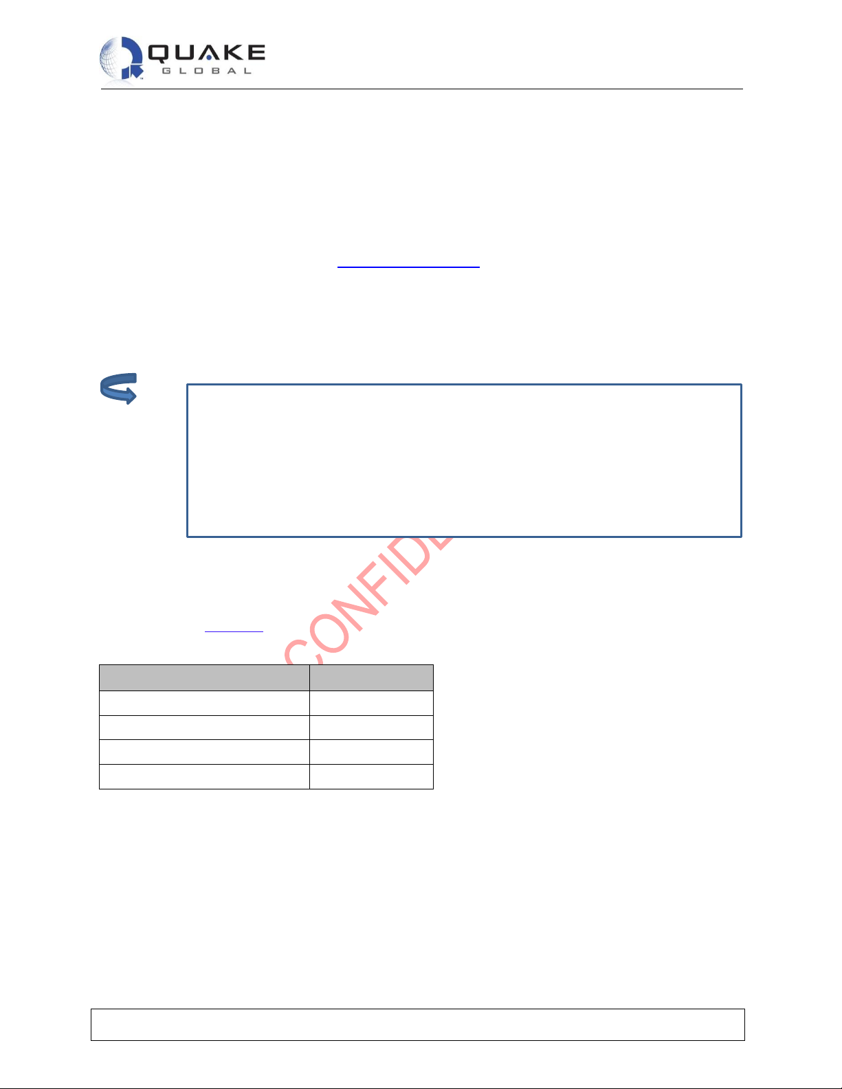
For safety reasons, the RF connector on the QLOCATE is intended for an inter-board
connection to the host system motherboard and should not be directly connected to an
external antenna cable or cable distribution system. Paragraph 7.3 of EN60950-1:2006
safety standard requires that users are protected against high voltages that might
appear on these cables. This can be achieved either by inserting a high-voltage
isolating capacitor in series with the signal or by grounding the shield of the coaxial
cable. The MMCX connectors have limited voltage capacity; therefore, protection
needs to be provided on the developer’s motherboard. Developers are encouraged to
review the EN60950-1:2006 standard for additional details.
4 RF interface
4.1 Connector types
When mating to the QLOCATE RF connector, use MMCX male connectors from SAMTEC, part number
MMCXP-P-H-ST-TH1. This is a thru hole printed circuit mount connector with the correct mechanical
spacing to allow the QLOCATE to fit flush on the motherboard.
Additional information can be found at: http://www.samtec.com.
4.2 ANT connector
The main RF connector for the QLOCATE is the antenna connector. This provides the RF connection
between the QLOCATE and the host system motherboard.
4.2.1 Antenna characteristics
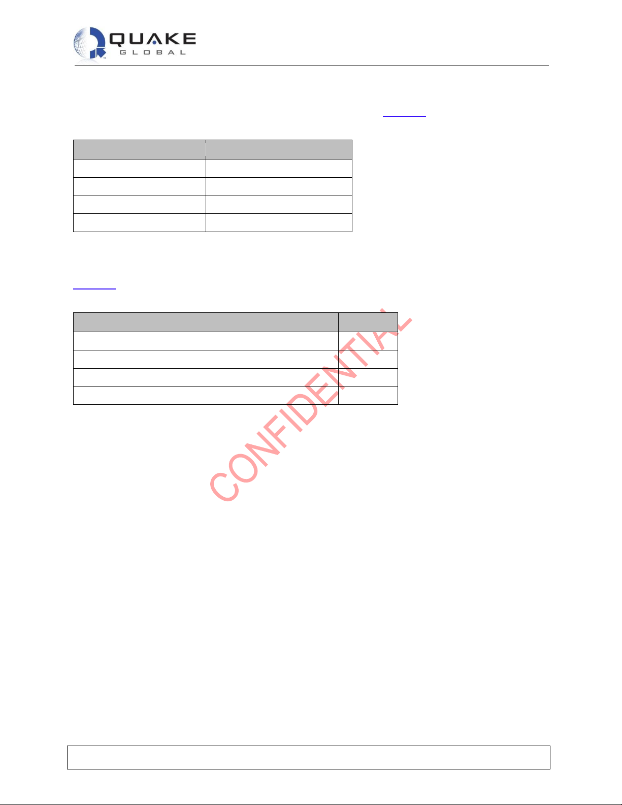
The QLOCATE should be connected to an Iridium-band antenna with the following antenna connector
characteristics in Table 4-1.
Table 4-1: Antenna characteristics
Parameter
Value
Impedance
50 Ohms nominal
Gain (maximum)
3dBi
Polarization
RHCP
VSWR (maximum operational)
1.5 : 1
Note:
Page 15
Technical Data Sheet
QLOCATE
Document Number 1158-0901 Rev E
This document contains confidential and proprietary information of Quake Global corporation. It may be used by recipient only for the purpose for which it was transmitted and
will be returned upon request or when no longer needed by recipient. Disclosure to unauthorized third parties or duplication without the express written permission of Quake
Global is prohibited. © 2018 QUAKE GLOBAL, INC. - All rights reserved.
CONFIDENTIAL
Information classified
Confidential
- Do not copy (See last page for obligations)
Page 11
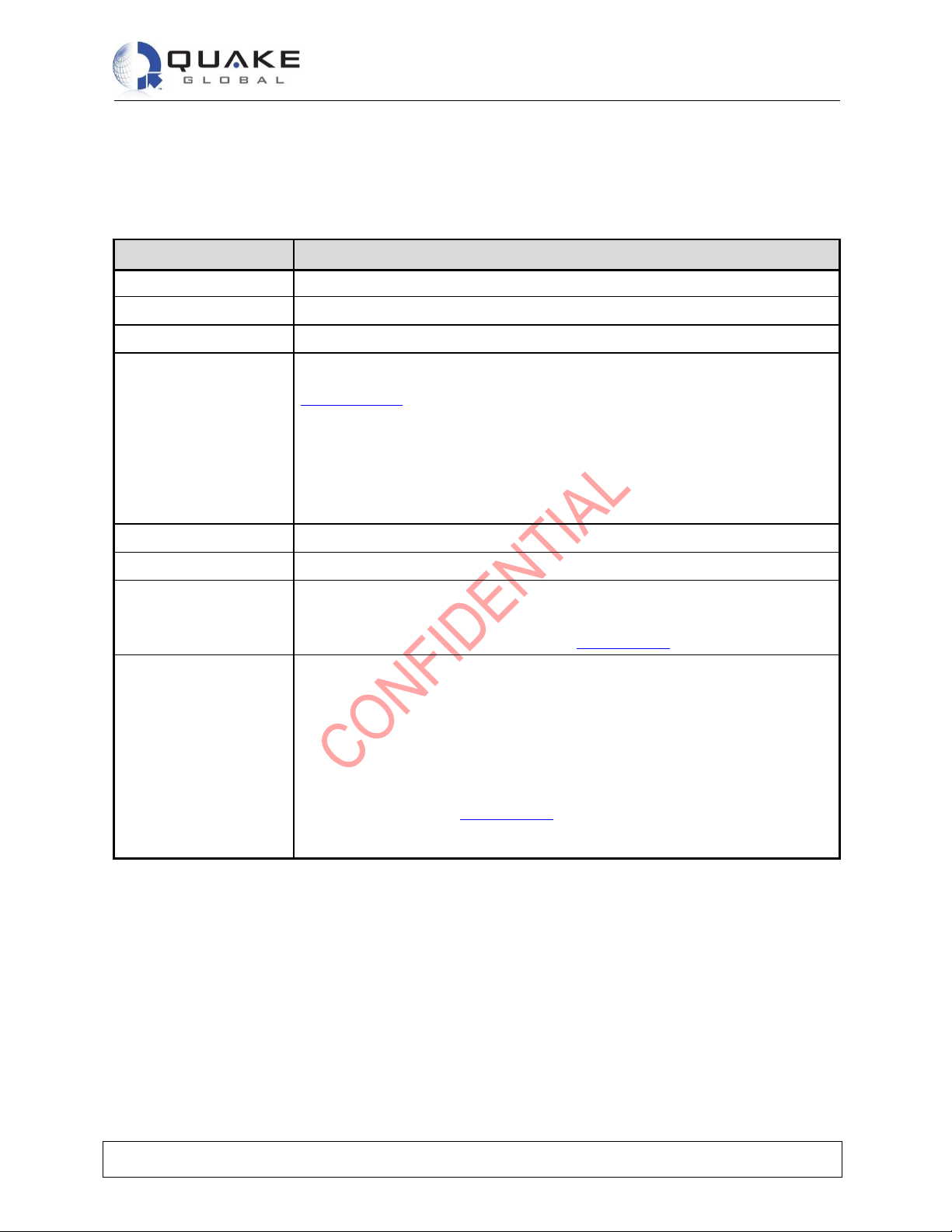
4.3 RF interface specifications
The RF interface requirements for the QLOCATE are summarized in Table 4-2 below.
Table 4-2: General RF parameters
Parameter
Value
Frequency range
1616 MHz to 1626.5 MHz
Duplexing method
TDD (Time Domain Duplex)
Input/Output impedance
50Ω
Multiplexing method
TDMA/FDMA
4.4 Radio characteristics
Table 4-3 contains radio characteristics of the QLOCATE.
Table 4-3: Radio characteristics
Parameter
Value
Average power during a transmit slot (max)
1.6 W
Receiver sensitivity (typical level at module connector)
-117dBm
Max cable loss permitted
3dB
Link Margin – Downlink
13dB
Page 16
Technical Data Sheet
QLOCATE
Document Number 1158-0901 Rev E
This document contains confidential and proprietary information of Quake Global corporation. It may be used by recipient only for the purpose for which it was transmitted and
will be returned upon request or when no longer needed by recipient. Disclosure to unauthorized third parties or duplication without the express written permission of Quake
Global is prohibited. © 2018 QUAKE GLOBAL, INC. - All rights reserved.
CONFIDENTIAL
Information classified
Confidential
- Do not copy (See last page for obligations)
Page 12
5 Ratings and certifications
5.1 Ratings
Table 5-1: Environmental ratings
Parameter
Rating
Operating temperature
-40C to +85C
Storage temperature
-40C to +85C
Low pressure
Up to 4 hours at 15000 ft elevation pressure
Humidity
Relative humidity range of 0% to 95% non-condensing at 65C
MIL SPEC 810E, Method 507.3 with test conditions.
Procedure I, Cycle 2
Procedure 1 simulates natural environmental cycles. It is conducted on test items
which are open to a frequently ventilated environment, Cycle 2 sconfiget temperature
at 24 deg C constant with humidity maintained at 95% minimum.
Test Duration: 15 Cycles (15 days )
Cyclic humidity
Temperature/Cyclic Humidity Test, 5 days at -10C to 65C at 85% relative humidity
Thermal shock
-40C to 85C (30 minutes at each temp, 10 cycles)
Mechanical shock
20G, saw tooth profile, over an 11 msec period. (Three positive and three negative
shocks in each of three mutually perpendicular axes.)
SAEJ1455 shock requirements and those in MIL-STD-810E.
Vibration
20 Hz to 2 KHz, 8 Grms vibration profile in each of three mutually perpendicular axes,
1 hour per axis,
10 Hz to 150 HZ, 0.5 g square/Hz vibration profile in each of three mutually
perpendicular axes, 1 hour per axis.
10 Hz to 150 HZ, 0.05 g^2/Hz vibration, 16 hours on each of three orthogonal axes
5 Hz to 20 Hz , 0.05 g^2/hz, and from 20 to 150 Hz, -3 dB/octave, 1 hour each axes.
Vibration requirements in MIL-STD-810E.
SAEJ1455 vibration requirements
Page 17

Technical Data Sheet
QLOCATE
Document Number 1158-0901 Rev E
This document contains confidential and proprietary information of Quake Global corporation. It may be used by recipient only for the purpose for which it was transmitted and
will be returned upon request or when no longer needed by recipient. Disclosure to unauthorized third parties or duplication without the express written permission of Quake
Global is prohibited. © 2018 QUAKE GLOBAL, INC. - All rights reserved.
CONFIDENTIAL
Information classified
Confidential
- Do not copy (See last page for obligations)
Page 13
5.2 Certifications
Table 5-2: Certifications
Regulatory
Approval
Tests
Rating / /Notes
Radio
EMC
Electrical/
Mechanical/
Operational/
Safety
Iridium SBD
Iridium Network Certification
FCC
FCC CFR47
parts 2, 15,
and 25
EN61000-4-2 : 1995/A2 : 2001 Part
4.2
EN61000-4-3 : 2002 Part 4.3
EN61000-4-4 : 2004
EN61000-4-6 : 1996/A1 : 2001 Part
4.6
EN55022:2006
FCC ID: PB5NQLOCATE
See * FCC note below.
Industry
Canada
Industry
Canada
RSS170 Iss. 1,
Rev 1,
November 6,
1999
IC: 4650A-QLOCATE
See ** Industry Canada note
below.
CE
ETSI EN 301
441 V1.1.1
(2000-05)
ETSI EN301 489-1 V1.8.1(2008-04)
ETSI EN 301 489-20 V1.2.1(2002-11)
EN60950-1:2006
Part 1
0168
* FCC note
FCC Part 15 Class B - Radio Frequency Interference (RFI) (FCC 15.105)
Operation is subject to the following two conditions:
1. This device may not cause harmful interference.
2. This device must accept any interference received, including interference that may cause undesired
operation.
RF Exposure
This equipment complies with FCC radiation exposure limits set forth for an uncontrolled environment.
This equipment should be installed and operated with minimum distance 20cm between the radiator and
your body. This transmitter must not be co-located or operating in conjunction with any other antenna or
transmitter.
Unauthorized Changes
QUAKE has not approved any changes or modifications to this device by the user. Any changes or
modifications could void the user’s authority to operate the equipment.
Labelling Requirements for the Host device
The host device shall be properly labelled to identify the modules within the host device. The certification
label of the module shall be clearly visible at all times when installed in the host device, otherwise the
host device must be labelled to display the FCC ID and IC of the module, preceded by the words
"Contains transmitter module", or the word "Contains", or similar wording expressing the same meaning,
as follows:
Contains FCC ID: PB5NQLOCATE or Contains transmitter module FCC ID: PB5NQLOCATE
Page 18

Technical Data Sheet
QLOCATE
Document Number 1158-0901 Rev E
This document contains confidential and proprietary information of Quake Global corporation. It may be used by recipient only for the purpose for which it was transmitted and
will be returned upon request or when no longer needed by recipient. Disclosure to unauthorized third parties or duplication without the express written permission of Quake
Global is prohibited. © 2018 QUAKE GLOBAL, INC. - All rights reserved.
CONFIDENTIAL
Information classified
Confidential
- Do not copy (See last page for obligations)
Page 14
** Industry Canada note
Under Industry Canada regulations, this radio transmitter may only operate using an antenna of a type
and maximum (or lesser) gain approved for the transmitter by Industry Canada.
RF Exposure
To reduce potential radio interference to other users, the antenna type and its gain should be so chosen
that the equivalent isotropically radiated power (EIRP) is not more than that necessary for successful
communication.
This equipment complies with IC radiation exposure limits set forth for an uncontrolled environment. The
antenna should be installed and operated with minimum distance of 20 cm between the radiator and your
body. Antenna gain must be below: 3.0 dBi. This transmitter must not be co-located or operating in
conjunction with any other antenna or transmitter.
Unauthorized Changes
QUAKE has not approved any changes or modifications to this device by the user. Any changes or
modifications could void the user’s authority to operate the equipment.
This device complies with Industry Canada license-exempt RSS standard(s). Operation is subject to the
following two conditions:
1. This device may not cause interference.
2. This device must accept any interference, including interference that may cause undesired
operation of the device.
CAN ICES-3 (B) / NMB-3 (B)
This Class B digital apparatus complies with Canadian ICES-003.
Labelling Requirements for the Host device
The host device shall be properly labelled to identify the modules within the host device. The certification
label of the module shall be clearly visible at all times when installed in the host device, otherwise the
host device must be labelled to display the IC of the module, preceded by the words "Contains transmitter
module", or the word "Contains", or similar wording expressing the same meaning, as follows:
Contains FCC ID: PB5NQLOCATE or Contains transmitter module FCC ID: PB5NQLOCATE
Contains IC: 4650A-QLOCATE or Contains transmitter module IC: 4650A-QLOCATE
French translation:
Conformément à la réglementation d'Industrie Canada, le présent émetteur radio peut fonctionner
avec une antenne d'un type et d'un gain maximal (ou inférieur) approuvé pour l'émetteur par
Industrie Canada.
QUAKE n’approuve aucune modification apportée à l’appareil par l’utilisateur, quelle qu’en soit la nature.
Tout changement ou modification peuvent annuler le droit d’utilisation de l’appareil par l’utilisateur.
Dans le but de réduire les risques de brouillage radioélectrique à l'intention des autres
utilisateurs, il faut choisir le type d'antenne et son gain de sorte que la puissance isotrope
rayonnée équivalente (p.i.r.e.) ne dépasse pas l'intensité nécessaire à l'établissement d'une
communication satisfaisante.
Cet appareil est conforme aux limites d'exposition aux rayonnements de la IC pour un environnement non
contrôlé. L'antenne doit être installé de façon à garder une distance minimale de 20 centimètres entre la
source de rayonnements et votre corps. Gain de l'antenne doit être ci-dessous: 3.0 dBi. L'émetteur ne
doit pas être colocalisé ni fonctionner conjointement avec à autre antenne ou autre émetteur.
Page 19

Technical Data Sheet
QLOCATE
Document Number 1158-0901 Rev E
This document contains confidential and proprietary information of Quake Global corporation. It may be used by recipient only for the purpose for which it was transmitted and
will be returned upon request or when no longer needed by recipient. Disclosure to unauthorized third parties or duplication without the express written permission of Quake
Global is prohibited. © 2018 QUAKE GLOBAL, INC. - All rights reserved.
CONFIDENTIAL
Information classified
Confidential
- Do not copy (See last page for obligations)
Page 15
The QLOCATE complies with the standards for Radio Emissions Compliance,
Electromagnetic Compatibility, and AC Safety in the United States, European Union
and Canada, for host systems that provide safe connections to power supply and
external antenna or a cable distribution system.
Le présent appareil est conforme aux CNR d'Industrie Canada applicables aux appareils radio exempts
de licence. L'exploitation est autorisée aux deux conditions suivantes : (1) l'appareil ne doit pas produire
de brouillage, et (2) l'utilisateur de l'appareil doit accepter tout brouillage radioélectrique subi, même si le
brouillage est susceptible d'en compromettre le fonctionnement.
Cet appareil numérique de classe B est conforme à la norme canadienne ICES-003.
L'appareil hôte doit être étiqueté comme il faut pour permettre l'identification des modules qui s'y trouvent.
L'étiquette de certification du module donné doit être posée sur l'appareil hôte à un endroit bien en vue en
tout temps. En l'absence d'étiquette, l'appareil hôte doit porter une étiquette donnant le FCC ID et le IC du
module, précédé des mots « Contient un module d'émission », du mot « Contient » ou d'une formulation
similaire exprimant le même sens, comme suit:
Contains FCC ID: PB5NQLOCATE or Contains transmitter module FCC ID: PB5NQLOCATE
Contains IC: 4650A-QLOCATE or Contains transmitter module IC: 4650A-QLOCATE
Note:
Page 20

Technical Data Sheet
QLOCATE
Document Number 1158-0901 Rev E
This document contains confidential and proprietary information of Quake Global corporation. It may be used by recipient only for the purpose for which it was transmitted and
will be returned upon request or when no longer needed by recipient. Disclosure to unauthorized third parties or duplication without the express written permission of Quake
Global is prohibited. © 2018 QUAKE GLOBAL, INC. - All rights reserved.
CONFIDENTIAL
Information classified
Confidential
- Do not copy (See last page for obligations)
Page 16
5.3 Regulatory Compliance
• FCC
• CE
• J1455
Page 21
Technical Data Sheet
QLOCATE
Document Number 1158-0901 Rev E
This document contains confidential and proprietary information of Quake Global corporation. It may be used by recipient only for the purpose for which it was transmitted and
will be returned upon request or when no longer needed by recipient. Disclosure to unauthorized third parties or duplication without the express written permission of Quake
Global is prohibited. © 2018 QUAKE GLOBAL, INC. - All rights reserved.
CONFIDENTIAL
Information classified
Confidential
- Do not copy (See last page for obligations)
Page 17
6 Technical drawings
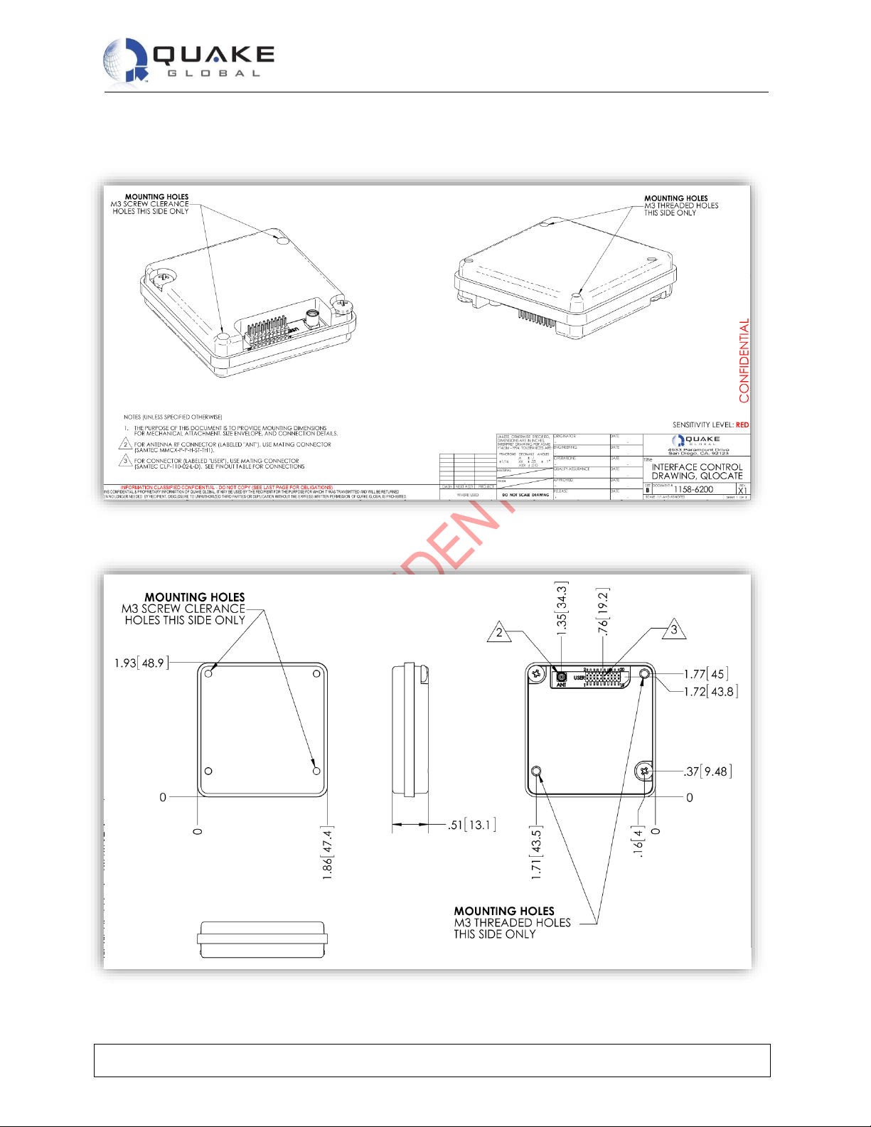
Figure 6-1: QLOCATE dimensions (1)
Figure 6-2: QLOCATE dimensions (2)
Page 22
Technical Data Sheet
QLOCATE
Document Number 1158-0901 Rev E
This document contains confidential and proprietary information of Quake Global corporation. It may be used by recipient only for the purpose for which it was transmitted and
will be returned upon request or when no longer needed by recipient. Disclosure to unauthorized third parties or duplication without the express written permission of Quake
Global is prohibited. © 2018 QUAKE GLOBAL, INC. - All rights reserved.
CONFIDENTIAL
Information classified
Confidential
- Do not copy (See last page for obligations)
Page 18
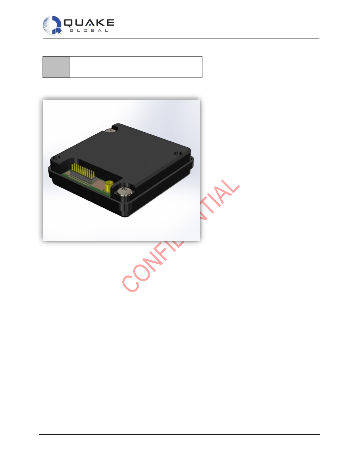
Table 6-1: QLOCATE dimensions
Weight
.08 lbs. (0.036 kg)
Size
1.92” x 1.86” x .51” (48.76mm x 47.24 x 12.95)
Figure 6-3: QLOCATE
Page 23
Technical Data Sheet
QLOCATE
Document Number 1158-0901 Rev E
This document contains confidential and proprietary information of Quake Global corporation. It may be used by recipient only for the purpose for which it was transmitted and
will be returned upon request or when no longer needed by recipient. Disclosure to unauthorized third parties or duplication without the express written permission of Quake
Global is prohibited. © 2018 QUAKE GLOBAL, INC. - All rights reserved.
CONFIDENTIAL
Information classified
Confidential
- Do not copy (See last page for obligations)
Page 19
7 Operation
7.1 Installation recommendations
• It is best to connect the UBATT (-) to chassis ground rather than to the (-) battery terminal.
• The input voltage range is: 5 ± 0.5 VDC.
• In order to protect wires installed within the engine compartment or along the undercarriage,
ensure that all wires are wrapped with wire loom.
7.1.1 Mounting
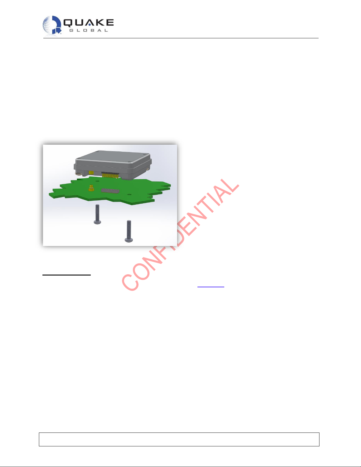
Figure 7-1: QLOCATE mounting example
Mounting notes:
1. The example of a host system motherboard footprint in Figure 7-1 is shown for illustrative purposes
only. The host system may require a different PCB layout or mechanical arrangement.
2. The QLOCATE is designed to be incorporated within a host system. It is therefore important that the
antenna or cable distribution system that feeds the host system be terminated in a robust RF
connector that is suitable for the end-application.
3. Safety isolation requirements for external antennas or cable distribution systems should also be taken
into account when designing the motherboard. A suitably safe design for the RF connections should
be incorporated into the host system motherboard, ideally using a chassis-bonded ground connection
to the antenna cable shield.
4. The surface below the modem should be a conductive ground plane to ensure that the modem bonds
to the motherboard ground system, thereby reducing the possibility of radiated emissions. This also
requires that the mounting screws be properly tightened to 7 pound-inches of torque.
Page 24
Technical Data Sheet
QLOCATE
Document Number 1158-0901 Rev E
This document contains confidential and proprietary information of Quake Global corporation. It may be used by recipient only for the purpose for which it was transmitted and
will be returned upon request or when no longer needed by recipient. Disclosure to unauthorized third parties or duplication without the express written permission of Quake
Global is prohibited. © 2018 QUAKE GLOBAL, INC. - All rights reserved.
CONFIDENTIAL
Information classified
Confidential
- Do not copy (See last page for obligations)
Page 20
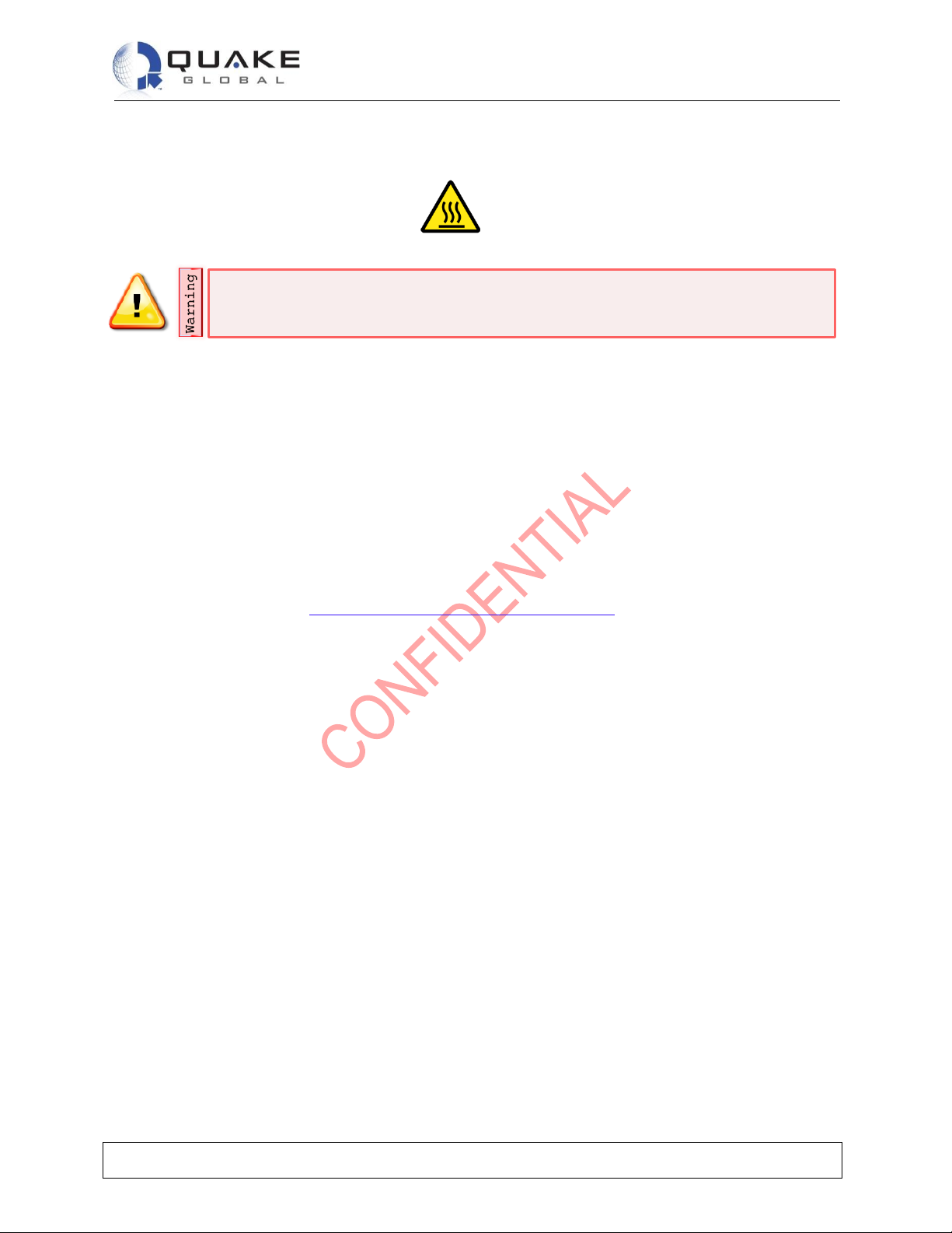
Although the modem dissipates very little power, its use in ambient temperatures in
excess of 60 deg C will make the caseworks notably hot.
5. The modem is to be installed in a “service access only” area not accessible by untrained personnel
and must be protected from inadvertent contact.
WARNING
HOT SURFACE
DO NOT TOUCH
7.2 Basic operation
• The QLOCATE with GPS/GLONASS contains both a GPS module and an Iridium satellite module.
Only one module is utilized at a time. Pin 5 is the line that controls which module is being used.
• For QLOCATEs without GPS/GLONASS, power must be applied and pin 5 should be asserted to turn
on the QLOCATE, and de-asserted to turn off the QLOCATE.
7.2.1 Iridium satellite
When there is potential on pin 5 (3.3V), the Iridium module is utilized. The default baud rate for the
Iridium module is 19200. From a terminal window set at 19200, basic AT commands can be used to
control the module. Section 8.1 - Example: Send and receive a message outlines the steps to power on
and send or retrieve a message.
7.2.2 GPS option
When there is no potential on pin 5 (0V), the GPS module will be utilized rather than the Iridium module.
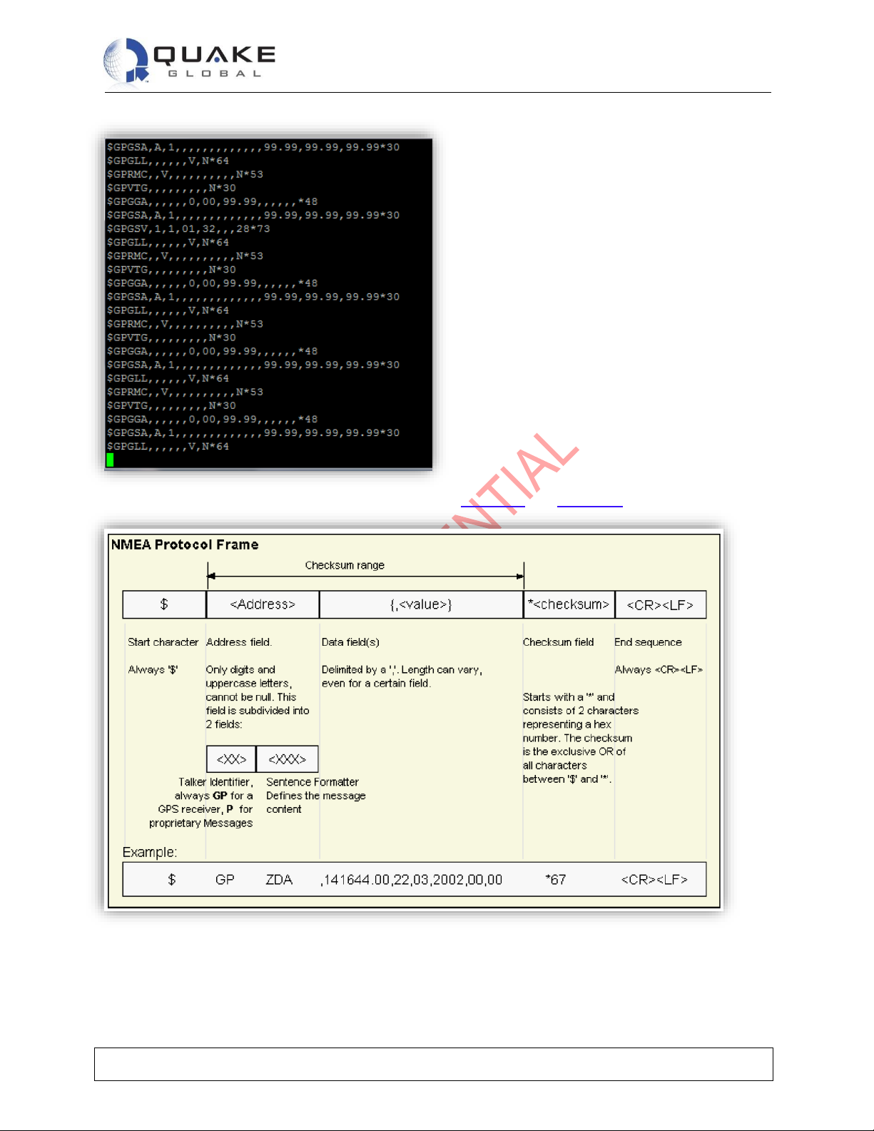
The default baud rate for the GPS module is 9600. Through a terminal window the GPS NMEA strings
can be seen. The module automatically starts a GPS read to acquire a fix when utilized.
Page 25
Technical Data Sheet
QLOCATE
Document Number 1158-0901 Rev E
This document contains confidential and proprietary information of Quake Global corporation. It may be used by recipient only for the purpose for which it was transmitted and
will be returned upon request or when no longer needed by recipient. Disclosure to unauthorized third parties or duplication without the express written permission of Quake
Global is prohibited. © 2018 QUAKE GLOBAL, INC. - All rights reserved.
CONFIDENTIAL
Information classified
Confidential
- Do not copy (See last page for obligations)
Page 21
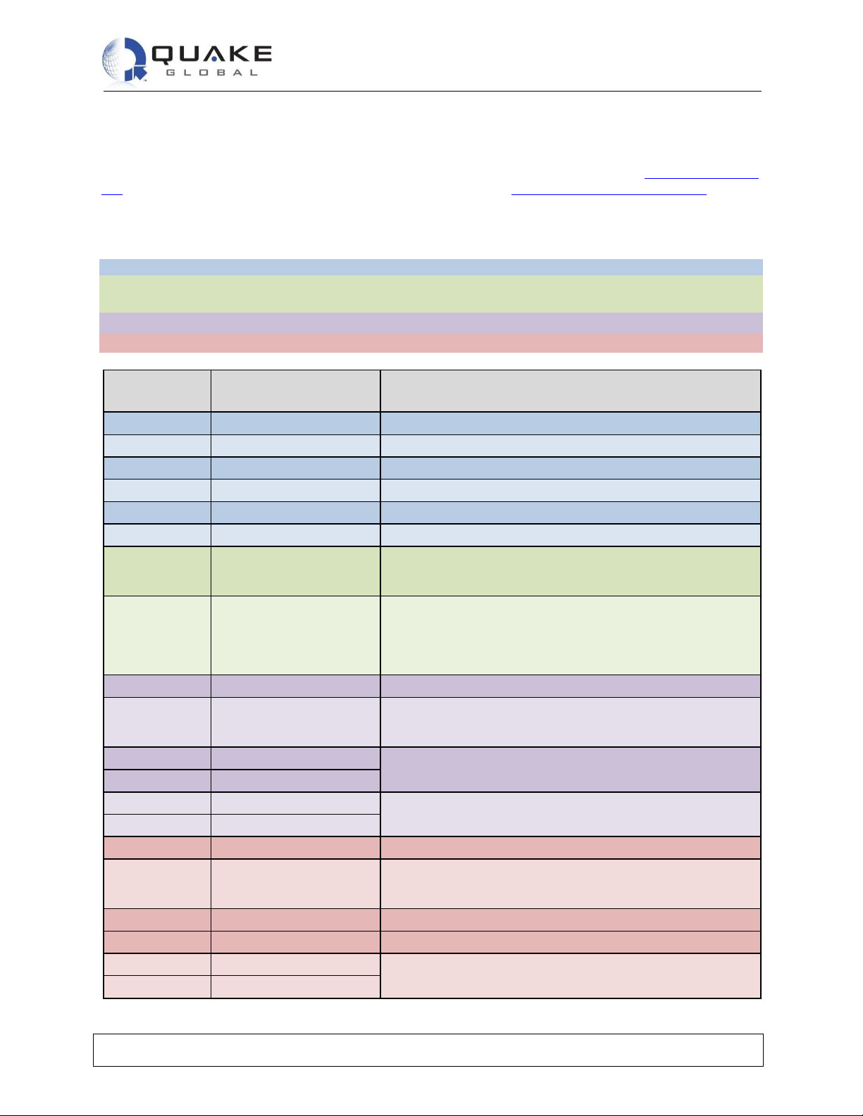
The structure of the NMEA messages is shown below in Figure 7-2 and Figure 7-3.
Figure 7-2: NMEA message structure (1)
Page 26

Technical Data Sheet
QLOCATE
Document Number 1158-0901 Rev E
This document contains confidential and proprietary information of Quake Global corporation. It may be used by recipient only for the purpose for which it was transmitted and
will be returned upon request or when no longer needed by recipient. Disclosure to unauthorized third parties or duplication without the express written permission of Quake
Global is prohibited. © 2018 QUAKE GLOBAL, INC. - All rights reserved.
CONFIDENTIAL
Information classified
Confidential
- Do not copy (See last page for obligations)
Page 22
Figure 7-3: NMEA message structure (2)
Page 27
Technical Data Sheet
QLOCATE
Document Number 1158-0901 Rev E
This document contains confidential and proprietary information of Quake Global corporation. It may be used by recipient only for the purpose for which it was transmitted and
will be returned upon request or when no longer needed by recipient. Disclosure to unauthorized third parties or duplication without the express written permission of Quake
Global is prohibited. © 2018 QUAKE GLOBAL, INC. - All rights reserved.
CONFIDENTIAL
Information classified
Confidential
- Do not copy (See last page for obligations)
Page 23
8 AT Command Set Description
The QLOCATE is configured and operated through the use of AT commands. See the ISU AT Command
Set for the full set of AT commands and responses. See also the Iridium SBD Developer’s Guide for
information on how SBD operates on the Iridium system.
8.1 Example: Send and receive a message
1. Power up the FA; it will attempt a registration.
2. Upon successful registration, a message check is performed to see if any MT messages are queued;
2 messages are found.
3. The first 90-byte message is sent and then retrieved from the MT buffer.
4. The second 90-byte message is sent and then retrieved from the MT buffer.
To SSD
(from FA)
To FA (from SSD)
Description
Apply power to the SBD Subscriber Device (SSD)
Wait for DSR to become asserted
AT+SBDREG?
Query the SSD registration status
+SBDREG:0
SSD is detached, i.e. un-registered
AT+SBDREG
Tell the SSD to register for ring alerts
+SBDREG:2,0
SSD is now registered
AT+SBDSX
The Field Application software running on the DTE (FA) initiates
extended status check (values updated during +SBDREG
session).
+SBDSX: 0,23,0,-1,0,2
SSD indicates that no ring alert is present but that 2 messages
are queued at the Gateway SBD Subsystem (GSS). (The ring
alert value will only change to 1 if ring alerts are enabled and a
message is received at the GSS while the modem is powered on
and registered)
AT+SBDIX
FA initiates an SBD session to download message
+SBDIX:0,23,1,237,90,1
SSD informs FA that a 90-byte message was successfully
received with MTMSN 237, and that one additional MT message
is queued at the GSS
AT+SBDRB
FA retrieves the received message from the SSD
<binary transfer>
AT+SBDD1
Clear the MT message buffer.
0 AT+SBDIX
FA initiates an SBD session to download the additional message
+SBDIX:0,24,1,238,90,0
SSD informs FA that a 90-byte message was successfully
received with MTMSN 238, and that no additional MT messages
are queued at the GSS
AT+SBDRB
FA retrieves the received message from the SSD
<binary transfer>
AT+SBDD1
Clear the MT message buffer
0
Page 28

Technical Data Sheet
QLOCATE
Document Number 1158-0901 Rev E
This document contains confidential and proprietary information of Quake Global corporation. It may be used by recipient only for the purpose for which it was transmitted and
will be returned upon request or when no longer needed by recipient. Disclosure to unauthorized third parties or duplication without the express written permission of Quake
Global is prohibited. © 2018 QUAKE GLOBAL, INC. - All rights reserved.
CONFIDENTIAL
Information classified
Confidential
- Do not copy (See last page for obligations)
Page 24
9 Modem Software
For all questions or issues regarding software(current version, software update, etc), please contact the
Quake Customer Support.
Page 29

Technical Data Sheet
QLOCATE
Document Number 1158-0901 Rev E
This document contains confidential and proprietary information of Quake Global corporation. It may be used by recipient only for the purpose for which it was transmitted and
will be returned upon request or when no longer needed by recipient. Disclosure to unauthorized third parties or duplication without the express written permission of Quake
Global is prohibited. © 2018 QUAKE GLOBAL, INC. - All rights reserved.
CONFIDENTIAL
Information classified
Confidential
- Do not copy (See last page for obligations)
Page 25
10 Appendix A – Glossary of terms
DTE
Data Terminal Equipment
FA
The Field Application software running on the DTE.
GSS
Gateway SBD Subsystem
MO
Mobile Originated (Iridium network) – messages that are sent from the modem.
MT
Mobile Terminated (Iridium network) – messages that are sent to the modem.
N/C
No Connect
SBD
Short Burst Data
SSD
SBD Subscriber Device
Page 30

Technical Data Sheet
QLOCATE
Document Number 1158-0901 Rev E
This document contains confidential and proprietary information of Quake Global corporation. It may be used by recipient only for the purpose for which it was transmitted and
will be returned upon request or when no longer needed by recipient. Disclosure to unauthorized third parties or duplication without the express written permission of Quake
Global is prohibited. © 2018 QUAKE GLOBAL, INC. - All rights reserved.
CONFIDENTIAL
Information
classified Confidential
- Do not copy
.
Page 26
CONFIDENTIALITY OBLIGATIONS
This document contains sensitive information and is classified “CONFIDENTIAL”.
Its distribution is subject to the recipient’s signature of a Non-Disclosure Agreement (NDA).
At all times you should comply with the following security rules (Refer to the NDA for detailed obligations):
This document may not be altered in any way that removes or obscures the Confidentiality notices.
Keep this document locked away.
Additional copies can be provided on a “need to know basis”, please contact your QUAKE account
manager.
Please read carefully:
Information in this document is provided solely in connection with QUAKE Global, Inc. (“QUAKE”)
products. QUAKE™ reserves the right to make changes, corrections, modifications or improvements to
this document and the products and services described herein at any time, without notice.
All QUAKE products are sold pursuant to QUAKE’s terms and conditions of sale. Purchasers are solely
responsible for the choice, selection and use of QUAKE products and services described herein, and
QUAKE assumes no liability whatsoever relating to the choice, selection or use of QUAKE products and
services described herein. No license, express or implied, by estoppel or otherwise, to any intellectual
property rights is granted under this document. If any part of this document refers to any third party
products or services, it shall not be deemed a license grant by QUAKE for the use of such third party
products or services, or any intellectual property contained therein or considered as a warranty covering
the use in any manner whatsoever of such third party products or services or any intellectual property
contained therein.
UNLESS OTHERWISE SET FORTH IN QUAKE’S TERMS AND CONDITIONS OF SALE, QUAKE
DISCLAIMS ANY EXPRESS OR IMPLIED WARRANTY WITH RESPECT TO THE USE AND/OR SALE
OF QUAKE PRODUCTS INCLUDING, WITHOUT LIMITATION, IMPLIED WARRANTIES OF
MERCHANTABILITY, FITNESS FOR A PARTICULAR PURPOSE (AND THEIR EQUIVALENTS
UNDER THE LAWS OF ANY JURISDICTION), OR INFRINGEMENT OF ANY PATENT, COPYRIGHT
OR OTHER INTELLECTUAL PROPERTY RIGHT. UNLESS EXPRESSLY APPROVED IN WRITING
BY AN AUTHORIZED QUAKE REPRESENTATIVE, QUAKE PRODUCTS ARE NOT RECOMMENDED,
AUTHORIZED OR WARRANTED FOR USE IN MILITARY, AIRCRAFT, SPACE, LIFE SAVING, OR
LIFE SUSTAINING APPLICATIONS, NOR IN PRODUCTS OR SYSTEMS WHERE FAILURE OR
MALFUNCTION MAY RESULT IN PERSONAL INJURY, DEATH OR SEVERE PROPERTY OR
ENVIRONMENTAL DAMAGE.
Resale of QUAKE products with provisions different from the statements and/or technical features set
forth in this document shall immediately void any warranty granted by QUAKE for the QUAKE product or
service described herein and shall not create or extend in any manner whatsoever, any liability to
QUAKE.
QUAKE™ and the QUAKE logo are trademarks or registered trademarks of QUAKE Global. Information
in this document supersedes and replaces all information previously supplied.
© 2018 QUAKE GLOBAL, INC. - All rights reserved
www.quakeglobal.com
 Loading...