

Page 1

WebCCTV
Page 2

WebCCTV User Manual 2
Contents
CONTENTS .................................................................................................................................................................................................................. 2
PREFACE ..................................................................................................................................................................................................................... 6
1 INTRODUCTION ........................................................................................................................................................................................... 7
2 GETTING STARTED .................................................................................................................................................................................... 9
2.1 WEBCCTV IIS SPLIT ...................................................................................................................................................................................... 9
2.2 ACCESS WEBCCTV VIA INTERNET EXPLORER ........................................................................................................................................... 12
2.3 ACCESS WEBCCTV LOCALLY ...................................................................................................................................................................... 14
2.4 ADD WEBCCTV AS TRUSTED SITE ............................................................................................................................................................... 16
2.5 ADD WEBCCTV AS DEFAULT HOMEPAGE ................................................................................................................................................... 17
3 VIDEO MANAGER...................................................................................................................................................................................... 18
3.1 VIDEO MANAGER CONTROL PANEL ............................................................................................................................................................. 18
3.2 USERS ............................................................................................................................................................................................................. 19
3.2.1 General Information ............................................................................................................................................................................. 19
3.2.1.1 The Operator/User Account ......................................................................................................................................................... 20
3.2.1.2 The Administrator Account ......................................................................................................................................................... 20
3.2.2 Users - Add New User .......................................................................................................................................................................... 21
3.2.3 Change Your Password ........................................................................................................................................................................ 23
3.2.4 User Actions Log................................................................................................................................................................................... 24
3.2.4.1 Log Search .................................................................................................................................................................................... 24
3.2.4.2 Event Logger Configuration ........................................................................................................................................................ 26
3.2.5 Connected Users ................................................................................................................................................................................... 26
3.3 SETTINGS ........................................................................................................................................................................................................ 28
3.3.1 Cameras ................................................................................................................................................................................................. 29
3.3.1.1 Camera Search Wizard ................................................................................................................................................................. 30
3.3.1.1.1 IP Address ................................................................................................................................................................................. 31
3.3.1.1.2 Authentication .......................................................................................................................................................................... 31
3.3.1.2 Camera Wizard ............................................................................................................................................................................. 33
3.3.1.2.1 Name & Type ........................................................................................................................................................................... 33
3.3.1.2.2 Connection ................................................................................................................................................................................ 34
3.3.1.2.3 Live View ................................................................................................................................................................................. 35
3.3.1.2.4 Recordings ................................................................................................................................................................................ 36
3.3.1.2.5 Activity...................................................................................................................................................................................... 38
3.3.1.2.6 PTZ ............................................................................................................................................................................................ 40
3.3.1.2.7 Virtual Patrol ............................................................................................................................................................................ 41
3.3.1.2.8 Users .......................................................................................................................................................................................... 43
3.3.1.2.9 Audio ......................................................................................................................................................................................... 43
3.3.1.3 Network Video Server Wizard .................................................................................................................................................... 44
3.3.1.3.1 Name & Type ........................................................................................................................................................................... 45
3.3.1.3.2 Connection ................................................................................................................................................................................ 45
3.3.1.3.3 Video Settings........................................................................................................................................................................... 46
3.3.1.3.4 Name ......................................................................................................................................................................................... 46
3.3.1.3.5 Recordings ................................................................................................................................................................................ 47
3.3.1.3.6 Activity...................................................................................................................................................................................... 47
3.3.1.3.7 PTZ ............................................................................................................................................................................................ 49
3.3.1.3.8 Virtual Patrol ............................................................................................................................................................................ 50
3.3.1.3.9 Users .......................................................................................................................................................................................... 51
3.3.2 Alarms .................................................................................................................................................................................................... 52
3.3.2.1 Picolo I/O Proxy ........................................................................................................................................................................... 53
3.3.2.1.1 Name ......................................................................................................................................................................................... 53
3.3.2.1.2 Configuration ............................................................................................................................................................................ 54
3.3.2.1.3 Outputs ...................................................................................................................................................................................... 54
3.3.2.2 PMD I/O Device ........................................................................................................................................................................... 55
3.3.2.2.1 Name ......................................................................................................................................................................................... 55
3.3.2.2.2 Configuration ............................................................................................................................................................................ 56
3.3.2.2.3 Outputs ...................................................................................................................................................................................... 57
3.3.2.2.4 Delete PMD I/O Device ........................................................................................................................................................... 58
Version 4.9 Series
Page 3

WebCCTV User Manual 3
3.3.2.2.5 PMD I/O serial number ............................................................................................................................................................ 58
3.3.2.3 Generic Alarm Driver................................................................................................................................................................... 59
3.3.2.3.1 Name ......................................................................................................................................................................................... 59
3.3.2.3.2 Protocol ..................................................................................................................................................................................... 60
3.3.2.3.3 Connection ................................................................................................................................................................................ 60
3.3.2.4 RedLight Alarm Driver ................................................................................................................................................................ 60
3.3.2.4.1 Name ......................................................................................................................................................................................... 61
3.3.2.4.2 Protocol ..................................................................................................................................................................................... 61
3.3.2.4.3 Connection ................................................................................................................................................................................ 61
3.3.2.5 Alarm Configuration Wizard ....................................................................................................................................................... 62
3.3.2.5.1 Name ......................................................................................................................................................................................... 62
3.3.2.5.2 PTZ ............................................................................................................................................................................................ 63
3.3.2.5.3 Recordings ................................................................................................................................................................................ 64
3.3.2.5.4 FTP ............................................................................................................................................................................................ 65
3.3.2.5.5 Outputs ...................................................................................................................................................................................... 65
3.3.2.5.6 Notification ............................................................................................................................................................................... 66
3.3.2.5.7 Mail ........................................................................................................................................................................................... 67
3.3.2.5.8 SMS ........................................................................................................................................................................................... 67
3.3.3 POS ........................................................................................................................................................................................................ 69
3.3.3.1 Serial Port POS ............................................................................................................................................................................. 70
3.3.3.1.1 Device Name ............................................................................................................................................................................ 71
3.3.3.1.2 Device Protocol ........................................................................................................................................................................ 71
3.3.3.1.3 Device Connection ................................................................................................................................................................... 71
3.3.3.1.4 POS Name................................................................................................................................................................................. 72
3.3.3.1.5 POS Recordings........................................................................................................................................................................ 72
3.3.3.2 Generic POS ................................................................................................................................................................................. 73
3.3.3.2.1 Device Name ............................................................................................................................................................................ 74
3.3.3.2.2 Device Protocol ....................................................................................................................................................................... 74
3.3.3.2.3 Device Connection ................................................................................................................................................................... 74
3.3.3.2.4 POS Name................................................................................................................................................................................. 75
3.3.3.2.5 POS Recordings........................................................................................................................................................................ 75
3.3.3.3 TP.Net ........................................................................................................................................................................................... 76
3.3.3.3.1 Device Name ............................................................................................................................................................................ 77
3.3.3.3.2 Device Protocol ........................................................................................................................................................................ 77
3.3.3.3.3 Device Connection ................................................................................................................................................................... 78
3.3.3.3.4 POS Name................................................................................................................................................................................. 78
3.3.3.3.5 POS Recordings........................................................................................................................................................................ 79
3.3.3.4 NAMOS ........................................................................................................................................................................................ 80
3.3.3.4.1 Device Name ............................................................................................................................................................................ 80
3.3.3.4.2 Device Protocol ........................................................................................................................................................................ 80
3.3.3.4.3 Device Connection ................................................................................................................................................................... 81
3.3.3.4.4 POS Name................................................................................................................................................................................ 81
3.3.3.4.5 POS Recordings........................................................................................................................................................................ 82
3.3.3.5 Quadrox POS Printer .................................................................................................................................................................... 83
3.3.3.5.1 Device Name ............................................................................................................................................................................ 84
3.3.3.5.2 Device Protocol ........................................................................................................................................................................ 84
3.3.3.5.3 Device Connection ................................................................................................................................................................... 84
3.3.3.5.4 POS Name................................................................................................................................................................................. 85
3.3.3.5.5 POS Recordings........................................................................................................................................................................ 85
3.3.4 Storage Manager .................................................................................................................................................................................. 87
3.3.4.1 Adding, configuring & deleting a Volume ................................................................................................................................. 87
3.3.4.1.1 Location .................................................................................................................................................................................... 88
3.3.4.1.2 Cameras..................................................................................................................................................................................... 89
3.3.4.1.3 Storage Parameters ................................................................................................................................................................... 89
3.3.4.2 Advanced Storage Settings .......................................................................................................................................................... 91
3.3.4.2.1 Movie Lifetime ......................................................................................................................................................................... 91
3.3.4.2.2 Alarms ....................................................................................................................................................................................... 91
3.3.4.2.3 POS............................................................................................................................................................................................ 92
3.3.4.3 Detailed Storage Information ...................................................................................................................................................... 93
3.3.5 Single View ............................................................................................................................................................................................ 95
3.3.5.1 Frame rate ..................................................................................................................................................................................... 95
3.3.5.2 Sequence ....................................................................................................................................................................................... 95
Version 4.9 Series
Page 4

WebCCTV User Manual 4
3.3.6 Mosaics .................................................................................................................................................................................................. 97
3.3.7 Web Publishing ..................................................................................................................................................................................... 99
3.3.8 Network Settings ................................................................................................................................................................................. 100
3.3.9 Network Video Recorders ................................................................................................................................................................... 101
3.3.9.1 Network Video Recorder Wizard .............................................................................................................................................. 101
3.3.10 Certificate Management ..................................................................................................................................................................... 103
3.3.10.1 Self-signed certificates ............................................................................................................................................................... 103
3.3.10.2 CA signed certificates ................................................................................................................................................................ 104
3.4 INFO .............................................................................................................................................................................................................. 105
3.4.1 System Info .......................................................................................................................................................................................... 105
3.4.1.1 System Configuration ................................................................................................................................................................. 106
3.4.1.1.1 Saving Configuration ............................................................................................................................................................. 106
3.4.1.1.2 Restoring Configuration......................................................................................................................................................... 106
3.4.1.2 System Information .................................................................................................................................................................... 107
3.4.2 Network Diagnostics........................................................................................................................................................................... 108
3.4.2.1 Port Scanning .............................................................................................................................................................................. 109
3.4.2.2 Camera Scanning ........................................................................................................................................................................ 109
3.4.3 Load ..................................................................................................................................................................................................... 110
3.4.4 Server Messages Log .......................................................................................................................................................................... 111
3.4.4.1 Log Search .................................................................................................................................................................................. 111
3.4.4.2 Event Logger Configuration ...................................................................................................................................................... 113
3.4.5 System Downloads .............................................................................................................................................................................. 114
4 VIDEO BROWSER .................................................................................................................................................................................... 115
4.1 VIDEO BROWSER CONTROL PANEL ............................................................................................................................................................ 115
4.2 LIVE .............................................................................................................................................................................................................. 116
4.2.1 Single View .......................................................................................................................................................................................... 117
4.2.1.1 Sequences .................................................................................................................................................................................... 118
4.2.1.2 Mosaics ....................................................................................................................................................................................... 118
4.2.1.3 Low/High Bandwidth Mode ...................................................................................................................................................... 119
4.2.1.4 Snapshots .................................................................................................................................................................................... 119
4.2.1.5 PTZ .............................................................................................................................................................................................. 119
4.2.1.6 Digital Zoom ............................................................................................................................................................................... 120
4.2.1.7 Audio ........................................................................................................................................................................................... 121
4.2.1.8 Quick Playback ........................................................................................................................................................................... 122
4.2.1.9 Full Screen Mode ....................................................................................................................................................................... 122
4.2.2 Mosaic View ........................................................................................................................................................................................ 123
4.2.2.1 Sequences .................................................................................................................................................................................... 123
4.2.2.2 Mosaics ....................................................................................................................................................................................... 124
4.3 RECORDINGS ................................................................................................................................................................................................ 125
4.3.1 Select Time Period .............................................................................................................................................................................. 126
4.3.2 Single Playback ................................................................................................................................................................................... 127
4.3.2.1 Single Playback Controls ........................................................................................................................................................... 128
4.3.2.2 Switching sources ....................................................................................................................................................................... 128
4.3.2.3 Activity Level ............................................................................................................................................................................. 128
4.3.2.4 Slider ........................................................................................................................................................................................... 128
4.3.2.5 Full Screen Mode ....................................................................................................................................................................... 128
4.3.2.6 Low/High Bandwidth Mode ...................................................................................................................................................... 129
4.3.2.7 Snapshots .................................................................................................................................................................................... 129
4.3.2.8 Digital Zoom ............................................................................................................................................................................... 130
4.3.3 Synchronized Playback ....................................................................................................................................................................... 130
4.3.3.1 Synchronized Playback Controls ............................................................................................................................................... 131
4.3.3.2 Switching sources ....................................................................................................................................................................... 132
4.3.3.3 Slider ........................................................................................................................................................................................... 132
4.3.3.4 Full Screen Mode ....................................................................................................................................................................... 132
4.3.4 Smart Search ....................................................................................................................................................................................... 133
4.3.4.1 Smart Search Interface ............................................................................................................................................................... 133
4.3.4.2 Smart Search Playback Controls ............................................................................................................................................... 136
4.3.4.3 Full Screen Mode ....................................................................................................................................................................... 137
4.3.4.4 Low/High Bandwidth Mode ...................................................................................................................................................... 137
4.3.4.5 Snapshots .................................................................................................................................................................................... 138
4.3.4.6 Digital Zoom ............................................................................................................................................................................... 138
Version 4.9 Series
Page 5

WebCCTV User Manual 5
4.3.5 Movie Export ....................................................................................................................................................................................... 138
4.3.5.1 Creating Export........................................................................................................................................................................... 139
4.3.5.2 Saving Export Files to Hard Disk .............................................................................................................................................. 139
4.3.5.3 Saving Export Files to CD ......................................................................................................................................................... 140
4.3.5.4 Checking Digital Signature ........................................................................................................................................................ 142
4.3.6 Alarms .................................................................................................................................................................................................. 148
4.3.7 POS ...................................................................................................................................................................................................... 149
4.4 ALARMS ....................................................................................................................................................................................................... 150
4.4.1 View Alarm Movie .............................................................................................................................................................................. 151
4.4.2 Export Alarm Movie ........................................................................................................................................................................... 151
4.4.3 Slider .................................................................................................................................................................................................... 151
4.4.4 Alarm Playback Controls ................................................................................................................................................................... 152
4.4.5 Low/High Bandwidth Mode ............................................................................................................................................................... 152
4.4.6 Snapshots ............................................................................................................................................................................................. 152
4.4.7 Digital Zoom ....................................................................................................................................................................................... 153
4.5 POS .............................................................................................................................................................................................................. 154
APPENDIX A ........................................................................................................................................................................................................... 155
APPENDIX B ........................................................................................................................................................................................................... 160
GLOSSARY .............................................................................................................................................................................................................. 165
Version 4.9 Series
Page 6

WebCCTV User Manual 6
Preface
This document
This manual is intended for administrators and operators of a WebCCTV Video Recorder and
is applicable for WebCCTV software version 4.5 and higher.
Safety Notices
Please observe all safety notes and instructions carefully when using this product.
Liability
The information in this publication is believed to be accurate in all respects. Quadrox assumes
no responsibility for incidental or consequential damages incurred directly or indirectly from
errors, omissions or discrepancies in connection with the furnishing, performance or use of
this manual. The information contained herein is subject to change without notice. Revisions
or new editions to this publication may be issued to incorporate such changes. All rights
reserved. Under the copyright laws, no part of this manual can be reproduced in any form
without written permission of Quadrox.
Legal considerations
Please check your local regional laws and regulations before using WebCCTV for
surveillance purposes. Camera surveillance maybe prohibited by laws, which may vary from
country to country.
Trademark Acknowledgments
Quadrox, WebCCTV, Internet Explorer, Windows are registered trademarks of the respective
holders.
Support Services
Should you require any technical assistance, please contact your installer. If your questions
cannot be answered immediately, your installer will forward your queries through the
appropriate channels to ensure a fast response.
Version 4.9 Series
Page 7

WebCCTV User Manual 7
1 Introduction
WebCCTV is a unique digital video surveillance solution, which combines three major
functions in one Network Video Recorder (NVR) or Digital Video Recorder (DVR): local
digital recording, multiplexing and simultaneous transmission of the video via existing
networks (TCP/IP). To a standard WebCCTV, up to 16 cameras can be permanently recorded
while multiple operators at different locations on the network are accessing the WebCCTV
device.
Being a networked device, WebCCTV utilizes two basic principles of the
Internet/Intranet technology:
WebCCTV works over the TCP/IP network protocol, which provides maximum
connectivity. This means that the existing computer network infrastructure can be
used eliminating extra installation expenses.
WebCCTV uses a web-based user interface to view live images, recordings, etc.
More specific it uses Microsoft Internet Explorer.
Remote and Local Monitoring
To remotely monitor the connected cameras, the
WebCCTV uses Web Browser technology. To
locally monitor video, the WebCCTV also
provides a local interface via a PC monitor
directly connected to the WebCCTV. This local
interface allows an operator to see live video
from the connected cameras without the need
for additional client computers on a network.
Continuous Activity-Based Recording
By default, a WebCCTV continuously records all images from all the connected cameras
based on activity detection. In this case, only movement is recorded. If there is no movement,
no recording takes place. If necessary, the WebCCTV can be set to record continuously.
Intelligent Storage Option
WebCCTV uses a first-in/first-out (FIFO) overwrite principle. Once the disk is full, the oldest
images are overwritten.
Semi-Continuous recording (recording based on activity detection) allows a WebCCTV to
store pre- and post-alarm video. Pre- and Post-alarm images are often more important than the
images at the time of the alarm event itself. Up to 5 minutes of pre- and post-alarm video can
be stored.
Version 4.9 Series
Page 8

WebCCTV User Manual 8
WebCCTV makes a distinction between common activity recordings and pre/post alarm
recordings. In the way that, alarm recordings have a higher storage priority and will not be
overwritten by non-alarm recordings.
The WebCCTV is operational even when no live monitoring occurs. While the
WebCCTV continuously records images from all the cameras, video is
transmitted from the server to the client only when an Internet browser is
connected to WebCCTV and someone is live-viewing images from one or more
cameras.
Version 4.9 Series
Page 9
WebCCTV User Manual 9
2 Getting Started
This chapter provides information to get you started using your WebCCTV. It covers the
following topics:
Accessing WebCCTV via Internet Explorer.
Accessing WebCCTV locally.
Setting up WebCCTV application as default homepage.
Add WebCCTV as a trusted site.
2.1 WebCCTV IIS Split
As stated before, the WebCCTV application is a real web application which increases the
flexibility and connectivity considerably. This web application is managed by IIS (Internet
Information Services) which is installed on a computer of choice which can run IIS.
Versions prior to version 4.0.8.0 only have the ability to install IIS on the Video
Server itself.
By having the option to install the web application (by using IIS) onto a computer of choice, it
is possible to simplify the connection and scalability of the global security installation as the
server itself and the web application don’t have to be installed on the same unit.
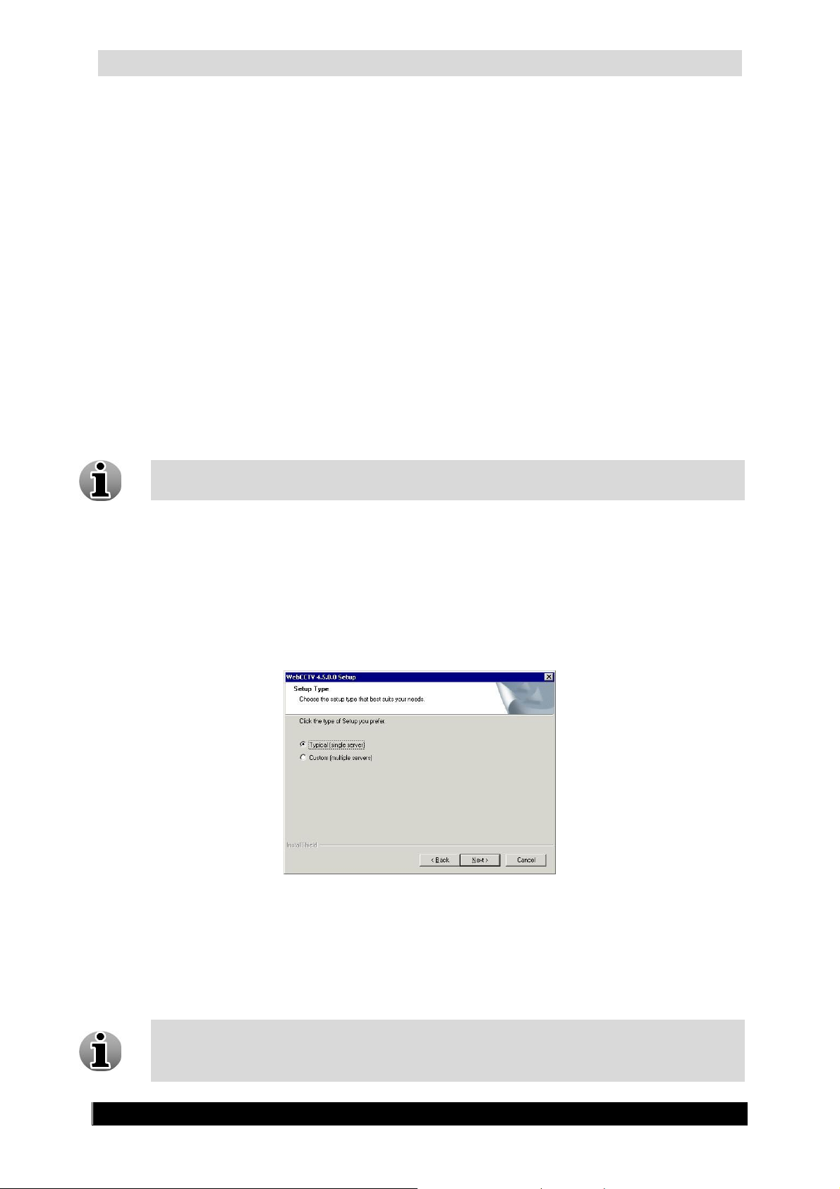
In the beginning of the installation, you will be able to choose whether to use the split
functionality or not. You must choose one of the options: typical or custom. The Typical
(single server) option will install the web application and the video server on the same
machine.
Setup Type Selection Screen
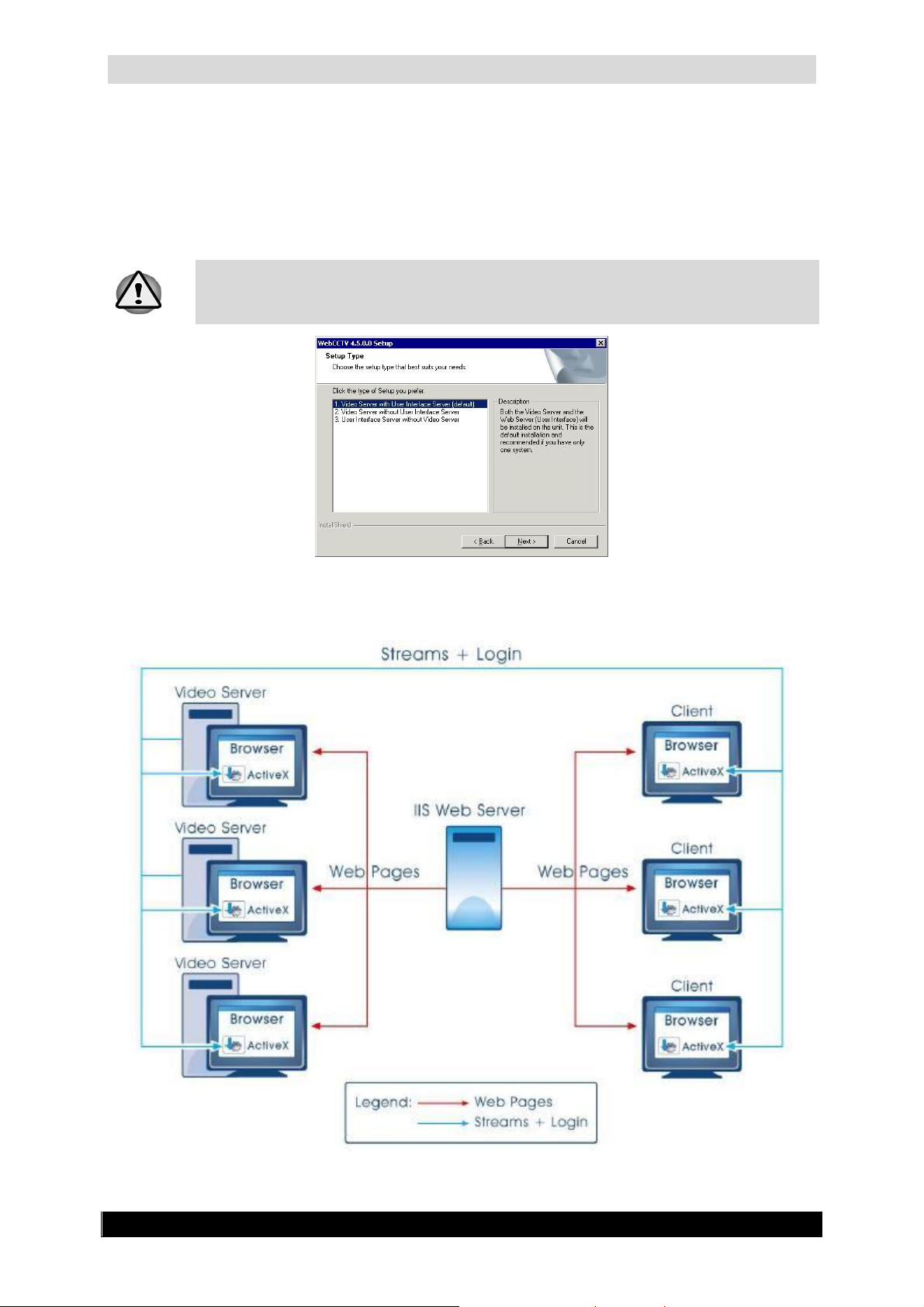
If Custom (multiple servers) is selected, there will be three possible options:
Video Server with User Interface Server (default) – Both the video server and the
web application will be installed on the unit. Option Typical (single server) or first
option in the Custom menu.
This is default installation and recommended if you have only one WebCCTV
system.
Version 4.9 Series
Page 10
WebCCTV User Manual 10
Video Server without User Interface Server – Only the Video Server is installed.
This means you have installed the Web Application (User Interface) on another
system. Option Custom (multiple severs).
User Interface Server without Video Server – Only the Web Application is
installed. Ideally this web application will be used as the central web application for
all the WebCCTV systems in your network. Option Custom (multiple severs).
You can choose one of the three options during the installation of your system by
selecting Custom. Ask your installer for more information if you didn’t install the
system yourself.
Setup Type Selection Screen
The following pictures give you an idea how it works:
Centralized IIS Server on separate unit
Version 4.9 Series
Page 11

WebCCTV User Manual 11
Centralized IIS Server on a Video Server
Let us explain how this works in reality!
If you have multiple Video Servers installed and have installed a centralized IIS server (On
one of the Video Server or even on a separate PC), then you can connect to each Video Server
by connecting first to the centralized Web Application by typing the IP of that unit. At that
time you can choose which server you want to connect to in the network from the extended
logon screen. In this case you only need to remember one IP address to connect to all your
WebCCTV servers.
This means that when you connect to a Video Server that also has the Web Application
installed you will need the basic logon screen shown below:
Basic Logon Screen
Version 4.9 Series
Page 12

WebCCTV User Manual 12
If you want to connect through the centralized Web Server, you have to use the extend logon
screen by clicking Options. There you select or type the video server IP or DNS name:
For more information about the configuration of this setup, see chapter 3.3.7.
Network Video Recorders where you can define all servers which are reachable
through a centralized Web Server.
You can choose which server you want to use as the default server to connect to. For
more information, see chapter 3.3.7. Network Video Recorders.
Extended Logon Screen
2.2 Access WebCCTV via Internet Explorer
WebCCTV automatically starts recording the moment it is turned on and booted. The
booting process takes about two minutes.
The WebCCTV can be accessed via Internet Explorer. This Internet Explorer
browser can reside on three places:
1. A capable client LAN PC: This is a PC in the same network as the WebCCTV
2. A capable client WAN PC: This is a PC on the wide area network. Your
router/firewall has to be configured properly in order to connect to
Only ‘ActiveX’ supporting Internet Browsers are designed to be used with the
WebCCTV. Internet browsers like Netscape, Opera and other browsers that do not
support ‘ActiveX’, are not suitable for use with WebCCTV.
WebCCTV.
3. The WebCCTV: On the desktop of the WebCCTV, you can click the video
browser icon which will open the Internet Explorer browser on the WebCCTV
itself automatically redirecting you to the WebCCTV server.
Version 4.9 Series
Page 13
WebCCTV User Manual 13
‘http://192.168.100.1/’
Start
Internet Explorer
http
To access the WebCCTV server via Internet Explorer, follow the steps below:
1. Obtain the exact IP address for the WebCCTV from your System Administrator and
make note of it for future reference.
is the factory default IP-address for a WebCCTV. Please note
that your installer could have changed it to fit the specifications of your own network.
2. Open Internet Explorer.
Click the
button on your PC or WebCCTV and find
in the
All Programs tab. An Internet Explorer link can often be found on the desktop.
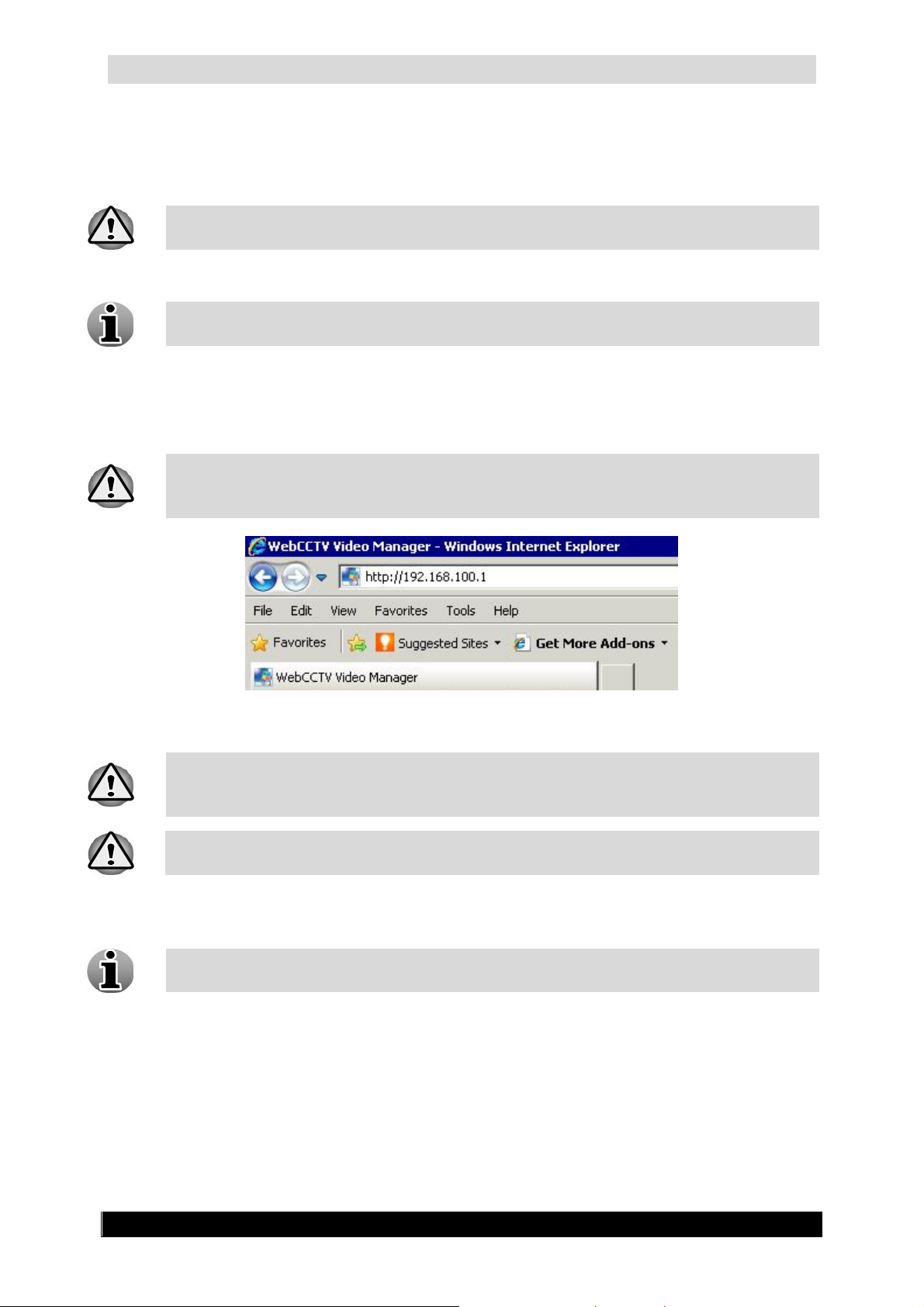
3. Once Internet Explorer is opened, click on the address field and enter the IP-address as
shown in the example below (without the quotes):
‘http://192.168.100.1/’
Make sure to include the
prefix into the IP-address. This is a protocol used for
communication with a World Wide Web server. Since WebCCTV uses the same
technology, the http prefix should be included.
WebCCTV IP-address
When you changed the TCP/IP communication port, you need to add the port in the
IP-address. For example, is you changed the TCP/IP port to 81 (80 is default port),
the IP-address becomes ‘http://192.168.100.1:81/’.
If you want to connect to a WebCCTV or GuardDVR, your IP-address becomes
‘http://192.168.100.1/WebCCTV’ or ‘http://192.168.100.1/guarddvr’
If the WebCCTV is accessed for the first time with a client PC, you will need to install the
ActiveX component. Follow the instructions on your screen.
Installation of the component is done (semi) automatically on the first connection to a
WebCCTV. The installation only has to be done once.
Version 4.9 Series
Page 14
WebCCTV User Manual 14
2.3 Access WebCCTV locally
The WebCCTV Local User Interface allows you to view video footage in real time by
connecting a monitor directly to WebCCTV while recording at the same time.
Compared to Internet Explorer access, accessing WebCCTV via the Local Interface
has limited user functionality. The Local Interface access does not consume much
CPU and memory. Accessing WebCCTV via Local Interface slightly increases image
quality.
To access WebCCTV locally, please follow the steps below:
1. Connect a monitor, a keyboard and a mouse directly to the WebCCTV.
2. By default, a standard Windows Login window will appear on the screen. Login with
administrative credentials.
Please contact your installer for the correct details.
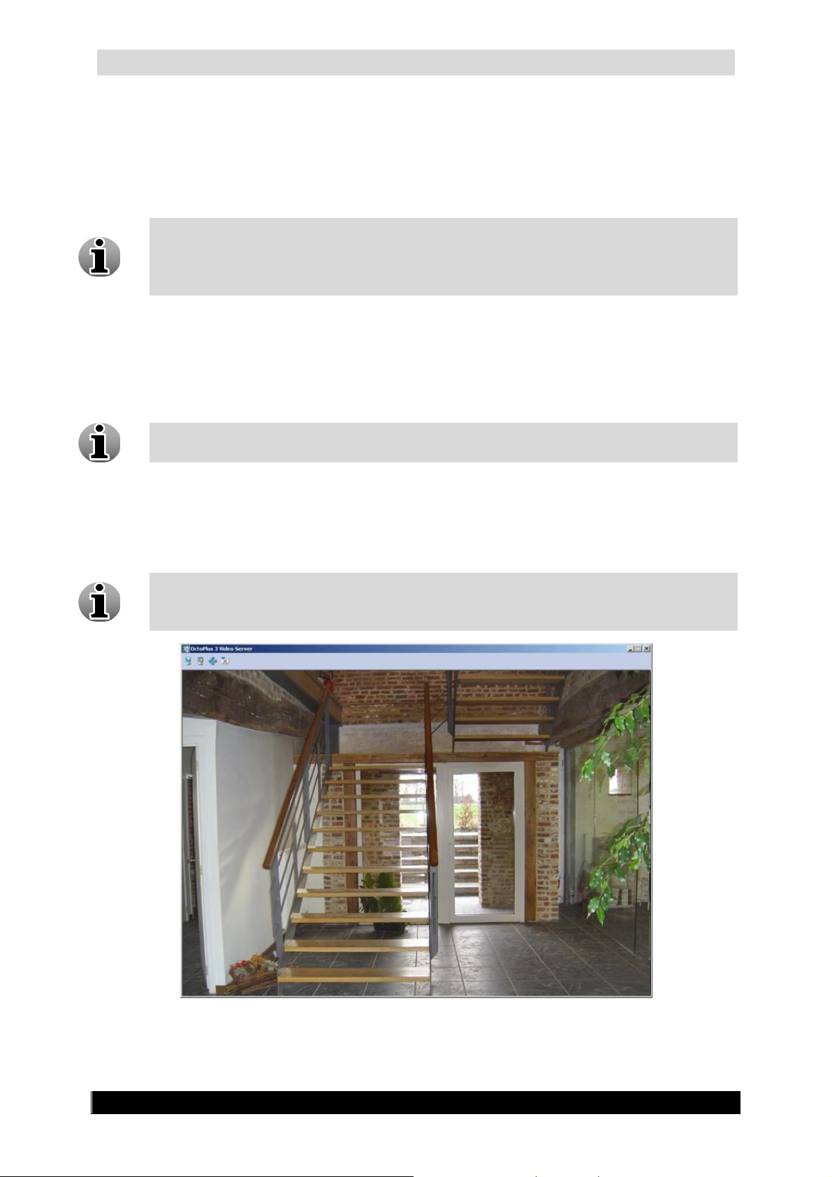
3. Depending on how you accessed the WebCCTV last time, you will see either a
WebCCTV Local Interface directly on the screen or a WebCCTV Local Interface icon
on the system tray in the right bottom corner.
4. Double click the Local Interface icon to restore the Local Interface.
It’s possible to configure the WebCCTV not to show the Windows logon screen after
a restart and go directly to the Local Interface. To achieve this double-click the icon
“Operator Mode” on the WebCCTV desktop.
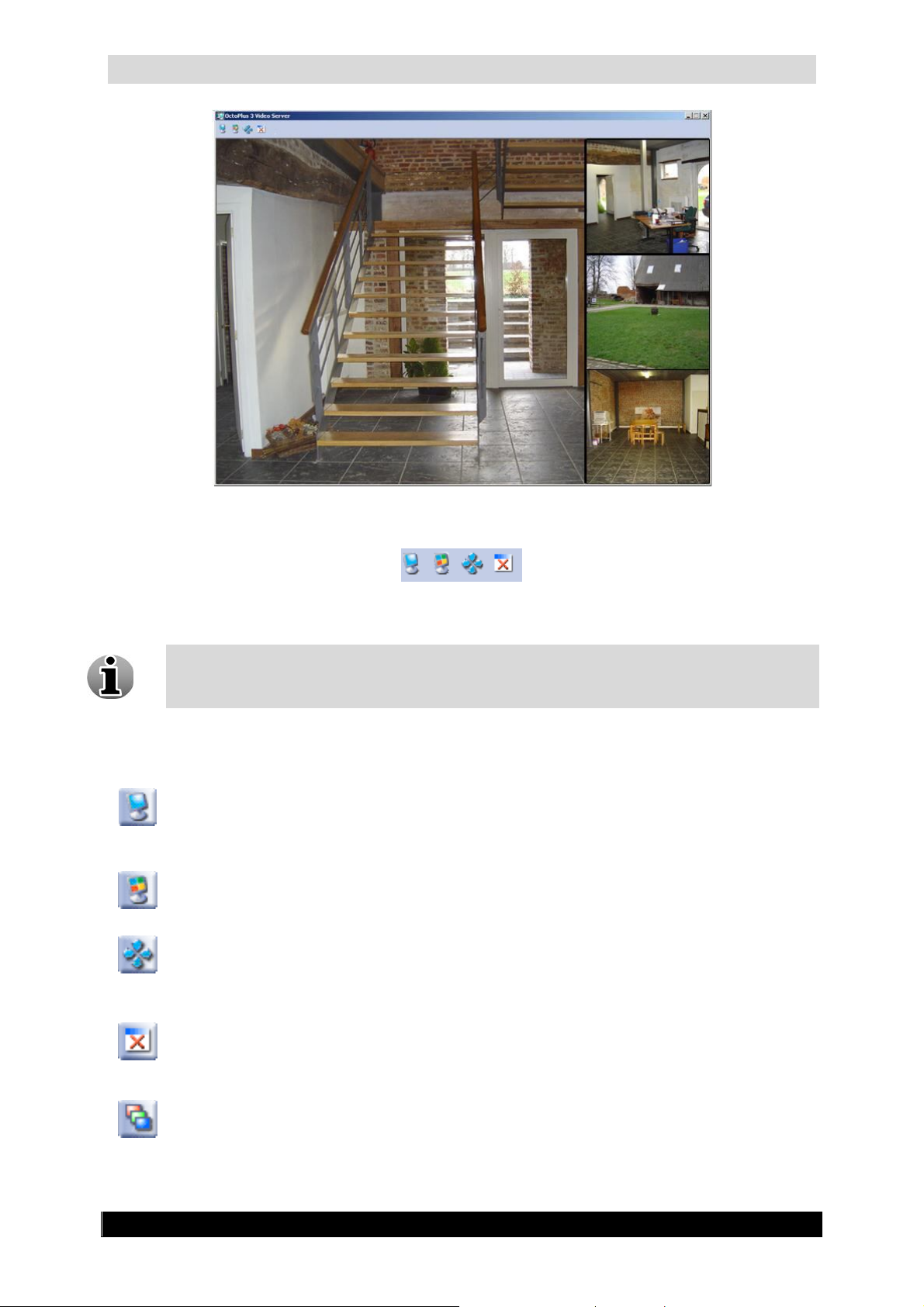
WebCCTV Local Interface Single View Screen
Version 4.9 Series
Page 15
WebCCTV User Manual 15
WebCCTV Local Interface Mosaic View Screen
WebCCTV Local Interface Control Panel
WebCCTV Local Interface provides basic Live view functionality (in Single or
Mosaic View). For complete WebCCTV functionality including settings, recordings,
exporting, and accessing the WebCCTV server via Internet Explorer.
WebCCTV Local Interface Buttons
Single View
Click on this button to access live view from a single camera.
Mosaic View
Click on this button to live view multiple cameras.
Full Screen Button
Click on this button to extend the application window to full screen view.
Close Child Windows Button
Click on this button to close all the windows on the screen
Change Mosaic View Button
This button is applicable only if more than 4 cameras are connected; it allows you
to jump from one mosaic view to another.
Version 4.9 Series
Page 16
WebCCTV User Manual 16
2.4 Add WebCCTV as trusted site
The trusted sites zone contains sites you trust; sites that you believe you can download or run
files from without worrying about damage to your computer or data. The default security
level for the trusted sites zone is Low, therefore, Internet Explorer will allow all cookies and
ActiveX controls from Web sites in this zone to be saved on your computer and read by the
Web site that created them. We recommend adding WebCCTV to the trusted sites zone.
To add the WebCCTV application as a trusted site, follow the steps below:
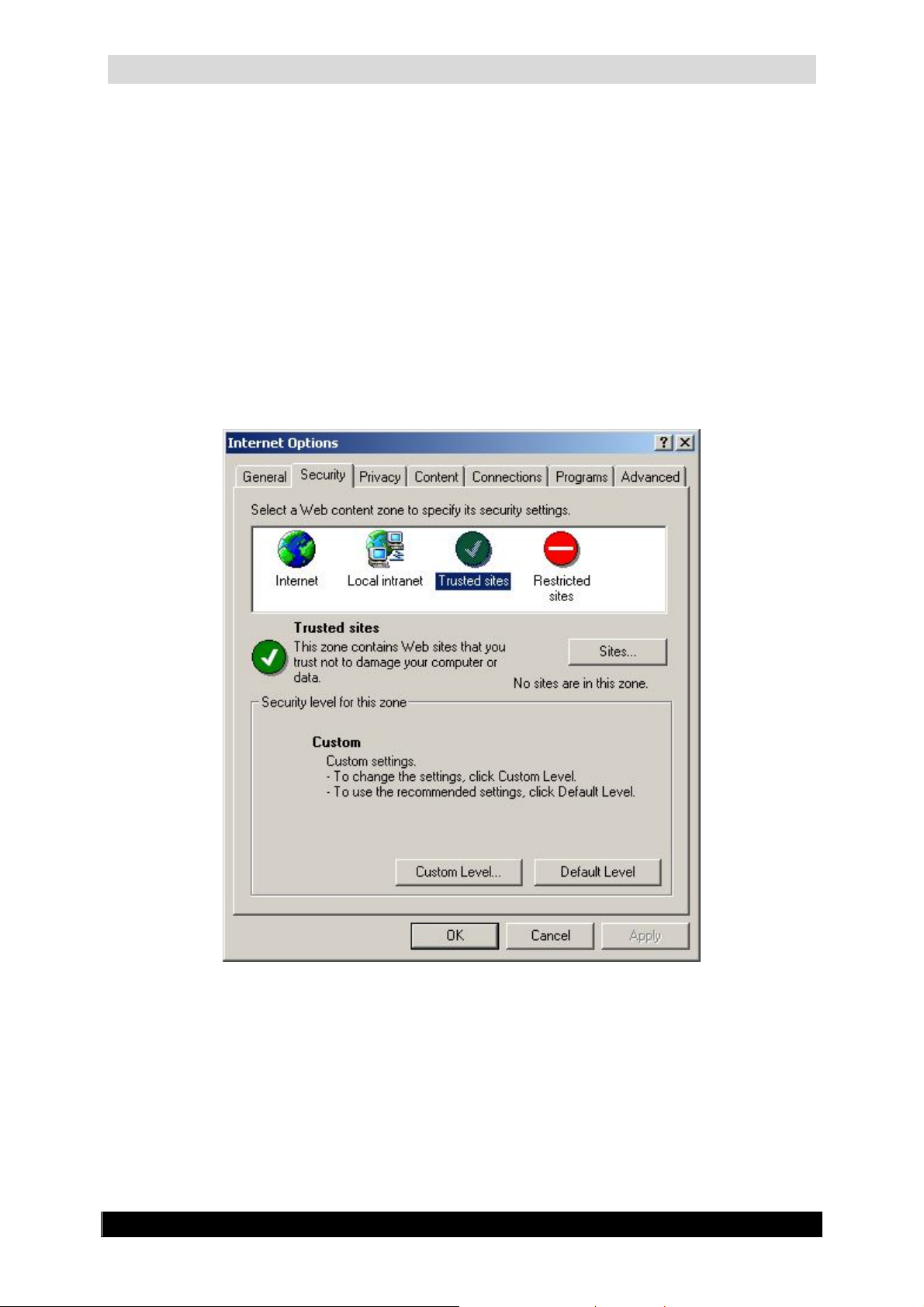
1. Select Tools on the Internet Explorer menu bar.
2. Select Internet Options.
3. Go to the Security tab. Select Trusted Sites there.
Internet Options Screen
Version 4.9 Series
Page 17
WebCCTV User Manual 17
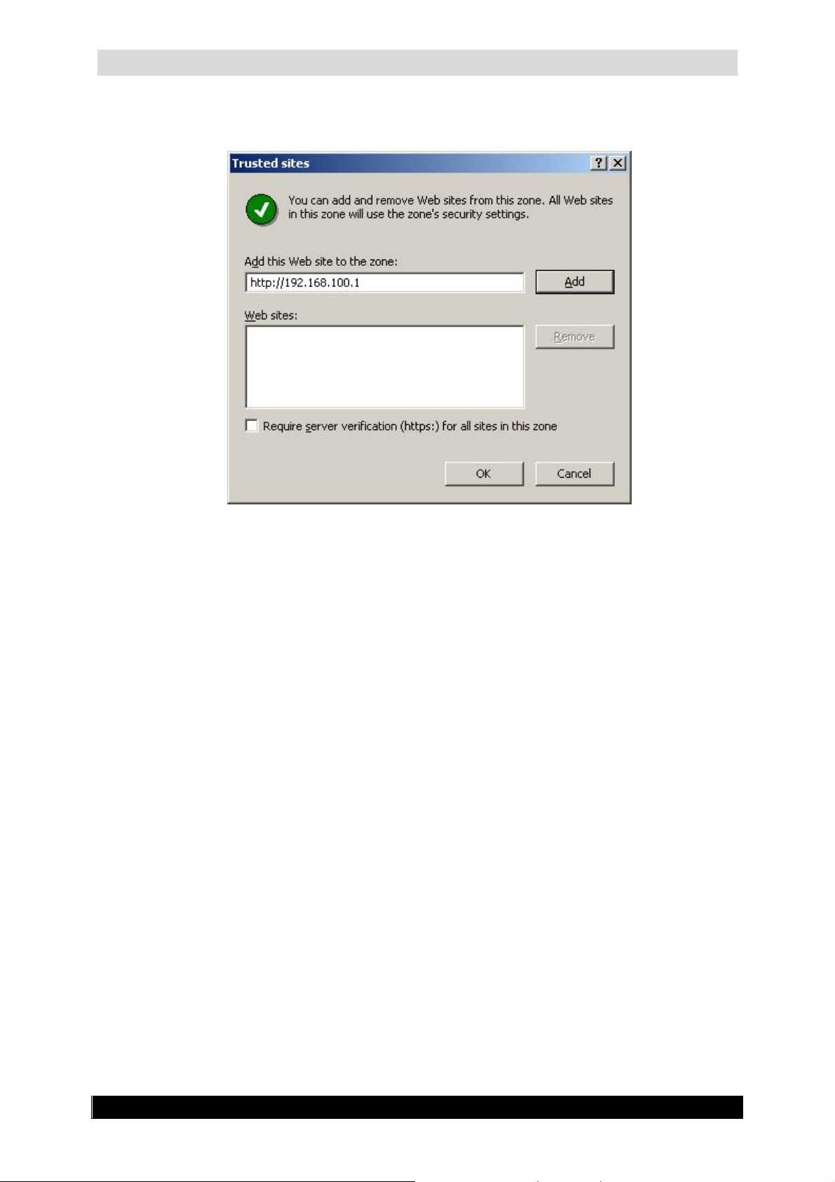
4. Click the Sites button. In the window that appears deselect Require server
verification (https:) for all sites in this zone check box.
Trusted Sites Screen
5. Specify correct WebCCTV server address in the corresponding field and click Add
button.
6. Address you specified appears in the Web sites filed.
7. Click OK.
2.5 Add WebCCTV as default homepage
To make WebCCTV a default start page on a client PC, follow the steps below:
1. Select Tools on the Internet Explorer menu bar.
2. Select Internet Options.
3. Select General.
4. Click Use Current button or enter http://192.168.100.1 IP-address (or the correct
WebCCTV IP-address) as your new default homepage.
Version 4.9 Series
Page 18
WebCCTV User Manual 18
3 Video Manager
To log on to the Video Manager application, you need administrative rights.
This chapter provides an overview of the WebCCTV Video Manager Control Panel and the
following WebCCTV functions:
Users
Server Settings
General Server Information
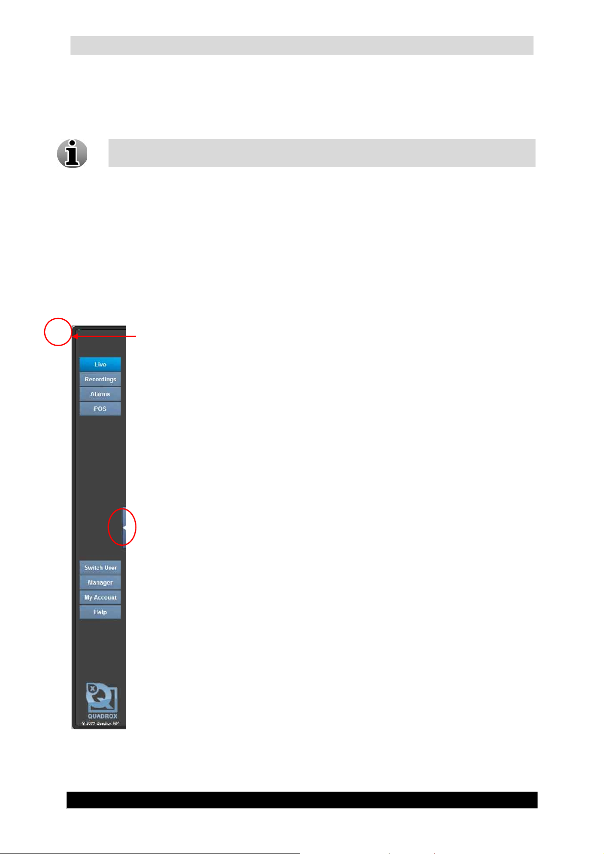
3.1 Video Manager Control Panel
Users
Click this button to access the Users screens where you can add or delete users,
give different user rights, check Connected Users and User Actions logs.
Settings
Click this button to change the WebCCTV settings to your requirements.
Info
Click this button to see general server information. This section also provides
access to Network Diagnostics, System Downloads and the Server logs.
Hide Control Panel
Click this button to hide or retrieve the control panel.
Restart
Click this button to restart the video server. Usually there’s no need to restart the
server unless the Restart button becomes red.
Video
Click this button to open the Video Browser application.
Help
Click this button to access WebCCTV Online help.
Log Off
Click this button to change user.
Exit
Click this button to exit the WebCCTV application.
Version 4.9 Series
Page 19

WebCCTV User Manual 19
3.2 Users
This chapter provides an overview of the Users section of WebCCTV.
3.2.1 General Information
WebCCTV is a multi user system capable of supporting an unlimited number of users. Every
registered user can have the following properties and user rights:
Property Description Limitation
Name Is used for the identification of the user Must be unique
Password Password related to the user for login No limitation
Language Preferable language for the user
User Rights Description
Live Access to live view
PTZ* Access to PTZ controls
Recordings Access to view the recorded video footage
Export Access to the export menu
Alarms Access to view alarms and related video footage
POS Access to view POS transactions and related video footage
User management** Access to change user privileges, view user actions log, view
connected users
System configuration** Access to modify system options
* setting presets are only available to users with administrator rights
** only available to users with administrator rights
Users with administrator rights can allow or block the viewing of certain cameras for
non-administrative users.
English, Dutch, French, Italian,
German, Spanish, Russian,
Ukrainian
By default WebCCTV has two user accounts:
Operator Account
Administrator Account
The default operator and administrator account can’t be deleted.
WebCCTV Users management is fully integrated into the Windows Operating
System users system, which results in very strong and safe access procedures.
Version 4.9 Series
Page 20
WebCCTV User Manual 20
3.2.1.1 The Operator/User Account
A non-administrative user can have different privileges and rights. He doesn’t have access to
the video manager application.
The default operator account can’t be deleted.
3.2.1.2 The Administrator Account
A user with Administrator Rights can:
Add new users
Change passwords
Delete users
Set user privileges
View User Actions Logs
View Connected Users
The default administrator account can’t be deleted.
A User name cannot be changed once it has been added. It can only be deleted. The
only parameters that can be changed are User Type, User Password, User Language
and User privileges.
Only an Administrator can grant, limit and edit user rights.
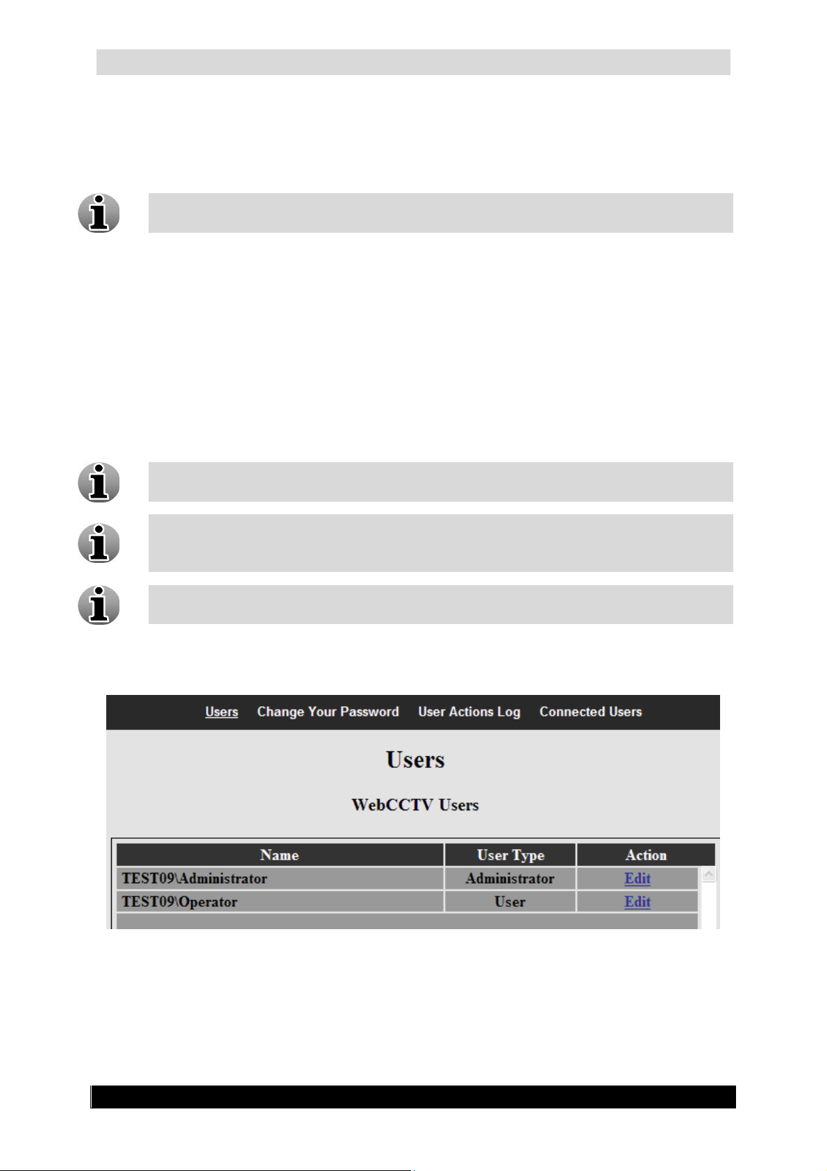
The screen shown below is displayed when you click on the Users button (TEST09 here is the
name of the PC; in new system it will be WEBCCTV):
Users Screen
Version 4.9 Series
Page 21

WebCCTV User Manual 21
The screen shown below is displayed with available Windows Users:
Users Screen with Windows Users
The subsections of the users menu are:
Users
Change Your Password
User Actions Log
Connected Users
3.2.2 Users - Add New User
By clicking the Users button, you are automatically taken to the Users menu. Adding a user
can be done in two ways:
Add an existing Windows user or domain user:
1. Click the Show Windows Users button
2. Select the existing Windows or domain user in the right panel and click the
left arrow. Your user is added as an Operator/User account. Click Edit. Go
now to Step 3.
Add a totally new user:
1. Click the Add New User button
2. Enter a Name. Go now to step 3.
Version 4.9 Series
Page 22
WebCCTV User Manual 22
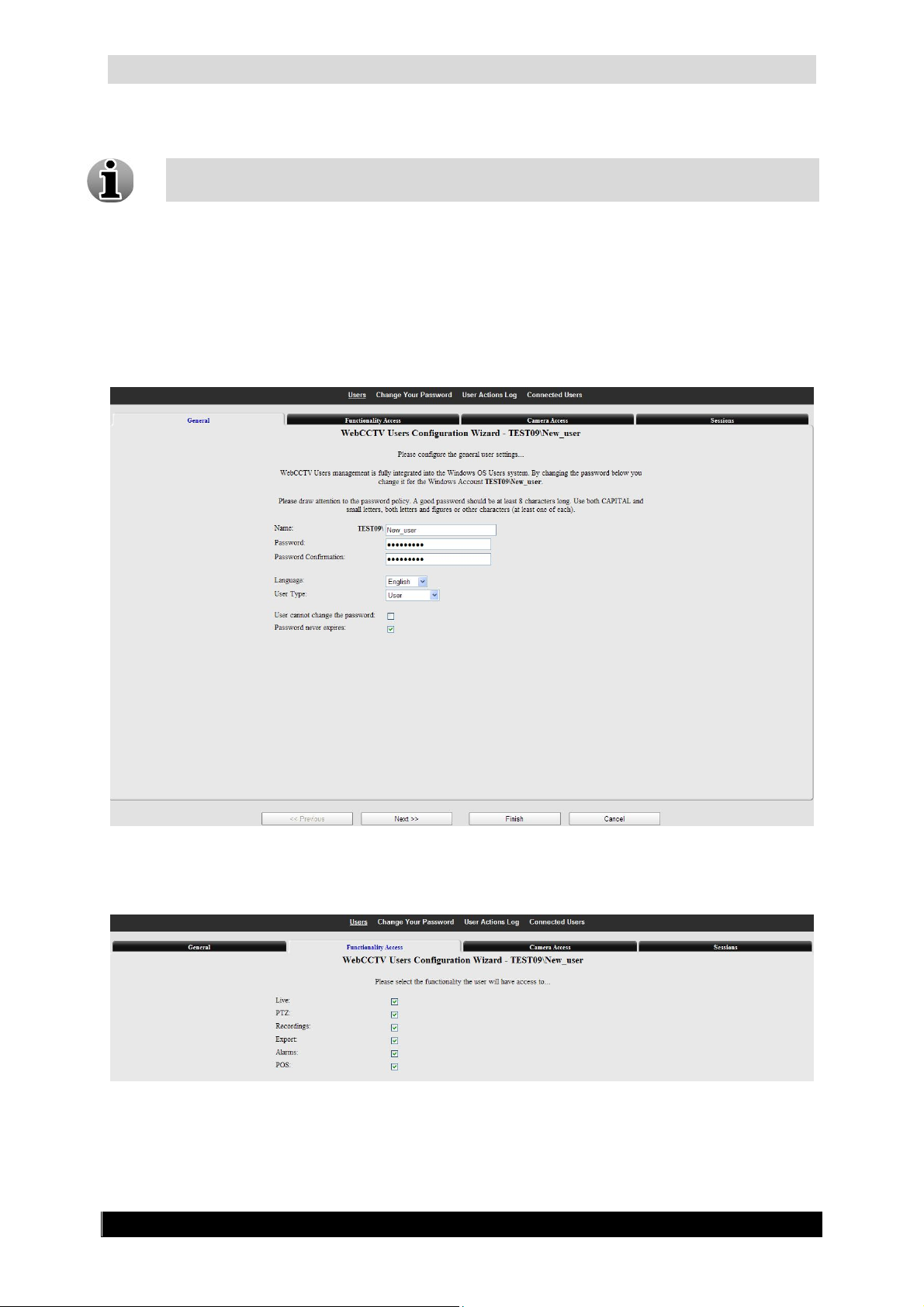
3. Enter a Password.
If you added an existing user, the assigned default password is videouser. We
strongly advise you to change the password.
4. Confirm the Password.
5. Select the interface language for the new user.
6. Define the ability for a user to change his password by (de)selecting the
User cannot change password check box.
7. Select the Password never expires check box if you don’t want the
password to expire. Otherwise a user will be forced to change the password
every 6 weeks.
8. Select the privileges for the new user.
Version 4.9 Series
General Screen
Functionality Access Screen
Page 23
WebCCTV User Manual 23
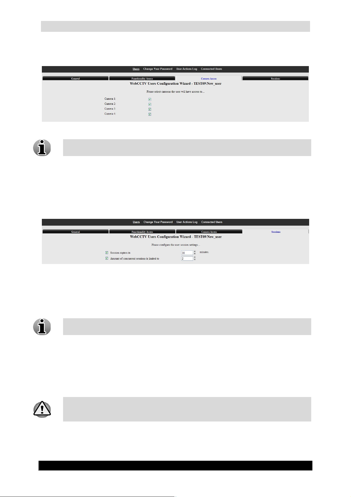
9. Define which cameras the user should be able to view on the Camera
Access tab.
Cameras Access Screen
By default, a newly-added user has access to all the cameras. You cannot limit access
to any functionalities and cameras for the user with Administrator rights.
10. Define the session parameters in the Sessions tab:
Session expires – Time after which the user will be disconnected from the
application. The user can login again afterwards. Time is measured in minutes.
Limit concurrent number of sessions – Number of sessions the user can open
simultaneously.
Sessions Screen
11. Click Finish to apply the changes.
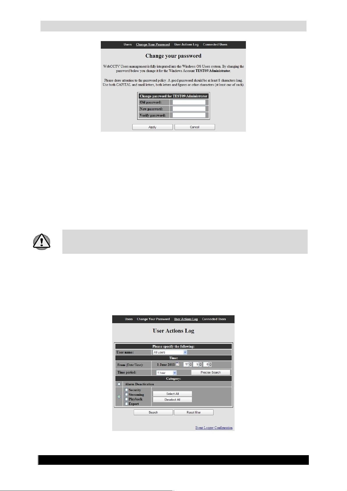
3.2.3 Change Your Password
Changing your password from time to time helps to protect your system from
unauthorized access.
To change the password, follow the steps below:
1. Enter the old password.
2. Enter the new password.
3. Enter the password confirmation.
4. Click Apply. The new password should be set now.
WebCCTV has no specific minimum password length limitation. When choosing a
password, try to take a password of at least 8 characters and use both capital and
small letters, both letters and figures or other characters (at least one of each).
Version 4.9 Series
Page 24
WebCCTV User Manual 24
Change Your Password Screen
Click on Cancel if you want to reset your form.
3.2.4 User Actions Log
WebCCTV stores all user actions in its User Actions Log. Example of user actions are live
views, recording views, user management changes, etc. This log is kept inside the Windows
operating system itself. Technically, it is kept inside a specific WebCCTV event log container
in the Windows event logging subsystem.
The amount of logged user actions (number of days contained in the log) depends on
the defined size of the event viewer. In normal circumstances, the log is large enough
to keep WebCCTV user logs for approximately 60 days.
3.2.4.1 Log Search
The search option allows you to retrieve all or specific actions that a certain user has
performed.
Log Search Screen
Version 4.9 Series
Page 25
WebCCTV User Manual 25
All possible actions are described in the following table and can be found in the picture
above.
Category Description
Security Activity of the user’s actions related to users management.
Streaming Activity of the cameras that have been watched in live view.
Recording View Activity of viewing video footage.
Export Activity of video footage files that were made for exporting.
To do a search, follow the steps below:
1. Specify the user for which you want to search (Optional).
2. Define the time frame in which you want to search.
3. Check the required categories checkboxes.
4. Click the Search button.
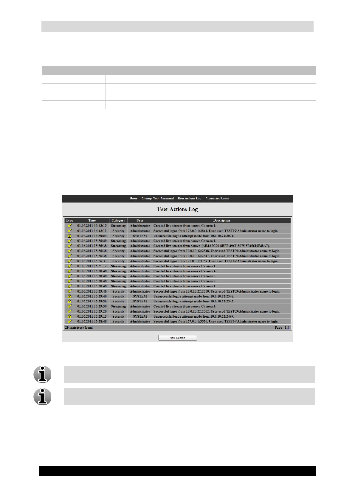
The figure below provides a sample overview of a User Actions Log (Security, Streaming,
Playback, Export):
User Actions Logbook Screen
User Actions Log allows you to check all user actions at all times.
In order to conduct a new log search, click on the New search button. The reset filter
button will clear all the checked boxes so that you can make a new selection.
Version 4.9 Series
Page 26

WebCCTV User Manual 26
3.2.4.2 Event Logger Configuration
The Event Logger Configuration defines the priority levels for the recorded events.
Depending on the selected option, WebCCTV will or will not store certain events.
Event Logger Configuration Screen
There are three Recorded Events levels:
Only Critical Events – WebCCTV stores the most important system events that occur
when proper WebCCTV performance is impossible, e.g. recording break, failure to
detect a system component, etc.
Important Events – WebCCTV stores system events labelled as “Only Critical
Events” and system events that play a significant role in the WebCCTV operating, e.g.
playback stream creating, system logging on, etc.
All Events – WebCCTV stores all system events.
To apply new settings, click Apply.
To cancel your changes, click Cancel.
To go back to the Users Actions Log screen, click Return.
Event Logger Settings functionality is unique for both User Actions Log and
Server Actions Log.
3.2.5 Connected Users
This screen enables you to observe specific information about connected users such as:
User Name – Name of the connected user.
Client IP Address – In the Client IP address column you can observe two parameters,
which are separated by a colon. IP address is the IP address of the client computer
from which a user is connected to the WebCCTV server. Port number is the TCP port
of the client computer through which a user is connected to the WebCCTV server.
Action – Click the Disconnect button to disconnect a user.
You can’t disconnect your own administrator session.
Version 4.9 Series
Page 27

WebCCTV User Manual 27
Connected Users Screen
In the Client IP address column you can observe two parameters, which are separated by a
colon:
IP address is the IP address of the client computer from which a user is connected to the
WebCCTV server.
Port number is the TCP port of the client computer from which a user is connected to the
WebCCTV server.
Click the Refresh button to update the Connected Users list.
Version 4.9 Series
Page 28
WebCCTV User Manual 28
3.3 Settings
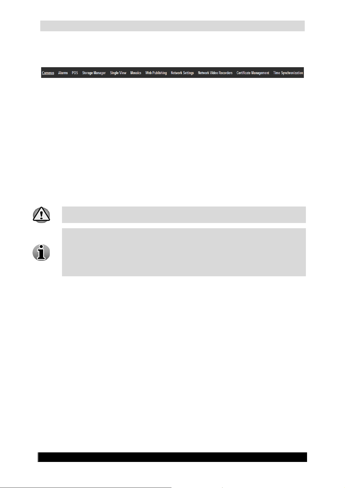
Settings Control Panel
The System Settings enable the user to change the WebCCTV behavior and adapt it to the
specific requirements. This chapter covers the following sections:
Cameras
Alarms
POS
Storage Manager
Single View
Mosaics
Network Settings
Certificate Management
Time Synchronization
Use System Settings with extreme caution, some of them can seriously affect the
WebCCTV performance and even stop proper functioning of the system.
Some of the System Settings require the WebCCTV to be rebooted for the settings to
take effect. You will be informed to reboot the WebCCTV server by a red message on
the screen. To restart the WebCCTV, click the Restart button which will turn red or
click the Restart now link that appears at the end of the message. While restarting the
server, you will get a message that the server is restarting. Once restarted, a successful
reboot message will be displayed.
Version 4.9 Series
Page 29
WebCCTV User Manual 29
3.3.1 Cameras
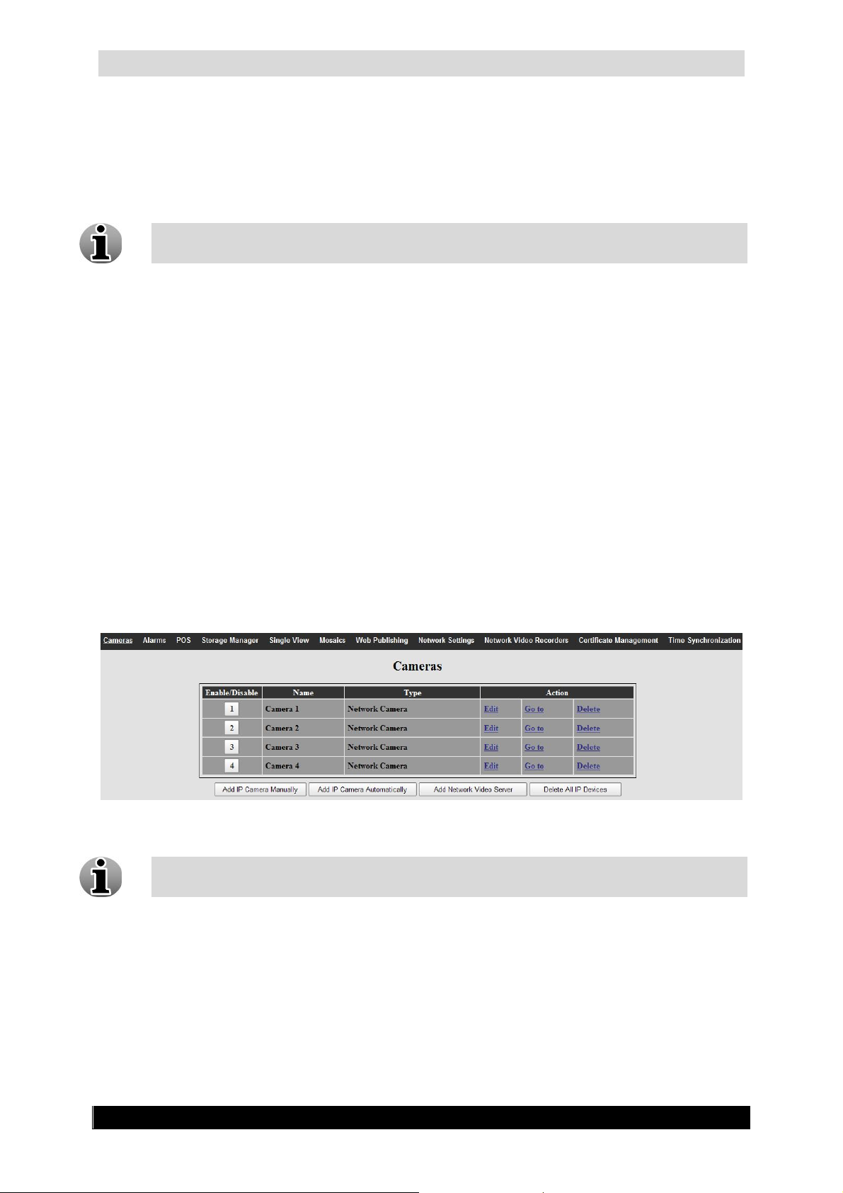
The Cameras overview screen is automatically displayed, when entering Settings menu.
The WebCCTV supports both Analogue and Network cameras.
Analogue cameras can also be added and edited through a Network Video Server.
To add a Network camera click the Add IP Camera and follow the on-screen instructions
in the Camera Wizard (See 3.3.1.1 Camera Wizard).
To add a Network Video Server click the Add Network Video Server and follow the onscreen instructions in the NVS Wizard (See 3.3.1.2 Network Video Server Wizard).
To change Camera or Network Video Server settings, click the Edit button to enter the
Camera or Network Video Server Wizard which will guide you through the setting process
for that camera or network video server.
To directly access a Network camera or a Network Video Server, click the Go to button.
This function is available for IP-cameras only.
To delete a Network camera, click the Delete button.
To delete a Network Video Server, click the Delete button.
To delete all IP devices, click the Delete All IP Devices button.
Cameras Screen
To disable or enable a camera click its number. The button will become red when the
camera is disabled in the system.
Version 4.9 Series
Page 30

WebCCTV User Manual 30
o
3.3.1.1 Camera Search Wizard
To enter the Auto-configuration wizard, click the Add IP Camera Automatically button.
The Camera Search screen will be opened and will start searching automatically for cameras
in the Local Area Network (LAN).
Following vendors are supported by Camera Search:
Approtech:
o All models supported. (See supported camera list for all models)
Arecont:
o All models supported. (See supported camera list for all models)
Axis:
o AXIS 2XX video products with firmware versions 4.03/4.10 or higher
o Exceptions: AXIS 205 / 230 / 250S / 262 / 292.
o AXIS 1XXX, 3XXX, PXXXX and QXXXX series
IQEye:
o IQEye Sentinel Series
Panasonic:
Zavio:
o IQEye Alliance Series
o IQEye 700/750 Series
o IQEye 500 Series
o IQEye HD1080p Series
o BL-C1 / 10 / 20 / 30 / 101 / 111 / 121 / 131 / 140 / 160 / 210 / 230
o BB-HCM311 / 331 / 371 / 381 / 403 / 511 / 515 / 527 / 531 / 547 / 580 / 581 / 701 /
705 / 715 / 735
o BB-HCE481
All models supported. (See supported camera list for all models)
Cameras Search Screen
To add a camera, specify the name you want to give to the camera (Optional), select the
check box next to the camera and click the Add selected cameras button.
You don’t have to wait till the search has stopped to start adding cameras.
The Camera Auto Configuration Wizard will open and has the following tabs:
IP Address
Authentication
Version 4.9 Series
Page 31

WebCCTV User Manual 31
3.3.1.1.1 IP Address
In this screen you configure the Starting IP Address for the cameras you are adding.
Depending on the network settings of your computer (Subnet Mask), fields will be
disabled in order to enforce that the camera is added in the correct network.
Each selected camera will be assigned a consecutive IP address, starting with the
address which will be prompted. Only free addresses will be used. If the camera
already has an IP address in the correct subnet, it will not be changed.
IP Address Screen
Click Next to enter the next Camera Search screen.
3.3.1.1.2 Authentication
This screen allows you to enter the login credentials for your cameras. Select the radio button
which is applicable for your cameras. There are two possibilities:
Cameras with factory default settings – The cameras have factory default settings.
Enter a password and confirm it. This password will be assigned to the Administrator
account of the cameras.
Cameras are pre-configured – The cameras have been configured in the past and are
located in the correct network. Enter the user name and password that were used at
that time. If preferred, you can assign a new password in the new password field,
otherwise leave this field empty.
Quadrox recommends using one password for all the cameras for your convenience.
This might however affect security. If the password leaks, all cameras are
compromised. If you want a fully secured video network, manually assign different
passwords to every camera after completing this configuration.
Version 4.9 Series
Page 32

WebCCTV User Manual 32
Authentication Screen
Click Finish to add the cameras. A Camera Adding Result screen will open with the results
and the server will restart automatically if necessary. To start a new search, click the New
Camera Search button.
Camera Adding Result Screen
Click Cancel to go back to the Camera Search screen.
You can always add cameras manually by clicking the Add IP Camera button in the
Cameras Screen.
Version 4.9 Series
Page 33

WebCCTV User Manual 33
3.3.1.2 Camera Wizard
To enter the Camera Wizard click the Edit or the Add IP Camera button in the Cameras
Screen. The Camera Wizard can consist of eight tabs with easy to follow instructions. Read
this chapter to learn all about camera settings.
The following Camera Wizard tabs are described in this chapter:
Name & Type
Connection
Live view
Recordings
Activity
PTZ
Virtual Patrol
Users
By default, some of the settings are already selected. It is advisable to keep these
settings to assure the best performance.
Depending on the camera type (network or analogue) and camera model, some tabs
may not be present or may be disabled.
During the configuration, you may be asked to restart the server. This must be done
first before finishing the configuration to assure the proper working of the WebCCTV
server.
3.3.1.2.1 Name & Type
In this screen, you define the camera name, type and model of the camera.
Once the camera is added, you cannot change its type.
Name & Type (Network camera) Screen
Click Next to enter each camera and go to the next Camera Wizard screen.
Version 4.9 Series
Page 34

WebCCTV User Manual 34
3.3.1.2.2 Connection
This tab is only available for network cameras. If you are adding an analogue camera,
this screen will not appear.
This screen allows you to define the parameters needed for a network camera connection:
Camera IP address or DNS name
Port
User name
Password
Delivery mode
Multicast IP-Address Port
To obtain these parameters, contact your system administrator or read the user manual
of the camera itself.
Use camera Administrator credentials in order to get all WebCCTV functionality.
A DNS name is a meaningful and easy-to-remember "handle" for an Internet address
or IP address.
Connection (Network camera) Screen
The delivery mode parameter is only available when the network camera supports MPEG
streaming:
Unicast – normal connection type of a camera. It is simple in organization and
efficient when one connected client uses the camera. So if WebCCTV is the only user
of the camera, please use this type.
Version 4.9 Series
Page 35

WebCCTV User Manual 35
Multicast – this connection type is efficient when multiple applications use the
cameras. This approach decreases the bandwidth usage. MPEG cameras allow sending
the images to multicast IP addresses. These addresses are reserved in the IP protocol
for multicast information distribution. To program a camera to send the images to a
multicast address, you have to configure it in the camera’s native software software.
Specify the IP address on the Connection Screen of the camera wizard.
Multicast IP addresses are in the range 224.0.0.0 through 239.255.255.255.
Click Next to enter the next Camera Wizard screen.
3.3.1.2.3 Live View
The Live View tab will appear differently depending on whether you are viewing Analogue or
IP cameras.
The following parameters can be set for an analogue camera:
Image resolution – as a rule of thumb, the higher the quality of the image (higher
image resolution), the lower the frame rate you will have.
Differential transmission – when differential transmission is enabled, only the
differences between subsequent images are sent over the network. This feature
drastically decreases the amount of transmitted video-data and is especially designed
to be used when viewing camera images over the Internet.
Live View (Analogue camera) Screen
Version 4.9 Series
Page 36

WebCCTV User Manual 36
The following parameters can be set for a network camera:
Format – gives an opportunity to choose between commonly used Compression
technologies or indicates the compression technology that is used for a specific camera
type.
Image resolution – a higher resolution gives a better quality image. A higher image
resolution will lead to a lower frame rate.
Live View (Network camera) Screen
Click Next to enter the next Camera Wizard screen.
3.3.1.2.4 Recordings
The available parameters for recordings are the same for analogue and network cameras:
Record this camera – the camera will be recorded if the box is checked.
Format – gives the option to choose between commonly used compressions
technologies or indicates the compression technology that is used for a specific camera
type.
Image resolution – a higher resolution gives a better quality image. A higher image
resolution will lead to a lower frame rate.
Frame rate – possible frame rates depend on the chosen image resolution.
Volume – the storage volume on which the camera is recorded. You can change the
volume for each camera (see 3.3.4 Storage Manager)
Version 4.9 Series
Page 37

WebCCTV User Manual 37
Recordings (Analogue and Network camera) Screen
Click Next to enter the next Camera Wizard screen.
Version 4.9 Series
Page 38

WebCCTV User Manual 38
3.3.1.2.5 Activity
By enabling activity detection, only images where movement is above a certain threshold will
be recorded. This significantly increases the ability to store more video footage. If you want
to record at all time, uncheck the Record only activity checkbox.
If you use activity detection, you can always calculate activity on the server, but if the camera
allows, you can configure the server to calculate activity on the camera instead of on the
server:
Server – When activity is calculated on the server, this will result in excellent
recordings but introduces a higher load on the server. Furthermore you’re able to use
the masking feature. By using the Masking feature, only activity in a specified
area(s) will be recorded. This significantly increases the ability to store video footage.
When adding a network camera, the Masking and Activity functionality is only
available after a server restart. This will be requested automatically by a notification.
The current activity level is represented by the green line on the control panel below
the video. To adjust the activity detection threshold, move the slider on the right side
of the control panel up and down to shift the red line. All the video activity that stays
above the red line will be recorded.
Activity on Server (Analogue and Network camera) Screen
Masking makes it possible to disable the recording of activity in so called ‘curtain
areas’. ‘Curtain areas’ contain constant movement classified as not important for
surveillance (e.g. moving trees in the wind, ceiling fan etc.).
The green grid, shown on the masking screen, divides the image into masking cells.
Click on a cell and the activity detection in this cell will be disabled. Once disabled, a
masking cell turns green. This means that activity occurring in this cell will not
trigger recording.
Version 4.9 Series
Page 39

WebCCTV User Manual 39
When you access the Activity screen for the first time on a client PC, it may be that
the green masking grid doesn’t appear. In order to be able to draw the grid, the video
card of the client PC has to have at least 16 MB of internal video memory and
DirectX accelerations fully enabled. This can be done as follows:
1. Exit the camera wizard by clicking Finish or Cancel.
2. Go to Start/Settings/Control Panel.
3. Click on Display/ Settings/Advanced/Troubleshoot.
4. Set Hardware acceleration on full.
Troubleshoot Screen
Click OK and return to the Activity Screen in the Camera Wizard. The masking grid
should be visible on your screen now.
The masking functionality does not depend on whether you can visualize it on a
particular client PC or not. It is possible to set up masking on one client PC and use
another client PC which is not able to show masking. The masking will stay applied.
To (un)mask the desired area, follow the steps below:
1. Click on the cell you wish to (un)mask.
2. Check the Mask or Unmask button depending on whether you want to mask or
unmask.
3. Click the Apply mask button to activate the selection.
To mask multiple cells, left-click one cell and drag the cursor over the cells you
would like to mask and release your mouse.
Click on the question mark icon in the right hand corner of the masking screen
to access on-screen masking instructions.
Click Next to enter the next Camera Wizard screen.
Camera – When activity is calculated on the camera, this will result in acceptable
recordings and a lower load on the server. The masking feature is disabled and has to
be done on the camera. By default nothing has to be configured on the camera,
nevertheless some models require configuration on the camera itself. See Appendix C
for more information.
Version 4.9 Series
Page 40

WebCCTV User Manual 40
Activity calculated on camera is supported for most models of the following brands:
ACTi, Axis, Ernitec, IQEye.
If activity is recorded or not depends on the camera activity detection algorithm. If
you notice problems with recordings, please contact the camera manufacturer for
support.
Activity on Camera (Network camera) Screen
Click Next to enter the next Camera Wizard screen.
3.3.1.2.6 PTZ
This tab is present for both analogue and network PTZ cameras, however only analogue PTZ
cameras can be configured
PTZ stands for Pan Tilt Zoom, or a "movable" camera. To enable the PTZ camera
settings, select the PTZ camera checkbox.
PTZ camera – check this if your camera is a PTZ camera
PTZ control protocol – select the brand of the PTZ camera
Extended PTZ – Some protocols have extended PTZ features; e.g. Pelco. By
checking this, these extended features will be made available.
Communication port – serial communication port used for PTZ communication.
Camera unique number – most PTZ cameras require a unique serial number to be
referred by.
Click Next to enter the next Camera Wizard screen.
Version 4.9 Series
Page 41

WebCCTV User Manual 41
3.3.1.2.7 Virtual Patrol
The Virtual Patrol screen allows you to configure a PTZ camera in several ways:
Use Home preset – this functionality prevents the misplacement of the camera and
ensures proper recordings after monitoring. If the Home Preset is enabled, the first
preset position becomes automatically the Home status and looks like in the Live
view. When a user moves the PTZ camera, by manual manipulation or using preset
positions, the camera will return to its Home Preset after the assigned Recovery Time
has elapsed. By default this time is 300 seconds.
Use Virtual Patrol – select one of the Virtual Patrols you previously created.
Manual PTZ Control – check this radio button if you don’t use either the Home
Preset or the Virtual Patrol functionality.
Virtual Patrol (Analogue and network camera) Screen
Only specially designed cameras designated by the manufacturer as "Continuous
movement use", "Continuous duty cycle" or "24h duty cycle" can effectively utilize
the Virtual Patrol feature. Using consumer-grade cameras with Virtual Patrol may
cause premature failure and may invalidate the cameras warranty. We strongly advise
customers to check the camera specifications before using the Virtual Patrol feature
and strongly advise setting the virtual patrol sequence time to a minimum of 120
seconds for those cameras.
You can create multiple Virtual Patrols with different settings. Click the Add Virtual Patrol
button to add a new Virtual Patrol.
To change or create the Virtual Patrol settings, click the Edit link.
Version 4.9 Series
Page 42

WebCCTV User Manual 42
Virtual Patrol Configuring Screen
1. Specify a Name for the Virtual Patrol
2. Choose one of the available Presets from the drop-down list and click Add Preset
button.
3. Specify the Sequence time for every Preset. This is the time after which the camera is
switched to the next defined preset in the queue.
4. If necessary, use the Sort buttons to change the position of a Preset in the Virtual
Patrol sequence.
5. Click Apply button.
You may delete any Preset from the Virtual Patrol sequence by clicking the Delete link.
Due to some technology designs of Panasonic cameras, it is recommended to use no
more than 2-3 Panasonic cameras with virtual patrol configured at the same time,
since this can cause server overloading.
Each time a user takes control over the PTZ camera manually (via the PTZ Camera
Control Panel), the automatic Virtual Patrol is interrupted. Once the user stops his
manual control, the WebCCTV resumes the Virtual Patrol after 30 seconds.
Click Next to enter the next Camera Wizard screen.
Version 4.9 Series
Page 43

WebCCTV User Manual 43
3.3.1.2.8 Users
Select which users have access to the selected camera.
The Users functionality is only available after you have added the camera, and
restarted the server. Follow the notification that will automatically be shown.
Users with Administrator rights have access to all cameras. Users with restricted
rights can be denied access to certain cameras.
Users (Analogue and network camera) Screen
3.3.1.2.9 Audio
The audio tab is only available for network cameras that support audio. For more
information about audio support, go to 4.2.1.10 Audio.
This screen allows you to define the audio parameters for a network camera:
Live audio – This enables live listen-in audio.
External IP-address – Configure this if you want to enable remote live listen-in
audio.
Audio (Network camera) Screen
Version 4.9 Series
Page 44

WebCCTV User Manual 44
3.3.1.3 Network Video Server Wizard
In this manual, we will refer to a Network Video Server as NVS.
To enter the Network Video Server Wizard, click the Edit device or Add Network Video
Server link/button in the Cameras screen. The Network Video Server Wizard consists of
three tabs with easy to follow instructions.
The following Network Video Server Wizard tabs are described in this chapter:
Name & Type
Connection
Video Settings
If you need to change camera settings from cameras that are connected to the NVS, click the
Edit link of the camera in the cameras screen which will display the Network Video Server
Cameras Wizard. The Network Video Server Camera Wizard consists of six tabs with easy
to follow instructions.
The following Network Video Server Camera Wizard tabs are described in this chapter:
Name
Recordings
Activity
PTZ
Virtual Patrol
Users
You need to install the Quadrox Codecs Pack for proper NVS usage.
The NVS Wizard displays settings which are common for all cameras connected to
the NVS. In the NVS Camera Wizard you are able to adjust the specific settings for
an individual camera connected to the NVS.
By default, some of the settings are already selected. It is recommended that you keep
these settings to ensure the best performance.
Cameras Screen
Version 4.9 Series
Page 45

WebCCTV User Manual 45
3.3.1.3.1 Name & Type
In this tab, you can adjust the NVS name, type and model. It’s a part of the Network Video
Server Wizard.
Choose a descriptive name for each NVS for easy future reference.
Name & Type (Network Video Server) Screen
Click Next to enter the next NVS Wizard screen.
3.3.1.3.2 Connection
This tab allows you to define the parameters needed for the NVS connection. It’s a part of the
Network Video Server Wizard:
NVS IP address
User name
Password
The Default Admin ID for the NVS400 series is ‘admin’ and the default Admin
password is ‘pass’. For the NVS1000/2000/4000 series the Admin ID becomes ‘root’
and the default Admin password is ‘pass’.
Connection (Network Video Server) Screen
Click Next to enter the next NVS Wizard screen.
Version 4.9 Series
Page 46

WebCCTV User Manual 46
3.3.1.3.3 Video Settings
This tab is a part of the Network Video Server Wizard and allows configuring following
settings:
Video format – selection of the video standards format in which images are
transmitted from the cameras. PAL video standard is used in Europe, NTSC video
standard is used in the USA.
Image resolution – a higher resolution gives a better quality image. A higher image
resolution will lead to a lower frame rate.
Frame rate – possible frame rates depend on the chosen image resolution.
Volume – storage volume on which the camera is recorded. You can change the
volume for each camera (see 3.3.4 Storage Manager)
Settings you are adjusting in this screen are applied to all NVS cameras for live view
and recordings.
Video Settings (Network Video Server) Screen
Complete the procedure by clicking Finish button and Restart the WebCCTV server.
3.3.1.3.4 Name
This tab is a part of the Network Video Server Camera Wizard. You can assign a name to
the camera in this screen.
Name (Network Video Server) Screen
Click Next to enter the next NVS Camera Wizard screen.
Version 4.9 Series
Page 47

WebCCTV User Manual 47
3.3.1.3.5 Recordings
This tab is a part of the Network Video Server Camera Wizard. The following parameters
can be configured:
Record this camera – the camera will be recorded if the box is checked.
Volume – storage volume on which the camera is recorded. You can change the
volume for each camera (see 3.3.4 Storage Manager)
Recordings (Network Video Server) Screen
Click Next to enter the next NVS Camera Wizard screen.
3.3.1.3.6 Activity
This tab is a part of the Network Video Server Camera Wizard. The following parameters
can be configured:
When adding a NVS, the Masking and Activity functionality is only available after
server restart. This will be automatically requested by a notification.
Activity Detection – by enabling Activity Detection, only images where movement is
above a certain threshold will be recorded. This increases the ability to store more
video footage significantly. If you want to record all the time, uncheck the Record
only activity checkbox.
Activity (Network Video Server) Screen
Version 4.9 Series
Page 48

WebCCTV User Manual 48
The current activity level is represented by the green line on the control panel below
the video. To adjust the activity detection threshold, move the slider on the right side
of the control panel up and down to shift the red line. All the video activity that stays
above the red line will be recorded.
Masking – by using the masking feature, only activity in a specified area(s) will be
recorded. This increases the ability to store more video footage significantly.
Calculate activity on – Each method of activity detection processing has advantages
and disadvantages. Activity detection processing on the WebCCTV server allows
detecting the activity using the best accuracy, but consumes more CPU resources.
Activity detection processing on WebCCTV NVS consumes fewer CPU resources, but
operates inaccurately in low light conditions.
Masking makes it possible to disable the recording of activity in so called ‘curtain
areas’. ‘Curtain areas’ contain constant movement classified as not important for
surveillance (e.g. moving trees in the wind, busy parts of the road etc.).
The green grid, shown on the masking screen, divides the image into masking cells.
Click on a cell and the activity detection in this cell will be disabled. Once disabled, a
masking cell turns green. This means that activity occurring in this cell will not
trigger recording.
When you access the Activity screen for the first time on a client PC, it may be that
the green masking grid doesn’t appear. In order to be able to draw the grid, the video
card of the client PC has to have at least 16 MB of internal video memory and
DirectX accelerations fully enabled. This can be done as follows:
1. Exit the camera wizard by clicking Finish or Cancel.
2. Go to Start/Settings/Control Panel.
3. Click on Display/ Settings/Advanced/Troubleshoot.
4. Set Hardware acceleration on full.
Troubleshoot Screen
Click OK and return to the Activity Screen in the Camera Wizard. The masking grid
should be visible on your screen now.
Version 4.9 Series
Page 49

WebCCTV User Manual 49
The masking functionality does not depend on whether you can visualize it on a
particular client PC or not. It is possible to set up masking on one client PC and use
another client PC which is not able to show masking. The masking will stay applied.
To (un)mask the desired area, follow the steps below:
1. Click on the cell you wish to (un)mask.
2. Check the Mask or Unmask button depending on whether you want to mask or
unmask.
3. Click the Apply mask button to activate the selection.
To mask multiple cells, left-click one cell and drag the cursor over the cells you
would like to mask and release your mouse.
Click on the question mark icon in the right hand corner of the masking screen
to access on-screen masking instructions.
Click Next to enter the next NVS Camera Wizard screen.
3.3.1.3.7 PTZ
This tab is a part of the Network Video Server Camera Wizard.
PTZ stands for Pan Tilt Zoom or movable camera. To enable PTZ camera settings,
select the PTZ camera check box first.
PTZ camera – select this if your camera is a PTZ camera.
PTZ control protocol – select the brand of the PTZ camera.
Extended PTZ – Some protocols have extended PTZ features, e.g. Pelco. By
checking this, the features will be made available.
Camera unique number – most PTZ cameras require a unique serial number to be
referred by.
PTZ (Network Video Server) Screen
Click Next to enter the next NVS Camera Wizard screen.
Version 4.9 Series
Page 50

WebCCTV User Manual 50
3.3.1.3.8 Virtual Patrol
This tab is a part of the Network Video Server Camera Wizard. The Virtual Patrol screen
allows you to configure a PTZ camera in several ways:
Use Home preset – this functionality prevents the misplacement of the camera and
ensures proper recordings after monitoring. If the Home Preset is enabled, the first
preset position becomes automatically the Home status and looks like in the Live
view. When a user moves the PTZ camera, by manual manipulation or using preset
positions, the camera will return to its Home Preset after the assigned Recovery Time
has elapsed. By default this time is 300 seconds.
Use Virtual Patrol – select one of the Virtual Patrol you previously created.
Manual PTZ Control – check this radio button if you don’t use either the Home
Preset or the Virtual Patrol functionality.
Virtual Patrol (Network Video Server) Screen
Only specially designed cameras designated by the manufacturer as "Continuous
movement use", "Continuous duty cycle" or "24h duty cycle" can effectively utilize
the Virtual Patrol feature. Using consumer-grade cameras with Virtual Patrol may
cause premature failure and may invalidate the cameras warranty. We strongly advise
customers to check the camera specifications before using the Virtual Patrol feature
and strongly advise to set the virtual patrol sequence time to a minimum of 120
seconds for those cameras.
You can create multiple Virtual Patrols with different settings. Click the Add Virtual Patrol
button to add a new Virtual Patrol.
To change or create the Virtual Patrol settings, click the Edit link.
Version 4.9 Series
Page 51

WebCCTV User Manual 51
Virtual Patrol Configuring Screen
1. Specify a Name for the Virtual Patrol
2. Choose one of the available Presets from the drop-down list and click Add Preset
button.
3. Specify the Sequence time for each Preset. This is the time after which the camera
switches to the next defined preset in the queue.
4. If necessary, use the Sort buttons to change the position of a Preset in the Virtual
Patrol sequence.
5. Click Apply button.
You may delete any Preset from the Virtual Patrol sequence by clicking the Delete link.
Due to some technology designs of Panasonic cameras it is recommended you use no
more than 2-3 Panasonic cameras with virtual patrol configured at the same time,
since this can cause server overloading.
Each time a user takes control over the PTZ camera manually (via the PTZ Camera
Control Panel), the automatic Virtual Patrol is interrupted. Once the user stops his
manual control, the WebCCTV resumes the Virtual Patrol after 30 seconds.
Click Next to enter the next NVS Camera Wizard screen.
3.3.1.3.9 Users
Select which users have access to the selected camera.
The Users functionality is only available after server restart when adding a new NVS.
Follow the notification that automatically will be shown.
Users with Administrator rights have access to all the cameras. Users with restricted
rights can be denied access to certain cameras.
Users (Network Video Server) Screen
Version 4.9 Series
Page 52

WebCCTV User Manual 52
3.3.2 Alarms
The Alarms chapter covers the handling and configuration of incoming alarms, alarm
reactions and how to configure the actions linked to these incoming alarm events.
Input alarms can be generated through a physical alarm-input concentrator (screw-block to
attach physical wires) attached on the back of the WebCCTV machine (together with a Picolo
card), or through a PMD I/O Device (screw-block to attach physical wires) attached to the
WebCCTV NVR via a USB cable.
The WebCCTV Alarm Component supports the OPC protocol; hence you are able to connect
any OPC A&E compliant alarm server and OPC A&E compliant client as well to the
WebCCTV Alarm Component. The origin of an alarm input can be an external infrared
sensor, a reed contact, etc.
By default you get the alarms menu when clicking Alarms in the Settings menu. This menu
allows you to Add PMD I/O Device, Add Alarm Device and access the Alarms
Configuration Wizard by clicking Edit or Edit Device.
This chapter covers the following topics:
Picolo I/O Proxy Device (Adding and Configuring)
PMD I/O Device (Adding and Configuring)
Generic Alarm Driver
RedLight Driver
Alarms Configuration Wizard
Alarms Screen
Version 4.9 Series
Page 53

WebCCTV User Manual 53
3.3.2.1 Picolo I/O Proxy
When you start the WebCCTV server, it detects your Picolo I/O video capturing card and
automatically sets it up.
WebCCTV’s manufactured after 2007 may be a different type of capture card on
which I/O is not supported. Use a PMD I/O Device in this case.
Alarms (Picolo I/O Proxy) Screen
Click the Edit Device link to open the I/O Device Configuration Wizard which allows for
the configuration of the Picolo I/O Proxy.
3.3.2.1.1 Name
This screen doesn’t allow you to configure any parameter. It contains two fields:
Device type – general information about the type of I/O Device connected.
Serial Number – serial number of your I/O Device.
Name (Picolo I/O Proxy) Screen
Click Next to enter the next I/O Device Configuration Wizard Screen.
Version 4.9 Series
Page 54

WebCCTV User Manual 54
3.3.2.1.2 Configuration
This screen allows you to configure your I/O Device lines as inputs or outputs for the alarm
signals. If you don’t need all of the line(s) you can disable the unused lines.
The screen contains the picture of the I/O Device connector with 13 drop-down lists around it
which correspond to 13 lines of the I/O Device. Each drop-down list has 3 options available:
I, O and X.
Configuration (Picolo I/O Proxy) Screen
Value Description
I
O
X
Click Next to enter the next I/O Device Configuration Wizard Screen.
Configure line as input. This line receives an alarm signal from an
external device.
Configure line as output. This line sends a control signal to the
external device.
Disable the line. This line neither receives, nor sends controls signals.
3.3.2.1.3 Outputs
This screen allows you to assign names to the lines you have configured as outputs.
Outputs (Picolo I/O Proxy) Screen
If you didn’t configure any line as an output, the following message will be shown: “No
outputs are currently configured for this device”. Consequently no configuration will be
available on this page.
Click the Finish button to apply the configuration.
Version 4.9 Series
Page 55

WebCCTV User Manual 55
3.3.2.2 PMD I/O Device
The PMD I/O device has to be added manually. To do so, follow the steps below:
1. Attach the PMD I/O Device to one of the USB ports of your WebCCTV.
PMD I/O Device supports USB 2.0.
2. Click Add PMD I/O Device button.
Alarms (PMD I/O Device) Screen
The PMD I/O Device Configuration Wizard will be opened for configuration.
3.3.2.2.1 Name
This screen shows basic information about the I/O Device. It contains two fields:
Device type – general information about the type of I/O Device connected.
Serial Number – enter the serial number of your I/O Device in this field.
To obtain the serial number of your PMD I/O Device, refer to PMD I/O Device
documentation or use the special tool that is located in the Support folder to set a new
serial number. (see 3.3.2.2.5 PMD I/O Serial Number)
Name (PMD I/O Device) Screen
Click Next to enter the next I/O Device Configuration Wizard Screen.
Version 4.9 Series
Page 56

WebCCTV User Manual 56
3.3.2.2.2 Configuration
This screen allows you to configure your I/O Device lines as inputs or outputs for the alarm
signals.
Configuration (PMD I/O Device) Screen
When the PMD I/O device is disconnected from the USB port and the server is
restarting, the PMD device disappears from I/O Devices list. After being reconnected
and subsequently restarting the server, it appears again.
The PMD I/O device has 3 ports and each port has 8 lines, however one port is divided in two
parts, where every subpart has 4 lines. This makes 24 lines in total. Compared to the Picolo
I/O card, where every line can be configured separately, you need to configure a whole port as
an input or output for the PMD I/O device. There are 4 drop-down lists and each of them
corresponds to a certain port.
Value Description
I
O
Click Finish button.
Configure line as input. This line receives an alarm signal from an
external device.
Configure line as output. This line sends a control signal to the
external device.
If you entered a correct PMD I/O Device serial number you should see the following screen:
Version 4.9 Series
Page 57

WebCCTV User Manual 57
Outputs
Alarms (PMD I/O Device Added) Screen
Click Edit Device link. Go to the Outputs tab.
3.3.2.2.3 Outputs
This screen allows you to assign names to the lines you have configured as outputs.
The
Wizard when you are adding the PMD I/O Device. It becomes available after you add
the device and click Edit Device link in the Alarms menu.
tab is not available in the WebCCTV PMD I/O Device Configuration
Outputs (PMD I/O Device) Screen
Click the Finish button to apply the configuration.
Version 4.9 Series
Page 58

WebCCTV User Manual 58
3.3.2.2.4 Delete PMD I/O Device
If you want to delete your PMD I/O Device, execute the following steps:
1. While being in Alarms Menu, click the Delete Device link.
Alarms (Deleting PMD I/O Device) Screen
2. Click OK in the pop-up window.
Confirmation (Deleting PMD I/O Device) Screen
3.3.2.2.5 PMD I/O serial number
To assign the serial number to a PMD I/O Device, follow the steps below:
1. Connect your PMD I/O Device to the computer.
2. Go to C:\Program Files\Quadrox\, find pmdserialnumber.exe and click on it.
3. A command prompt will appear.
Assigning PMD I/O Serial Number Screen 1
Version 4.9 Series
Page 59

WebCCTV User Manual 59
4. Specify Y and click Enter button.
5. Please enter the new serial number message will appear on the screen, specify new
serial number. Click Enter.
Assigning PMD I/O Serial Number Screen 2
6. As prompted, press any key to finish assigning the PMD I/O Device serial number.
3.3.2.3 Generic Alarm Driver
The Generic Alarm Driver makes it possible to generate alarms without needing a hardware
device. Generating alarms is done by using the SDK (Software Development Kit). For more
information about how to utilize the SDK Kit, contact SDK@quadrox.be.
To add the Generic Alarm Driver, click Add Alarm Device button.
Alarms Screen
The Alarm Configuration Wizard will be opened for configuration.
3.3.2.3.1 Name
This tab allows you to specify the Device Name.
Name (Generic Alarm Driver) Screen
Click Next to enter the next Alarm Configuration Wizard Screen.
Version 4.9 Series
Page 60

WebCCTV User Manual 60
Edit Device
3.3.2.3.2 Protocol
In this tab, the protocol has to be selected
Select Generic Alarm Driver in the drop-down list.
Protocol (Generic Alarm Driver) Screen
Click Finish button.
Depending on the drivers you installed together with the Alarm Component, it’s
possible some values are not present in the drop-down list.
If you entered the Alarm Configuration Wizard by clicking the
the Alarms Screen, you can’t change the protocol anymore, but can only see which
protocol has been selected.
link in
3.3.2.3.3 Connection
This tab is not available for the Generic Alarm Driver Device. You don’t have to configure it.
3.3.2.4 RedLight Alarm Driver
The RedLight Alarm Driver makes it possible to receive alarms for Red Light infractions.
This driver may and can only be used in cooperation with Quadrox N.V. For more
information, contact sales@quadrox.be.
You need extra add-on software to be able to receive alarms.
To add the RedLight Alarm Driver, click Add Alarm Device button.
Alarms Screen
The Alarm Configuration Wizard will be opened for configuration.
Version 4.9 Series
Page 61

WebCCTV User Manual 61
Edit Device
3.3.2.4.1 Name
This tab allows you to specify the Device Name.
Name (RedLight Alarm Driver) Screen
Click Next to enter the next Alarm Configuration Wizard Screen.
3.3.2.4.2 Protocol
In this tab, the protocol has to be selected
Select RedLight Driver in the drop-down list.
Protocol (RedLight Alarm Driver) Screen
Click Next to enter the next Alarm Configuration Wizard Screen.
Depending on the drivers you installed together with the Alarm Component, it’s
possible some values are not present in the drop-down list.
If you entered the Alarm Configuration Wizard by clicking the
the Alarms Screen, you can’t change the protocol anymore, but can only see which
protocol has been selected.
3.3.2.4.3 Connection
This tab allows for the configuration of the following settings:
Dispatcher IP – IP address of the sender of the alarm events.
Dispatcher Port – port used by dispatcher to send alarm events.
Client IP – IP address of the client which accepts the alarm events. Basically this
should be the WebCCTV server IP Address.
link in
Client Port – port used by client to receive alarm events.
Client Name – unique name which identifies the client machine.
Version 4.9 Series
Page 62

WebCCTV User Manual 62
Connection (RedLight Alarm Driver) Screen
3.3.2.5 Alarm Configuration Wizard
To enter the Alarm Configuration Wizard in order to configure the alarms itself, click one of
the Edit links in the Alarms Menu. The Alarm Configuration Wizard consists of eight tabs
with easy to follow instructions. Read this chapter to learn all about the alarms configuration.
The following Alarm Configuration Wizard tabs are described in this chapter:
Name
PTZ
Recordings
FTP
Outputs
Notification
Mail
SMS
By default, some of the settings are already selected. It is recommended you keep
these settings to ensure the best performance.
When configuring a hybrid WebCCTV, you are able to use 13 Input/Output lines (for
Q16 model – 26 I/O lines if 2 Picolo Tetra cards are used) by means of Picolo I/O
Proxy. A PMD I/O Device gives you the ability to use 24 Input/Output lines.
WebCCTV’s manufactured after 2007 may be a different type of capture card on
which I/O is not supported. Use a PMD I/O Device in this case.
A PMD I/O Device or Picolo I/O Proxy Device has a fixed amount of alarms
available. For the RedLight and Generic Device, you can add as many alarms as you
wish by clicking the Add Alarm link in the Alarms Screen.
3.3.2.5.1 Name
In this tab, you can define the alarm name; can see the device and pin to which the alarm is
associated.
Choose a descriptive name for each alarm for future reference.
Version 4.9 Series
Page 63

WebCCTV User Manual 63
Name (Alarm – PMD I/O Device) Screen
Name (Alarm – Generic / RedLight Alarm Driver) Screen
Click Next to enter the next Alarm Configuration Wizard Screen.
3.3.2.5.2 PTZ
You can choose the PTZ reaction for the incoming alarm, meaning if an alarm is triggered the
specified camera will turn to the selected camera preset position. To configure this feature,
follow the steps below:
1. Select the camera from the drop-down list.
2. Select the preferred preset position.
3. Click the Add camera button.
You are able to change the preset position for the camera only after it has been added.
Settings presets is explained in the Video Browser manual.
If there are no PTZ camera configured in the system, the message “No PTZ cameras
are available in the system” will be shown.
PTZ (Alarm) Screen
To delete the camera, click Delete.
Click Next to enter the next Alarm Configuration Wizard Screen.
Version 4.9 Series
Page 64

WebCCTV User Manual 64
3.3.2.5.3 Recordings
In this tab you are able to do the following:
Add or delete cameras to record when an alarm occurs.
Multiple recordings can be assigned to one alarm. This way, an incident can be
monitored from different cameras and angles.
Set the recording time before and after an alarm has occurred. This is also called the
pre and post alarm recording interval.
An alarm movie is labelled recorded footage from a camera you attached to the alarm,
i.e. when an alarm comes in, the specific period of time recorded from a specified
camera is labelled and saved. Once the recording is complete, it appears as an alarm
movie. If there aren’t any recordings (i.e. when there is no activity) for the period
when the alarm occurs, you won’t have an alarm movie. You can set a camera to
record all the time via the Camera Configuration Wizard.
To add the camera to be recorded when an alarm is triggered, follow the steps below:
1. Select the camera from the drop-down list.
2. Select the pre and post alarm label interval for each camera.
3. Click the Add camera button.
Recordings (Alarm) Screen
To delete a camera, click Delete.
Click Next to enter the next Alarm Configuration Wizard Screen.
Version 4.9 Series
Page 65

WebCCTV User Manual 65
3.3.2.5.4 FTP
The FTP upload function enables automatic uploading of the movies and images, which were
created based on an incoming alarm, onto a remote FTP server or to a local folder for further
revision and storing. To configure FTP uploading, see 3.3.7.2 FTP Parameters.
An alarm image is a snapshot captured at the moment the alarm is triggered.
To use this feature, select the corresponding checkbox.
FTP (Alarm) Screen
Click Next to enter the next Alarm Configuration Wizard Screen.
3.3.2.5.5 Outputs
This tab allows you to configure which outputs will send the signals to the external devices
when an alarm is triggered.
The output tab is only available if some lines of the I/O device are set as output.
To configure outputs follow the steps below:
1. Select the output from the corresponding drop – down list.
2. Select the state to which the output will switch when an alarm is triggered.
By default the output is in Low State. This means that the voltage on the
corresponding pin is 0 V. When an alarm is triggered, the output switches to the High
State which corresponds to the voltage of 5 V.
3. Choose when the output will return to its previous state. There are two variants:
Output returns to its previous state in a time span you indicate.
Output returns to its previous state on the deactivation of the triggered alarm.
4. Click Add Output button.
Version 4.9 Series
Page 66

WebCCTV User Manual 66
Outputs (Alarm) Screen
Click Next to enter the next Alarm Configuration Wizard Screen.
3.3.2.5.6 Notification
This tab allows you to configure the sound notification for an incoming alarm. At the same
time, it’s possible to automatically switch to live view for an assigned camera.
To use the sound notification, speakers should be connected to WebCCTV server.
To get the sound notification signal when an alarm is triggered, select the Play sound
checkbox.
To configure switching to Live View on a specific camera, follow the steps below:
1. Select Switch to Live view from camera checkbox.
2. Choose the desired camera from the drop-down list.
Notification (Alarm) Screen
Click Next to enter the next Alarm Configuration Wizard Screen.
Version 4.9 Series
Page 67

WebCCTV User Manual 67
3.3.2.5.7 Mail
This tab allows you to configure an email notification when an alarm is triggered. It means
that you will be sent an e-mail giving you the basic information about the triggered alarm (by
default). In order to activate the email notification feature, follow the steps below:
1. Select the Send E-Mail Message checkbox.
2. Select a mail profile from the drop-down list.
To create a mail profile, see 3.3.7.4 E-Mail Profile.
3. Specify the Message Subject and Message Body in the corresponding fields. The
message body can include macros that will be substituted based on the specific alarm
properties. Following macros are supported:
%ALARM_ID% – unique ID of the alarm.
%TIME% – date and time on which the alarm was generated.
Mail (Alarm) Screen
Click Next to enter the next Alarm Configuration Wizard Screen.
3.3.2.5.8 SMS
This tab allows you to configure an SMS notification when an alarm is triggered. It means
that you will be sent a SMS message giving you the basic information about the triggered
alarm (by default).
You need a Clickatell account to use the SMS notification feature. Use the direct link
http://www.clickatell.com/developers/api_http.php or use the link on the SMS page in
order to create an account.
To configure your SMS account, see 3.3.7.3 SMS Account Parameters.
Version 4.9 Series
Page 68

WebCCTV User Manual 68
SMS (Alarm) Screen
In order to use SMS Notification feature, execute the following steps:
1. Check Send SMS Message checkbox.
2. Enter the phone number you would like the SMS message to be sent to. Don’t put the
leading + or 0 when specifying the Country Code.
3. Edit the default or create a new message body text in a Message Body textbox. The
message body can include macros that will be substituted based on the specific alarm
properties. Following macros are supported:
%ALARM_ID% – unique ID of the alarm
%TIME% – date and time on which the alarm was generated
Click Finish to apply the settings.
Version 4.9 Series
Page 69

WebCCTV User Manual 69
3.3.3 POS
This chapter explains how to configure the WebCCTV POS (Point of Sale) functionality. The
POS functionality is a part of the WebCCTV Alarm Component. It transforms POS printer
transactions into WebCCTV alarms. In other words, when a ticket is generated by the POS
terminal, an alarm is triggered within WebCCTV. This makes it possible to observe all
transactions and recordings which are recorded based on the incoming transaction data into
the WebCCTV system.
Following POS types (devices) are supported in WebCCTV:
Serial Port POS
Generic POS
TP.Net
NAMOS
The POS device and its sources have to be added in WebCCTV in order to let WebCCTV
process the incoming POS ticket information.
POS Screen
To enter the POS Device Configuration Wizard, click the Edit device or Add POS Device
link/button in the POS screen. The POS Device Configuration Wizard consists of four tabs
with easy to follow instructions.
The following POS Device Configuration Wizard tabs are described in the corresponding
subchapters of Serial Port POS, TP.Net and NAMOS:
Name
Protocol
Connection
Storage
After you added a Serial Port POS Device, you have to add a POS printer by adding it as a
source.
Version 4.9 Series
Page 70

WebCCTV User Manual 70
To configure or add POS sources, click the Edit or Add POS link in the POS screen which
will lead you to the POS configuration Wizard. The POS Configuration Wizard consists of
two tabs with easy to follow instructions.
When a POS device is added, the first POS source is added by default.
You can add several POS Sources (POS Printers) to a single POS Device.
The following POS Configuration Wizard tabs are described in the corresponding
subchapters of Serial Port POS, TP.Net and NAMOS:
Name
Recordings
The POS functionality is a part of the WebCCTV Alarm Component. You need the
Alarm Component installed before you can use the POS functionality.
When installing the Alarm Component, the Serial Port POS and Generic POS driver
is installed by default. If you need the TP.Net or NAMOS driver, you need to select
them in the custom menu which is available when installing the Alarm Component.
To delete a POS Device or source, click the Delete link.
3.3.3.1 Serial Port POS
Before you can add and configure a Serial Port POS Device and sources in WebCCTV, you
need to:
1. Connect the POS printer you want to control by means of WebCCTV to the serial port
(COM port) of any computer in your network.
2. Install the QPOS Link application and configure it. (See QPOS Link Installation
Manual for version 4.5)
When all steps are completed, Remote POS Monitor will capture the transactions which come
from the POS printer connected to the COM port and will send them to the WebCCTV server.
In order to add and configure your POS device, click the Edit device or Add POS Device
link/button in the POS screen. The POS Device Configuration Wizard consists of four tabs
with easy to follow instructions.
In order to configure the sources, click the Edit link of the source in the POS screen which
will lead you to the POS configuration Wizard. The POS Configuration Wizard consists of
two tabs with easy to follow instructions
The POS functionality is a part of the WebCCTV Alarm Component. You need the
Alarm Component installed before you can use the POS functionality.
Version 4.9 Series
Page 71

WebCCTV User Manual 71
Edit Device
3.3.3.1.1 Device Name
In this tab, you can adjust the POS Device name. It’s a part of the POS Device
Configuration Wizard.
Name (Serial Port POS) Screen
Click Next to enter the next POS Device Configuration Wizard Screen.
3.3.3.1.2 Device Protocol
In this tab, the protocol has to be selected. It’s a part of the POS Device Configuration
Wizard.
Select Serial Port POS in the drop-down list.
Protocol (Serial Port POS) Screen
Click Finish button.
Depending on the drivers you installed together with the Alarm Component, it’s
possible some values are not present in the drop-down list.
If you entered the POS Device Configuration Wizard by clicking the
in the POS Screen, you can’t change the protocol anymore, but can only see which
protocol has been selected.
link
3.3.3.1.3 Device Connection
This tab is not available for Serial Port POS Devices. You don’t have to configure it.
Version 4.9 Series
Page 72

WebCCTV User Manual 72
3.3.3.1.4 POS Name
This tab is a part of the POS Configuration Wizard. The following parameters have to be
configured:
Name – specify the name of the POS source.
Port – select the COM port to which the POS source is connected.
IP address – specify the IP address of the computer on which the POS source is
connected.
If the WebCCTV server is installed on the same machine the POS printer is
connected to, do not use the 127.0.0.1 IP address, but fill in the real IP-address. You
can check the real IP address in the TCP/IP properties of your machine.
Name (Serial Port POS) Screen
Click Next to enter the next POS Configuration Wizard Screen.
3.3.3.1.5 POS Recordings
This tab is a part of the POS Configuration Wizard. In this tab you are able to do the
following:
Add or delete cameras to record when a ticket is generated.
Multiple recordings can be assigned to one source. This way, a ticket can be
monitored from different cameras and angles.
Set the recording time before and after a ticket is generated. This is also called the pre
and post ticket recording interval.
A ticket movie is labelled recorded footage from a camera you attached to the ticket,
i.e. when a ticket comes in, the specific period of time recorded from a specified
camera is labelled and saved. Once the recording is complete, it appears as a ticket
movie. If there aren’t recordings (i.e. when there is no activity) for the period when
the ticket is generated, you won’t have a ticket movie. You can set a camera to record
all the time via the Camera Configuration Wizard.
To add the camera to be recorded when a ticket is generated, follow the steps below:
Version 4.9 Series
Page 73

WebCCTV User Manual 73
1. Select the camera from the drop-down list.
2. Select the pre and post ticket label interval for each camera.
3. Click the Add camera button.
Recordings (Serial Port POS) Screen
To delete a camera, click Delete.
Click Finish button.
3.3.3.2 Generic POS
The Generic POS Device makes it possible to generate transaction tickets without needing a
POS Device. Generating tickets is done by using the SDK (Software Development Kit). For
more information about how to use the SDK Kit, contact SDK@quadrox.be.
In order to add and configure your Generic POS device, click the Edit device or Add POS
Device link/button in the POS screen. The POS Device Configuration Wizard consists of
four tabs with easy to follow instructions.
In order to configure the sources, click the Edit link of the source in the POS screen which
will lead you to the POS configuration Wizard. The POS Configuration Wizard consists of
two tabs with easy to follow instructions.
The POS functionality is a part of the WebCCTV Alarm Component. You need the
Alarm Component installed before you can use the POS functionality.
Version 4.9 Series
Page 74

WebCCTV User Manual 74
3.3.3.2.1 Device Name
In this tab, you can adjust the Generic POS device name. It’s a part of the POS Device
Configuration Wizard.
Name (Generic POS) Screen
Click Next to enter the next POS Device Configuration Wizard Screen.
3.3.3.2.2 Device Protocol
In this tab, the protocol has to be selected. It’s a part of the POS Device Configuration
Wizard.
Select Generic POS in the drop-down list.
Protocol (Generic POS) Screen
Click Finish button.
Depending on the drivers you installed together with the Alarm Component, it’s
possible some options are not present in the drop-down list.
If you entered the POS Device Configuration Wizard by clicking the Edit Device link
in the POS Screen, you can no longer change the protocol.
3.3.3.2.3 Device Connection
This tab is not available for Generic POS Devices. You don’t have to configure it.
Version 4.9 Series
Page 75

WebCCTV User Manual 75
3.3.3.2.4 POS Name
In this tab, you can adjust the Generic POS source name. It’s a part of the POS
Configuration Wizard.
Name (Generic POS) Screen
Click Next to enter the next POS Configuration Wizard Screen.
3.3.3.2.5 POS Recordings
This tab is a part of the POS Configuration Wizard. In this tab you are able to do the
following:
Add or delete cameras to record when a ticket is generated.
Multiple recordings can be assigned to one source. This way, a ticket can be
monitored from different cameras and angles.
Set the recording time before and after a ticket is generated. This is also called the pre
and post ticket recording interval.
A ticket movie is labelled recorded footage from a camera you attached to the ticket,
i.e. when a ticket comes in, the specific period of time recorded from a specified
camera is labelled and saved. Once the recording is complete, it appears as a ticket
movie. If there aren’t recordings (i.e. when there is no activity) for the period when
the ticket is generated, you won’t have a ticket movie. You can set a camera to record
all the time via the Camera Configuration Wizard.
To add the camera to be recorded when a ticket is generated, follow the steps below:
1. Select the camera from the drop-down list.
2. Select the pre and post ticket label interval for each camera.
3. Click the Add camera button.
Version 4.9 Series
Page 76

WebCCTV User Manual 76
Recordings (Generic POS) Screen
To delete a camera, click Delete.
Click Finish button.
3.3.3.3 TP.Net
The TP.Net device has to be configured at both sides. This means at the TP.Net software side
and at the WebCCTV side. We only discuss the WebCCTV side. For the TP.Net software
side, consult the TP.Net documentation.
In order to add and configure your POS device, click the Edit device or Add POS Device
link/button in the POS screen. The POS Device Configuration Wizard consists of four tabs
with easy to follow instructions.
In order to configure the sources, click the Edit link of the source in the POS screen which
will lead you to the POS configuration Wizard. The POS Configuration Wizard consists of
two tabs with easy to follow instructions.
The POS functionality is a part of the WebCCTV Alarm Component. You need the
Alarm Component installed before you can use the POS functionality.
You need to select the TP.Net driver in the custom menu when installing the Alarm
Component. By default only the Serial Port POS and Generic POS driver is installed
when installing the Alarm Component.
Version 4.9 Series
Page 77

WebCCTV User Manual 77
3.3.3.3.1 Device Name
In this tab, you can adjust the POS Device name. It’s a part of the POS Device
Configuration Wizard.
Name (TP.Net) Screen
Click Next to enter the next POS Device Configuration Wizard Screen.
3.3.3.3.2 Device Protocol
In this tab, the protocol has to be selected. It’s a part of the POS Device Configuration
Wizard.
Select TP.NET in the drop-down list.
Protocol (TP.Net) Screen
Click Finish button. You will end up in the Connection tab of the POS Device Configuration
Wizard.
Depending on the drivers you installed together with the Alarm Component, it’s
possible some options are not present in the drop-down list.
If you entered the POS Device Configuration Wizard by clicking the Edit Device link
in the POS Screen, you can no longer change the protocol.
Version 4.9 Series
Page 78

WebCCTV User Manual 78
3.3.3.3.3 Device Connection
In this tab, the connection has to be established. It’s a part of the POS Device Configuration
Wizard.
Select the directory where the PosLog compliant .xml files are saved by clicking the Browse
button and the Select button.
Connection (TP.Net) Screen
Click Finish button.
3.3.3.3.4 POS Name
This tab is a part of the POS Configuration Wizard. The following parameters have to be
configured:
Name – specify the name of the POS source.
Workstation ID – specify the workstation ID.
Store ID – specify the store ID.
Name (TP.Net) Screen
Click Next to enter the next POS Configuration Wizard Screen.
Version 4.9 Series
Page 79

WebCCTV User Manual 79
3.3.3.3.5 POS Recordings
This tab is a part of the POS Configuration Wizard. In this tab you are able to do the
following:
Add or delete cameras to record when a ticket is generated.
Multiple recordings can be assigned to one source. This way, a ticket can be
monitored from different cameras and angles.
Set the recording time before and after a ticket is generated. This is also called the pre
and post ticket recording interval.
A ticket movie is labelled recorded footage from a camera you attached to the ticket,
i.e. when a ticket comes in, the specific period of time recorded from a specified
camera is labelled and saved. Once the recording is complete, it appears as a ticket
movie. If there aren’t recordings (i.e. when there is no activity) for the period when
the ticket is generated, you won’t have a ticket movie. You can set a camera to record
all the time via the Camera Configuration Wizard.
To add the camera to be recorded when a ticket is generated, follow the steps below:
1. Select the camera from the drop-down list.
2. Select the pre and post ticket label interval for each camera.
3. Click the Add camera button.
Recordings (TP.Net) Screen
To delete a camera, click Delete.
Click Finish button.
Version 4.9 Series
Page 80

WebCCTV User Manual 80
3.3.3.4 NAMOS
The NAMOS device has to be configured at both sides. This means on the NAMOS software
side and at the WebCCTV side. We only discuss the WebCCTV side. For the NAMOS
software side, consult the NAMOS documentation.
In order to add and configure your POS device, click the Edit device or Add POS Device
link/button in the POS screen. The POS Device Configuration Wizard consists of four tabs
with easy to follow instructions.
In order to configure the sources, click the Edit link of the source in the POS screen which
will lead you to the POS configuration Wizard. The POS Configuration Wizard consists of
two tabs with easy to follow instructions.
The POS functionality is a part of the WebCCTV Alarm Component. You need the
Alarm Component installed before you can use the POS functionality.
You need to select the NAMOS driver in the custom menu when installing the Alarm
Component. By default only the Serial Port POS and Generic POS driver is installed
when installing the Alarm Component.
3.3.3.4.1 Device Name
In this tab, you can adjust the POS Device name. It’s a part of the POS Device
Configuration Wizard.
Name (NAMOS) Screen
Click Next to enter the next POS Device Configuration Wizard Screen.
3.3.3.4.2 Device Protocol
In this tab, the protocol has to be selected. It’s a part of the POS Device Configuration
Wizard.
Select NAMOS in the drop-down list.
Version 4.9 Series
Page 81

WebCCTV User Manual 81
Protocol (NAMOS) Screen
Click Finish button.
Depending on the drivers you installed together with the Alarm Component, it’s
possible some options are not present in the drop-down list.
If you entered the POS Device Configuration Wizard by clicking the Edit Device link
in the POS Screen, you can no longer change the protocol.
3.3.3.4.3 Device Connection
This tab is not available for NAMOS Devices. You don’t have to configure it.
3.3.3.4.4 POS Name
This tab is a part of the POS Configuration Wizard. The following parameters have to be
configured:
Name – specify the name of the POS source.
Number – specify the number.
Name (NAMOS) Screen
Click Next to enter the next POS Configuration Wizard Screen.
Version 4.9 Series
Page 82

WebCCTV User Manual 82
3.3.3.4.5 POS Recordings
This tab is a part of the POS Configuration Wizard. In this tab you are able to do the
following:
Add or delete cameras to record when a ticket is generated.
Multiple recordings can be assigned to one source. This way, a ticket can be
monitored from different cameras and angles.
Set the recording time before and after a ticket is generated. This is also called the pre
and post ticket recording interval.
A ticket movie is labelled recorded footage from a camera you attached to the ticket,
i.e. when a ticket comes in, the specific period of time recorded from a specified
camera is labelled and saved. Once the recording is complete, it appears as a ticket
movie. If there aren’t recordings (i.e. when there is no activity) for the period when
the ticket is generated, you won’t have a ticket movie. You can set a camera to record
all the time via the Camera Configuration Wizard.
To add the camera to be recorded when a ticket is generated, follow the steps below:
1. Select the camera from the drop-down list.
2. Select the pre and post ticket label interval for each camera.
3. Click the Add camera button.
Recordings (NAMOS) Screen
To delete a camera, click Delete.
Click Finish button.
Version 4.9 Series
Page 83

WebCCTV User Manual 83
3.3.3.5 Quadrox POS Printer
The Quadrox POS Printer device allows receiving tickets from a software POS. There is no
need anymore for physical cabling towards the Video Server as all data will be sent over the
network. In order to make the Quadrox POS Printer work, the following actions have to be
performed:
The Quadrox POS Printer tool (driver) has to be installed on the WebCCTV or on the
POS unit
The POS software prints a ticket to the network printer that is installed automatically
by the Quadrox POS Printer tool. By default it’s called Quadrox POS Printer
The automatically network Quadrox POS Printer has to be added and configured in
the Video Manager. This will be explained below
In order to add and configure your Quadrox POS Printer device, click the Add POS Printer,
Add POS Printer Automatically or Edit device link/button in the POS screen. If you choose
the automatic option, it will find the installed network printers (Quadrox POS Printers). Give
them an appropriate name; check the checkbox and click Add selected POS printers.
Automatically add POS Printer
The POS Device Configuration Wizard consists of three tabs with easy to follow
instructions.
In order to configure the sources, click the Edit link of the source in the POS screen which
will lead you to the POS configuration Wizard. The POS Configuration Wizard consists of
two tabs with easy to follow instructions.
The POS functionality is a part of the WebCCTV Alarm Component. You need the
Alarm Component installed before you can use the POS functionality.
Version 4.9 Series
Page 84

WebCCTV User Manual 84
3.3.3.5.1 Device Name
In this tab you can adjust the POS Device name. It’s a part of the POS Device Configuration
Wizard.
Name (Quadrox POS Printer) Screen
Click Next to enter the next POS Device Configuration Wizard Screen.
3.3.3.5.2 Device Protocol
In this tab the protocol has to be selected. It’s a part of the POS Device Configuration
Wizard.
Select Quadrox POS printer in the drop-down list.
Protocol (Quadrox POS Printer) Screen
Click Finish button.
If you entered the POS Device Configuration Wizard by clicking the Edit Device link
in POS Screen, you can no longer change the protocol.
3.3.3.5.3 Device Connection
This tab is not available for NAMOS Devices. You don’t have to configure it.
Version 4.9 Series
Page 85

WebCCTV User Manual 85
3.3.3.5.4 POS Name
This tab is a part of the POS Configuration Wizard. The following parameters have to be
configured:
Name – specify the name of the POS source
POS Mac ID – specify the max address of the Quadrox POS Printer
Name (Quadrox POS Printer) Screen
If you added the Quadrox POS Printer automatically, the POS Mac ID will be filled
in already.
Click Next to enter the next POS Configuration Wizard Screen.
3.3.3.5.5 POS Recordings
This tab is a part of the POS Configuration Wizard. In this tab you are able to do the
following:
Add or delete cameras to record when a ticket is generated.
Multiple recordings can be assigned to one source. This way, a ticket can be
monitored from different cameras and angles.
Set the recording time before and after a ticket is generated. This is also called the pre
and post ticket recording interval.
A ticket movie is labeled recorded footage from a camera you attached to the ticket,
i.e. when a ticket comes in, the specific period of time recorded from a specified
camera is labeled and saved. Once the recording is complete, it appears as an alarm
movie. If there aren’t any recordings (i.e. when there is no activity) for the period
when the alarm occurs, recordings still will be present as the recordings will be forced
because an alarm was triggered and considered being high priority.
To add the camera to be recorded when a ticket is generated, follow the steps below:
1. Select the camera from the drop-down list.
2. Select the pre and post ticket label interval for each camera.
Version 4.9 Series
Page 86

WebCCTV User Manual 86
3. Click Add camera button.
4. Decide which camera will be the primary camera which will be shown when
selecting a ticket.
Recordings (Quadrox POS Printer) Screen
To delete a camera, click Delete.
Click Finish button.
Version 4.9 Series
Page 87

WebCCTV User Manual 87
3.3.4 Storage Manager
This chapter describes the Storage Manager menu. This menu gives you the ability to
manage the volumes the movies are recorded to. It provides detailed information about every
volume and the recordings stored on it. It allows adding or deleting cameras from a certain
volume, disabling volumes etc.
The following topics are discussed:
Adding, configuring & deleting a volume
Advanced Storage Settings
Detailed Storage Information
You must be very careful while performing any manipulations of volumes as this may
erase all the footage from the cameras assigned to the volumes being manipulated.
Storage Manager Screen
3.3.4.1 Adding, configuring & deleting a Volume
Since WebCCTV supports multivolume recording, several volumes can be added to one
server. To enter the Volume Configuration Wizard, click the Edit or Add Volume link/button
in the Storage Manager screen. The Volume Configuration Wizard consists of three tabs
with easy to follow instructions.
The following Volume Configuration Wizards tabs are described:
Location
Cameras
Storage Parameters
You cannot delete all volumes added to your system. In case only one volume is left,
the Delete link will be disabled. Furthermore you can’t delete a volume if there are
cameras assigned. First reassign all cameras to another volume.
To delete a volume, click the Delete link. Click OK on the screen that pops up.
Version 4.9 Series
Page 88

WebCCTV User Manual 88
3.3.4.1.1 Location
This tab allows you to select the location of the folder wherein you want to store your
recordings.
Only one volume per partition can be created. For example, if you have your footage
being recorded to D:\Movies folder, you cannot specify D:\New_Movies as a new
volume. The partition letter has to be unique for each volume.
Location Screen
Enter the path and the name of the folder in the Location field that will be used to store
recordings.
If you entered Volume Configuration Wizard by clicking the Edit link, you will not
be able to change the location. You can choose the location only when adding a new
volume.
Click Browse button to open a table. The following screen will appear:
Location (Browse) Screen
Browse the table and choose the folder you would like to use for storing recordings. Click the
Select button to confirm your selection.
In case you enter the path and name of a folder which doesn’t exist, it will be created
automatically.
Click Next to enter the next Volume Configuration Wizard Screen.
Version 4.9 Series
Page 89

WebCCTV User Manual 89
3.3.4.1.2 Cameras
This tab allows you to assign cameras to a volume.
Cameras Screen
By default only one volume is created during installation and thus all the cameras
added will be automatically assigned to this volume. If you add a volume after you
added all the cameras to your system, you will have to reassign those cameras from
the “old” volume to a newly created one which will erase all the recordings from
these cameras on your previous volume. Therefore it is recommended to manage your
volumes before you add cameras to your system.
To add a camera to a volume, follow the steps below:
1. Select a camera from the drop-down list.
2. Click Add Camera button.
When finished adding cameras to the volume, click Next to enter the next Volume
Configuration Wizard Screen.
3.3.4.1.3 Storage Parameters
This tab gives you the ability to manage the disk space used by the recordings stored on the
volume. Depending on whether you are adding or editing the volume, this tab will differ
slightly.
When adding a volume, following parameters are present:
Use full disk space – this option allows the recordings to use all free space available
on the volume.
Allocate disk space for the recordings – this option allows limiting the space used
by recordings. In order to limit the space, select the corresponding radio button and
enter an integer number (in gigabytes) that will be allocated for recordings.
Storage Parameters (Add) Screen
Click Finish button.
Version 4.9 Series
Page 90

WebCCTV User Manual 90
When editing a volume, the following parameters are present:
Available disk space for recordings – shows the amount of disk space on the volume
that is assigned for recordings.
Space used by recordings – shows the amount of space on the volume that is
currently used by recordings.
Free space left – shows the amount of space on the volume that is left for recordings.
Estimated disk space usage – shows the estimated amount of space that will be used
for recordings for one day.
Estimated time of recording – shows the estimated amount of days that can be
recorded.
Oldest movie – shows how old the oldest movie on the volume is.
Clean up – shows when the backup functionality cleaned up the volume for the last
time in order to make space for recordings. The oldest movies are deleted first when
the backup functionality starts.
Use full disk space – this option allows the recordings to use all free space available
on the volume.
Allocate disk space for the recordings – this option allows limiting the space used
by recordings. In order to limit the space, select the corresponding radio button and
enter an integer number (in gigabytes) that will be allocated for recordings.
Storage Parameters (Edit) Screen
Click Finish button.
Version 4.9 Series
Page 91

WebCCTV User Manual 91
3.3.4.2 Advanced Storage Settings
Click the Advanced Storage Settings button in the Storage Manager screen to open the
Advanced Storage Settings Wizard. This menu allows for the configuration of the movie
lifetime parameters for all types of movies.
The following Advanced Storage Settings Wizards tabs are described:
Movie Lifetime
Alarms
POS
3.3.4.2.1 Movie Lifetime
This tab allows you to configure the Maximum lifetime of a movie. It is a value set in hours,
days or months which determines the amount of time the recorded movies will be kept on the
hard disk.
Movie Lifetime Screen
In order to set a movies lifetime limitation, follow the steps below:
1. Check Limit the maximum lifetime of a movie checkbox.
2. Select the unit of time from the drop-down list (default unit is day(s)).
3. Enter an integer number indicating the period of time the movies will be kept
(minimal value is 1).
Click Next to enter the next Advanced Storage Settings Wizard Screen.
3.3.4.2.2 Alarms
This tab allows you to configure two parameters:
This tab will not be available unless the Alarm Component is installed.
Minimum lifetime of alarm recordings – integer value set in hours and determines
the amount of time the alarm movies will be kept on the hard disk. Check the
checkbox if you want to activate this parameter.
Minimum number of alarms to keep – integer value indicating the minimum
number of alarms to keep. Check the checkbox if you want to activate this parameter.
Version 4.9 Series
Page 92

WebCCTV User Manual 92
Alarms Screen
When there is not enough disk space to comply with the requirements, alarms with
higher priority will be deleted last and at least 12 hours of non-alarm recordings will
be maintained.
Click Next to enter next Advanced Storage Settings Screen.
3.3.4.2.3 POS
This tab allows you to configure two parameters:
This tab will not be available unless you have POS installed together with the Alarm
Component.
Minimum lifetime of POS transaction recordings – integer value set in hours and
determines the amount of time the POS transaction movies will be kept on the hard
disk. Check the checkbox if you want to activate this parameter.
Minimum number of POS transaction to keep – integer value indicating the
minimum number of POS transactions to keep. Check the checkbox if you want to
activate this parameter.
When there is not enough disk space to comply with the requirements, POS
transactions with higher severity will be deleted last and at least 12 hours of non-POS
recordings will be maintained.
Click Finish button.
Version 4.9 Series
POS Screen
Page 93

WebCCTV User Manual 93
ent.
3.3.4.3 Detailed Storage Information
This menu gives you the detailed information about the space used by recordings from each
camera on each volume.
The parameters shown here are measured in Megabytes.
The following info is available on a per camera basis in the Detailed Used Storage
Information table:
Used space and % of total – amount of disk space currently used by the recorded
video footage from the particular camera in MB as well as the percentage used of the
total available space.
Oldest movie (hours) – age of oldest recorded video footage that belongs to this
particular camera.
Days columns – total size of recorded video footage from the particular camera for a
particular day.
Total per volume – storage space consumed by all cameras assigned to a particular
volume for a particular day.
Total – storage space consumed by all cameras for a particular day.
12.5% of the total space amount is reserved by the Operating System for the Master
File Table (MFT). If free space becomes less then 12.5%, MFT begins to fragm
This process makes the Operating System slow. Therefore the maximum disk space
that might be occupied by recordings is 87.5% of total disk space.
Version 4.9 Series
Detailed Used Storage Information Screen
Page 94

WebCCTV User Manual 94
Detailed Used Storage Information
To return to the Storage Manager Screen, click Return.
The headers of each column in the table represent a day and are clickable. When clicking on
the link, the Detailed Used Storage Information per Day table is shown.
There are 10 days for which more precise hour-by-hour information is available by
clicking on the applicable days link. All the rest of the days are shown as a combined
value in the “Older” column. The present’s day data is displayed in the left column.
You can request the playback of a certain hour from a certain camera by clicking in
the corresponding cell.
Detailed Used Storage Information (per Day) Screen
Requesting the
WebCCTV server examines the disk on the first Detailed Information request only.
Since it is cached internally, all requests within the next 10 minutes will produce the
same result. A request made after 10 minutes, will restart the information collection
process and delivers updated information.
To go back to the Detailed Used Storage Information Screen, click Return.
may take a few minutes. The
Version 4.9 Series
Page 95

WebCCTV User Manual 95
3.3.5 Single View
This menu allows you to configure the settings for the single camera live viewing mode. The
Single View menu contains the following parameters:
Frame rate
Sequence
Single View Settings Screen
3.3.5.1 Frame rate
The frame rate set by this parameter is the frame rate for the live view visualisation. The
possible Frame Rate ranges from 0.5 to 30 fps (frames per second). The real frame rate
depends on the available network bandwidth and the camera model. In order to set a desired
frame rate follow the steps below:
1. Select the frame rate value from the drop-down list.
2. Click Apply button.
It is recommended to test the various settings in order to choose the optimal Frame
Rate and the desired quality of the image.
By default the live view frame rate is 12 fps.
3.3.5.2 Sequence
The Camera Switching Sequence allows you to create a sequence of cameras in which
cameras will switch in a defined order after a certain time interval set for every camera
independently.
You are able to create different sequences with different settings. To add a sequence, click
Add Sequence button. The following screen will be opened:
Version 4.9 Series
Page 96

WebCCTV User Manual 96
Single View Sequence Settings Screen
Camera Switching Sequence setting allows the adding or removing of cameras at any
time. This allows you to dynamically monitor the most significant areas.
The sequence time option defines the duration of the interval between each camera
view.
To edit or configure a sequence, click the Edit link and follow the steps below:
Single View Sequence Settings Screen
1. Specify a Name for the sequence.
2. Select Frame rate.
3. Add cameras to the sequence:
a. Select camera from the drop-down list.
b. Click Add Camera button.
c. Specify Sequence time for every camera.
Sequence time for a camera is the time span during which WebCCTV shows this
camera.
d. Use Sort buttons to change the position of a camera in the sequence.
To delete a camera, click the Delete link.
e. Click Apply button. You will return to the Single View Settings Screen.
Version 4.9 Series
Page 97

WebCCTV User Manual 97
mosaic views
2 Zoom + 8V
2 Zoom + 8H
3.3.6 Mosaics
This menu allows you to configure the settings for the mosaics viewing mode which provides
enhanced surveillance capabilities as you can monitor video from several cameras on one
screen simultaneously. This chapter explains how to add and configure the mosaic views in
WebCCTV.
Mosaic Menu Screen
To add a mosaic, choose one of the 9 available mosaic views by clicking on the icon of the
desired mosaic view. The mosaics view will be added to the list of Defined Mosaics.
There are 9 available
2x2 A square with two images on top and two below.
Zoom+3 One of the images appears large, and three others are small.
Zoom+5 One of the images appears large, and five others are small.
Zoom+7 One of the images appears large, and seven others are small.
:
3x3 A square with three times three images.
3x2 A square with two times three images.
Two of the images appear large, and 8 others are small at the
left.
Two of the image appears large, and 8 others are small at the
bottom.
4x4 A square with four times four images.
To Edit or configure a mosaic view, click the Edit link and follow the steps below:
Version 4.9 Series
Page 98

WebCCTV User Manual 98
Mosaic View Settings Screen
1. Specify a Name for the mosaic.
2. Select Frame rate.
3. Configure Sequence:
a. Select cameras from the drop-down lists.
b. Specify a Name for the sequence (step).
c. Specify Sequence time.
Sequence time is the time (in seconds) that is used to switch between all sequences
(steps). This is only relevant when two or more sequences (steps) are configured.
4. Add additional Sequences (optional).
Frame rate is the number of frames shown per second. This setting only applies to the
focus view, the small views by default have 1 fps as frame rate.
5. Click Apply button.
By default each mosaic view is created with the number of steps needed to involve all
available cameras.
You can delete a Step any time by clicking the Close button in upper right corner of
the Sequence (step) section.
To go back to the Mosaics Screen, click Cancel button.
Version 4.9 Series
Page 99

WebCCTV User Manual 99
3.3.7 Web Publishing
Nowadays customers more and more want to see online real time images from their video
surveillance systems. Web Publishing is one kind of communication that makes this possible
by uploading images to an ftp server. These images can be used for multiple purposes such as
visualizing the images on a website at regular intervals.
Web Publishing Screen
Following options are available:
Enable Web Publishing: If not selected, Web Publishing is not active and will not
upload images for any camera.
Resolution: Resolution of the images that will be uploaded.
Interval (sec): An image will be uploaded every X seconds where X is the Interval
(sec) value.
FTP server: Enter the address of the FTP server. Examples: localhost,
ftp.webcctv.com...
User ID: Enter the login name for the FTP server.
Password: Enter the password for the FTP server.
Initial folder: This is the directory where the images will be stored on your FTP
server.
Camera: Name of the camera which images you want to publish.
Publish: When selected, this camera will upload images, otherwise nothing happens.
Image file name: Each image will be build up based on the format you enter here.
Schedule: Link which will open the Schedule screen where you can make a schedule
for this particular camera.
Version 4.9 Series
Page 100

WebCCTV User Manual 100
Web Publishing Camera Schedule Screen
When you have configured the schedule, click Apply.
Click Apply in the Web Publishing screen to save your settings. Web Publishing is
configured now.
3.3.8 Network Settings
This chapter explains how to change the WebCCTV server’s network settings. The following
parameters can be configured:
TCP Server Port – port which is used to allow external users to receive alarms,
control PTZ cameras, send commands, etc. This is called the WebCCTV control
signal.
UDP Streaming Ports – ports used to transmit video streams. WebCCTV chooses the
necessary amount of ports from the range 4096 - 4224 to transmit video streams.
Network Settings Screen
Don’t change any parameter if unless you are absolutely sure.
The FTP Parameters, SMS account Parameters and Defined E-Mail Profiles sections
are only visible when the WebCCTV Alarm Component is installed.
Click Apply button to save the settings.
Version 4.9 Series
 Loading...