

Quadro WM-1042 LCD, WM-1242 LCD Service Manual
SERVICE MANUAL
White goods
Electronic washing machines
MODEL:
WM-1042 LCD
WM-1242 LCD
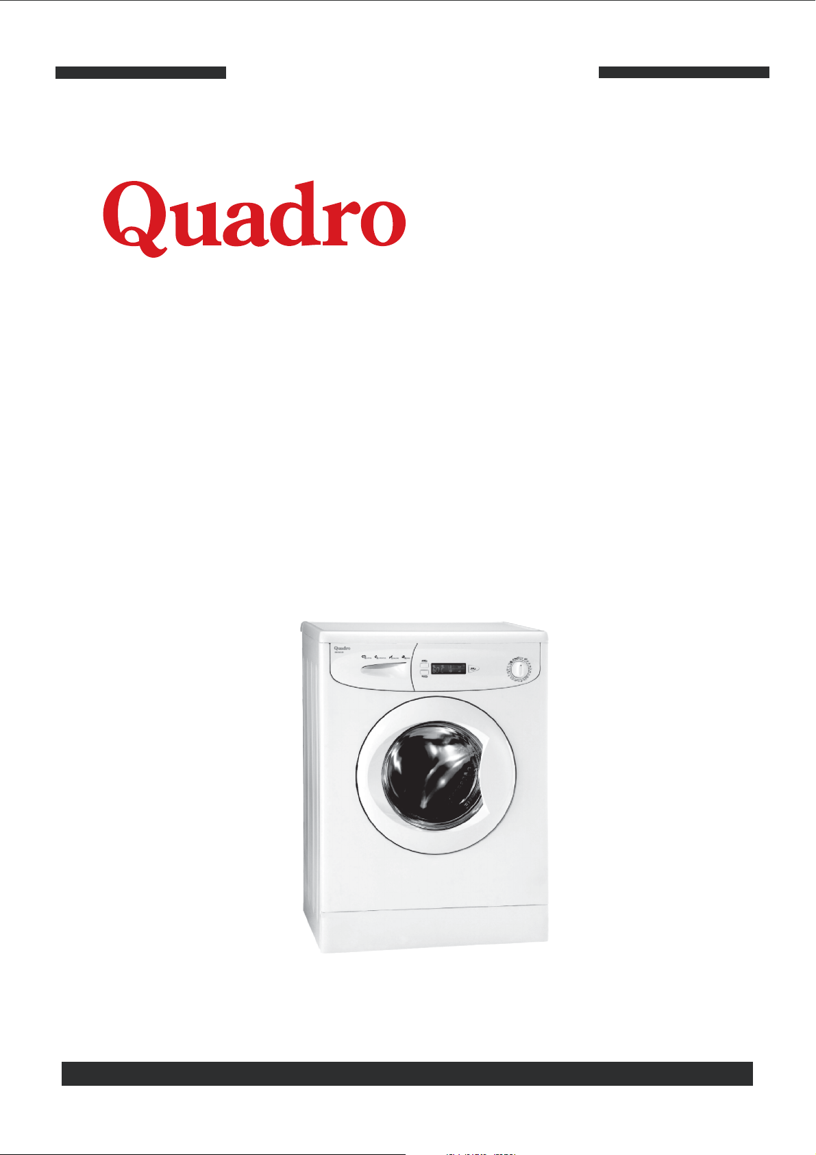
DISASSEMBLY
TOP PLATE
Remove two screws that fix the top-plate at
the back.
Push the top-plate back and pull it up.
DOOR
Remove two screws that fix the door.
Pull the door up.
1
Issue Date:01.08.2003 Documentation Number:
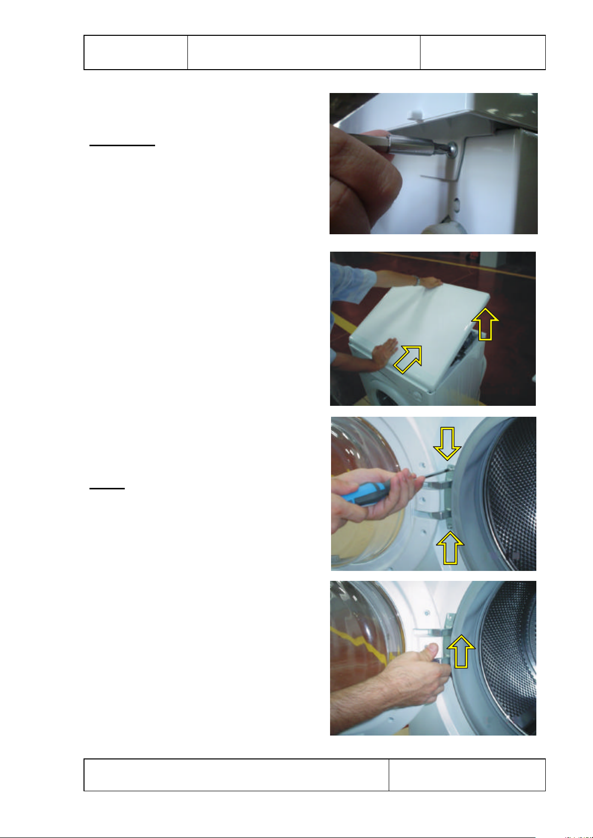
Remove nine screws that fix the door group.
Remove the door inside plastic as it is showing
the picture.
Remove the door hinge as it is showing
the picture.
Remove the door glass as it is showing
the picture.
2
Issue Date:01.08.2003 Documentation Number:
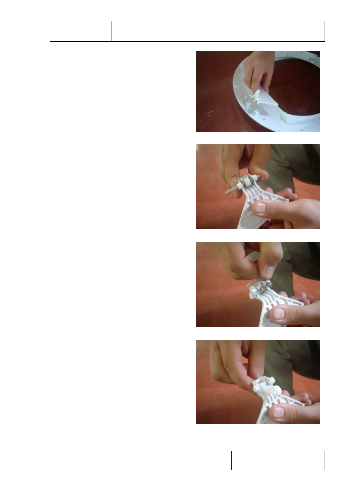
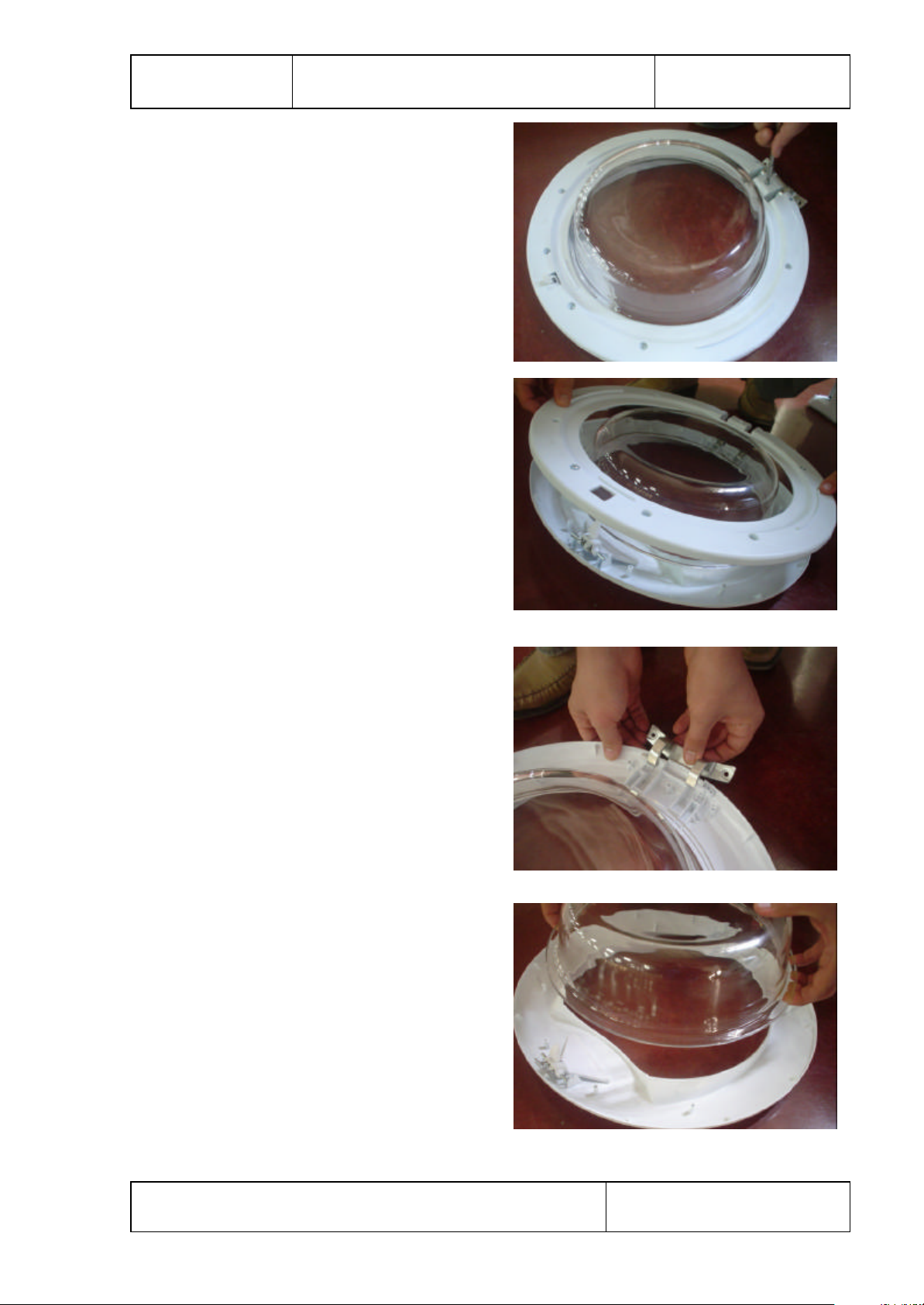
Remove the door handle as it is showing
the picture.
Remove the door handle pim as it is showing
the picture.
Remove the door handle spring as it is showing
the picture.
Remove the door lock tongue as it is showing
the picture.
3
Issue Date:01.08.2003 Documentation Number:
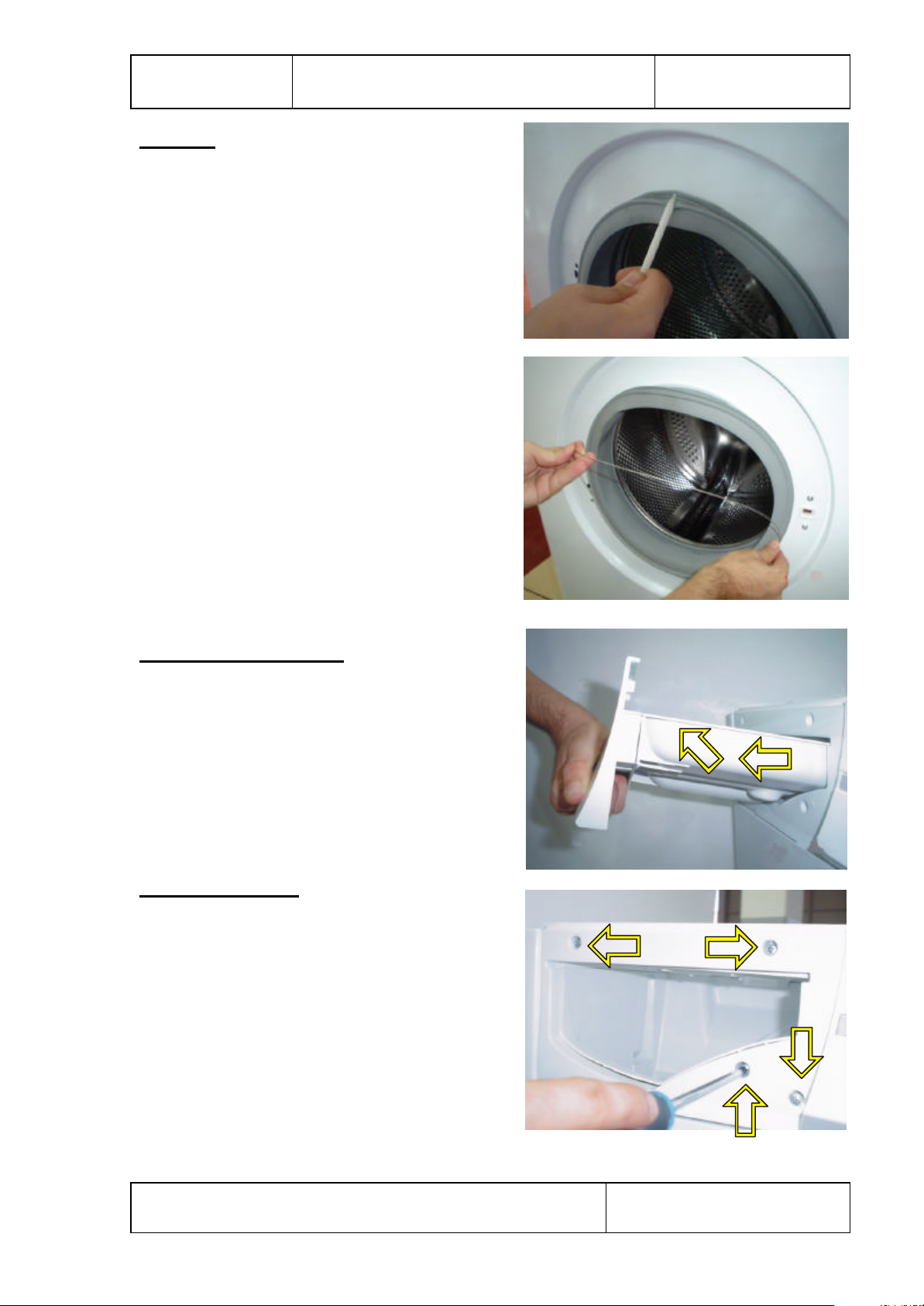
GASKET
Pull the gasket as it is showing in the picture.
Remove the gasket-body fixing string.
DETERGENT DRAWER
Remove the detergent drawer and pull it up
carefully.
CONTROL PANEL
Remove four screws which fix the control
panel to the front panel.
4
Issue Date:01.08.2003 Documentation Number:
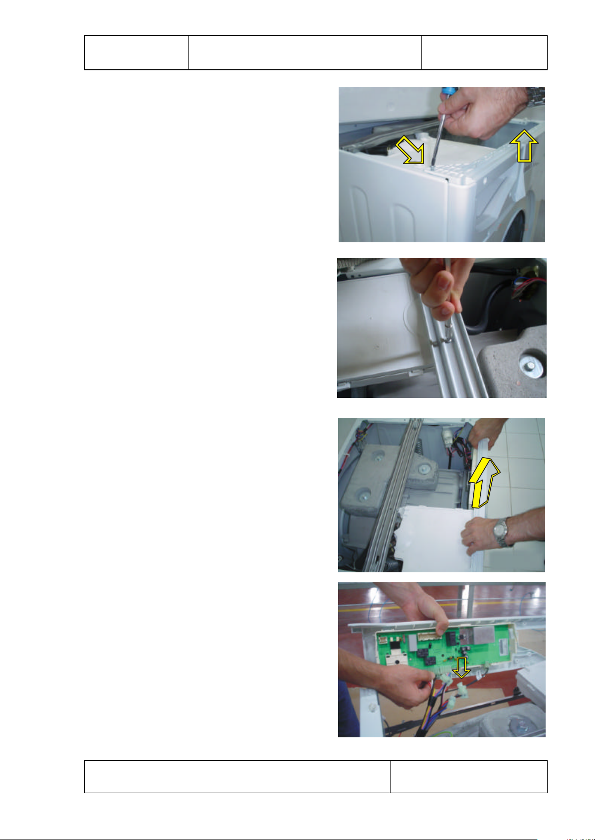
Remove two screws fixing the control panel.
Remove one screws fixing the detergent box
group.
Pull the control panel up.
Remove wires as it is showing in the picture.
5
Issue Date:01.08.2003 Documentation Number:
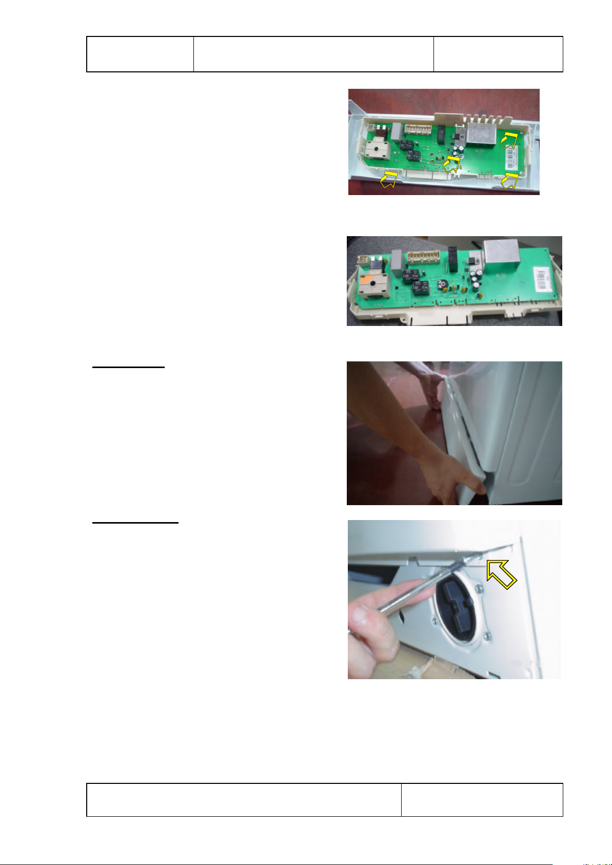
Remove four screws fixing the electronic card.
Remove the electronic card as it is showing
the picture.
KICKPLATE
Remove the kickplate as it is showing
the picture.
FRONT PANEL
Remove two screws fixing the front panel
at the bottom.
6
Issue Date:01.08.2003 Documentation Number:
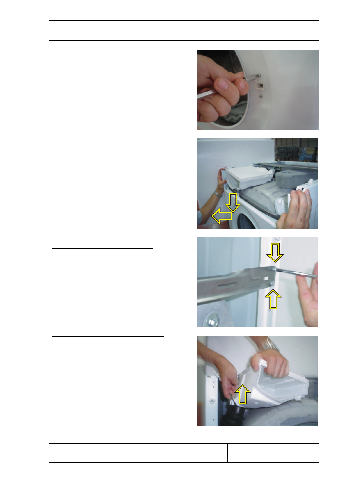
Remove two screws fixing the door lock.
Push it down and remove the front panel.
MEDIUM SUPPORT BRACKET
Remove four screws fixing the panel.
DETERGENT DRAWER HOUSING
Remove the tub seal connector, which is
attached to the detergent drawer housing.
7
Issue Date:01.08.2003 Documentation Number:
Remove the wire that is connected to
the valve.
Remove the valve connection.
Remove the detergent drawer housing
assembly.
8
Issue Date:01.08.2003 Documentation Number:

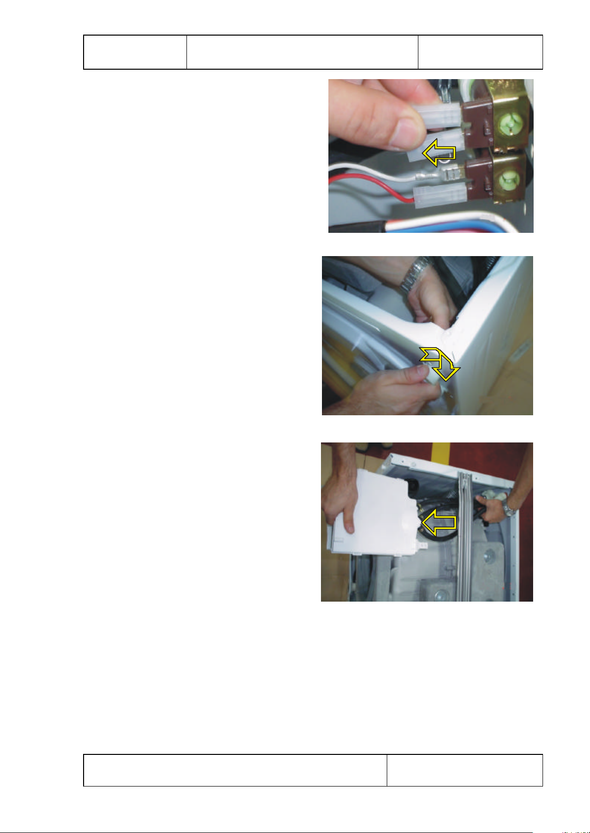
POWER CABLE GROUP AND PARASITE FILTER
Remove the wire that is connected to
the parasite filter.
Remove two screws fixing the parasite filter.
Remove the power cable group as it is showing
the picture.
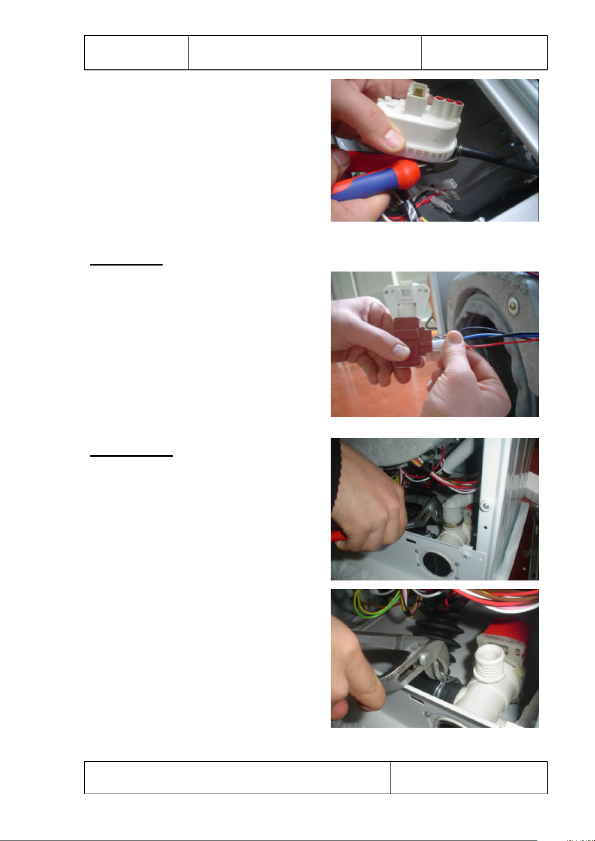
PRESSURE SWITCH
Remove the wire that is connected to
the pressure switch.
Remove the pressure switch as it is showing
the picture.
9
Issue Date:01.08.2003 Documentation Number:
Remove the pressure switch hose handcuffs and
pressure switch hose as it is showing
the picture.
DOOR LOCK
Remove the wire that is connected to
the door lock.
PUMP MOTOR
Remove pipe clip that fixes the drain hose.
Remove pipe clip fixing the tub outlet hose.
10
Issue Date:01.08.2003 Documentation Number:
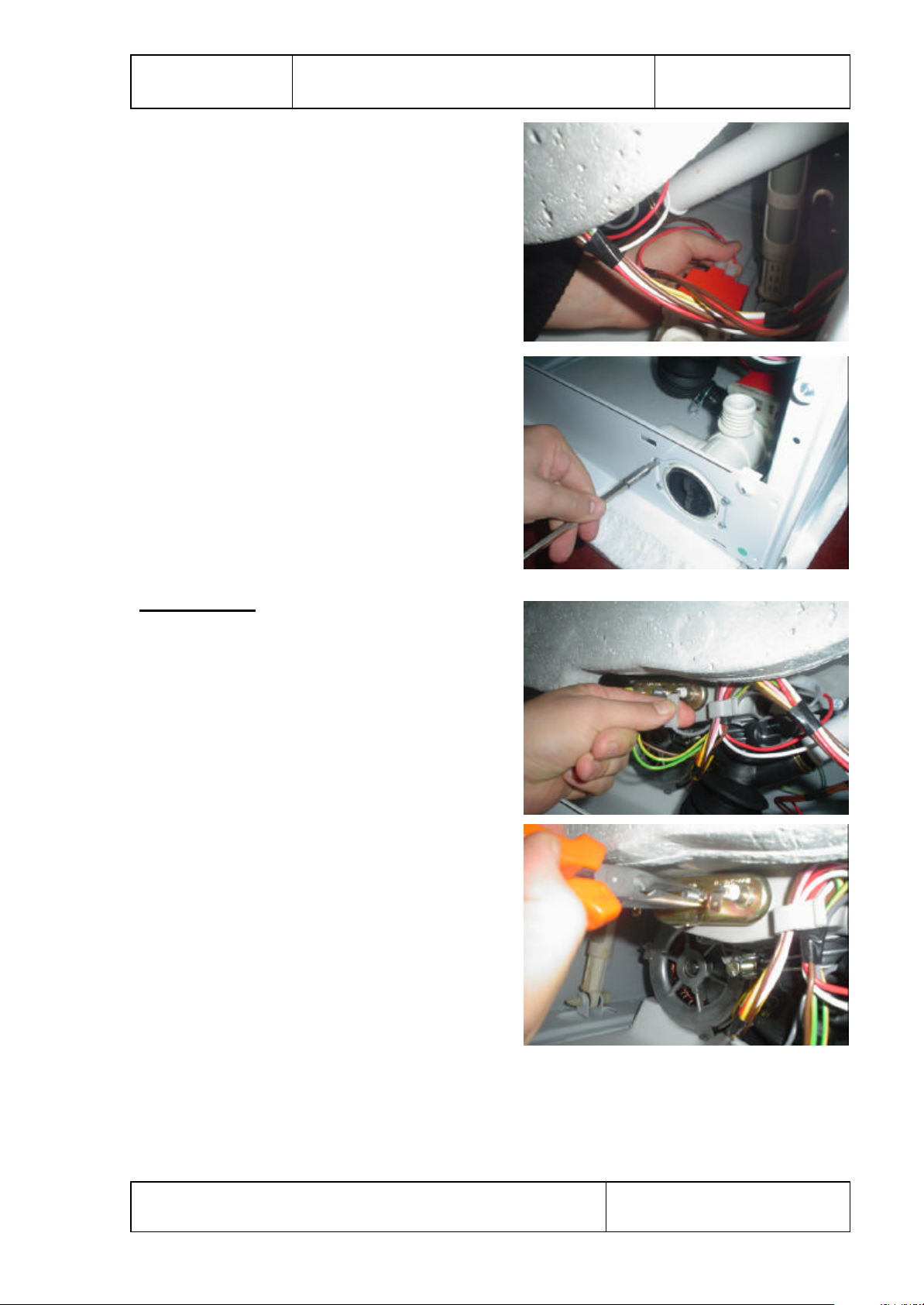
Remove the wire that is connected to
the pump motor.
Remove four screws fixing the pump motor.
RESISTANCE
Remove the wire that is connected to
the resistance.
Remove one nut fixing the resistance.
11
Issue Date:01.08.2003 Documentation Number:
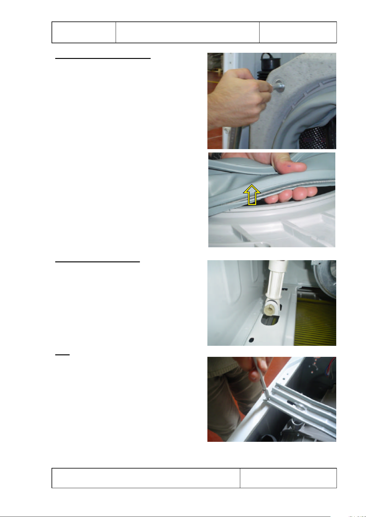
FRONT COUNTERWEIGHT
Remove four screws fixing the front
counterweight on the front and pull it up.
Hold the gasket and gasket-body fixing spring
together, and pull them up.
SHOCK ABSORBER PIM
Remove two pim fixing the shock absorber.
TUB
Remove four screws fixing the spring hanger
sheet iron.
12
Issue Date:01.08.2003 Documentation Number:
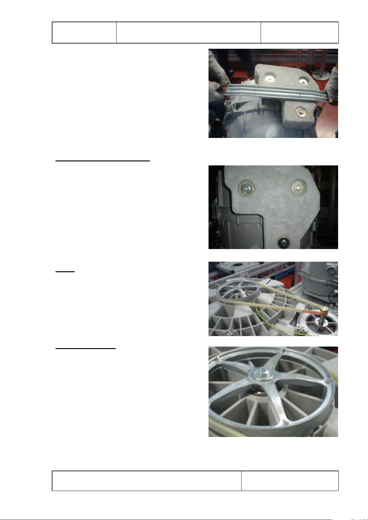
Remove the washing group as it is showing
the picture.
UPPER COUNTERWEIGHT
Remove three screws fixing the upper
counterweight.
BELT
Remove the belt as it is showing
the picture.
DRIVEN PULLEY
Remove one screws fixing driven pulley.
13
Issue Date:01.08.2003 Documentation Number:
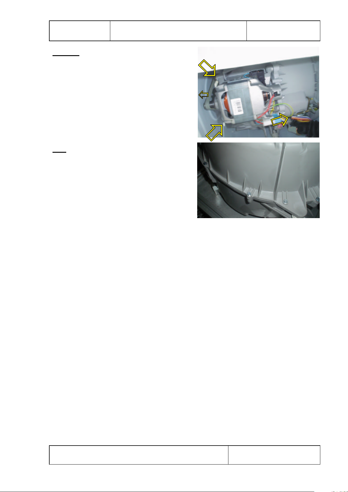
MOTOR
Lay down the machine with an angel of 45°
to the floor. Disconnect wires and remove
two screws fastening the motor under the tub.
Pull the motor up for disassembly.
TUB
Remove seventeen screws fixing tub.
14
Issue Date:01.08.2003 Documentation Number:
FAILURE PROBABLE CAUSE
The spining process is
not done or starts with
delay .
No failure. The
unbalanced load
control may works in
that way.
METHODS OF
ELIMINATION
The unbalanced load
control system will try
to distribute your
clothes in a
homogenous manner.
After your clothes are
distributed, passage to
spining process will be
realized.In the next
washing process,place
your clothes into the
machine in a wellbalanced manner.
SECTION 9: AUTOMATIC FAILURE DETECTION SYSTEM
Your machine is equipped with systems which will both takethe necessary
precautions and warn you in case of any failure by controlling it self constantly
during the washing processes.
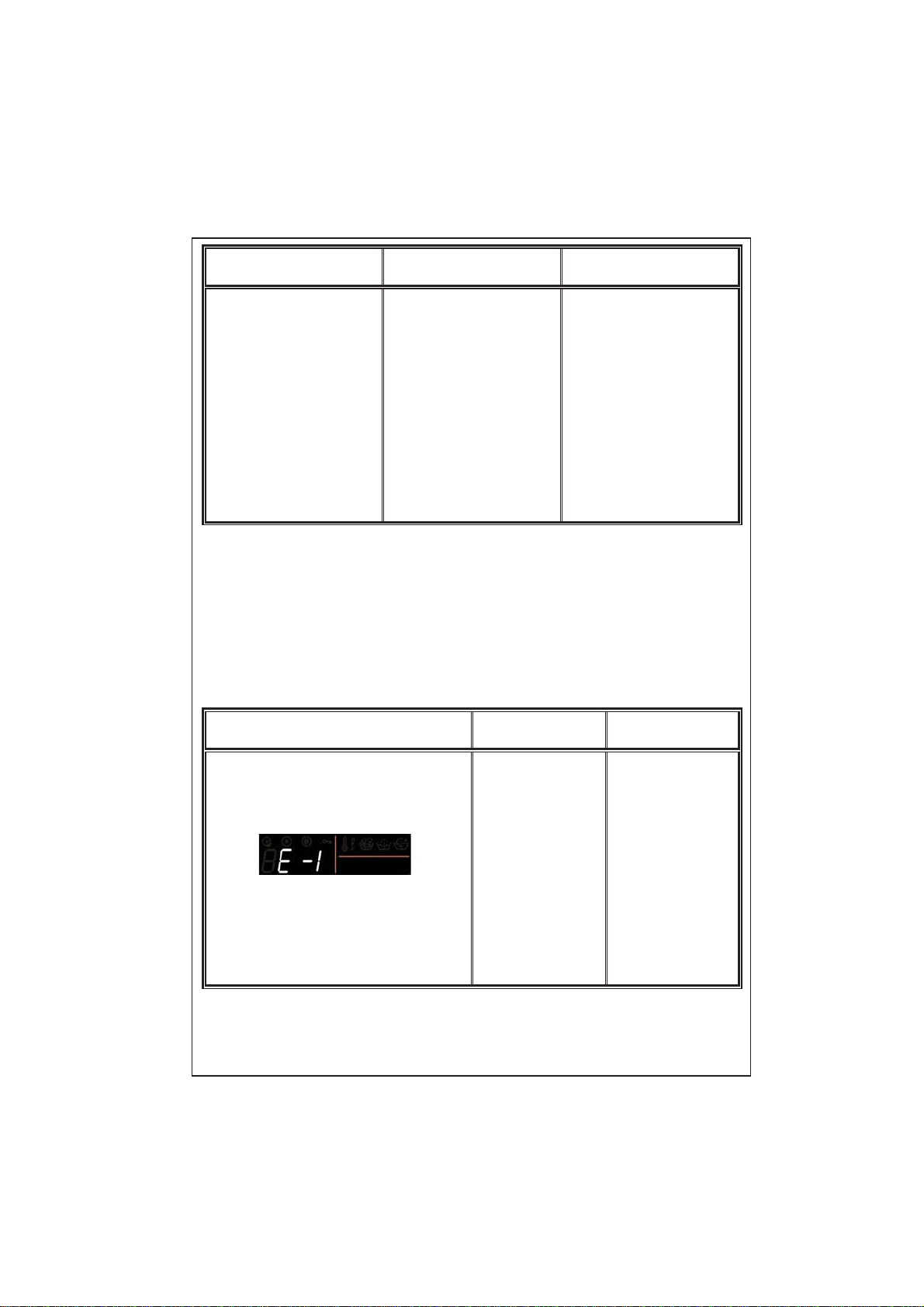
FAILURE CODE
PROBABLE
FAILURE
The door is not
shut properly.
30
THE PROCESS
TO BE DONE
Shut the door
properly so that
you hear the
click. If the
problem
persists, turn off
the machine
unplug and
apply to the
nearest
authorized
service
immediately.
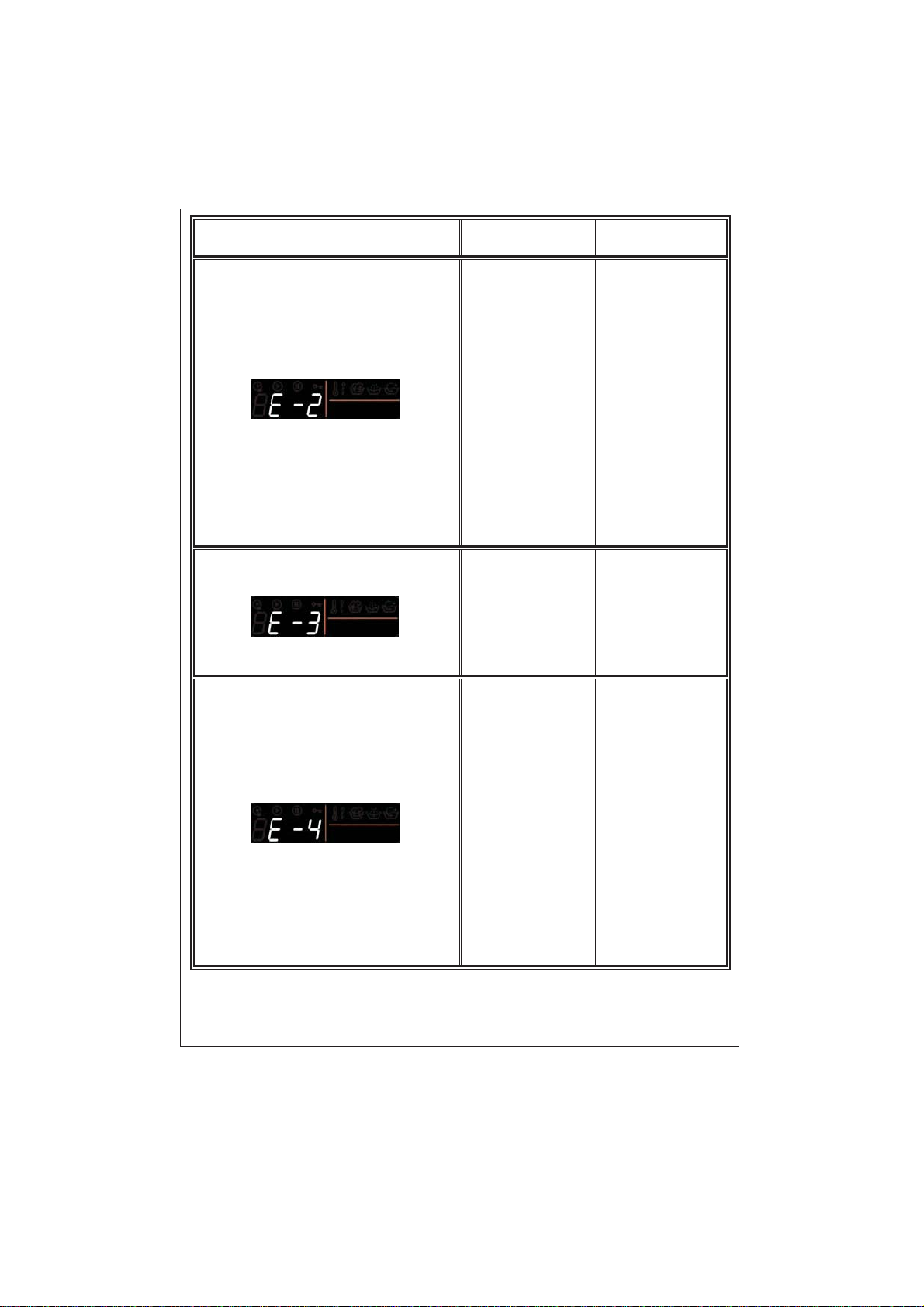
FAILURE CODE
PROBABLE
FAILURE
The water level
in your machine
is below heater.
The pressure of
your water
supply may be
low or locking.
Thepumphas
failed or the
pump filter is
obstructed.
There is an
excessive
amount of water
in your machine.
THE PROCESS
TO BE DONE
Turn on the tap
to the end.Water
may be cut,
check it.If the
problem is still
continuing,your
machine will
automatically
stop after a
while.Unplug
your machine,
turn off the tap
and apply to the
nearest
authorized
service.
Clean the pump
filter.If the
problem
persists,apply to
the nearest
authorized
service.(*)
Your machine
will automatically
drain the water.
After your
machine has
completed the
draining
process,shut
down your
machine and
unplug. Close
the tap and
apply to the
nearest
authorized
service.
(*) See the section regarding the maintenance and cleaning of your machine.
31
 Loading...