

Page 1

AURUM A8
USER INSTRUCTIONS
BEDIENUNGSANLEITUNG
NOTICE D´UTILISATION
MANUAL DE INSTRUCCIONES
Page 2

2
EN
3
Contents
Safety instructions 3-4
Controls fitted on the front of the unit 5
Connections on the back of the unit 6
Remote control (OPTIONAL) 7
Ambient conditions 8
Installing 9
Specifications 10
Inhalt
Sicherheitshinweise 11-12
Bedienelemente an der Gerätevorderseite 13
Anschlüsse auf der Geräterückseite 14
Fernbedienung (optional) 15
Umgebungsbedingungen 16
Inbetriebnahme 17
Technische Daten 18
Sommaire
Indications de sécurité 19-20
Éléments de commande sur l‘avant de l‘appareil 21
Connexions sur l‘arrière de l‘appareil 22
Télécommande (EN OPTION) 23
Conditions d‘environnement 24
Mise en service 25
Caractéristiques techniques 26
Índice
Instrucciones de seguridad 27-28
Elementos de control en el lado delantero del aparat 29
Conexiones en el lado posterior del aparato 30
Mando a distancia (OPCIONAL) 31
Condiciones ambientales 32
Puesta en servicio 33
Datos técnicos 34
We would like to congratulate you on your decision to purchase our AURUM A8 integrated
amplifier. We manufacture top-quality HiFi equipment which we hope will delight you each
time you use it. Our goal in all of this is to truly satisfy the requirements of music lovers just
like you.
Even though you may already be knowledgable in using this type of equipment, we’d still like
to introduce some basic rules and guidance that will enable you to get the best out of your
purchase. Please do take a few moments to read this information.
SAFETY INSTRUCTIONS
Please read through these instructions carefully and follow all of the steps listed here for installing the
equipment. You must abide by all of the warnings and safety instructions that are stipulated on the unit
and in this instruction manual. Keep this manual close to hand so that you can consult it if you have any
questi ons later on.
• The mains power cable and other connecting cables must be laid so that none of them are crushed or
damage d by furniture, a re being trodden on, a nd / or that nobody w ill trip over them.
• Take the power plug out of the s ocket during lighten ing storms or if the e quipment will not be use d for
a long time. A lways pull the plug ou t of the socket and neve r remove it by pulling on th e cable!
• The amplifier‘s speaker terminals must only be connected up to the relevant inputs on the speakers.
You must never connect these terminals up to the electrical mains supply (230V / 115V) as this will
destro y the equipment a nd all interconne cted units im mediately. Ther efore you must neve r fit plugs on
these ca ble connectio ns to ensure that the y can never be mixed up w ith mains plugs.
• Volt ages above 30V c an be present at t he speaker term inals if high volum e is being used. Th erefore you
should neve r touch the termin als when the amplif ier is being used.
• Never use t he equipment in the vi cinity of water, in humid a reas or outdoor s. Moisture can by pass the
electr ical insulati on and this will crea te a life-threate ning risk as is the c ase with all eq uipment that has
not been sp ecially designe d against the pen etration of mois ture.
• Protect the equipment against water being sprayed on it. You must also ensure that no vessels containing l iquid (e.g. vases) ar e placed on top of the eq uipment.
The lightening symbol inside an equal-sided
triangle is used to warn you about the presence of non-insulated components carrying
a dangerous, live voltage that might cause
severe personal injuries.
The exclamation mark inside an equal-sided
triangle indicates that there is important
information available regarding the use and
maintenance of your equipment.
Page 3

4
EN
5
1
7
2
6
3 4
5
A8
Down Up PhonesOn | Menu
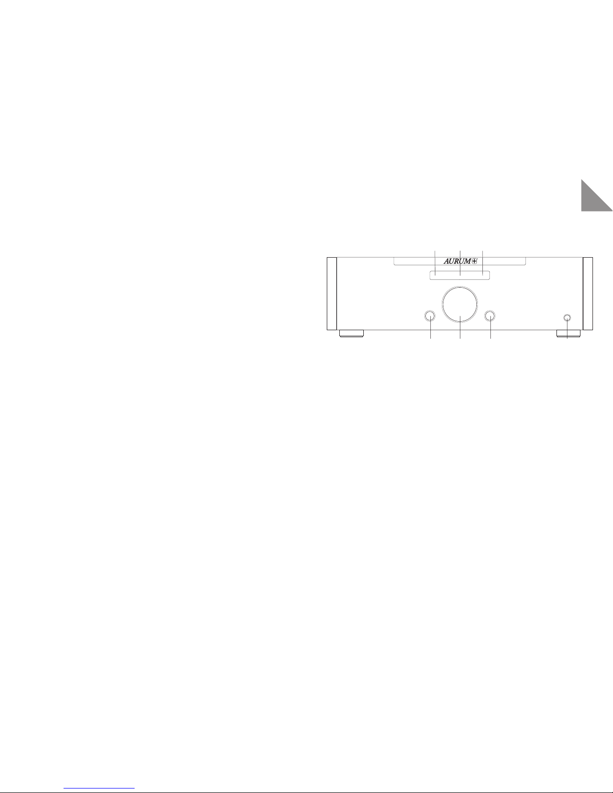
CONTROLS FITTED ON THE FRONT OF THE UNIT
1 Down switch : Press the butt on to navigate down t hrough the menu.
2 Multi-function knob (On, Volume, Source, Ba lance, Bass, Treble) :
Pressing t he knob turns the s et on. Press the kn ob again to turn t he set off (sta ndby).
In stan dby mode, all sett ings are retai ned.
Dependin g on the menu chosen, y ou can turn the kn ob to change sett ings or the volume.
The volume i s set in 1 dB increment s.
3 Up: Press t he button to nav igate up through t he menu.
4 Phones output: Stereo 6.3 mm jack
5 Infrared receiver: This sensor recei ves the infrare d signals from your re mote control.
Always point the re mote control at thi s location and ma ke sure that the senso r is not covered.
6 Display: T his shows status i nformation and m essages that ma ke using the amplif ier easier.
7 Power indicator: This display g lows blue when the set is in standby mode to show that the set can b e
turned o n at any time with th e remote control or t he knob (2).
For operating display:
Flashing o f this indicator s hows that the pr otective cir cuits of the dev ice have disconnec ted the loudsp eaker due to a fault or overloading. The device can now only be put back into operation by using the power
switch o n its rear side.
• Do not place the equipment in the vicinity of a heat source such as an elec tric fire, radiator, oven or
si mila r.
• The s lits and openi ngs in the enclos ure provide the v entilation an d ensure reliable o peration. T hey must
never be mis aligned or covered .
• Burning-out of speci fic components cannot be completely e xcluded, despite the use of protective devices, if t he equipment is severely overloaded by cont inually using very loud sound levels. A fire might
also be caused inside the equipment in theory, as a result of this type of overloading. Therefore the
amplif ier should always be u sed within its lim its and it should no t be left unatte nded.
• Only our technical service should undertake the maintenance of your equipment. Ma intenance will be
necessa ry if any type o f damage occurs, i. e. if the power cable s or plugs are damag ed, if an object fa lls
on the equipment, if the equipment is dropped or if liquid seeps into it. Never open the equipment as
you might to uch the mains volt age (230V / 115V), which is dange rous.
• Only use furniture and other unit s for attaching and putting the equipment on that can be obtained
from or are recommended by the manufacturer. You must ensure that moveable tabletop units or
shelves on which the equipment will be placed are always moved ver y carefully in order to prevent
damage o r injuries from bei ng caused if the equ ipment tips over.
• Contin uously loud volume ca n damage your hea ring!
• Only use a d ry, soft cloth to c lean your equipment .
• Keep th e packing for possi ble transpor tation use late r on and keep the plas tic bag well away fr om children, due to t he risk of asphy xiation.
Page 4

6
EN
7
DO NOT REMOVE COVER. NO USER
SERVICEABLE PARTS INSIDE. REFER
SERVICING TO QUALIFIED PERSONNEL.
CAUTION
RISK OF ELECTRIC SHOCK
DO NOT OPEN
Right
+
-
Left
+
-
quadral GmbH & Co. KG - Am Herrenhäuser Bahnhof 26-28 - D-30419 Hannover
Handmade in Germany
R L
Balanced
RCA 2
Unbalanced
1 2
TOSLINK
Pre OUTUSB SPDIF
Voltage Select
220-240 V 50-60 Hz
110-120 V 50-60 Hz
Fuse
115 V / T 6,3 A L 250 V
230 V / T 3,15 A L 250 V
RCA 1 RCA 3
ON
OFF
Analog IN
Digital IN
max. Power Consumption: 600 W
1 2 3 4 5 6 7 8 9 10
RC -I
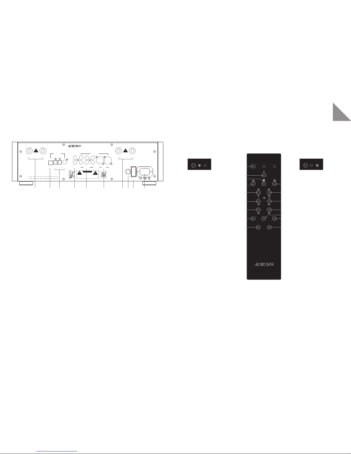
Amplifier operation
1 SELECT butt on
2 ON / OFF button
3 MUTE
4 Volume - minus
5 Volume - plus
6 Left balance
7 Balance plus
8 Signal source dow nwards
9 Signal source upw ards
14 Level set ting (for each
input using buttons 4 & 5)
15 Display brilliance
CD operation
1 SELECT butt on
2 ON / OFF button
3 MUTE
4 Stop
5 Repeat / Pause
6 Search backwards
7 Search forw ards
8 Scan backward through
the title s
9 Scan forward throug h
the titles
10 File down
11 File forward
12 Repeat (ti tle / all)
13 Shuffle
15 Display brilliance
16 Unassigned (optional)
Repeat
RL
Select
AMP
CD
Prog.
Opt.
Random
Display
Select
AMP
CD
Select
AMP
CD
1
2
3
4
6
8
10
12
15
5
7
9
11
13
14
16
RC-II
RC 2 REMOTE CONTROL OPTIONAL
The AURUM amplifiers A8 / P8 / M8 / A5 / A3 and the AURUM CD players C8 / C3 / C5 / C5 DA may be
individually controlled using the RC-2 System Remote Cont rol.
Important note:
If you want t o remotely control the amplif ier or CD player funct ions, you must use the SELECT button t o
select t he relevant operat ing mode beforehan d.
CONNECTIONS ON THE BACK OF THE UNIT
1 Right speaker o utput
2 USB port for connecting to a computer. Your computer installs the necessary driver the first time it is
connected.
3 TosLink SPDIF jack for d igital signals
4 Pre OUT
5 RCA 1-3 stereo jack s for analogue sig nals
6 XLR stereo ja ck for symmetri cal signals
7 Left speak er output
8 Voltage selec tion switch (115V/230V)
9 Power switch (co mpletely disconne cts the set fro m the power supply)
10 Power socket
Page 5

8
EN
9
INSTALLING
1. Select the correct voltage required on the back of the unit amplifier that matches the voltage coming
from the m ains supply. Use th e power cable supp lied in the pack age to connect t he equipment up t o the
mains supply.
2. Check that the u nit is switched of f.
3. Conne ct up the auxili ary units t hat you want to use t o the equipment ‘s inputs. (RC A 1-3, TosLink , SPDIF,
USB) right ch annel = red / lef t channel = whit e or the symmet ric analog XL R inputs can b e used with any
compatible signal source.
(XLR pi n assignments: P in 1= ground; Pin 2 = plus / signa l; Pin 3 = minus)
4. The scre w terminals at the b ack are used for the s peaker connect ions.
5. (See back of the equipment: right channel = 1 / left channel = 7). You must also ensure that the plus
and minus co nnections on t he amplifier con cur with the plus a nd minus connect ions on the spea kers in
order to pr event polarity r eversal.
6. Now swit ch your amplifier o wn.
Switch the mains switch (9) into the ON position on the back. The standby LED on the front will come
on.
7. Now press t he multifunct ion knob (2) on the fro nt or the button (2) o n the remote contr ol to start your
equipment.
Note:
As your A8 u ses a special powe r-saving standb y circuit, you ca n always switch o n / off during norm al operation usin g the multifunc tion knob on the uni t or the RC-2 remote cont rol.
The RC-2 remote control ma kes it easier for you t o change your set tings.
Mute (button 3)
Balance s etting (but tons 6 & 7)
Multilev el display brilliance s etting (but ton 15)
Input level s etting for all inp uts (button 14)
Example: Input leve l setting
Use buttons 8 (-) or 9 (+) to selec t the signal source and then press but ton 14 (Prog.) and use the volume
buttons (4 & 5) to set up the input volume to suit yourself. Press button 14 (Prog.) once again to save the
settings .
AMBIENT CONDITIONS
Notes ab out the removal a nd the correct env ironmentally-f riendly disposa l of old batterie s.
The symbol shown here can be found on the equipment‘s enclosure, the packaging as well as in the documents or the operating manual. It tells you that batteries provided with the equipment as well as those
supplied w ith or fitte d in other units m ust never be dispos ed of in household w aste. They mus t be disposed
of in an environmentally-friendly way (in compliance with the local regulations or European Directives
2002/96/EU and 2006/66/EU).
You should find o ut where the neare st collection p oint for electro nic scrap is or where t he recycling site i s.
Correc t disposal of the eq uipment and the bat teries will help t o preserve our re sources and preven t physical and env ironmenta l damage. The b attery (CR 2032) supplied wit h the remote cont rol contain s lithium and
it must be di sposed of in an enviro nmentally-fri endly way as descr ibed above.
Proceed a s described in t he following sect ion to replace or remo ve the batter y fitted in the r emote control.
1. Undo th e screw in the cover unde rneath the remot e control and then r emove the cover.
2. Rem ove the batter y by sliding it out of it s holder.
3. You must ensure that the new battery‘s polarity is correct when you fit the new one! The side of the
batte ry marked wi th (+) must point upw ards so that it ma kes contac t with the par t of the holde r marked
with (+).
4. Refit the c over and use the scre w to secure it in place.
Page 6

10
11
DE
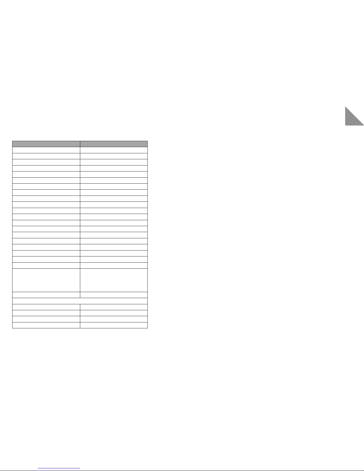
SPECIFICATIONS
A8
Input sens itivity for 1W @8 ohms -16, 3 dB V
Input impedance 47 kOh m
Voltage gain 45dB
Maximum input voltage 6V
Volume adjustment range 80dB
Balance adjustment range +/-6 dB
Gain adjustment range -6dB
Adjustment accuracy 0.1 dB
Channel balance > than 0,05dB
Maximu m voltage at spea ker output 32V
Minimum speaker impedance 2.5 Ohm
Output p ower at 8 ohms 100W
Output p ower at 4 ohms 180W
Frequency response 1Hz-110kHz(-3dB)
Harmonic distortion <0.03%
Signal-to-noise ratio 75 dB unweighted
Mains powe r connection 115V/230V switch
Power consumption in normal mode 30W
Power consu mption at max volu me 6 00W
Power consu mption in stand by mode <0,9W
Inputs 3 RCA
1 Line XLR
2 To sLi nk
1 SPDIF
1 USB PC
Speaker outputs 1 pair
Dimensions
Width in cluding wooden sides 453 mm
Height incl uding feet 130 mm
Depth wi th speaker termin als 345 mm
Weight 13. 86Kg
Wir gratulieren Ihnen, dass Sie sich für unsere AURUM-Vollverstärker A8 entschieden haben.
Es sind Musikliebhaber wie Sie, für deren Ansprüche wir HiFi-Geräte in einer Güteklasse fertigen, die weit über dem Durchschnitt liegen. Auch wenn Sie vieles vielleicht schon wissen,
führen wir im folgenden einige Grundregeln auf, die es Ihnen ermöglichen, Ihre Produkte optimal zu nutzen.
SICHERHEITSHINWEISE
Lesen Sie diese Anleitung bitte sorgfältig durch und befolgen Sie alle Schritte, die für die Inbetriebnahme
angegeben sind. Beachten und befolgen Sie weiterhin alle Warnungen und Sicherheitshinweise, die auf dem
Gerät und in d er Bedienungs anleitung ange geben sind. Depon ieren Sie diese An leitung so, das s Sie bei späteren Fra gen schnell zur Hand is t.
• Das Netzkabel und andere Anschlusskabel müssen so verleg t werden, dass keine Quetschung oder
Beschädigung durch Möbel oder durch Trittbelastung auftr eten kann und Stolperfallen vermieden werden.
• Ent fernen Sie den Net zstecker be i Gewitter od er bei längerer Nic htverwend ung aus der Steckdos e. Das
Netzkabel dar f aus der Steckdose nur durch ziehen des Netzsteckers, nicht aber an dem Kabel selbst
erfolgen.
• Die Lautsprecheranschlussklemmen des Verstärkers dürfen nur mit den betreffenden Eingängen der
Lautsprecher verbunden werden. Eine irgendwie gear tete Verbindung dieser Klemmen mit dem elektrischen Netz (230V/115V) ist nicht erlaubt und f ührt direkt zur sofortigen Zerstörung de s Gerätes und
aller angeschlossenen Produkte. Daher muss es vermieden werden, diese Kabelanschlüsse mit Steckern zu versehen, die auch nur entfernt zu einer Verwechselung mit Netzsteckern führen könnte.
• An den Lautsprecheranschlussklemmen ka nn bei hohen Lautstärken, Spannun-gen von über 30V anliegen. Daher sollten diese nicht während des Betriebes berühr t werden.
• Verwenden Sie das Gerät niemals in der Nähe von Wasser, in Feuchträumen oder im Freien. Wie bei
allen nicht speziell hierfür konstruierten Geräten, kann Nässe die elektrische Isolierung überbrücken
und somit e in lebensgefährli ches Risiko dars tellen.
• Schüt zen Sie dieses Ge rät vor Spritz wasser. Achten Sie bi tte darauf, das s keine Gefäße, die F lüssigkeiten entha lten (z.B. Vasen) , auf dem Gerät abge stellt werden.
Das Blitzsymbol in einem gleichschenkligen
Dreieck warnt vor nicht isolierten Komponenten mit gefährlicher Spannung, die zu
ernsthaften Personenschäden führen kann.
Das Ausrufungszeichen in einem gleichschenkligen Dreieck kennzeichnet wichtige
Hinweise für die Nutzung und Wartung Ihres
Gerätes.
Page 7
1
7
2
6
3 4
5
A8
Down Up PhonesOn | Menu
12
13
DE
• Stellen Sie das Produkt nicht in der Nähe von Wärmequellen wie Heizstrahler, Heizkörper, Öfen oder
anderen Geräten auf.
• Schli tze und Öffn ungen im Gehäuse dien en der Entlüft ung und sorgen für z uverlässigen Be trieb. Daher
dürfen sie nicht verstellt oder abgedeckt werden.
• Bei einer massiven Überlastung der Geräte durch sehr große Lautstärken ist das Durchbrennen einzelner Bauelemente trotz Sicherungseinrichtungen nicht vollständig auszuschließen. In der Theorie
könnte sog ar ein Brand inn erhalb eines Ge rätes in einem der artigen Übe rlastungs fall entste hen. Daher
sollten Verstärker die in diesem Grenzbereich betrieben werden, nicht unbeaufsicht igt bleiben.
• Die War tung Ihres Geräte s überlassen Sie bi tte ausschließli ch dem technischen S ervice. Wart ung wird
notwendig, bei jeglicher Art von Schäden, d.h. bei beschädigten Netzkabeln und Steckern, oder nach
dem Herab fallen von Gegens tänden auf da s Gerät, sowie de m Sturz des Gerät es selbst oder nac h dem
Eindringen von Flüssigkeiten . Öffnen Sie das Gerät nie selbst, da j eder Umgang mit der Ne tzspannung
(230V/115V) lebensgefährlich ist.
• Verwe nden Sie bitte au sschließlich Möb el und andere Gerä te zum Anbringen un d Draufstelle n der Produkte, die beim Hersteller erhältlich sind oder von Ihm empfohlen werden. Beachten Sie bitte, dass
fahrb are Tischger äte oder Regale , auf denen die Pro dukte plat ziert werden, s ehr vorsicht ig zu bewegen
sind, um Schäden oder Verletzungen durch ein umkippen zu vermeiden.
• Sehr große Laut stärken im Dauer betrieb können für den Anwender zu gesundheits-schädlichen Auswirkungen führen!
• Verwen den Sie zur Reinigung Ihr er Geräte nur ein tro ckenes und weiches Tuch.
• Bit te heben Sie die Verpac kung für einen event uell späteren Transpor t auf, und halten Sie di e Polybeutel von Kin dern fern, da hier be i unsachgemäßen Um gang ein Erstic kungsrisiko bes teht.
BEDIENELEMENTE AN DER GERÄTEVORDERSEITE
1 Down: Drü cken Sie die Taste um sich abw ärts durch da s Menü zu navigieren .
2 Mu ltifunktionsdr ehknopf (On, Volume, So urce, Balance, Bass , Treble):
Durch Drü cken des Drehknopf es schalten Sie da s Gerät ein.
Drücken Si e den Drehknopf ern eut, um das Gerät w ieder auszuscha lten (Standby).
Im Standby-Betrieb bleiben alle Einstellungen erhalten.
Mit dem Drehknopf können Sie je nach ausgewähltem Menü die Einstellungen oder die Lautstärke
durch drehen ändern.
Die Laut stärke wird in 1dB S chritten einge stellt.
3 Up: Drücke n Sie die Taste um sich auf wärts durch d as Menü zu navigiere n.
4 Kopfhörer Ausgang: Stereo 6 .3mm Klinken Buchse
5 Infrarotempfänger: Dieser Sensor empfängt die Infrarot signale Ihrer Fernbedienung.
Richten Sie die Fernbedienung stets auf diesen Bereich, und achten Sie darauf, dass der Sensor nicht
verdeckt wird.
6 Display: Hier werden Statusinformationen und Meldungen angezeigt, die die Handhabung des Verstär-
kers vereinfachen.
7 Betriebsanzeige: Diese Anzeige leuchtet blau, wenn sich das Gerät im Standby-Modus befindet und
signalis iert damit, da ss Sie das Gerät je derzeit mit der Fer nbedienung oder mi t dem Drehknopf (2)
einschalten können.
Zur Betriebsanzeige:
Sollte diese Anzeige blinken, haben die Schutzschaltungen des Gerätes, die Lautsprecher im Fehler- oder
Überlastungsfall, abgeschaltet. Das Gerät kann nur durch eine erneute Betätigung des Netzschalters auf
der Geräterückseite zurück geset zt werden.
Page 8
RC -I
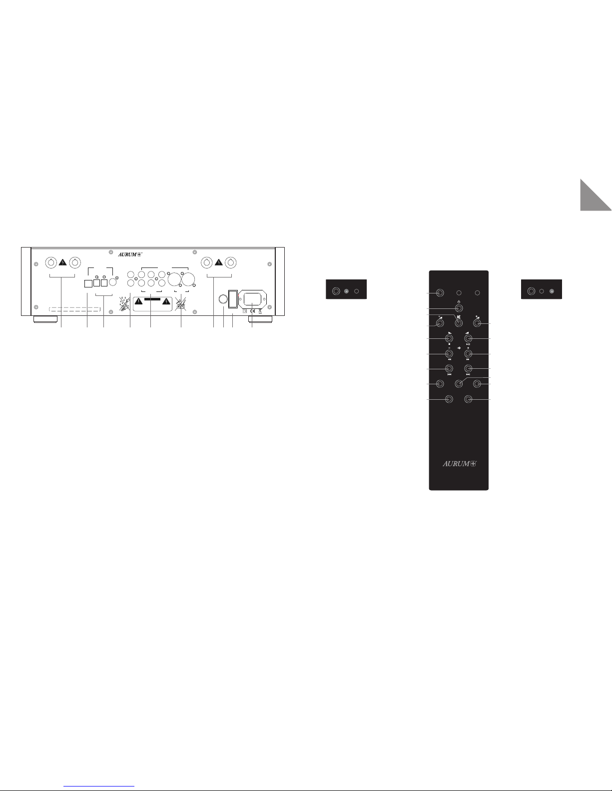
Verstärkerbetrieb
1 SEL EC T-Ta s te
2 ON/OFF-Taste
3 Stummschaltung (MUTE)
4 L autstärk e Minus
5 L autstärk e Plus
6 B alance Links
7 B alance Rechts
8 Si gnalquelle Abwä rts
9 Signalq uelle Aufwär ts
14 Pegelei nsteller (für jede n
Eingang mi t Taste 4+5 )
15 Display-Helligkeit
CD-Betrieb
1 SEL EC T-Ta s te
2 ON/OFF-Taste
3 Stummschaltung (MUTE)
4 oh ne Funktion
5 oh ne Funktion
6 Stopp
7 Wiedergabe/Pause
8 Su chlauf Rückwä rts
9 Suchlauf Vorwärt s
10 Titel sprung Rückwär ts
11 Titel sprung Vorwär ts
12 Wiederholung (Titel/Alle)
13 Zufallswiedergabe
15 Display-Helligkeit
16 ohne Funk tion (nur C5 DA
externer D/A-Wandler)
Repeat
RL
Select
AMP
CD
Prog.
Opt.
Random
Display
Select
AMP
CD
Select
AMP
CD
1
2
3
4
6
8
10
12
15
5
7
9
11
13
14
16
RC-II
DO NOT REMOVE COVER. NO USER
SERVICEABLE PARTS INSIDE. REFER
SERVICING TO QUALIFIED PERSONNEL.
CAUTION
RISK OF ELECTRIC SHOCK
DO NOT OPEN
Right
+
-
Left
+
-
quadral GmbH & Co. KG - Am Herrenhäuser Bahnhof 26-28 - D-30419 Hannover
Handmade in Germany
R L
Balanced
RCA 2
Unbalanced
1 2
TOSLINK
Pre OUTUSB SPDIF
Voltage Select
220-240 V 50-60 Hz
110-120 V 50-60 Hz
Fuse
115 V / T 6,3 A L 250 V
230 V / T 3,15 A L 250 V
RCA 1 RCA 3
ON
OFF
Analog IN
Digital IN
max. Power Consumption: 600 W
1 2 3 4 5 6 7 8 9 10
14
15
DE
ANSCHLÜSSE AUF DER GERÄTERÜCKSEITE
1 Rechter Laut sprecherausgang
2 USB Eingang zum Anschluss an einen Computer. Die benötigten Treiber installiert Ihr Computer beim
Erst Anschluss selbständ ig.
3 TosLink SPDIF Ein gang für digita le Signale
4 P re OUT
5 R CA 1-3 Stereo E ingänge für anal oge Signale
6 X LR Stereo Eingang f ür Symmetrische S ignale
7 Linker Laut sprecherausgang
8 Spa nnungswahlschalter (115V/230V)
9 Ne tzschalter ( trennt das Gerät ko mplett von der Net zversorgun g)
10 Netzbuchse
FERNBEDIENUNG RC 2 OPTIONAL
Mit der Sys tem-Fernbedie nung RC-2 können die AURUM-Ver stärker A8 / P 8 / M8 / A5 / A3 und die AU RUM
CD-Player C 8 / C3 / C5 / C5 DA individuell angesteuert werden.
Wichtiger Hinweis:
Um die Funktionen eines Verstärkers oder CD-Spielers fernsteuern zu können, muss die entsprechende
Betriebsar t vorher mit der Anwahl-Taste (SELECT ) gewählt werden.
Page 9

16
17
DE
UMGEBUNGSBEDINGUNGEN
Die Ferns teuerung hat eine Rei chweite von bis zu 6 m und fu nktioniert e inwandfrei in eine m Einstrahlwin kel von bis zu 30° be zogen auf die Geräte vorderseite. St aub am Sender oder Sc hmutz vor dem Empf angssensor und der Betrieb in der Nähe von Leuchtstof fröhren kann die Reichweite verringern. Eine direkte
Sichtverbindung zwischen Sender und Empfänger ist erfo rderlich.
Hinweise zum Ausbau und zur umweltgerechten Entsorgung verbrauchter Batter ien.
Das abgebildete Symbol kann auf dem Gehäuse eines Produkts, dessen Verpackung sowie in den Unterlagen oder der Bedienungsanleitung auftreten. Es zeigt an, dass sowohl das Produkt selbst, als auch die
mitgeli eferten oder im Pr odukt verbaut en Batterien nie mals in den Hausmüll gela ngen dürfen. Sie m üssen
umweltgerecht (entsprechend lokaler Richtlinien oder gemäß der Europäischen Richtlinien 2002/96/EC
und 2006/66/EC) entsorgt werden.
Bitte informieren Sie sich , wo in Ihrer Nähe die nächs te Abgabeste lle für Elektronik-schrot t oder ein Recycling-Hof is t.
Der korrek te Umgang mit dem Produkt und den Batterien hilft Recourcen zu schonen und beugt körperlichen und Umweltschäden vor. Die in der Fernbedienung mitgeliefer te Bat terie (CR2032) enthält Lithium
und muss, wie oben beschrieben, umweltgerecht entsorg t werden.
Folgen Sie den nachstehenden Hinweisen, um die Batterie in der Fernbedienung zu erneuern oder auch zu
entfernen.
1. Entfernen Sie die Schrauben auf der Fernbedienungsunter seite und heben Sie den Deckel ab.
2. Entfernen Sie die Batterie durch einfaches schieben aus ihrer Halterung.
3. Achten Sie bei dem Erneuern der Batterie auf die Polarität! Die mit einem (+) Pluszeichen versehene
Seite der B atterie muss na ch oben zu der ebenfa lls mit (+) gekennzeichnet en Halterung weis en.
4. Setzen Si e den Gehäusedecke l wieder auf und befe stigen ihn mit den Sc hrauben.
INBETRIEBNAHME
1. Verbinde n Sie Ihr Gerät mit dem be iliegenden Netzk abel mit dem Strom netz.
2. Stellen Sie sicher, das s das Gerät ausges chaltet ist.
3. Verbinden Sie die Geräteingänge mit den Ihnen zur Verfügung stehenden Zuspielgeräten.
(RCA 1-3, TosLink, SP DIF, USB) Rechter Kanal = Ro t / Linker Kanal = Weiß o der die symmetr ischen ana-
logen XLR E ingänge für den Eins atz mit einer beli ebigen kompatiblen S ignalquelle.
(Kontak tbelegung des X LR-Anschlusse s: Pin 1= Masse; Pin 2 = Plus/ Signal; Pin 3 = Minus)
4. Der Anschluss der Lautsprecher erfolgt an den rückseitigen Schra ubklemmen.
5. (Siehe Geräterückseite: Rechter Kanal = 1 / Linker Ka nal = 7). Achten Sie bitte darauf, dass jeweils der
Plus und Minus Anschluss am Verstärker auch mit dem Plus und Minus Anschluss an den Lautsprechern verbunden ist, um Verpolungen zu vermeiden.
6. Schalten Sie Ih ren Verstärker nu n ein.
Netzs chalter (9) auf der Ger äterücksei te auf ON. Die Stand by LED auf der Front leuc htet.
7. Drücke n Sie nun den Multif unktionsdr ehknopf (2) auf der Ge rätefront ode r die Taste (2) auf der Fern be-
dienung , um Ihr Gerät in Betri eb zu nehmen.
Hinweis:
Da Ihr A8 über eine besonders st romsparende Standby-Schaltung ver fügt, kann die An-/Ausschaltung im
normalen Betrieb stets über den Multifunktionsdrehknopf am Gerät oder mit der Fernbedienung RC-2 erfolgen.
Mit der Fernbedienung RC-2 stehen Ihnen erweiterte Komforteinstellungen zur Verfügung.
Stummsch altung / Mute (Tast e 3)
Balance E instellung (Tasten 6 + 7 )
Mehrst ufige Anpassu ng der Displayhelligke it (Taste 15)
Eingang spegeleinstellu ng für alle Eingänge ( Taste 14)
Beispiel: Eingangspegeleinstellung
Signalquelle mit den Tasten 8 (-) oder 9 (+) anwählen, dann Taste 14 (Prog.) betätigen und mit den Volume - Tasten (4 +5) die gewünschte Eingangslautstärke einstellen. Zum speichern Taste 14 (Prog.) erneut
drücken.
Page 10

19
FR
18
TECHNISCHE DATEN
A8
Eingang sempfindlichke it für 1W an 8 Ohm -1 6,3 dBV
Eingangsimpedanz 47k Ohm
Spannungsverstä rkung 45dB
Maximale Einga ngsspannung 6V
Regelbereich Volume 80dB
Regelbereich Balance +/-6 dB
Regelbereich Vorpegel -6dB
Regelgenauigkeit 0.1 dB
Kanalgleichheit besser 0,05dB
Max. Spannung am Lautsprecherausgang 32V
Minimale Lautsprecherimpedanz 2.5 Ohm
Ausgangleistung an 8 Ohm 100W
Ausgangleistung an 4 Ohm 180W
Frequenzgang 1Hz-110kHz(-3dB)
Harmonische Verzerrungen <0.03%
Geräuschspannungsabstand 75dB unbewertet
Netzanschluss 115V/230V umschaltbar
Leistungsaufnahme Normalbe trieb 30W
Leistungsaufnahme Vollaussteuerung 600W
Stromaufnahme standby <0,9W
Eingänge 3 RCA
1 Line XLR
2 To sLi nk
1 SPDIF
1 USB PC
Lautsprecherausgänge 1 P aar
Abmessungen:
Breite mit Seitenteilen 453 mm
Höhe mit Füssen 13 0 mm
Tiefe mit Lautsprecherklemmen 345 mm
Gewicht 13. 86Kg
Nous vous remercions d‘avoir porté votre choix sur notre amplificateur intégré A8 AURUM.
C‘est à l‘intention d‘amateurs (au sens noble du terme) de musique tels que vous, que nous
créons des app areils HiFi, d‘un niveau de quali té largement supérieur au n iveau standard. Bien
que nous soyons conscients de vos connaissances approfondies en la matière, nous nous permettons de reprendre ici quelques règles fondamentales qui vous permettront d‘utiliser votre
produit de façon optimale.
INDICATIONS DE SÉCURITÉ
Veuillez pren dre soin de lire att entivement cet te notice d’ut ilisation et de s uivre toutes l es étapes indi quées
pour la mise en service. Veuillez tenir compte et respecter tous les avertissements ainsi que les informations ayant trait à la sécurité mentionnés dans le mode d‘emploi. Conservez cette notice d‘utilisation de
façon à pou voir la retrouver r apidement ultér ieurement en cas de q uestions.
• Le cordon secteur et les autres câbles de connexion doivent être disposés de façon à ne subir aucun
dommage e t à éviter tout risq ue de trébuchemen t.
• En cas d‘or age ou de non utilisat ion prolongée de votre appareil, débranchez le cordon sec teur. La déconnexi on du cordon secteu r de la prise murale do it se faire uniquem ent par la fiche elle-m ême et non
pas en tir ant sur le câble.
• Les bornes de connexion des haut-parleurs de votre amplificateur ne doivent être utilisées que pour
raccorde r vos haut-parleur s. Il est interdi t de procéder à une mi se à la terre de quelq ue façon que ce soit
de ces born es par le biais du rése au électrique (23 0 V)/115 V) sous peine d‘une destruct ion immédiate
de l‘appareil ainsi que de tout autre appareil connecté. Ne pas équiper ces raccordements de connecteurs re ssemblant à ceux du se cteur.
• Il se peut, à volume impor tant , qu‘il y ait des tensions dépassant les 30 V à la sortie des bornes de
connexi on des haut-parleu rs. Il est par c onséquent dang ereux d’entrer en c ontact avec ce lles-ci lorsqu e
l‘appar eil est en foncti on.
• Ne jamais u tiliser l‘appareil à proximité de l‘eau, da ns des pièces humides ou en plein air. Comme c‘est
le cas avec t ous les appareils n on conçus à cet effet , l‘humidité peut e ntraîner un cour t-circuit de l‘isolation éle ctrique et cons tituer ainsi un ri sque létal.
• Placez cet appareil à l‘abri des éclaboussures. Evitez de déposer des récipients contenant des liquides
sur votre a ppareil (des vas es par exemple).
Ce symbole a pour but d’attirer l’attention
de l’utilisateur sur la présence, à l’intérieur
du boîtier de l’appareil, de composants non
isolés pouvant présenter un risque d’élec-
trocut ion pour les êtres hum ains.
Ce symbole identifie des informations
import antes ayant trait à l‘utilisation et à
l‘entretien de votre appareil.
Page 11

1
7
2
6
3 4
5
A8
Down Up PhonesOn | Menu
20 21
FR
• Ne disposez jamais l‘appareil à proximité de sources de chaleur telles que radiateurs en tous genres,
fours ou au tres système s produisant de la ch aleur.
• Les fe ntes et ouvert ures du boîtier s ont prévues pour la v entilation et ga rantissent un f onctionneme nt
fiable. N ’obstruez et ne bou chez donc jamais ce s ouvertures .
• En cas de surcharge anormale, il n‘est pas totalement exclu que certains des composants puissent
être détruits en dépit de la pr ésence de disposit ifs de protecti on. Il est donc imprudent de lais ser sans
surveill ance un appareil su bissant une surch arge anormale .
• Veuillez la isser au seul ser vice technique l e soin de la maintena nce de votre appa reil. Il faudra ef fectuer
une maint enance en cas de domm age quel qu‘il soit , donc en cas d‘endomma gement d‘un cordon se cteur et de pr ises, en cas de chut e d‘objets sur l‘app areil ainsi qu‘en cas de c hute de l‘appareil lui-même
ou de la pénét ration de liquid es à l‘intérieur d e ce dernier. Ne procédez j amais vous-même à l ‘ouverture
de l‘appareil, sachant que tout contact avec la tension du secteur (230 V/115 V) présente un danger
mortel.
• Pour di sposer vos appa reils, n’utiliser que d es meubles ou dispo sitifs propo sés ou recommand és par le
fabric ant. Déplace z particul ièrement prude mment les dispos itifs roulan ts, afin d’évit er un basculem ent
accidentel.
• Le fonc tionnement perma nent à des volumes trop élevés pe ut se traduire par d es dommages audit ifs
irréversibles pour l’utilisateur.
• Le net toyage de votre a ppareil ne doit se f aire qu’à l’aide d’un chi ffon doux et sec .
• Conservez l‘emballage pour un transpor t ultérieur. Gardez les sacs plastiques hors de la portée des
enfant s sachant qu‘une ut ilisation incor recte compor te des risques de su ffocation.
ÉLÉMENTS DE COMMANDE SUR L‘AVANT DE L‘APPAREIL
1 Bouton Ba s : Appuyez sur le bout on pour naviguer ver s le bas dans le menu.
2 Molette multifonction (Allumage, Volume, Source, Balance, Ba sses, Aigües)
L‘appareil est all umé en appuyant sur l a molette. Appuy ez à nouveau sur la molet te pour éteindr e l‘ap-
pareil ( Veille). En mode Veille tous le s réglages sont con servés.
En tourna nt la molette, en fo nction du menu cho isi, vous pouvez mod ifier les réglag es ou le volume.
Le volume es t réglé par palie rs de 1dB.
3 Haut : Appu yez sur le bouton pour n aviguer vers le haut d ans le menu.
4 Sortie c asque : Prise Jack s téréo 6,3 mm
5 Récepteur i nfrarouge : Ce capte ur réceptionne le sig nal infraroug e provenant de votre t élécommande.
Dirigez toujour s la télécommande da ns cette zone et vei llez à ce que le capteur ne s oit pas recouve rt.
6 Écran : C‘es t ici que les informa tions d‘état et les me ssages qui faci litent la manipula tion de l‘amplif ica-
teur sont affichés.
7 Voyants de fonctionnement : Ce voyant s‘allume bleu lorsque l‘appareil est en mode Veille et indique
que vous pou vez à tout moment allu mer l‘appareil à l‘a ide de la télécomman de ou de la molette (2).
Remarque :
le clignotement de ce témoin indique que les circuits de protection ont détecté une anomalie de fonc tionnement (sur charge, défec tuosité) et ont m is l’appareil hor s service. La r emise en foncti on ne pourra se fa ire
qu’à l’aide de l ’interrupteur s ecteur (11) à l’arr ière de l’appareil.
Page 12

Commande de l‘amplificateur
1 Touche SEL ECT
2 Touche Marche/Arrêt (ON/OFF)
3 Sourdine (MUTE)
4 Volume – (diminuer)
5 Volume + (augmenter)
6 Balance Gauche
7 Balance Droite
8 Source de signal Précéd ente
9 Source de signal Suivante
14 Réglage de niveau (pour chaque
entrée par le biais des touches
4+5)
15 Luminosi té de l‘affichage
Commande du
lecteur de CD
1 Touche SEL ECT
2 Touche Marche/Arrêt
(ON/OFF)
3 Sans fonction (option)
4 Arrêt Lecture
5 Lecture/Pause
6 Recherche Arrière
7 Recherche Ava nt
8 Saut morceau Arrière
9 Saut morceau Avant
10 Fichier Arrière
11 Fichier Avant
12 Relecture
(Morceau/Tous)
13 Lecture aléatoire
15 Luminosi té de
l‘affichage
16 Sans fonction (option)
RC -I
Repeat
RL
Select
AMP
CD
Prog.
Opt.
Random
Display
Select
AMP
CD
Select
AMP
CD
1
2
3
4
6
8
10
12
15
5
7
9
11
13
14
16
RC-II
DO NOT REMOVE COVER. NO USER
SERVICEABLE PARTS INSIDE. REFER
SERVICING TO QUALIFIED PERSONNEL.
CAUTION
RISK OF ELECTRIC SHOCK
DO NOT OPEN
Right
+
-
Left
+
-
quadral GmbH & Co. KG - Am Herrenhäuser Bahnhof 26-28 - D-30419 Hannover
Handmade in Germany
R L
Balanced
RCA 2
Unbalanced
1 2
TOSLINK
Pre OUTUSB SPDIF
Voltage Select
220-240 V 50-60 Hz
110-120 V 50-60 Hz
Fuse
115 V / T 6,3 A L 250 V
230 V / T 3,15 A L 250 V
RCA 1 RCA 3
ON
OFF
Analog IN
Digital IN
max. Power Consumption: 600 W
1 2 3 4 5 6 7 8 9 10
22 23
FR
CONNEXIONS SUR L‘ARRIÈRE DE L‘APPAREIL
1 Sor tie haut-parleur Droite
2 Port USB pour le r accordement d‘un or dinateur. Votre ordinat eur installe les pil otes nécessai res
automatiquement lors du premier raccordement.
3 Entrée SPDIF TosLin k pour signal numér ique
4 P re OUT
5 Entrées sté réo RCA 1 à 3 pour signa l analogique
6 Entrée stér éo XLR pour signal s ymétrique
7 Sor tie haut-parleur Gauche
8 Séle cteur de tension (115V/230V)
9 In terrupteur pri ncipal (coupe complè tement l‘appare il du réseau d‘alime ntation élect rique)
10 Prise femelle d‘alimentation
Précision :
Les Tourne-di sques dotés d‘un système MM/ MC peuvent être relié es à toutes les entrées Cinch (RCA) par
le biais d‘un préamplificateur-phono.
TÉLÉCOMMANDE EN OPTION
La téléc ommande RC-2 permet d e piloter individ uellement l‘amplif icateur AURUM A8 / P 8 / M8 / A5 / A3 et
le lecte ur de CD AURUM C8 / C3 / C5 / C5 DA .
Précision importante :
Il faut, pour pouvoir télécommander l’amplificateur A8, respectivement le lecteur CD C8/C5/C3, présélectionner l e mode correspond ant par le biais de la to uche de sélecti on (SELECT).
Page 13

24 25
FR
CONDITIONS D‘ENVIRONNEMENT
La portée de la télécommande est de ma ximum 6 m; son fonctionnement est garanti à l’intérieur d’un
angle de 30 ° p ar rapport à la f ace avant des appa reils. De la poussière o u des salissures t ant au niveau de
la télécom mande que du capte ur infrarouge, a insi qu‘une utilisat ion à proximité de t ubes fluorescen ts peut
se tradu ire par une diminut ion de la portée . Il est impérati f d‘avoir une liaison di recte (propr iété des signaux
IR) entre l‘ém etteur et le récept eur.
Précisio ns concernant le rem placement des piles u sagées et leur élim ination.
Ce symbol e qui peut figurer su r le produit, ses em ballages et/ou se s documents d’accom pagnement sign ifie que l’appareil lui-même et ses composants, ainsi que les batteries usagées ne doivent pas être jetés
avec les déchets ménagers, mais font l’objet d’une collecte sélective. Ils doivent être éliminés en respectant l‘environnement (selon les directives locales ou en respect des Directives Européennes 2002/96/EC
et 2006/66/EC).
Pour plus d’information sur la collecte et le traitement de s produits et bat teries usagés, v euillez contacter
votre muni cipalité, votre s ervice de gest ion des déchets ou l e point de vente chez qui v ous avez acheté ces
produit s.
L’élimination correcte du produit et des batteries permet d‘économiser des ressources et d‘éviter des
dommages tant pour les personnes que pour l‘environnement. La pile fournie se trouvant dans la télécommand e (CR2032) contient du lith ium et doit donc, comm e décrit plus haut , être éliminée en resp ectant
l‘environnement.
Veuillez suiv re les instru ctions ci-a près pour ext raire ou remp lacer la pile se tro uvant dans la t élécommande
par une pil e neuve.
1. Déviss ez les vis se trouv ant sur le dessous de la t élécommande et so ulevez le capot.
2. E xtrayez la pile en la f aisant simplem ent glisser hors de so n support.
3. Faites bien attention, lors du remplacement de la pile, de bien respecter la polarité ! Le côté de la pile
doté d‘un sig ne plus (+) doit se trouve r vers le haut et en cont act avec le pôle du supp ort identif ié par le
même signe (+).
4. Reme ttez le capot du co mpartiment d e la pile en place et reviss ez les vis pour le fixe r.
MISE EN SERVICE
1. Reliez vot re appareil au sec teur par le cordon f ourni avec l’appa reil.
2. Assurez-vous qu e l’interrupte ur secteur (11) de l‘appareil es t sur Off.
3. Reliez les entr ées de l‘amplific ateur aux appar eils de lecture dont v ous disposez.
(RCA 1-3, TosLink, S PDIF, USB) Canal Droit e = Rouge / Canal Gauc he = Blanc ou les ent rées analogiq ues
symétr iques XLR (pour m odèle A8 uniquemen t) pour l‘utilisat ion d’une source aud io compatible.
(Brocha ge de la connexion XL R : Broche 1 = Masse; Br oche 2 = Plus/Signal; B roche 3 = Moins)
4. La connexion d es haut-parleurs s‘ef fectue par le b iais des bornes se t rouvant sur l‘ar rière.
5. (Cf. l‘arrière de l‘a ppareil : Canal Dr oite = (1) / Cana l Gauche = (7). Faites bie n attention à ce qu‘à ch aque
fois les bor nes Plus (+) et Moins (-) au nive au de l‘amplifica teur soient bien rel iées aux bornes P lus (+) et
Moins (-) corre spondantes des h aut-parleurs, cec i afin d‘éviter une err eur de polarisat ion.
6. Il est temps mai ntenant de mettre votre am plificateu r sous te nsion.
Basculer l‘interrupteur secteur (9) sur l‘arrière de l‘appareil sur Marche (ON). Le voyant de Veille
(Standb y) sur la face avant s‘all ume.
7. Actio nnez maintena nt la touche March e/Veille (On/Sta ndby) sur l‘avant de l ‘appareil ou la to uche (2) de
la télécom mande pour mett re votre appare il en service.
Précision :
Sachant que votre A8 est doté d‘un circuit de Veille (Standby) à très faible consommation, il n‘y a pas d‘inconvénient , en fonctionnement normal, à effectuer la mise en service et l‘arrêt par le biais de la touche
Marche /Standby (On/St andby) ou par le bia is de la télécommand e RC-2.
La télécommande RC-2 vous offre un plus grand confort d’utilisatio n ainsi que l’accès à des réglages additionnels .
Sourdine / M ute (Touche 3)
Réglage d e la Balance (Touches 6 + 7)
Réglage p ar plusieurs pas d e la luminosité de l‘af fichage (Touche 15)
Réglage d u niveau d‘entrée de t outes les entrée s (Touche 14)
Exemple : Réglage du ni veau des entrées
Sélect ionner la source du sig nal à l’aide des tou ches 8 (–) ou 9 (+), confirmer ensu ite par la touche 14 (Pro g)
et régler, par le biais des touches de Volume (4 + 5) le niveau du signal d‘entrée. Appuyer une nouvelle fois
sur la touch e 14 (Prog ) pour mémoriser le p aramètre.
Page 14

27
ES
26
CARACTÉRISTIQUES TECHNIQUES
A8
Sensibili té d‘entrée 1 W/8 ohms -16, 3 dB V
Impédance d‘entrée 47k Ohm
Gain en ten sion 45dB
Tension d‘entrée m aximale 6V
Plage de ré glage du volume 80dB
Plage de ré glage de la balance +/- 6dB
Préréglage du niveau d’entrée -6dB
Précision du réglage 0 .1dB
Equilibre en tre canaux < 0,05dB
Tension max sur s ortie HP 32V
Impédance minimale des HP 2.5 Ohm
Puissa nce de sortie 8 ohms 100W
Puissa nce de sortie 4 ohms 180W
Réponse en fréquence 1Hz-110kHz(-3dB)
Distorsion harmonique <0.03%
Rapport Signal/Bruit (S/N) 75 dB non pondéré
Alimentation secteur 115V/230V commutable
Consommation normale 30W
Consommation à pleine puissance 600W
Consommation en veille (standby) <0,9W
Entrées 3 RCA
1 Line XLR
2 To sLi nk
1 SPDIF
1 USB PC
Sorties Haut-parleurs 1 paire
Dimensions
Large ur hors tout 453 mm
Hauteur - p ieds compris 130 m m
Profond eur - avec bornes HP 345 mm
Poids 13. 86Kg
Enhorabuena por la compra de nuestro amplificador integrado AURUM A8.
Usted, como ama nte de la música, es la razón p or la que fabricamos apar atos Hi-Fi de una calidad muy por encima d e la media. Aunque segurame nte ya lo sepa, a continuación le in dicamos
algunas reglas básicas para aprovechar al máximo sus dispositivos.
INSTRUCCIONES DE SEGURIDAD
Lea atentamente las instrucciones y siga todos los pasos indicados para la puesta en ser vicio. También
deben observarse toda s las advertencias e instrucciones de seguridad indicadas en el aparato mismo y
en las inst rucciones de uso . Guarde esta s instrucciones p ara poder consul tarlas rápi damente más ta rde.
• El cable de a limentación y los demás cables de conexión deben tenderse de forma que no sean aplastados ni d añados por mueble s o al pisarlos y que s e eviten tropiezo s.
• Des enchufe el apar ato cuando hay a una tormenta o n o vaya a utiliza rlo durante un p eriodo prolong ado.
El cable de be desenchufar se tirando del en chufe, no del cable m ismo.
• Los te rminales de cone xión de altavoce s del amplifica dor solo deben cone ctarse con la s entradas ade cuadas d e los altavoces . Estos term inales no deben co nectars e de ninguna form a a la red eléctr ica (230
V/115 V), su conexión a la red eléctrica ocasionará la destrucción inmediata del apar ato y de todos los
disposit ivos conect ados. Por ello d ebe evitar se que los conec tores de est os cables pued an confundir se,
aunque se a remotamente, co n enchufes para la r ed eléctrica .
• La t ensión present e en los terminal es de conexión de lo s altavoces pu ede superar los 3 0 V con volúmenes fuer tes. Por ello, no de ben tocarse cua ndo están en fun cionamiento.
• No ut ilice nunca el apa rato cerca de a gua, en espaci os húmedos o al ai re libre. Al igual q ue cualquier otr o
aparato no diseñado espec ialmente para estos entornos, la humedad pue de provocar cort ocircuitos y
represe nta por ello un peligro m ortal.
• Proteja el aparato de salpicaduras. No coloque sobre el aparato ningún recipiente con líquidos (p. ej.
jarron es).
• No coloque el producto cerca de fuentes de calor como radiadores, calefactores, chimeneas u otros
aparatos.
El símbolo del rayo dentro de un triángulo equilátero avisa de componentes sin
aislamiento con tensiones peligrosa s que
pueden provocar graves lesiones.
El símbolo de exclamación dentro de un
triángulo equilátero señala instrucciones
import antes para e l uso y el mantenimie nto
del apar ato.
Page 15

1
7
2
6
3 4
5
A8
Down Up PhonesOn | Menu
28
29
ES
• Las ranuras y aberturas de la carcasa sirven para ventilar el aparato y garantizan un funcionamiento
seguro. P or ello, no deben alte rarse ni cubrir se.
• En caso de una sobrecarga tot al del aparato causada por altavoces muy grandes, no puede excluirse
completamente la posibilidad de que algunos componentes se quemen a pesar de los dispositivos de
protecc ión. En teoría, i ncluso podría pro ducirse fuego d entro de un apar ato sometido a una s obrecarga
de tal magnitud . Por ello, los amplificadores que se utilicen en est os casos límite deben estar siempre
bajo supervisión.
• El mantenimiento de un dispositivo debe ser realizado exclusivamente por el ser vicio técnico. Las reparaciones son necesarias cuando se producen daños de cualquier tipo como, por ejemplo, daños en
cables de red o enchufes, o si algún objeto ha caído sobre el aparato o se ha caído el propio aparato o
si se ha mojad o por dentro. No ab ra el aparato us ted mismo ya que la ma nipulación de dispo sitivos con
tensione s de red (230 V/115 V) siempre e s muy peligrosa .
• Para colocar los dispositivos, utilice exclusivamente muebles u otros aparatos que el fabricante proporcione o recomiende. Si los dispositivos se han colocado sobre aparatos de mesa móviles o estanterías, estos soportes deben desplazarse con mucho cuidado para evitar daños o lesiones en caso de
vuelco.
• ¡Alt avoces muy grand es en funcionami ento continuo pued en ocasionar le siones a los usuari os!
• Para l impiar los apar atos utilice exclus ivamente un paño s uave y seco.
• Conse rve el embalaj e por si necesita t ransport ar el product o más tarde y ma ntenga las bols as de plástico alej adas de los niños, y a que pueden asfi xiarse por accid ente.
ELEMENTOS DE CONTROL EN EL LADO DELANTERO
DEL APARATO
1 Interruptor inferior: pulse e l botón para despl azarse hacia a bajo en el menú.
2 Botón giratorio multifunción (Encendido, Volumen , Fuente, Balance, B ajo, Agudos):
al pulsar el botón giratorio, encenderá el dispositivo. Pulse de nuevo el botón giratorio para volver a
apaga r el dispositivo (mo do standby). En el m odo standby, se ma ntendrán todos l os ajustes.
En función del menú que hay a seleccionado, gir ando el botón giratorio podrá modificar lo s ajustes o el
volumen.
Podrá sub ir y bajar el volumen en p asos de 1 dB.
3 Arriba: p ulse el botón para de splazarse h acia arriba en el men ú.
4 Salida de aur iculares: clavija es téreo 6,3 mm
5 Receptor de señal infrarroja: Este sen sor detecta la s eñal infrarro ja de su mando a dista ncia.
Dirija siempre el ma ndo a distancia ha cia esta zona y as egúrese de que el sen sor no está cubie rto.
6 Pantalla: Aquí se mue stra informac ión de estado y avis os que facilitan e l manejo del amplif icador.
7 Indicador de funcionamiento: Este indicador se ilumina en azul cuando el aparato se encuentra en
modo de espera para indicar que el aparato puede conectarse en cualquier momento con el mando a
dista ncia o la rueda girat oria (2).
Para la visualización de funcionamiento:
El parpa deo de este indica dor muestra que lo s circuitos de prot ección del disposit ivo se han descone ctado
del altav oz debido a un fallo o sobrecarg a. El dispositivo únicamente se pued e poner de nuevo den funcionamiento mediante el interruptor de encendido en su parte post erior.
Page 16
Manejo del amplificador
1 Tecla SELECT (selección)
2 Tecla ON/OFF
(encendido/apagado)
3 Tecla MUTE (silencio)
4 Bajar volumen
5 Subir volumen
6 Balance izquierda
7 Aumentar balance
8 Bajar fuente de la señal
9 Subir fuente de la señal
14 Control de nivel (para cada
entrada con las teclas 4 y 5)
15 Luminosidad de la pantalla
Modo CD
1 Tecla SELECT
(selección)
2 Tecla ON/OFF
(encendido/apagado)
3 Sin función (opcional)
4 Parar
5 Reproducir/Pausa
6 Búsqueda hacia atrás
7 Búsqueda hacia delante
8 Pista anterior
9 Pista siguiente
10 Archivo anterior
11 Archivo siguiente
12 Repetición (pista/todo)
13 Reproducción aleatoria
15 Luminosidad de la
pantalla
16 Sin función (opcional)
RC -I
Repeat
RL
Select
AMP
CD
Prog.
Opt.
Random
Display
Select
AMP
CD
Select
AMP
CD
1
2
3
4
6
8
10
12
15
5
7
9
11
13
14
16
RC-II
DO NOT REMOVE COVER. NO USER
SERVICEABLE PARTS INSIDE. REFER
SERVICING TO QUALIFIED PERSONNEL.
CAUTION
RISK OF ELECTRIC SHOCK
DO NOT OPEN
Right
+
-
Left
+
-
quadral GmbH & Co. KG - Am Herrenhäuser Bahnhof 26-28 - D-30419 Hannover
Handmade in Germany
R L
Balanced
RCA 2
Unbalanced
1 2
TOSLINK
Pre OUTUSB SPDIF
Voltage Select
220-240 V 50-60 Hz
110-120 V 50-60 Hz
Fuse
115 V / T 6,3 A L 250 V
230 V / T 3,15 A L 250 V
RCA 1 RCA 3
ON
OFF
Analog IN
Digital IN
max. Power Consumption: 600 W
1 2 3 4 5 6 7 8 9 10
30
31
ES
CONEXIONES EN EL LADO POSTERIOR DEL APARATO
1 Sa lida del altavoz derecho
2 Puerto USB para su co nexión a un ordenador. Su ordenador i nstalará los dr ivers necesarios automáti-
camente cuando realice la primera conexión.
3 TosLink SPDIF Ent rada para seña les digitales
4 P re OUT
5 RCA 1-3 Entrad as estéreo par a señales analó gicas
6 XLR Entr ada estéreo pa ra señales simét ricas
7 S alida del altavoz i zquierdo
8 In terruptor del se lector de volta je (115V/230 V)
9 Interr uptor de red (descone cta el disposit ivo completame nte del suministr o eléctrico)
10 Toma de fuente d e alimentación
Advertencia:
Los tocadiscos con sistemas MM/MC pueden conectarse en toda s las entradas Cinch (RCA) mediante un
preamplificador-ecualizador.
MANDO A DISTANCIA OPCIONAL
El mando a distancia RC-2 para el sistema permite controlar individualmente el amplificador AURUM A8 /
P8 / M8 / A5 / A 3 y el reproductor C D AURUM C8 / C3 / C5 / C5 DA.
Advertencia importante:
Para poder usar el control remoto de un amplificador o reproductor de CD se debe seleccionar antes el
modo de fun cionamiento con la t ecla de selección (SE LECT).
Page 17

32
33
ES
CONDICIONES AMBIENTALES
El mando a dis tancia tiene un alcance de h asta 6 m y funciona p erfectamente hasta con un ángulo de 30°
respec to al lado delanter o del aparato. El al cance del mando pue de reducirse si el emi sor tiene polvo o hay
sucieda d en el sensor de recepc ión o si hay lámpara s fluorescente s cerca. Es neces ario que no haya nin gún
obstá culo entre el emisor y el r eceptor.
Instru cciones para sa car y eliminar pila s gastadas d e forma respetuo sa con el
medio ambiente.
El símbolo qu e se muestra p uede encontra rse en la carc asa de un produc to, en su embala je, en la documentación o en las instrucciones de uso. Este símbolo indica que ni el producto ni las pilas suministradas con
este, puestas o no, deben tirarse con la basura doméstica. Deben eliminarse de forma respetuosa con el
medio amb iente (según las n ormas locales o l as Directiva s Europeas 2002 /96/CE y 2006/66/CE ).
Averigüe dó nde se encuentra e l punto limpio o de reci claje más cercan o para basura el ectrónica.
La corre cta manipulaci ón del producto y la s pilas contribuye a conser var los recursos y e vita daños personales y me dioambienta les. La pila incl uida en el mando a dis tancia (CR2032) cont iene litio y debe e liminarse
de forma re spetuosa con el me dio ambiente, como s e ha descrito ant eriormente.
Siga las in strucciones sig uientes para su stituir o quita r la pila del mando a dis tancia.
1. Quite lo s tornillos en la par te inferior del ma ndo y levante la ta pa.
2. Saque la p ila de su compart imento deslizán dola.
3. ¡ Asegúrese de que la polaridad de la pila nu eva es la correcta! El lado ma rcado con el signo posi tivo (+)
debe est ar arriba, ju nto al contacto s eñalado tambi én con (+).
4. Coloque l a tapa y fíjel a con los tornillos.
PUESTA EN SERVICIO
1. Conec te el aparato a la re d eléctrica con el c able de alimenta ción suministra do.
2. Asegúrese d e que el aparato es tá apagado.
3. Conecte los a paratos de repr oducción disponib les a las entrada s del aparato.
(RCA 1-3, TosLink, S PDIF, USB) canal derech o = rojo / canal izqui erdo = blanco o las en tradas ana lógicas
simétri cas XLR (solo mod elo A5) para utili zar con cualquier f uente de señal comp atible.
(Distr ibución de los conta ctos XLR: pin 1= tie rra; pin 2 = positi vo/señal; pin 3 = negat ivo)
4. Los altavoce s se conectan a la p arte poster ior de los terminal es de tornillo.
5. (Véase lado p osterior del apa rato: canal der echo = 1 / canal izqui erdo = 7). Para evit ar una polariza ción
inversa, asegúrese de que las conexiones positiva y negativa del amplificador coinciden con las conexiones po sitiva y negat iva de los altavoc es.
6. A continuación e ncienda el amplifi cador.
Ponga en la posición ON el interruptor de alimentación (9) que se encuentra en el lado posterior del
apara to. El LED de modo en esp era del frontal s e encenderá.
7. A continuación pulse la tecla de encendido/modo de espera (1) en frontal del aparato o la tecla (2) del
mando a dis tancia, par a encender el apar ato.
Advertencia:
Gracia s a un conmutador esp ecial de ahorro de co rriente en modo de e spera, su amplif icador A5/A3 siempre puede en cenderse y apa garse en modo no rmal con la tecla de e ncendido/modo de es pera del apara to o
mediant e el mando a distan cia RC-2.
El mando a dis tancia RC-2 ofrece n umerosos ajust es adicionales p ara aumentar la co modidad de uso.
Silencio / Mu te (tecla 3)
Ajuste d el balance (tecla s 6 y 7)
Ajuste g raduado de la lumino sidad de la panta lla (tecla 15)
Ajuste d el nivel de entrada p ara todas las en tradas (tecla 14)
Ejemplo: ajuste de l nivel de entrada
Seleccione la fuente de señal con la tecla 8 (-) o 9 (+), después pulse la tecla 14 (Prog.) y ajuste el volumen
de entrada deseado con las teclas de volumen (4 y 5). Par a memorizar el ajus te pulse de nuevo la tecla 14
(Prog.).
Page 18
34
35
ES
DATOS TÉCNICOS
A8
Sensibili dad de entrada 1W a 8 Ohms -16, 3 dB V
Impedancia de entrada 47k Ohm
Amplificación de tensión 45dB
Tensión máxi ma de entrada 6V
Rango de aj uste del volumen 80dB
Rango de aj uste del balance +/-6d B
Rango de aj uste del nivel prev io -6dB
Precisión de ajuste 0 .1dB
Canal balanceado < 0,05dB
Tensión máx. e n la salida de altav oz 32V
Impedancia mínima del altavoz 2.5 Ohm
Potenci a de salida para 8 Ohm 100W
Potenci a de salida para 4 Ohm 180W
Respuesta de frecuencia (-3dB) 1Hz-110kHz(-3dB)
Distorsión armónica <0.03 %
Relación señal ruido 75 dB
Conexión de alimentación 115V/230V conmutable
Consumo de potencia nominal 30W
Consumo de potencia máxima 600W
Consumo de potencia en modo standby <0,9W
Entradas 3 RCA
1 Line XLR
2 To sLi nk
1 SPDIF
1 USB PC
Salida s de altavoz 1 pareja
Dimensiones
Anchura i ncluyendo latera les de madera 453 mm
Altura c on pies 130 m m
Profund idad con terminale s de altavoz 345 mm
Peso 13. 86Kg
Page 19

quadral GmbH & Co. KG
Am Herrenhäuser Bahnhof 26-28 · 30419 Hannover · Germany
Telefon: +49 (0) 51179 04-0 · E-Mail: info@quadral.com
www.quadral.com
www.facebook.com/quadralhifi
www.youtube.com/quadralhifi
Art.-Nr.: 8944253
 Loading...