

Page 1
Referenco:
Owner's
Manual
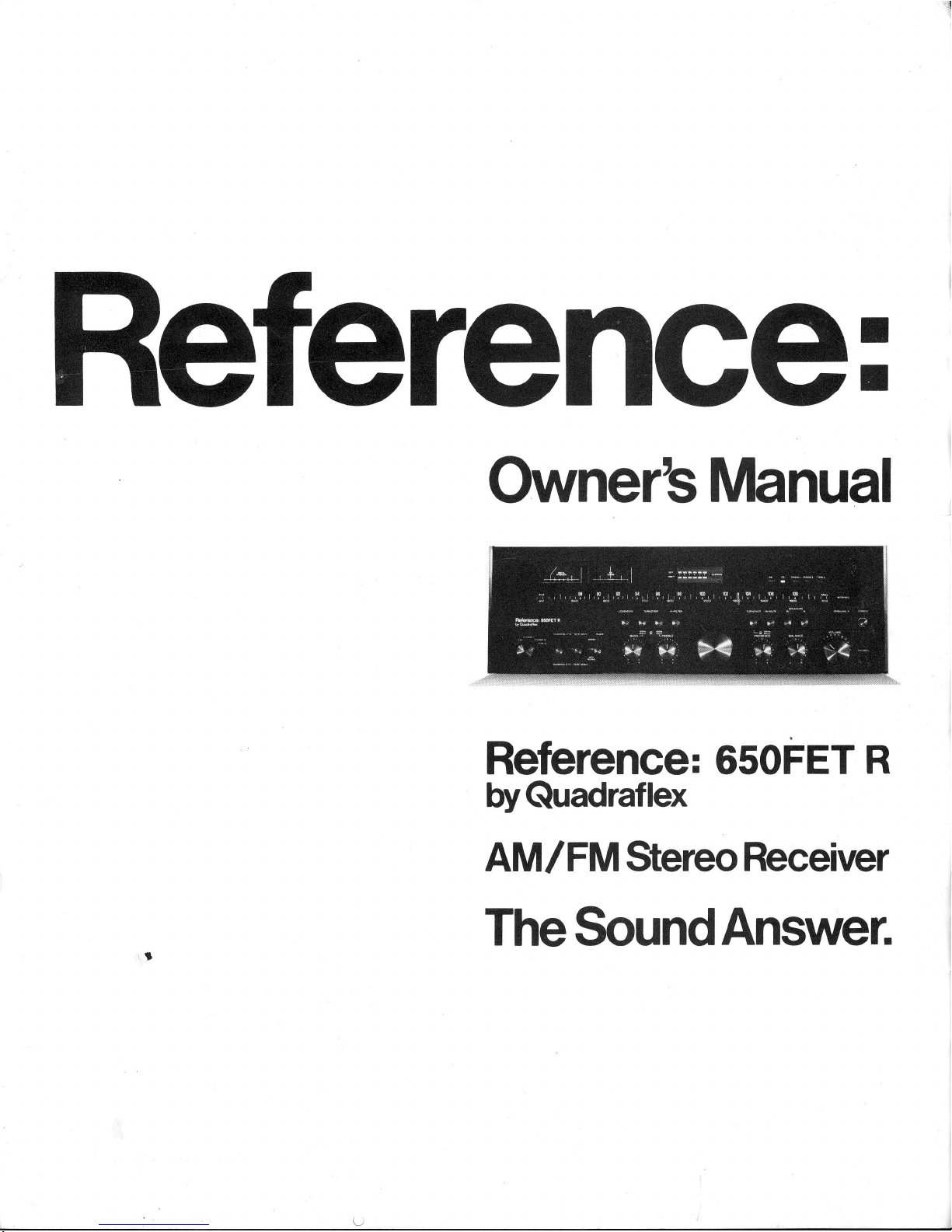
Referehce: osoFET
R
byQuadraflex
AMIFM
StereoReceiver
TheSoundAnswer.
Page 2
Referehce: 65oFET
R
by
Quadraflex
AM / FM
StereoReceiver
Cong
ratu
lations !
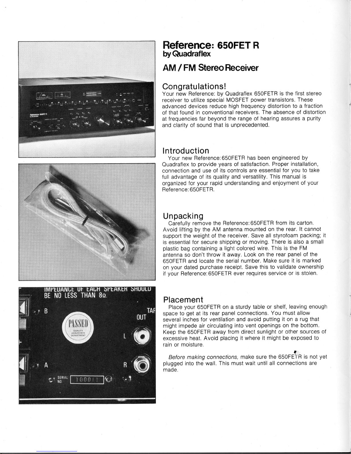
Your
new Reference: by Quadraflex
650FETR
is the first stereo
receiver to utilize special
MOSFET
power
transistors.
These
advanced
devices
reduce
high frequency distortion
to a fraction
of
that found
in
conventional
receivers. The absence of distortion
at
frequencies far beyond
the range of
hearing
assures
a
purity
and clarity
of sound that
is unprecedented.
lntroduction
Your new Reference:650FETR
has
been engineered
by
Quadraflex
to
provide years
of satisfaction.
Proper
installation,
connection and
use of
its
controls
are essential
for
you
to take
full
advantage
of
its
quality
and
versatility. This manual
is
organized
for
your
rapid understanding and
enjoyment of
your
Reference: 650FETR.
U
n
packi
ng
Carefully
remove the
Reference:650FETR
from
its
carton.
Avoid
lifting by
the AM antenna
mounted on the
rear. lt cannot
support
the
weight
of
the
receiver. Save all styrofoam
packing;
it
is
essential
for
secure
shipping or
moving.
There is also a small
plastic
bag containing
a
light
colored
wire.
This is the FM
antenna
so
don't throw
it
away.
Look on
the rear
panel
of
the
650FETR
and
locate the serial
number.
Make sure it
is marked
on
your
dated
purchase
receipt. Save
this to validate ownership
if
your
Reference:650FETR
ever
requires service or
is stolen.
Placement
Place
your
650FETR
on a sturdy
table or shelf,
leaving enough
space to
get
at
its rear
panel
connections.
You
must
allow
several
inches for
ventilation
and
avoid
putting
it on a
rug that
might impede air circulating
into vent openings on
the bottom.
Keep the 650FETR
away
from direct sunlight
or other sources
of
excessive
heat. Avoid
placing
it where
it might
be
exposed to
rain or
moisture.
Before making connections.
make sure the 65OFE1R
is not
yet
plugged
into the
wall. This
must wait until all connections
are
made.
Page 3
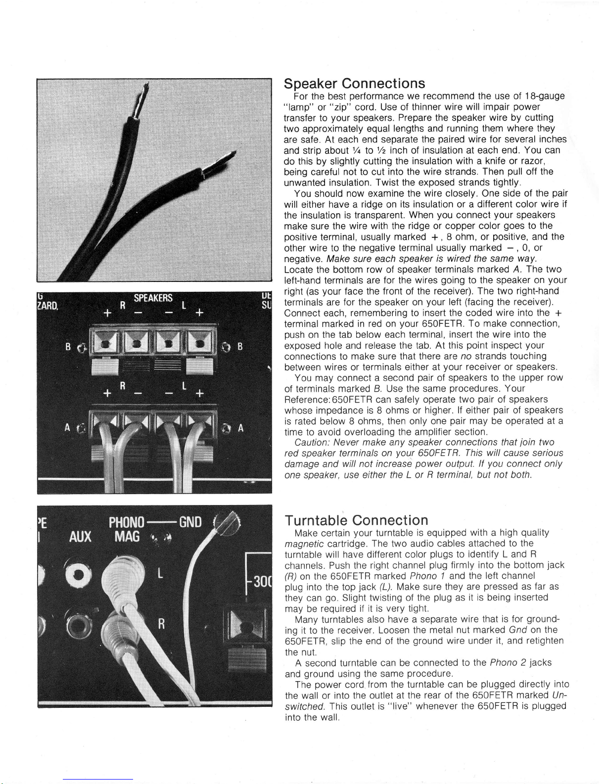
Speaker Connections
For
the
best
performance
we recommend the use of
1B-gauge
"lamp"
or
"zip"
cord. Use
of thinner
wire will impair
power
transfer
to
your
speakers.
Prepare the speaker
wire
by cutting
two approximately
equal lengths and
running them where they
are safe.
At
each
end separate
the
paired
wire for several
inches
and strip aboul1/t
to
% inch
of
insulation at each end.
You can
do this by slightly
cutting the
insulation with a knife or
razor,
being
careful not to cut
into the wire
strands.
Then
pull
off the
unwanted
insulation. Twist the exposed strands
tightly.
You
should
now examine the
wire closely. One side of the
pair
will
either
have a
ridge
on
its insulation or a different color
wire if
the insulation
is transparent. When
you
connect
your
speakers
make sure
the wire with the
ridge or copper color
goes
to the
positive
terminal, usually
marked
+,
8 ohm, or
positive,
and
the
other
wire to the
negative
terminal
usually marked
-
,
0, or
negative. Make sure each
speaker
is wired
the same
way.
Locate the bottom
row of speaker terminals
marked A.
The
two
left-hand terminals are
for the wires
going
to the
speaker on
yout'
right
(as your
face the front of the receiver).
The two right-hand
terminals are
for the speaker on
your
left
(facing
the
receiver).
Connect
each,
remembering
to
insert the coded
wire into the
+
terminal
marked in red on
your
650FETR.
To make connection,
push
on
the tab below each
terminal, insert the
wire into
the
exposed
hole
and
release the tab. At this
point
inspect
your
connections
to make sure that there are
no strands touching
between
wires
or terminals
either at
your
receiver
or
speakers.
You may connect a second
pair
of speakers to the upper
row
of terminals
marked B. Use the same
procedures.
Your
Reference:650FETR can safely operate
two
pair
of speakers
whose impedance
is
8 ohms or
higher.
lf
either
pair
of speakers
is rated
below
8 ohms, then only
one
pair
may be operated at a
time to avoid overloading
the amplifier section.
Caution:
Never make any speaker connections that
join
two
red speaker
terminals on
your
650FETR.
This willcause serious
damage
and
will not increase
power
output.
lf
you
connect only
one
speaker, use
either the L or R terminal, but
not
both.
Turntable
Connection
Make certain
your
turntable
is equipped
with a high
quality
magnetic cartridge.
The two audio cables
attached to the
turntable
will
have
different
color
plugs
to identify L and
R
channels.
Push the
right channel
plug
firmly into the bottom
jack
(R)
on the 650FETR
marked Phono 7 and
the left channel
plug
into the top
jack
(L).
Make sure
they are
pressed
as
far as
they can
go.
Slight twisting
of the
plug
as
it is being
inserted
may be
required if it
is very tight.
Many turntables
also
have a separate
wire that is for
ground-
ing it to the
receiver. Loosen the
metal nut
marked
Gnd on
the
650FETR,
slip
the end of the
ground
wire
under
it,
and
retighten
the nut.
A
second
turntable can
be connected
to the Phono 2
jacks
and
ground
using
the same
procedure.
The
power
cord
from
the turntable
can be
plugged
directly into
the wall or
into the outlet at
the rear of the 650FETR
marked Un-
switched.
This outlet
is
"live"
whenever the 650FETR
is
plugged
into the
wall.
Page 4

Antenna Connections
Proper anienna
placement
is essential for
good
FM reception.
In most
areas
the
T-shaped
"folded
dipole"
wire supplied
with
your
650FETR
is
adequate.
lnsert the two bare ends
into the
Antenna terminals
with
the
red tabs marked
300 ohms.
Stretch
out the top section of
the
"T";
you
may find that
you
will have to
reposition it later for optimum
reception. In
difficult
reception
areas
it may be necessary
to
utilize an outdoor antenna
instead.
Your 650FETR can often
"share"
with a TV antenna by using an
inexpensive
antenna
splitter or 2 set-coupler, available
from
your
dealer.
Connections
made from flat wire are made at the
red
terminals. So are
connections
made from the flat wire coming
out
of a
matching
transformer
if
your
antenna
uses rounded
coaxial-type
cable.
You may make direct coaxial cable connections
by separating
the inner wire
from its
surrounding
braided shield wire. The
stripped
inner wire
attaches
to the right
hand red terminal; the
outer braid
is
twisted
firmly
and
inserted in the adjacent black
terminal marked Gnd.
A ferrite bar
AM
antenna
is
attached
to the rear of
your
Reference:650FETR. For adequate
reception
you
must swing
it
away
from the
chassis,
clear of wires and cords.
lt may require
repositioning depending on the direction a
station is broadcasting
from.
Better
reception
of
distant AM stations
is
possible
if
you
connect a single
long wire to the AM antenna terminal.
This wire
should
be 20 to
50
feet in length
and
run mostly horizontally.
Connecting
A
Tape Deck
The Reference:650FETR
has two separate tape
monitor
circuits.
You may connect two tape decks, or one
tape deck to
either circuit.
The line lnputs to
your
tape deck
plug
into either
set of lape
out
jacks
on the
650FETR. The output
jacks
on the
tape deck connect
to the tape rn
jacks
on the 650FETR.
Make
certain
that L and B connections are
consistent
for Tape
Out and
Tape
ln
so channels
are not
reversed from recording to
playback.
A third tape deck
may be used for
playback
only by
connecting
its
output
to the fape 3
jacks
on the 650FETR.
You
may
plug your
tape deck's
power
cord either
directly
into
the
wall
or
into the Swifched
AC
outlet on
vour
Reference:650FETR
Connecting
Other Components
f he Tape ln or
Tape
3
jacks
may be used
with
sources other
than a
tape deck as
long
as
they
have
similar signal
levels. The
audio output of
a television or short
wave tuner are
just
two
possibilities.
You
should
consult
your
dealer
if
you
are
considering
connecting such equipment.
Connection
Summary
At this
point
double-check all
your
connections to
make sure
all
plugs
are
inserted
firmly and speaker
wires do not
have
any
it
I
Page 5

touching strands at
either end. Make
sure the
power
switch is
in
its
off
position
and
plug
the Reference:650FETR
into a nearby
wall
outlet or
extension cord.
Whenever
you
move
the receiver or change
connections
on
the back
panel
make
certain
the
power
is
switched ofl.
Operating the Reference:650FETR
The front
panel
controls of
your
Reference
receiver
provide
tremendous flexibility when
used together.
Please
read this
section so
that
you
will understand how to
best use them. Before
starting, turn the volume
control counterclockwise to its minimum
oosition.
To
Receive
FM Broadcasts
1.
Set the far left
selector knob
to the FM
oosition.
2.
Set
the Tape
Mon
switch to Source
and the Mode
switch to
Sfereo.
3. Set Bass, Treble,
Presence,
and Balance
knobs
at their
center
(12
o'clock) settings.
4. Push
the
Speaker A button.
5.
Release
the Loudness
and FM Mufe
buttons.
6. Release
the Hl Fll/er
button.
Now
push
the
power
button
and slowly
advance
the Volume
knob. Tune
to the
desired station
until the Tuning
meter is in
its
center
position.
A
quick
check
of
the
stations
you
like
may
indicate
the need to reposition
the FM
antenna.
The
Signal Strength meter
can
be used tp
check the
effectiveness
of antenna
position.
lts needle
should read
steadily
as
far
to the right
as
possible.
With insufficient
signal
strength
readings
you
will not
be
able to receive
clear broadcasts.
When
you
reach
a station
broadcasting in
stereo the red
stereo
indicator
at the
right
side
of the dial scale
will illuminate.
Push
the FM Mute
switch
to reduce
noise
and
"hiss"
between
stations. The
muting
circuit blocks
all signals below
a certain
strength, including
weak
stations. Release
the FM Mute
button to
receive
these broadcasts.
The
Reference:650FETR
incorporates
a soecial MPX Blend
position
on
its
Mode
switch. This effectively
reduces
background
noise on many
broadcasts without
inhibiting
high frequency
response.
lt works
by altering the
separation
characteristics
of
the stereo multiplex
circuit, reducing
its
vulnerability
to noise.
lf
the signal is
still too noisy it may
be necessary
to
set the
Mode
switch to the Mono
position
where
the
650FETR is least
susceptible to noise. Further
experimentation
with
antenna
position
may
also be required
to receive
certain
stations.
To Receive
AM
Broadcasts
The
procedure
is
similar with
several
significant exceptions.
Set the selector knob
to the AM
position.
Tune
stations
so that
the Tuning
meter deflects
to
its
highest rather
than
center
position.
There is no
muting for AM.
Page 6

Phono Operation
Set the selector
to Phono 1 or
Phono 2 depending on
which
one
you
have
attached
your
turntable
to. Make sure
your
turntable
is located
far
enough away
from
your
speakers
to
prevent
feedback.
Tape Deck Operation-
Playback
The Tape
Mon
switch
normally controls selection
of
playback
for
two decks.
lf
your
deck
is a three-head design
(usually
open-
reel), the
fape
position
allows
you
to
hear the tape deck's output
whether it is in its
record or
playback
mode.
Switching
the fape
Mon
lever
to
its fape 1 or
Tape 2
position
overrides
the
selector
switch
for the sound
you
will
hear. lf no
tape
deck is
attached
to
either the
Tape 1 or Tape
2
position,
no sound
will
be
heard.
Tape
Deck Operation-Recording
Set
the selector
for the source
you
wish to
record. Adjust
recording controls on
your
tape deck according
to the
manufacturer's
instructions.
The recording will
not
be affected
by
the 650FETR's
settings oI
Volume,
Balance, Loudness,
Hi Filter
or any
of the
tone controls.
You can
quickly
check
to see
that the deck
is receiving
the
proper
signal
by switching
the
fape Mon
lever
to
its appropriate
fape
position.
Copying
Tapes
Copying
tapes requires two tape
decks. Your
Reference:650FETR
is
equipped
with special
Dubbing circuits
which allow
decks to copy
from either
one
to the other
independent of
the selector switch.
This means that
you
can
listen to any source
while the decks are copying.
This
is
done by
setting
Ihe Dubbing
switch
in
the
1
>2 position
if
you
wish
to
play
a tape on
Deck 1 and copy
it
on
Deck 2. Use the
2>'l
position
to
reverse the
procedure.
To listen to either deck at any
time use the
fape Mon switch.
Thus
you
have the choice of
listening to the deck
playing,
the deck
recording, or an entirely
separate
source
without interfering with the
recording.
Adjusting Tone
The
Reference:650FETR receiver
has
controls
to
adjust
bass,
treble, and
/oudness compensation.
The bass and treble controls
have
no affect on
the sound in their center
(12
o'clock)
position.
These controls should be set
to taste. There are detents at each
2 dB
increment for easily repeatable settings.
Avoid turning the
bass
all
the way up at
high volume. This may distort the sound
and damage
your
loudspeakers.
The Reference:650FETR
has
an additional
Presence control to
boost or cut critical
midrange frequencies.
lt is
especially
useful
to
isolate a solo
voice,
piano, guitar,
etc. and
make it more
or
Page 7

less
prominent.
lt
also
helps
adjust to
deficiencies in
your
loudspeakers
or
listening
environment.
Further flexibility
is
provided
by the Turnover
buttons. These
alter the frequencies
which
the
bass and
treble
controls
affect.
The
outer
position
of each
selects
control
over freouencies
closer to the
midrange where
your
ears
are more
sensitive;
making
the effects
of the
bass
and treble
controls more
noticeable.
The
inner
position
selects more
extreme
freouencies
where
your
ears are less
sensitive
and the
effect is more
subtle.
The Loudness
button
activates
a circuit that
slightly
boosts
extreme
bass
and treble frequencies.
Because
your
ears
are
less
sensitive to these
extremes
at
low volumes,
this
circuit
compensates
so
that
you
hear
all the music. Avoid
excessive
bass control
boost when
the Loudness
button is
oushed.
The
Hi Filter reduces
the
high frequency
content
of the sound.
It will
reduce
"hiss"
in
tapes
and broadcasts.
Use only
as
needed.
The
Balance
control
adjusts relative
volurhe
between
the Right
and
Left channels.
Use
it if
you
sit closer to
one speaker
than
the
other so that
the sound
source is
"centered't.
H
ead
phones
This is
the output
for stereo headphones.
Plug
in
your
headphones
for
private
listening;
you
can elect to have
speakers
on
also
if
you
wish. However,
unplug headphones
when
you
aren't using them; high
power
surges could
damage
them.
Overload Indicator
The Reference:650FETR
has
a small red
LED located
next
lo
the
power
button. lt
lights
to
indicate
a short-circuit
or overload
condition
and the sound
shuts
off. This
protects
critical circuit
components
from
damage. lf
the LED lights,
turn
off the
power
and
check all
your
speaker
connections.
Normal
operation
may
be resumed
by waiting
15 seconds
before.turning
power
on again.
Power
Meters
The Reference:650FETR
has
two
unique
9-position LED
power
indicators.
They
enable
you
to relate
the
power
function
of the
amplifier
sections
lo
your
desired listening
level.
The last
section
of these indicators
marked
Clipping
will flash
when
the amplifier
approaches its maximum
undistorted
capacity. lf the last
LED's
stay lit
you
are operating
at or
beyond the timits
of the 650FETR.
This
could cause
sustained
speaker
damage
from
overload.
Page 8

Tuning
Dial
Loudness
Switch
Hi-Filter
Switch
Power
Switch
AM/FM
Signal
Strength
Meter
FM
Center
Tuning
Meter
Tone
Turnover
Selector
Switches
Tone
Controls
LED
Power
lndicator
I
Tuning
Knob
FN/
Source
Station
Muting
Indicator
Indicator
Switch
Lights
FM
Stereo
lndicator
Speaker Overload
Selectors Indicator
(Do
not
use
as
handle.)
earjnce
I
u",rtr.l rulopnon"
Control
I
Control
Il
Output
rl
Main/Remote
I
I
Source
Selector
AC
Power
Cord
I
Tr na
Dubbing
Switch
I
Mode
Switch
Monitor
Switch
ll
I
Presence
I
Control
Presence
Turnover
Selector
Switch
Unswitched
AC
Outlet
Femote
Speaker
Outputs
I
Main
Speaker
Outputs
Inputs
Deck
2
In
pu
ts
Deck
1
Phono
2 Phono
AM
Inputs
Ground
Antenna
ll
I
Swrtched
Fuse Outlet
Tape
Tape
Tape
| |
Outputs
Outputs
Inputs Phono
1 Antenna
Deck 2
Deck 1
Deck 3 Inputs
Terminals
Page 9

Block
Diagram
Speaker A
Reminder
Get
into
the
habit
of turning
down the volume control
on
your
Reference:650FETR
when
you
turn
your
system on or
off.
This
eliminates the
possibility
of inadvertently
damaging
your
speakers if the
power
is
switched on with the volume
control
advanced.
Troubleshooting
Usually
problems
that
occur are
not
the fault of
your
Reference receiver
and are easily
cured.
lf
you
cannot solve
a
problem
in
the manner described
below, consult
your
Reference
dealer.
No
sound and the receiver
does
not light
up.
Make
sure the
Reference:650FETR
is
plugged
into a working
AC outlet
or extension cord. Check the AC line fuse
at the back
of the
receiver.
lf the fuse is
blown, replace it
only
with
the same
type.
A larger fuse
will create internal
damage to the
circuit. lf
the new fuse
blows again, consult
your
dealer.
The receiver
lights but
produces
no sound.
Make sure the fape Mon
lever is in
the Source
position.
Speakers switched on.lt
Overload light is
on, switch
power
off,
check all connections
and
wait 15
seconds_ before
turning on.
Make sure there is
adequate ventilation
to
prevent
overheating. lf
light
comes on again,
you
may have
a shorted speaker
or
section
of speaker wire.
No
sound
from
one channel.
Recheck
connections
and Balance control. lf
this occurs
only
with Phono
or a tape deck, switch
the L and R input leads. lf
the
sound then comes out
of
the
other channel,
you
can be certain
the
problem
is with
the source or its
cable and
not
your
receiver.
Poor bass response.
Check speaker
phasing
by switching to mono
and
back to
stereo.
lf
the bass is weaker in
mono, turn
off the
power
and
reverse
the
+ and
-
wires tor
one soeaker
onlv.
ilum sound.
Make sure
audio cable
plugs
are
inserted
firmly
and
that
the
phono ground
wire is
attached to the receiver.
Occasionally
removing
the
ground
wire will
eliminated hum.
Move receiver
away
from TV
set or fluorescent light.
Poor reception
Almost
always
the fault
of the antenna.
Dense urban
and
hilly
areas
present
a
greater
challenge
from
multipath
or
reflected
signals
like
those which cause
"ghosts"
with TV reception.
Your
dealer can
provide
assistance.
Cleaning.
Use a slightly damp cloth. Avoid
use of any
cleaners or
solvents; they might
scratch the
panel
or cloud the
dial
window.
Page 10

Reference: 650FETR
Performance Data
Amplifier Section:
Power Output: 65
watts continuous
power per
channel
minimum
RMS,
both channels driven
into 8 ohms
with no more than 0.1 %
total
harmonic distortion.
(1
8.13
dBw)
Frequency
Response at
1 watt: 5-65,000
Hz t .5 dB
Total Harmonic
Distortion at
1 watt: .01 %
lM Distortion al
1 watt: .02%
Crosstalk
at 1 kHz:
-
60 dB
Output
Type: MOSFET
Preamplif ier Section:
Signal-toNoise
Ratio: Phono
1,2 80 dB;
Tape Mon 1,2 85 dB;
Tape
3 85
dB
lnput
Sensitivity:
Phono 1
,2
2.0 mV; Tape
Mon 1 , 2 160 mV;
Tape 3
160
mV
Phono Overload: 200
mV
RIAA Equalization:
t
.25
dB
Tone Control
Range: Bass
t 10 dB
at
50 Hz
with 150 Hz turnover
t
10
dB at
100 Hz with 300
Hz turnover
Treble t 10 dB at 20 kHz
with 6 kHz turnover
t
10
dB at 10 kHz with 3 kHz turnover
Presence t 6 dB at 800
Hz or
'l
.5'kHz turnover
Loudness
Contour
(at
-30
dB):
+8
dB at
100 Hz;
+6
dB at 20
kHz
.High
Filter: - 3 dB at
10 kHz
FM Section:
IHF Sensitivity:
for 30 dB
quieting:
mono 1.79V
(9.8
dB0; stereo
a.2pV
(17.7
dBf)
for 50 dB
quieting:
mono 2.69V
(1
3.5
dBf); stereo 34gV
(35.9
dBf)
Channel
Seoaration at
1 kHz: without
MPX Blend 44 dB;
with MPX Blend 24
dB
.
THD:
mono .1
o/o;
stereo .15%
Signal-to-Noise
Ratio: 72 dB
Capture
Ratio: 1 dB
Alternate Channel Selectivity:
72 dB
lF
Response Ratio: 95 dB
lmage
Rejection Ratio: 60 dB
Muting Threshold: 8
gV
(23.3
dBf)
AM Section:
IHF Sensitivity:
200
gvlm
THD: .50/o
Signal-to'Noise
Ratio: 50
dB
lmage Rejection Ratio: 50 dB
Reference: by
Quadraflex
Limited Warranty
Your Beference: by Quadraflex
receiver is
covered by a
limited
warranty against defects
in materials
and
workmanship for
a
period
of two
years
from
the
date of
purchase.
Reference warranty repair will be
performed
only
when
your purchase
receipt is shown
as
proof
of
ownership. Defective
parts
will
be
repaired
or
replaced without
charge
if
this Reference receiver is returned to
your
dealer's store, as shown on
your purchase
receipt,
or to any branch of
that
store
where, in
all cases,
authorized service will be available. Check the
yellow pages
or white
pages
of
your
telephone directory for the location nearest
you.
lf
additional assistance
is reouired.
olease
write
to
Reference
at the address
provided
below describing the
malfunction. Reference will
send directions
in writing.
Charges
for
unauthorized service and transportation costs are
not
reimbursable under this
warranty. Any
damage or defect
resulting trom
unauthorized
parts
or services is not covered by this wananty. Any
services
performed
by other than a dealer authorized to
perform
such
services are not reimbursable under this warranty.
This warranty
becomes
void if the
serial
number is
defaced or
removed,
or the
product
has
been damaged by alteration, misuse, accident or
neglect. THE WARRANTOF ASSUMES NO LIABILITY FOR PROPERTY
DAMAGE OR
ANY
ATHER
INCIDENTAL
OR CONSEOUENTIAL
DAMAGE
WHATSOEVER
WHICH MAY RESUTT FROM THE FAILURE
OF
THIS
PRODUCT. Any and all warranties ot MERCHANTABILITY and ot
F/INESS implied by
law
are
limited
to the duration of this expressed
limited warranty.
Some states
do not
allow
limitations
on
how long
an
implied warranty
lasts,
so the above
limitations may not
apply to
you.
Some states do
not
allow the exclusiori or
limitation
of incidental or consequential damages,
so the
above
limitation
or
exclusion may not
apply
to
you.
This warranty
gives you
specific
legal rights
and
you
may
also
have
other
rights which vary from
state to state.
Service
Manager
Reference: by Quadraflex
CBS
Inc.
1 301 65th Street
Emeryville, California 94608
Referehce:
by
Quadraflex
CBS
Inc.
1301
65th Street
Emeryville, California 94608
Printed in
USA
,.-
1978
 Loading...