

Quadra-Fire YOSEMITE-MBK, YOSEMITE-PMH Owner's Manual
R
Yosemite
O-T L
Tested and
Listed by
Portland
Oregon USA
OMNI-Test Laboratories, Inc.
C
US
Non-Catalytic, Front/Side Load, Wood Heater
Owner’s Manual
Installation and Operation
Models:
YOSEMITE-MBK
YOSEMITE-PMH
DO NOT DISCARD THIS MANUAL
•
Important operating
and maintenance
instructions included.
• Read, understand and
follow these instructions
for safe installation and
operation.
WARNING
If the information in these
instructions is not followed
exactly, a re may result causing
property damage, personal injury,
or death.
• Do not store or use gasoline or other
ammable vapors and liquids in the vicinity
of this or any other appliance.
• Do not overre - If heater or chimney
connector glows, you are overring.
Overring will void your warranty.
• Comply with all minimum clearances to
combustibles as specied. Failure to comply
may cause house re.
WARNING
Fire Risk.
For use with solid wood fuel only.
Other fuels may overre and generate
poisonous gases (i.e. carbon monoxide).
Installation and service of this appliance should
be performed by qualied personnel. Hearth &
Home Technologies recommends NFI certied
professionals, or technicians supervised by an
NFI certied professional.
CAUTION
Hot glass will cause burns.
• Do not touch glass until it is cooled
• NEVER allow children to touch glass
• Keep children away
• CAREFULLY SUPERVISE children in same room
as replace.
• Alert children and adults to hazards of high
temperatures.
High temperatures may ignite clothing or other
ammable materials.
• Keep clothing, furniture, draperies and other
ammable materials away.
To obtain a French translation of this manual, please
contact your dealer or visit www.quadrare.com
Pour obtenir une traduction française de ce manuel,
s’il vous plaît contacter votre revendeur ou visitez
www.quadrare.com
• Leave this manual with
party responsible for
use and operation.
WARNING
HOT SURFACES!
Glass and other surfaces are
hot during operation AND
cool down.
NOTE
DO NOT
DISCARD
www.quadrare.com
7004-187I
December 20, 2011
Yosemite Wood Stove
R
and Welcome to the Quadra-Fire Family!
Hearth & Home Technologies welcomes you to our tradition of
excellence! In choosing a Quadra-Fire appliance, you have our
assurance of commitment to quality, durability, and performance.
This commitment begins with our research of the market, including
‘Voice of the Customer’ contacts, ensuring we make products that
will satisfy your needs. Our Research and Development facility
then employs the world’s most advanced technology to achieve
the optimum operation of our stoves, inserts and replaces. And
NOTE: Clearances may only be reduced by means
approved by the regulatory authority having jurisdiction
LABEL IS LOCATED ON THE BACK OF THE STOVE
HOT WHILE IN OPERATION DO NOT TOUCH, KEEP CHILDREN AND CLOTHING AWAY. CONTACT MAY CAUSE SKIN
CAUTION:
Tested and
Listed by
C
OMNI-Test Laboratories, Inc.
LISTED ROOM HEATER, SOLID FUEL TYPE. ALSO FOR USE IN MOBILE
HOMES. (UM) 84-HUD .
PREVENT HOUSE FIRES
Install and use only in accordance with manufacturer's
installation and operating instructions. Contact local building or
fire officials about restrictions and installation inspections in
your area. Do not obstruct the space beneath heater.
WARNING - For Mobile Homes:
room. An outside combustion air inlet must be provided and
unrestricted while unit is in use. The structural integrity of the
mobile home floor, ceiling and walls must be maintained. The
stove needs to be properly grounded to the frame of the mobile
home. Components required for m obile home installation:
Outside Air Kit, Part Number 831-1780.
Refer to manufacturer's instructions and local codes for
precautions required for passing chimney through a
combustible wall or ceiling and maximum offsets.
nspect and clean chimney frequently - Under Certain Conditions of
I
Use, Creosote Buildup May Occur Rapidly.
Do not connect this unit to a chimney serving another
appliance.
Optional Components: Optional Blower, Part 831-1701.
Electrical Rating: 115 VAC, 1.2 Amps, 60 Hz.
Route power cord away from unit. Do not route cord under or
in front of appliance.
DANGER: Risk of electrical shock. Disconnect power supply
before servicing.
Replace glass only with 5mm ceramic available from your dealer.
Do not use grate or elevate fire. Build wood fire directly on
firebrick.
Do not overfire - if heater or chimney connector glows, you are
overfiring.
Operate only with the fuel loading door closed. Open only to
add fuel to the fire.
FLOOR PROTECTION*:
Floor protector must be
non-combustible material or
equivalent, extending beneath
heater and to front/sides/rear as
indicated on the diagram.
Exception: Non-combustible floor
protections must extend beneath
the flue pipe when installed with
horizontal venting and extend 2"
(51mm) beyond each side.
*In Canada: Must be minimum 18"(450mm) in front of both fuel loading
Mfg by
1445 N. Highway, Colville, WA 99114
www.quadrafire.com
Report: #061-S-54-2
"For Use with Solid Wood Fuel Only"
Do not install in a sleeping
Both fuel loading doors accessible
Fuel loading doors
8"
(203mm)
doors and 8" (200mm) on both sides and back.
BURNS. KEEP FURNISHINGS AND OTHER COMBUSTIBLE MATERIAL FAR AWAY FROM THE APPLIANCE. SEE
NAMEPLATE AND INSTRUCTIONS.
Portland
O-T L
Oregon USA
US
UL 1482, UL737, ULC S627-00
SINGLE WALL:
HT Class "A" chimney, suitable for use with solid fuels, or a masonry chimney, and the referenced clearances.
DOUBLE WALL: Six inch (6") (152mm) diameter, listed double wall air insulated connector pipe with listed factory-built UL103 HT Class
"A" chimney, or a masonry chimney and the referenced clearances.
*In Canada must comply with Standard CAN/ULC-S629-M87 for the 650 degree Factory-built chimneys.
MOBILE HOME: Use double wall pipe by Dura-Vent DVL, Selkirk Metalbestos DS or Security DL double wall connector pipe. Must be
equipped with a spark arrestor. Apply double wall clearances below when installing unit.
MINIMUM CLEARANCES TO COMBUSTIBLE MATERIALS: In Inches & (Millimeters)
NOTE: All "A" , "C" and "F" Dimensions are to the inside diameter of the flue collar.
TOP ENT ERTICAL
Single Wall-USA 12.5(316) 9(229) 19.5(495) 25.5(648) 10(254) 16 (406) 14(356) 16(406) 18.5(470) 20.5(521) 59(1499) N/A
Single Wall-Canada 12.5(316) 9(229) 19.5(495) 27.5(669) 10(254) 18 (457) 14(356) 18(457) 18.5(470) 22.5(572) 59(1499) N/A
Double Wall- USA 10.5(267) 7(178) 19.5(495) 25.5(648) 10(254) 16(406) 7 (178) 16(406) 11.5(292) 20.5(521) 59(1499) N/A
Double Wall-Canada 1
TESTED TO:
Six inch (6") (152mm) diameter, minimum 24 MSG black or blued steel connector pipe, with a listed factory-built UL103
AB C1 C2* D1 D2* E1 E2* F1 F2* GH
0.5(267) 7(178) 19.5(495) 27.5(699) 10(254) 18(457) 7 (178) 18(457) 11.5(292) 22.5(572) 59(1499) N/A
R
YOSEMITE
VENT SPECIFICATIONS:
HORIZONTAL WITH MINIMUM 2FT (609mm) VERTICAL OFF STOVE TO P
Single Wall-USA 13.5(343) 10(254) 19.5(495) 25.5(648) 10(254) 16 (406) N/A N/A N/A N/A 59(1499) 18**
Single Wall-Canada 13.5(343) 10(254) 19.5(495) 27.5(699) 10(254) 18 (457) N/A N/A N/A N/A 59(1499) 18**
Double Wall-USA 11.5(330) 8(203) 19.5(495) 25.5(648) 10(254) 16(406) N/A N/A N/A N/A 59(1499) 18**
Double Wall-Canada 11.5(330) 8(203) 19.5(495) 27.5(699) 10(254) 18(457) N/A N/A N/A N/A 59(1499) 18**
**NFPA MINIMUM CLEARANCE - NOT TESTED
8"(203mm)
Side
Front
Minimum 16"
(406mm) from
fuel loading
44-1/2"(1130mm) Minimum
2010 2011 2012 Jan. Feb. Mar. Apr. May June July Aug. Sept. Oct. Nov. Dec.
Side fuel loading door locked shut
36-11/16"
door
USA
DO NOT REMOVE THIS LABEL
Front Fuel
loading door
(932mm)
Minimum
16" (406mm) from fuel
SAMPLE
loading door
33"(838mm) Minimum
(203mm)
36-11/16"
8"
USA
SEE MANUAL FOR OTHER CONFIGURATIONS
B
A
(932mm)
Minimum
C1
D1
Non-fuel
door side
Made in U.S.A.
yet we are old-fashioned when it comes to craftsmanship. Each
unit is meticulously fabricated and gold and nickel surfaces are
hand-nished for lasting beauty and enjoyment. Our pledge to
quality is completed as each model undergoes a quality control
inspection.
We wish you and your family many years of enjoyment in the
warmth and comfort of your hearth appliance. Thank you for
choosing Quadra-Fire.
007
SERIAL NO.
Serial Number
Model Name
Testing Lab &
Report Number
C2
D2
Fuel Door
side
Non-fuel
door side
E1
F1
F2
E2
Fuel door
side
U.S. ENVIRONMENTAL PROTECTION AGENCY -
Certified to comply with July 1990 particulate emission
standards.
G
7004-188
H
Mfg. Date
Page 2
7004-187I
December 20, 2011
R
Yosemite Wood Stove
Safety Alert Key:
• DANGER! Indicates a hazardous situation which, if not avoided will result in death or serious injury.
• WARNING! Indicates a hazardous situation which, if not avoided could result in death or serious injury.
• CAUTION! Indicates a hazardous situation which, if not avoided, could result in minor or moderate injury.
• NOTICE: Indicates practices which may cause damage to the replace or to property.
TABLE OF CONTENTS
Section 1: Listing and Code Approvals
A. Appliance Certications ......................4
B. Mobile Home Approved ......................4
C. Glass Specications ............................4
D. BTU & Efciency Specications ..........4
Section 2: Getting Started
A. Design, Installation & Location
Considerations ....................................5
B. Fire Safety ..........................................5
C. Negative Pressure ..............................6
D. Flue Draft Considerations ...................7
E. Venting Systems .................................7
F. Tools and Supplies Needed................7
G. Inspect Appliance & Components
and Pre-Burn Check List.....................7
H. Typical Stove System .........................8
Section 3: Dimensions & Clearances
A. Appliance Dimensions ........................9
B. Clearances to Combustibles ...............10
Section 4: Installation Consideration
A. Hearth Requirements .........................11-12
B. Reversible Flue Collar ........................13
C. Horizontal Flue Heat Shield ................13
D. Leg Leveling System ..........................14
E. Side Fuel Loading Door Locking
Mechanism .........................................14
F. Outside Air ..........................................15
G. Optional Blower Installation ................15
Section 5: Chimney Requirements
A. Venting Components ..........................16
B. Chimney Systems ...............................16-19
C. Installing Chimney Components .........19
D. Chimney Termination Requirements ..20
E. 2-10-3 Rule .......................................... 20
Section 6: Mobile Home ...............................21
Section 7: Appliance Set-Up
A. Door Handle Assembly .......................22
B. Blower Speed Adjustment ..................22
Section 8: Operating Instructions
A. Overring Your Appliance ...................23
B. Wood Selection & Storage ..................23-24
C. Burning Process ..................................24-25
D. Combustible / Non-Combustible
Materials .............................................25
E. Air Controls .........................................25
F. Heat Output Settings ...........................26
G. Burn Rates ..........................................26
H Building A Fire .....................................26
I. Blower Operating Instructions .............27
J. Opacity (Smoke) ................................. 27
K. Clear Space ........................................28
L. Frequently Asked Questions ...............28
M. Correct Bafe & Blanket Position ........29
Section 9: Maintaining & Servicing Appliance
A. General Maintenance & Cleaning .......30-31
B. Appliance Inspection - Routine ........... 32
C. Firebrick Inspection & Replacement ...32
D. Glass Replacement .............................32
E. Bafe Removal & Installation .............. 33
F. Quick Reference Maintenance Guide . 34
Section 10: Troubleshooting ........................35
Section 11: Reference Material
A. Exploded Drawings .............................36
B. Service Parts & Accessories............... 37-40
C. Service & Maintenance Log ................ 41
D. Warranty Policy ...................................42-43
E. Contact Information .............................44
7004-187I December 20, 2011
Page 3
Yosemite Wood Stove
Listing and Code Approvals
1
R
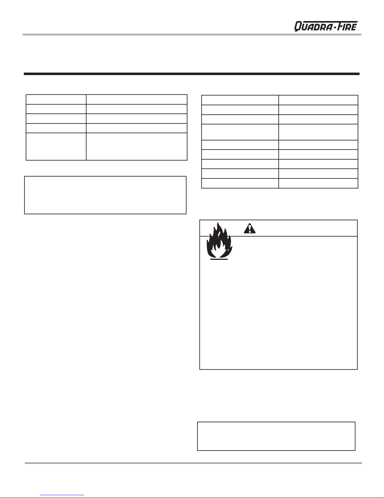
A. Appliance Certication
Model:
Laboratory: OMNI Test Laboratories, Inc.
Report No & Date:
Type:
Standard: UL1482, UL737, ULC S627-00
NOTE: This installation must conform with local codes. In the
absence of local codes you must comply with the UL1482, UL737,
(UM) 84-HUD and NPFA211 in the U.S.A. and the ULC S627-00
and CAN/CSA-B365 Installation Codes in Canada.
The Quadra-Fire Yosemite Wood Stove meets the U.S.
Environmental Protection Agency’s 1990 particulate emission standards.
Yosemite
061-S-54-2
Listed Room Heater, Solid Fuel Type
and (UM) 84-HUD, Mobile Home
Approved.
B. Mobile Home Approved
• This appliance is approved for mobile home installa-
tions when not installed in a sleeping room and when
an outside combustion air inlet is provided.
• The structural integrity of the mobile home oor, ceil-
ing, and walls must be maintained.
• The appliance must be properly grounded to the frame
of the mobile home with #8 copper ground wire, and
use only listed double-wall connector pipe.
• Outside Air Kit, part 831-1780 must be installed in a
mobile home installation.
C. Glass Specications
This stove is equipped with 5mm ceramic glass. Replace
glass only with 5mm ceramic glass. Please contact your
dealer for replacement glass.
D. BTU & Efciency Specications
EPA Certied:
Efciency:
BTU Output:
Heating Capacity:
Vent Size:
Firebox Size:
Max Wood Length:
Fuel:
Shipping Weight:
2.7 grams per hour
79.7%
10,900 to 28,600
1,160 to 2,100 sq ft
depending on climate zone
6 inches
1.45 cubic feet
18 inches
Cord Wood
365 lbs
WARNING
Fire Risk.
Hearth & Home Technologies disclaims any
responsibility for, and the warranty will be
voided by, the following actions:
• Installation and use of any damaged appliance.
• Modication of the appliance.
• Installation other than as instructed by Hearth & Home
Technologies.
• Installation and/or use of any component part not
approved by Hearth & Home Technologies.
• Operating appliance without fully assembling all
components.
• Operating appliance without legs attached (if supplied
with unit).
• Do NOT Overre - If appliance or chimney connector
glows, you are overring.
Any such action that may cause a re hazard.
Improper installation, adjustment, alteration, service or
maintenance can cause injury or property damage.
For assistance or additional information, consult a qualied
installer, service agency or your dealer.
Quadra-Fire is a registered trademark of Hearth & Home
Technologies.
Page 4
NOTE: Hearth & Home Technologies, manufacturer of
this appliance, reserves the right to alter its products,
their specications and/or price without notice.
7004-187I
December 20, 2011
R
Yosemite Wood Stove
2
A
. Design, Installation & Location Considerations
Consideration must be given to:
• Safety
• Convenience
• Trafc ow
• Chimney and chimney connector required
It is a good idea to plan your installation on paper, using exact
measurements for clearances and oor protection, before
actually beginning the installation. If you are not using an
existing chimney, place the appliance where there will be a
clear passage for a factory-built listed chimney through the
ceiling and roof.
We recommend that a qualied building inspector and your
insurance company representative review your plans before
and after installation
If this appliance is in an area where children may be near it
is recommended that you purchase a decorative barrier to go
in front of the appliance.
away while it is operating and do not let anyone operate
this appliance unless they are familiar with these operating
instructions.
Getting Started
Remember to always keep children
B. Fire Safety
To provide reasonable re safety, the following should be
given serious consideration:
1. Install at least one smoke detector on each oor of
your home to ensure your safety. They should be
located away from the heating appliance and close
to the sleeping areas. Follow the smoke detector
manufacturer’s placement and installation instructions,
and be sure to maintain regularly.
2. A conveniently located Class A re extinguisher to
contend with small res resulting from burning embers.
3. A practiced evacuation plan, consisting of at least two
escape routes.
4. A plan to deal with a chimney re as follows:
In the event of a chimney re:
a Evacuate the house immediately
b. Notify re department
WARNING
CAUTION
Check building codes prior to installation.
• Installation MUST comply with local, regional, state and
national codes and regulations.
• Consult insurance carrier, local building, re ofcials or
authorities having jurisdiction about restrictions, installation
inspection, and permits.
WARNING
Asphyxiation Risk.
• DO NOT CONNECT THIS UNIT TO A CHIM-
NEY FLUE SERVICING ANOTHER APPLIANCE.
• DO NOT CONNECT TO ANY AIR DISTRIBUTION DUCT OR SYSTEM.
May allow ue gases to enter the house.
Fire Risk.
Hearth & Home Technologies disclaims any
responsibility for, and the warranty will be
voided by, the following actions:
• Installation and use of any damaged appliance.
• Modication of the appliance.
• Installation other than as instructed by Hearth & Home
Technologies.
• Installation and/or use of any component part not
approved by Hearth & Home Technologies.
• Operating appliance without fully assembling all
components.
• Operating appliance without legs attached (if supplied
with unit).
• Do NOT Overre - If appliance or chimney connector
glows, you are overring.
Any such action that may cause a re hazard.
WARNING
Fire Risk.
• Do not operate appliance before reading and
understanding operating instructions.
• Failure to operate appliance properly may
cause a house re.
7004-187I December 20, 2011
Page 5
Yosemite Wood Stove
R
C. Negative Pressure
Draft is the pressure difference needed to vent appliances
successfully. Considerations for successful draft include:
• Preventing negative pressure
• Location of appliance and chimney
Negative pressure results from the imbalance of air avail-
able for the stove to operate properly. Causes for this imbalance include:
• Exhaust fans (kitchen, bath) etc.)
• Range hoods
• Combustion air requirements for furnaces, water
heaters and other combustion appliances
• Clothes dryers
• Location of return-air vents to furnace or air conditioning
• Imbalances of HVAC air handling system
• Upper level air leaks
• Recessed lighting
• Attic hatch opening
• Duct leaks
To minimize the affects of negative air pressure the following must be considered:
• Install the outside air kit. Install the intake on the
side of the house towards prevailing winds during
the heating season.
• Ensure adequate outdoor air is supplied for combustion appliances and exhaust equipment.
• Ensure furnace and air conditioning return vents are
not located in the immediate vicinity of the appliance,
• Avoid installing the appliance near doors, walkways
or small isolated spaces.
• Recessed lighting should be of “sealed can” design;
attic hatches weather stripped or sealed; and attic
mounted ductwork and air handler joints and seams
taped or sealed.
WARNING
Asphyxiation Risk.
• Negative pressure can cause spillage of
combustion fumes, soot and carbon monoxide.
• Appliance needs to draft properly for
safety.
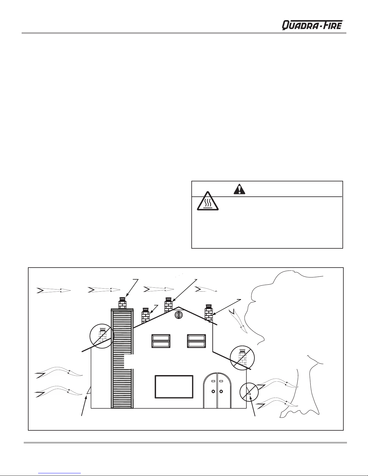
Location NOT recommended:
• Not the highest point of the roof
• Wind loading possible
Windward
Recommended:
Outside Air Intake
on windward side
Figure 6.1
Recommended Location:
• Above peak
Marginal Location:
• Below peak
Recommended:
• Insulated exterior chase
in cooler climates
Recommended Location:
• Above peak
• Inside heated space
Multi-level Roofs
Marginal Location:
• Wind loading possible
Location NOT recommended:
• Too close to tree
• Below adjacent structure
• Lower roof line
• Avoid outside wall
Leeward
NOT recommended:
Outside Air Intake
on leeward side
Page 6
7004-187I
December 20, 2011
R
Yosemite Wood Stove
D. Flue Draft Considerations
Location of the appliance and chimney will affect performance. As shown in Figure 6.1 on page 6 the chimney
should:
• Be installed through the warm space enclosed by the
building envelope. This helps to produce more draft,
especially during lighting and die down of the re.
• Penetrate the highest part of the roof. This minimizes
the affects of wind turbulence and down drafts.
• Consider the appliance location in order to avoid
oor and ceiling attic joists and rafters.
Exterior conditions such as roof line, surrounding trees,
prevailing winds and nearby hills can influence stove
performance. Your local dealer is the expert in your geographic
area and can usually make suggestions or discover solutions
that will easily correct your ue problem.
T
o be sure that your appliance burns properly, the chimney
draft (static pressure) should be approximately -.04 inch water
column (W.C.) during a low burn and -.10 inch W.C. during a
high burn, measured 6 inches (152mm) above the top of the
appliance after one hour of operation at each burn setting.
NOTE: These are guidelines only, and may vary somewhat
for individual installations.
E. Venting Systems
The venting system consists of a chimney connector (also
known as stove pipe) and a chimney. These get extremely
hot during use. Temperatures inside the chimney may
exceed 2000°F (1100°C) in the event of a creosote re. To
protect against the possibility of a house re, the chimney
connector and chimney must be properly installed and
maintained. An approved thimble must be used when a
connection is made through a combustible wall to a chimney.
A chimney support package must be used when a connection
is made through the ceiling to a prefabricated chimney.
These accessories are absolutely necessary to provide
safe clearances to combustible wall and ceiling material.
Follow venting manufacturer’s clearances when installing
venting system.
F. Tools And Supplies Needed
Before beginning the installation be sure that the following
tools and building supplies are available.
Reciprocating saw
Pliers
Hammer
Phillips Head Screwdriver
Flat Blade Screwdriver
Plumb Line
Level
Tape Measure
Framing Material
Non-Combustible Sealant
Gloves
Framing Square
Electric Drill & Bits (1/4”)
Safety Glasses
1/2 in. - 3/4 in. length, #6 or
#8 self drilling screws (need 3
per pipe section connection)
G. Inspect Appliance & Components and
Pre-Burn Check List
1. Place the appliance in a location near the nal
installation area and follow the procedures below:
2. Open the appliance and remove all the parts and
articles packed inside the Component Pack. Inspect
all the parts and glass for shipping damage. Contact
your dealer if any irregularities are noticed.
3. All safety warnings have been read and followed.
4. This Owner’s Manual has been read.
5. Floor protection requirements have been met.
6. Venting is properly installed.
7. The proper clearances from the appliance and
chimney to combustible materials have been met.
8. The masonry chimney is inspected by a professional
and is clean, or the factory built metal chimney is
installed according to the manufacturer’s instructions and clearances.
9. The chimney meets the required minimum height.
10.
11. A power outlet is available nearby if installing
All labels have been removed from the glass door.
optional blower assembly.
WARNING
Asphyxiation Risk.
• DO NOT CONNECT THIS UNIT TO A CHIM-
NEY FLUE SERVICING ANOTHER APPLIANCE.
• DO NOT CONNECT TO ANY AIR DISTRIBUTION DUCT OR SYSTEM.
May allow ue gases to enter the house.
WARNING
Fire Risk.
Inspect appliance and components for damage.
Damaged parts may impair safe operation.
• Do NOT install damaged components.
• Do NOT install incomplete components.
• Do NOT install substitute components.
Report damaged parts to dealer.
7004-187I December 20, 2011
Page 7
Yosemite Wood Stove
R
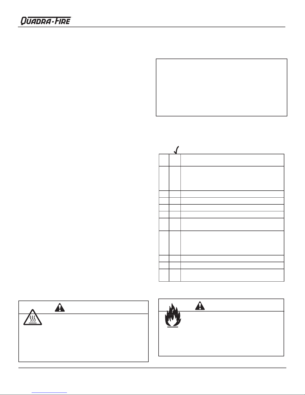
H. Typical Stove Systems
Stove system with masonry chimney
consists of: Figure 8.1
• Stove
• Chimney Connector (stove pipe)
• Thimble
• Masonry Chimney
• Hearth Pad Floor Protection
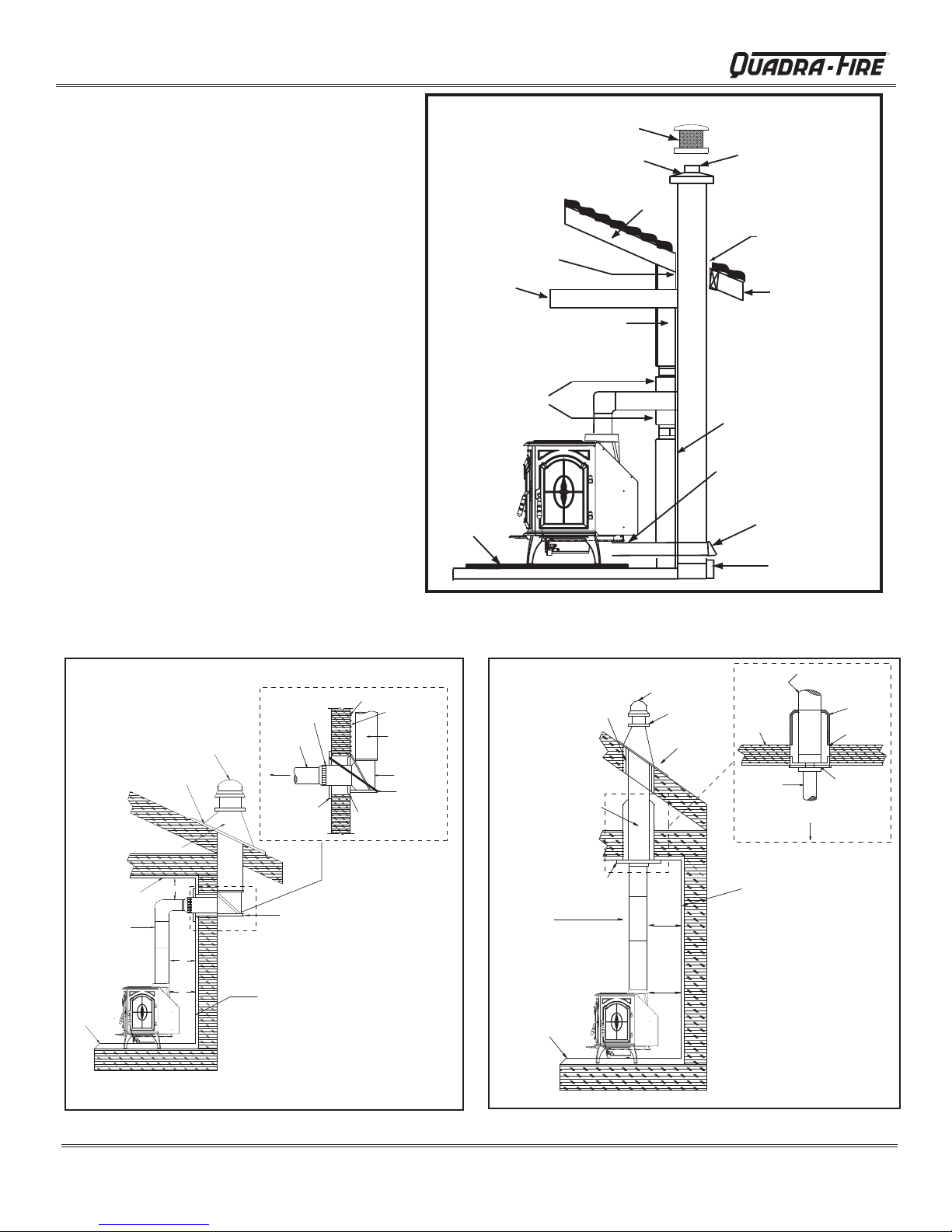
Stove system with prefabricated metal
chimney consists of: Figures 8.2 and 8.3
• Stove
•
Chimney Connector
(stove pipe)
• Thimble (for exterior
chimney)
• Firestops
• Insulations Shields
• Storm Collar and Flashing
• Termination Cap
• Hearth Pad Floor Protec-
tion
Spark Arrestor Cap
Concrete Cap
Rafter
1 in (25mm) Clearance
With Firestop
Ceiling Joist
Combustible Wall
Thimble,
12 in (305mm)
Of Brick
Floor
Protector
Figure 8.1 Masonry Chimney
Fireclay Flue Liner
With Air Space
Flashing
Eave
Sheathing
Outside Air Rear Vent
Outside Air
Termination Cap
Airtight
Cleanout Door
Listed
Chimney Pipe
Chimney
Connector
To Stove
Trim Collar
on Inside
Wall
Insulated "T"
Maintain 2" (51mm)
Clearance Through Eave
Flashing
Combustible
Ceiling
Chimney
Connector
Listed Cap
*
*
*
Floor
Protector
Figure 8.2 Exterior Prefabricated Chimney
Combustible Wall
*Refer to Clearances to Combustibles
Combustible Outside Wall
2" (51mm)
Clearance
Listed Chimney
Insulated "T"
Wall Support
Wall Spacer on
Outside Wall
Maintain 2" (51mm)
Clearance
Listed Chimney
Ceiling Support
Chimney
Connector
Floor
Protector
Listed Cap
Storm Collar
Flashing
*
*
Combustible
Ceiling
Joists
Chimney
Connector
Combustible Wall
*Refer to Clearances
to Combustibles
Figure 8.3 Interior Prefabricated Chimney
Listed
Chimney
To Stove
Attic
Insulation
Shield
Specified
Clearance
Ceiling
Support
Page 8
7004-187I
December 20, 2011

24-5/16"
14.0"
3
R
Yosemite Wood Stove
Dimensions and Clearances
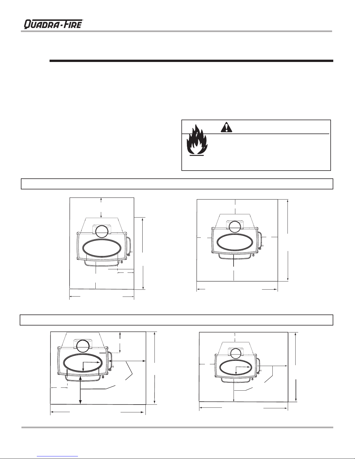
A. Appliance Dimensions
Front View
25-5/8"
(651mm)
19-7/16"
(494mm)
16-3/4"
(426mm)
25-5/16"
(643mm)
8-1/4"
(210mm)
13.0"
(230mm)
NOTE: Flue Collar size is 6 inch
(152mm) diameter (ID)
Top View Rear Vent
16-5/16"
(414mm)
Top View
C
L
14-15/16"
(379mm)
22-7/16"
(570mm)
19-5/16"
(491mm)
C
L
8-5/16"
(211mm)
Side View
20-7/16"
(519mm)
5-1/2"
(140mm)
(618mm)
Side View With Fuel Door
(356mm)
14-15/16"
(379mm)
14.0"
(356mm)
25.0"
(635mm)
C
L
25-1/2"
(648mm)
7004-187I December 20, 2011
Page 9

Yosemite Wood Stove
B. Clearances To Combustibles (UL And ULC)
R
B
C1
D1
Non-fuel
door side
A
Alcove
C2
D2
Fuel Door
side
Non-fuel
door side
E1
Vertical
F1
F2
E2
Fuel door
side
IF SIDE FUEL LOADING DOOR IS NOT USED:
• It must remain in the locked position at all times
• Use clearances for non-fuel door side for both sides
MINIMUM CLEARANCES TO COMBUSTIBLE MATERIALS: In Inches & (Millimeters)
NOTE: All "A" , "C" and "F" Dimensions are to the inside diameter of the flue collar.
TOP VENT VERTICAL A B C1 C2 D1 D2 E1 E2 F1 F2 G H
Single Wall-USA 12.5(316) 9(229) 19.5(495) 25.5(648) 10(254) 16 (406) 14(356) 16(406) 18.5(470) 20.5(521) 59(1499) N/A
Single Wall-Canada 12.5(316) 9(229) 19.5(495) 27.5(699) 10(254) 18 (457) 14(356) 18(457) 18.5(470) 22.5(572) 59(1499) N/A
Double Wall-USA 10.5(267) 7(178) 19.5(495) 25.5(648) 10(254) 16(406) 7 (178) 16(406) 11.5(292) 20.5(521) 59(1499) N/A
Double Wall-Canada 10.5(267) 7(178) 19.5(495) 27.5(699) 10(254) 18(457) 7 (178) 18(457) 11.5(292) 22.5(572) 59(1499) N/A
HORIZONTAL WITH MINIMUM 2FT (609mm) VERTICAL OFF STOVE TOP
Single Wall-USA 13.5(343) 10(254) 19.5(495) 25.5(648) 10(254) 16 (406) N/A N/A N/A N/A 59(1499) 18*
Single Wall-Canada 13.5(343) 10(254) 19.5(495) 27.5(699) 10(254) 18 (457) N/A N/A N/A N/A 59(1499) 18*
Double Wall-USA 11.5(330) 8(203) 19.5(495) 25.5(648) 10(254) 16(406) N/A N/A N/A N/A 59(1499) 18*
Double Wall-Canada 11.5(330) 8(203) 19.5(495) 27.5(699) 10(254) 18(457) N/A N/A N/A N/A 59(1499) 18*
90O ELBOW OFF TOP OF STOVE THROUGH BACKWALL
Single Wall-USA 13.5(343) 10(254) 19.5(495) 25.5(648) 10(254) 16 (406) N/A N/A N/A N/A 59(1499) N/A
Single Wall-Canada 13.5(343) 10(254) 19.5(495) 27.5(699) 10(254) 18 (457) N/A N/A N/A N/A 59(1499) N/A
Double Wall-USA 11(279) 7.5(191) 19.5(495) 25.5(648) 10(254) 16(406) N/A N/A N/A N/A 59(1499) N/A
Double Wall-Canada 11(279) 7.5(191) 19.5(495) 27.5(699) 10(254) 18(457) N/A N/A N/A N/A 59(1499) N/A
ALCOVE -
chimney, or a masonry chimney. (Mobile Home must be equipped with a spark arrestor.)
Six inch (6") (152mm) diameter listed DOUBLE WALL air insulated connector pipe with UL103 HT listed factory-built Class "A"
Max Depth Min Width Min Height
Front Door 48(1219) 44(1118) 54(1372)
Side Door-USA 48(1219) 56(1422) 54(1372)
Side Door-Canada 48(1219) 60(1524) 54(1372)
Max Mantel Depth
10" (254mm)
Ceiling
G
Horizontal
G*
Mantel
H
G
Ceiling
Vertical then Horizontal
Double Wall-USA 11.5(292) 8(203) 19.5(495) 25.5(648) 10(254) 16(406) N/A N/A N/A N/A 42(1067) N/A
Double Wall-Canada 11.5(292) 8(203) 19.5(495) 27.5(699) 10(254) 18(457) N/A N/A N/A N/A 42(1067) N/A
REAR VENT INSTALLATIONS
IN A MASONRY FIREPLACE OR THROUGH THE WALL:
listed double wall air insulated connector pipe with UL103 HT listed factory-built Class "A" chimney, or a masonry chimney. (Mobile Home
must be equipped with a spark arrestor). Additional specifications include a MAXIMUM 10" (254mm) MANTEL WIDTH and the following
clearances. Accessory Horizontal Heat Shield, Part HTSHLD-7006, is required for rear vent installations.
Double Wall-USA N/A 4(102) 19.5(495) 25.5(658) 10(254) 16(406) N/A N/A N/A N/A 30(762) ceiling N/A
Double Wall-Canada
N/A 4(102) 19.5(495) 27.5(699) 10(254) 18(457) N/A N/A N/A N/A 30(762) ceiling N/A
USA or Canada - Single or Double Wall Pipe: 21(533) mantel
*NFPA MINIMUM CLEARANCE - NOT TESTED
Page 10
7004-187I
Six inch (6") (152mm) diameter
December 20, 2011
R
Installation Considerations
4
A. Hearth Protection Requirements
FLOOR PROTECTION: Floor protector must be non-
combustible material, extending beneath heater and to the
front, sides and rear as indicated. The oor must be non-
combustible or otherwise adequately protected from radiant
heat given off by the unit and from sparks and falling embers.
A layer of thin brick or ceramic tile over a combustible oor
is not sufcient.
In US installations, i
tor a minimum of 16
inches (203mm) to both sides of the fuel loading door. Open
the door and measure 8 inches (203mm) from the side edge
of the opening in the face of the appliance. *See exception.
t is necessary to install a oor protec-
inches (406mm) in front of glass and 8
SIDE FUEL DOOR LOCKED SHUT
Yosemite Wood Stove
In Canada, similar oor protection must be provided 18
inches (457mm) in front and 8 inches (203mm) from the
sides and rear of the stove. *See exception.
*EXCEPTION: Non-combustible oor protections must
extend beneath the ue pipe when installed with horizontal
venting and extend 2 inches (51mm) beyond each side.
See Figure 11.4.
WARNING
Fire Risk.
• Hearth pads must be installed exactly as
specified.
High temperatures or hot embers may ignite
concealed combustibles.
16" (406mm) from fuel
Figure 11.1
Fuel loading doors
Front
8"
(200mm)
44-1/2"(1130mm) Minimum
Figure 11.3
10-1/2"
(267mm)
Front Fuel
loading door
loading door
33"(838mm) Minimum
8"(200mm)
Side
200mm
(8")
36-3/4"
(933mm)
Minimum
8"
(200mm)
USA
1010mm (39-3/4")
Figure 11.2
BOTH FUEL DOORS ACCESSIBLE
200mm
(8")
Figure 11.4
Minimum 16"
(406mm) from
fuel loading
door
USA
36-3/4"
(932mm)
Minimum
200mm (8")
450mm (18")
Minimum
200mm (8")
Fuel loading doors
1264mm (49-3/4") Minimum
Front
Side
Minimum 450mm
(18") from each
fuel loading door
200mm
(8")
CANADA
CANADA
1187mm
(46-3/4")
Minimum
1187mm
(46-3/4")
Minimum
7004-187I December 20, 2011
Page 11
Yosemite Wood Stove
16"
16"
36-3/4"
11-3/8"
17-1/4"
27-1/4"
41-3/8"
48-1/2"
optional coverage
optional
coverage
8"
required coverage
Fuel loading door
44-1/2"
optional
coverage
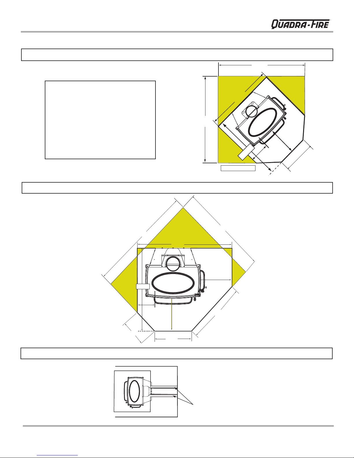
A. Hearth Protection Requirements (Cont'd)
SIDE FUEL DOOR LOCKED SHUT - CORNER
NOTE:
• Illustrations and photos reect typical
installations and are FOR DESIGN
PURPOSES ONLY.
• Illustrations/diagrams are not drawn to
scale.
• Actual installation may vary due to
individual design preference
• Hearth & Home Technologies reserves the
right to alter its products.
44-3/4"
Figure 12.1
33.0"
optional coverage
optional
coverage
USA Installations
36-3/4"
44-3/4"
Front fuel
loading door
8"
optional
coverage
16"
required coverage
26-3/4"
R
BOTH FUEL DOORS ACCESSIBLE- CORNER
Figure 12.2
HORIZONTAL VENTING
Page 12
Figure 12.3
7004-187I
Floor protection must extend
length of flue and 2 inches
(51mm) beyond each side of
pipe (shaded area).
December 20, 2011
R
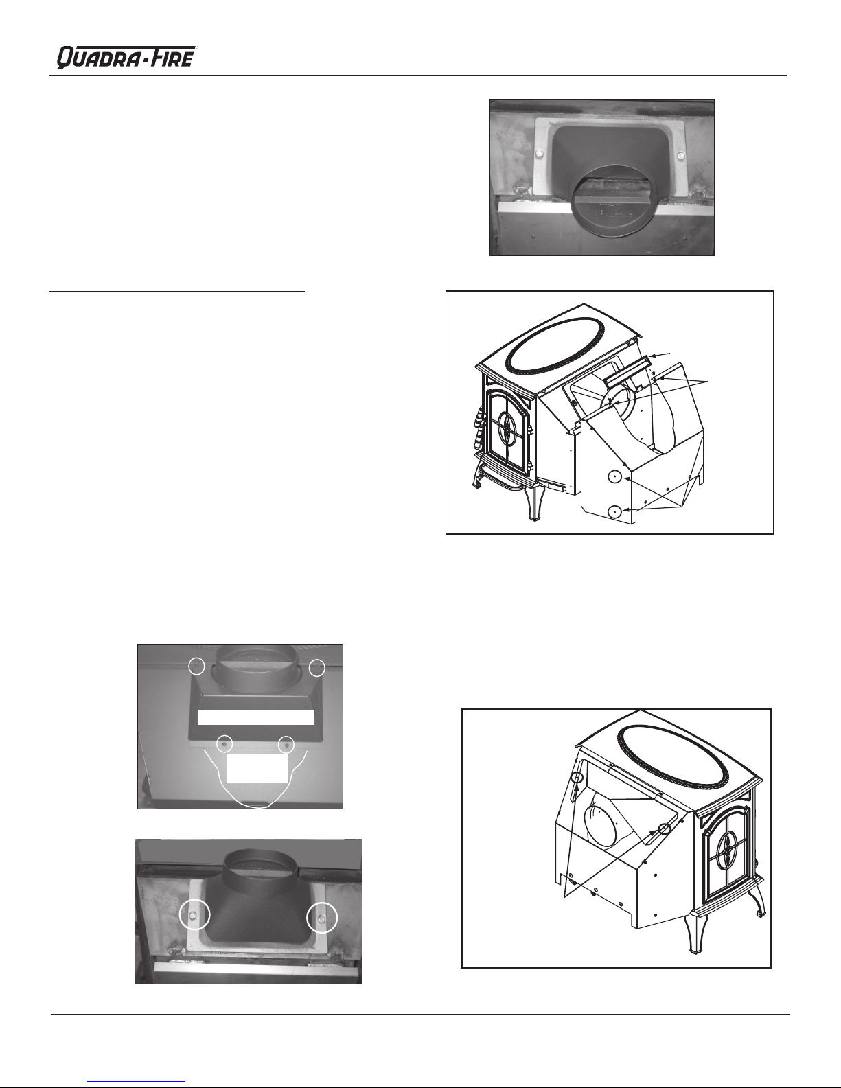
B. Reversible Flue Collar
Tools Required: Phillips head screwdriver; 3/8" and 7/16"
wrench
The ue collar is reversible for either a top or rear venting
installation. Accessory Horizontal Flue Heat Shield, Part
HTSHLD-7006, is required in rear vent installations. The
appliance is shipped with the ue collar in the top vent position.
Converting Collar For Rear Vent Installation
1. Lift off cast top. Remove 4 Phillips head screws from the
heat shield. Discard heat shield and save the screws.
Figure 13.1.
2. Remove 4 Phillips head screws from the rear shield, 2 on
each side, lift shield off and set aside. Figure 13.4.
3.
Remove 1 bolt from each side of the flue transition.
and retrieve nuts attached to bolts. Use 3/8" and 7/16"
wrenches.
4. Turn vent to horizontal position. Inspect sealant to ensure
a leak free application. Figure 13.3.
5 Manually snap off the knock-out section and discard. See
white outline in Figure 13.1.
6. Re-attach the rear shield on both sides.
7. Position the bracket (found in the component pack inside
the rebox) over the opening on the rear shield. Use 2
screws removed in Step #1 to secure the bracket. Figure
13.4.
8. Place cast top on the unit.
Figure 13.2.
Yosemite Wood Stove
Figure 13.3
Bracket
Attach
bracket
to rear
shield
2 screws on
each side
Figure 13.4
C. Horizontal Flue Heat Shield
Required Accessory Part: HTSHLD-7006
Figure 13.1
Figure 13.2
Discard Heat Shield
Knock Out
Section
Place horizontal ue heat shield over rear shield as shown in
Figure 13.5. Secure with the remaining 2 screws removed
in Step #1 under Reversing Flue Collar.
Secure
Horizontal Flue Heat
Shield
Figure 13.5
7004-187I December 20, 2011
Page 13
Yosemite Wood Stove
R
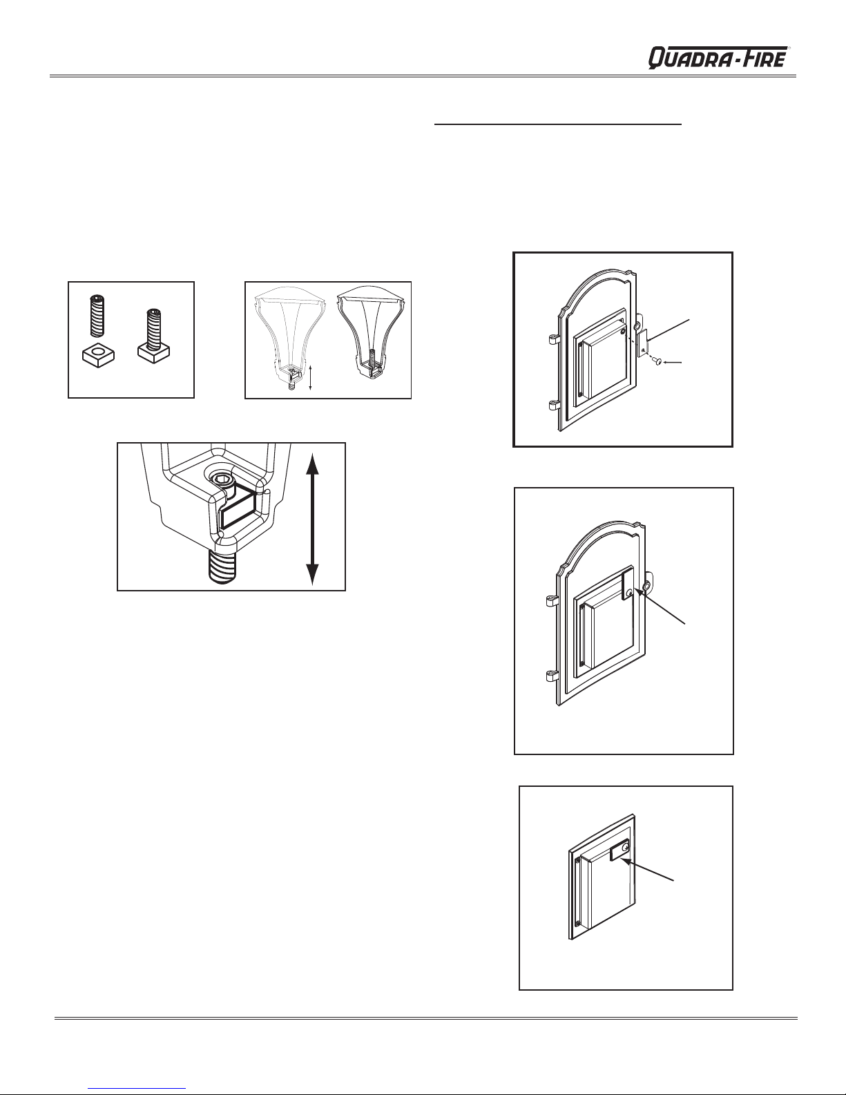
D. Leg Leveling System
1. Thread Allen bolts through nuts until ush. Figure 14.1.
The
Allen bolts and nuts are included in the component pack
inside the appliance rebox.
2. Slide assembled nuts and bolts into slots on legs with the
nuts on the bottom. Figure 14.2. Use a 5/32 Allen wrench
to adjust legs up and down to desired level. Figure 14.3.
Figure 14.1
Figure 14.2
Instructions To Unlock Side Fuel Door
1. Open front door.
2. Using a Phillips head screwdriver, remove the screw
from the locking bracket. Figure 14.4.
3. Rotate locking bracket to horizontal position and secure
in place using the same screw.
Door Locking
Bracket
Screw
Figure 14.4
Locked Position
Figure 14.3 - Bolt fully extended
E. Side Fuel-Loading-Door Locking
Mechanism
The side fuel loading door is shipped locked in place. Figure
14.5
You must rst decide where you are locating your stove and
determine if you meet the minimum required clearances
from combustibles for loading wood into the rebox from
the side door.
If you do not meet the clearances found on page 10, leave the
door locked in place. If you unlock the door without meeting
the minimum required clearances YOU WILL VOID YOUR
WARRANTY AND ASSUME ALL RESPONSIBILITIES.
If you meet the minimum clearances, follow the instructions
to unlock the door.
If in the future you decide to relocate your stove, again
determine if you meet the mimimum required clearances
to combustibles in the new location. If you do not, you are
required to lock the door shut and it must remain locked at
all times.
Bracket
Bracket in Vertical
Position
Figure 14.5
Unlocked Position
Bracket
Bracket in Horizontal
Position
Figure 14.6
Page 14
7004-187I
December 20, 2011
 Loading...