


QV36B-A
1Quadra-fire • QV32B-A, QV36B-A • 2014-900 Rev. F • 9/06
- Do not store or use gasoline or other flam-
mable vapors and liquids in the vicinity of this
or any other appliance.
- What to do if you smell gas
• Do not try to light any appliance.
• Do not touch any electrical switch.
• Do not use any phone in your building.
• Immediately call your gas supplier from a
neighbor's phone. Follow the gas supplier's
instructions.
• If you cannot reach your gas supplier, call
the fire department.
- Installation and service must be performed by a
qualified installer, service agency, or the gas
supplier.
Models:
QV32B-A
QV36B-A
Installers Guide
WARNING: IMPROPER INSTALLA-
TION, ADJUSTMENT, ALTERATION,
SERVICE OR MAINTENANCE CAN
CAUSE INJURY OR PROPERTY DAM-
AGE. REFER TO THIS MANUAL. FOR
ASSIST ANCE OR ADDITIONAL INFOR-
MATION CONSULT A QUALIFIED IN-
ST ALLER, SERVICE AGENCY , OR THE
GAS SUPPLIER.
Underwriters
Laboratories Listed
READ THIS MANUAL BEFORE INSTALLING OR
OPERA TING THIS APPLIANCE. THIS INSTALLERS
GUIDE MUST BE LEFT WITH APPLIANCE FOR
FUTURE REFERENCE.
1.This appliance may be installed in an af-
termarket, permanently located, manufac-
tured (mobile) home, where not prohibited
by local codes.
2. This appliance is only for use with the type
of gas indicated on the rating plate. This
appliance is not convertible for use with
other gases, unless a certified kit is used.
Please contact your Quadra-Fire dealer
with any questions or concerns. For the
number of your nearest Quadra-Fire
dealer, please visit www .quadrafire.com.
Printed in U.S.A. Copyright 2006
WARNING: IF THE INFORMATION
IN THESE INSTRUCTIONS IS NOT
FOLLOWED EXACTL Y, A FIRE OR
EXPLOSION MAY RESULT CAUS-
ING PROPERTY DAMAGE, PER-
SONAL INJURY, OR DEA TH.
Quadra-Fire, a brand of Hearth & Home Technologies
1445 North Highway, Colville, WA 99114
This product may be covered by one or more of the following patents: (United States) 4593510, 4686807, 4766876, 4793322, 481 1534, 5000162, 5016609, 5076254, 51 13843, 5191877, 5218953, 5263471,
5328356, 5341794, 5347983, 5429495, 5452708, 5542407, 5601073, 5613487, 5647340, 5688568, 5762062, 5775408, 5890485, 5931661, 5941237, 5947112, 5996575, 6006743, 6019099, 6048195, 6053165,
6145502, 6170481, 6237588, 6296474, 6374822, 6413079, 6439226, 6484712, 6543698, 6550687, 6601579, 6672860, 6688302B2, 6715724B2, 6729551, 6736133, 6748940, 6748942, 6769426, 6774802,
6796302, 6840261, 6848441, 6863064, 6866205, 6869278, 6875012, 6880275, 6908039, 6919884, D320652, D445174, D462436; (Canada) 1297749, 2195264, 2225408, 2313972; (Australia) 780250,
780403, 1418504 or other U.S. and foreign patents pending.
In the Commonwealth of Massachusetts:
• installation must be performed by a licensed
plumber or gas fitter;
See T able of Content s for location of additional
Commonwealth of Massachusetts requirements.
2 Quadra-fire • QV32B-A, QV36B-A • 2014-900 Rev. F • 9/06
These units MUST use one of the vent systems
described in the Installing the Fireplace section of
the Installers Guide. NO OTHER vent systems or
components MAY BE USED.
This gas fireplace and vent assembly MUST be
vented directly to the outside and MUST NEVER be
attached to a chimney serving a separate solid fuel
burning appliance. Each gas appliance MUST USE
a separate vent system. Common vent systems are
PROHIBITED.
INSPECT the external vent cap on a regular basis to
make sure that no debris is interfering with the air
flow.
The glass door assembly MUST be in place and
sealed, and the trim door assembly MUST be in
place on the fireplace before the unit can be placed
into safe operation.
DO NOT OPERATE this appliance with the glass
door removed, cracked, or broken. Replacement of
the glass door should be performed by a licensed
or qualified service person. DO NOT strike or slam
the glass door.
The glass door assembly SHALL ONLY be
replaced as a complete unit, as supplied by the gas
fireplace manufacturer. NO SUBSTITUTE material
may be used.
DO NOT USE abrasive cleaners on the glass door
assembly. DO NOT ATTEMPT to clean the glass
door when it is hot.
Turn off the gas before servicing this appliance. It is
recommended that a qualified service technician
perform an appliance check-up at the beginning of
each heating season.
Any safety screen or guard removed for servicing
must be replaced before operating this appliance.
DO NOT place furniture or any other combustible
household objects within 36 inches of the fireplace
front.
READ and UNDERSTAND all instructions carefully
before starting the installation. FAILURE TO
FOLLOW these installation instructions may result
in a possible fire hazard and will void the warranty.
Prior to the first firing of the fireplace, READ the
Using Your Fireplace section of the Owners Guide.
DO NOT USE this appliance if any part has been
under water. Immediately CALL a qualified service
technician to inspect the unit and to replace any part
of the control system and any gas control which has
been under water.
THIS UNIT IS NOT FOR USE WITH SOLID FUEL.
Installation and repair should be PERFORMED by a
qualified service person. The appliance and venting
system should be INSPECTED before initial use
and at least annually by a professional service
person. More frequent cleaning may be required
due to excessive lint from carpeting, bedding
material, etc. It is IMPERATIVE that the unit’s
control compartment, burners, and circulating air
passageways
BE KEPT CLEAN to provide for
adequate combustion and ventilation air.
Always KEEP the appliance clear and free from
combustible materials, gasoline, and other
flammable vapors and liquids.
NEVER OBSTRUCT the flow of combustion and
ventilation air. Keep the front of the appliance
CLEAR of all obstacles and materials for servicing
and proper operations.
Due to the high temperature, the appliance should
be LOCATED out of traffic areas and away from
furniture and draperies. Clothing or flammable
material SHOULD NOT BE PLACED on or near the
appliance.
Children and adults should be ALERTED to the
hazards of high surface temperature and should
ST AY A WA Y to avoid burns or clothing ignition.
Y oung children should be CAREFULL Y SUPERVISED
when they are in the same room as the appliance.
!
!
!
!
!
!
!
!
!
!
!
!
!
!
!
!
!
SAFETY AND WARNING INFORMATION
!
!

3Quadra-fire • QV32B-A, QV36B-A • 2014-900 Rev. F • 9/06
TABLE OF CONTENTS
Safety and Warning Information ......................................................... 2
Service Parts Lists.................................................................................4
Section 1: Approvals and Codes.......................................................... 9
Appliance Certification ............................................................................. 9
Installation Codes .................................................................................... 9
High Altitude Installations ........................................................................ 9
Requirements for the Commonwealth of Massachusetts........................ 10
Section 2: Getting Started .................................................................. 11
Introducing the Village Collection Gas Fireplaces .................................. 1 1
Pre-installation Preparation.................................................................... 11
Section 3: Installing the Fireplace..................................................... 14
Constructing the Fireplace Chase .......................................................... 14
Step 1 Locating the Fireplace........................................................... 14
Step 2 Framing the Fireplace ........................................................... 15
Step 3 Installing the Vent System .................................................... 18
A. Vent System Approvals ................................................... 18
B. Installing V ent Components............................................. 28
C. Vent Termination .............................................................. 31
Step 4 Positioning, Leveling, and
Securing the Fireplace .......................................................... 34
Step 5 The Gas Control Systems..................................................... 34
Step 6 The Gas Supply Line............................................................. 35
Step 7 Gas Pressure Requirements................................................. 35
Step 8 Wiring the Fireplace .............................................................. 36
Step 9 Finishing ............................................................................... 37
Step 10 Installing Trim, Logs, and Ember Material ............................. 3 7
Shutter Settings.................................................................... 37
Placing the Ember Material................................................... 38
Step 1 1 Before Lighting the Fireplace................................................. 38
Step 12 Lighting the Appliance ........................................................... 39
After the Installation ............................................................................... 39
Section 4: Maintaining and Servicing Your Fireplace .................... 40
Section 5: Troubleshooting ............................................................... 41
Limited Lifetime Warranty ...................................................................... 43
Î = Contains updated information.
Î
Í
4 Quadra-fire • QV32B-A, QV36B-A • 2014-900 Rev. F • 9/06
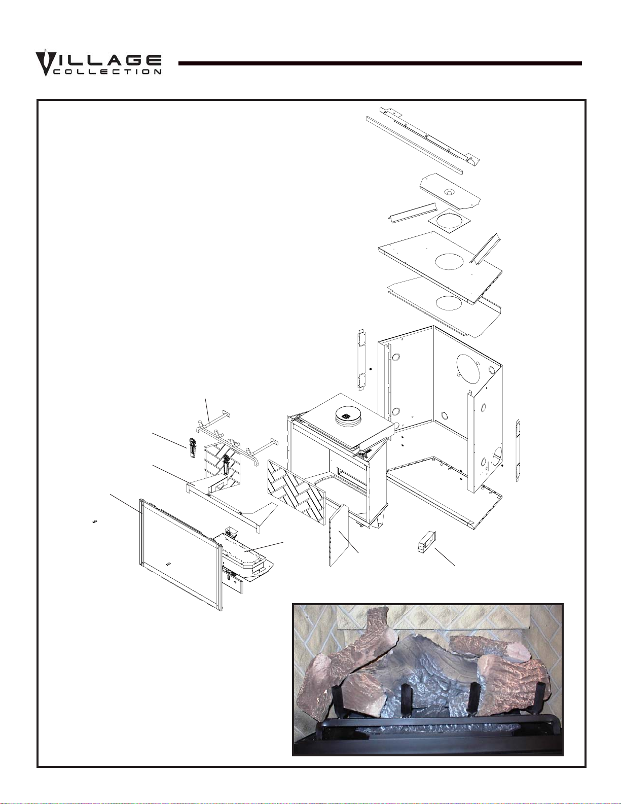
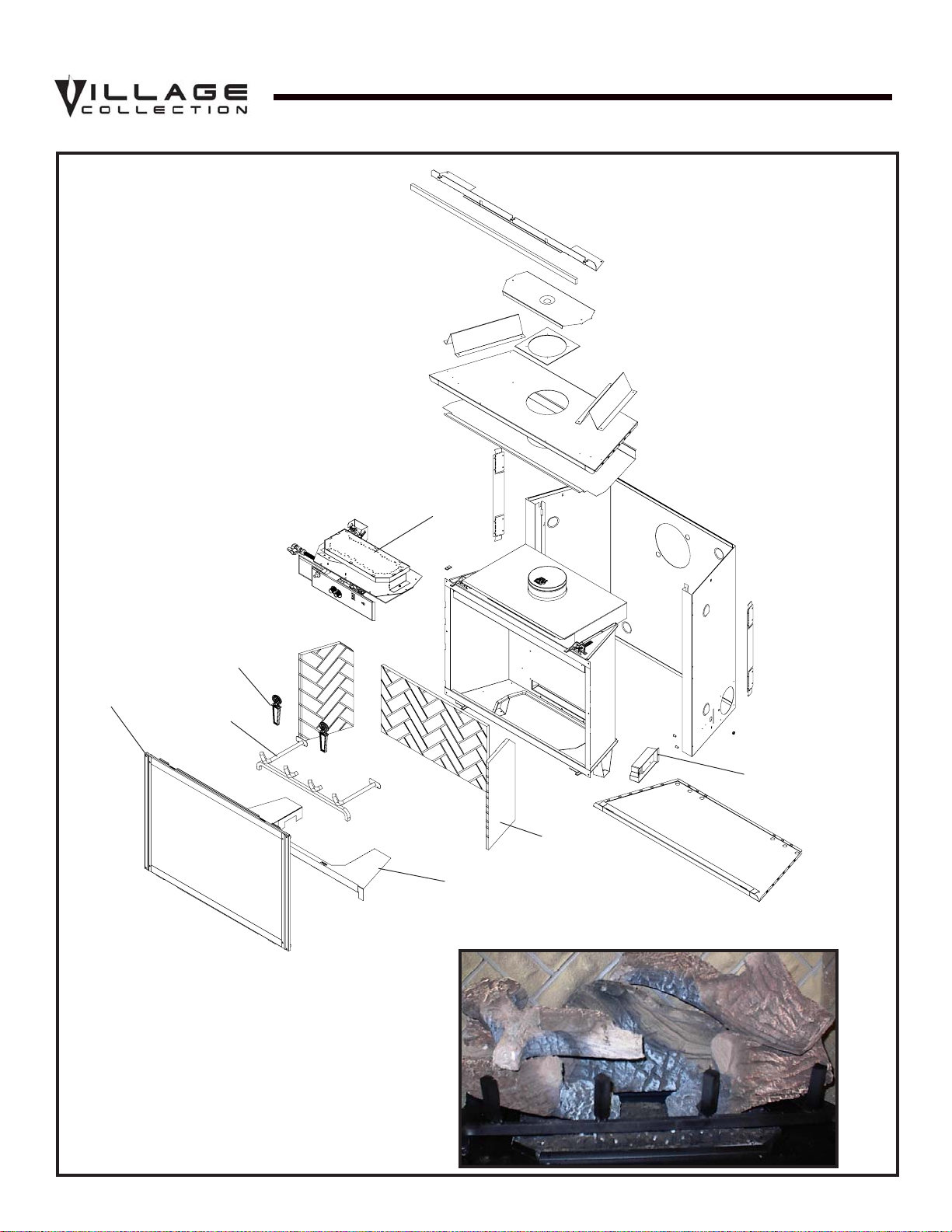
Part number list on following page.
4
3
5
2
7
1
6
(NG , LP) Exploded Parts Diagram
Service Parts
QV32B-A
Beginning Manufacturing Date: 6-03
Ending Manufacturing Date: ______
8 Log Set Assembly
12
11
10
9
13
Î
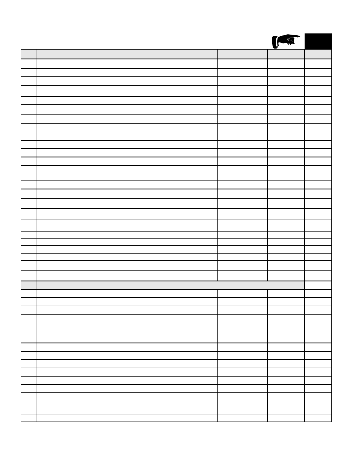
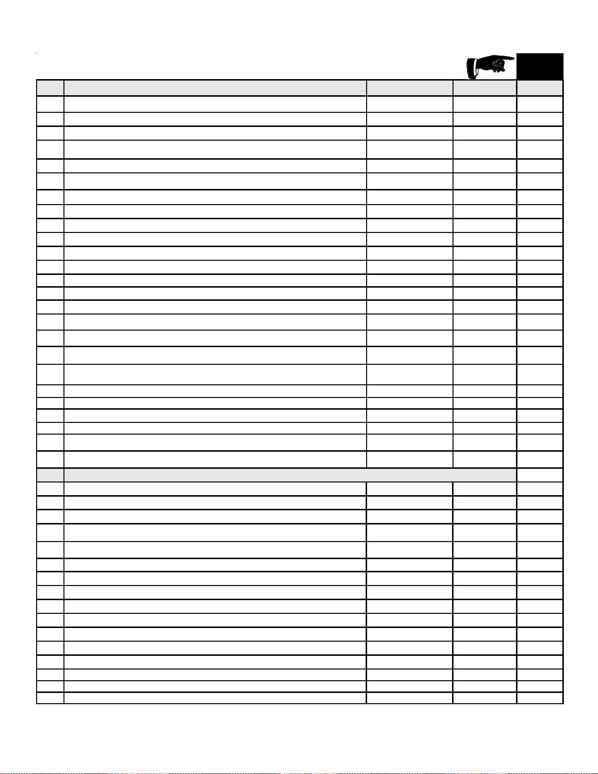
5Quadra-fire • QV32B-A, QV36B-A • 2014-900 Rev. F • 9/06
AVAILABLE
TO SHIP IN
24 HOURS
ITEM STANDING PILOT IGNITION SERIAL # PART NUMBER
Burner Orifice NG (#38C) 582-838 Y
Burner Orifice LP (1.55mmC) 582-8155 Y
1 Andirons, Cast 80784
2 Burner
Pre 10-06
Post 10-06
2014-004
2014-014
Y
3 Glass Door Assembly GLA-550TRS Y
4 Log Grate 2014-001
5 Base Pan NG, LP 2014-100
6 Refractory Kit (Sold as set only) BRICK-293-2
7 J unc tio n Box 100-250A Y
8 Log Set Assembly LOGS-2014 Y
9Log 1 SRV2014-701
10 Log 2 SRV2014-703
11 Log 3 SRV2014-702
12 Log 4 SRV780-707
13 Log 5 SRV2014-704
Pilot Orifice NG
Pre 10-06
Post 10-06
446-505
2103-116
Y
Pilot Orifice LP
Pre 10-06
Post 10-06
446-517
2103-117
Y
Thermocouple
Pre 10-06
Post 10-06
446-511
2103-511
Y
Thermopile
Pre 10-06
Post 10-06
060-512
2103-512
Y
Lava Rock 060-721
Mineral Wool 050-721
Exhaus t R es t ric t or 530-299
Glass Latch Assembly 386-122A Y
Regulator NG
Pre 10-06
Post 10-06
060-518
230-1570
Y
Y
Regulator LP
Pre 10-06
Post 10-06
060-519
230-1520
Y
Y
ACCESSORIES
Fan Kit GFK-160A
Wall Switch Kit, Off-white WSK-21-HTI
Wall Switch Kit, White WSK-21-W-HTI
Conversion Kit NG
Pre 10-06
Post 10-06
NGK-2014
NGKS-2014
Y
Conversion Kit LP
Pre 10-06
Post 10-06
LPK-2014
LPKS-2014
Y
Door Front - Remington Ave. DF-32RA-BK
Door Front - Remington Ave. DF-32RA-HP
Door Front - Sun Prairie Operable DF-32SPO-BK
Door Front - Sun Prairie Operable DF-32SPO-HP
Door Front - Sun Prairie Operable DF-32SPO-VC
Do o r Fro nt - Town S quare DF-32TS-BK
Do o r Fro nt - Town S quare DF-32TS-HP
Door Front - Harmony Hall DF-32HH-B K
Hood, Black SRV550-175
Hood, Hammered Pewter SRV550-175-HP
Hood, Hammered Pewter SRV550-175-HP
(NG , LP) Service Part s List
IMPORTANT: THIS IS DA TED INFORMA TION. The most current information is located on your
dealers VIP site. When ordering, supply serial and model numbers to ensure correct service parts.
QV32B-A
Î
Í
6 Quadra-fire • QV32B-A, QV36B-A • 2014-900 Rev. F • 9/06
9
11
12
13
1
2
3
4
5
7
6
8 Log Set Assembly
10
(NG , LP) Exploded Parts Diagram
Service Parts
QV36B-A
Beginning Manufacturing Date: 6-03
Ending Manufacturing Date: ______
Î
7Quadra-fire • QV32B-A, QV36B-A • 2014-900 Rev. F • 9/06
(NG, LP) Service Parts List
IMPORTANT: THIS IS DATED INFORMATION. The most current information is located on your
dealers VIP site. When ordering, supply serial and model numbers to ensure correct service parts.
QV36B-A
AVAILABLE
TO SHIP IN
24 HOURS
ITEM STANDING PILOT IGNITION SERIAL # PART NUMBER
Burner Orifice NG (#38C) 582-838 Y
Burner Orifice LP (1.55mmC) 582-8155 Y
1 Andirons, C ast 80784
2Burner
Pre 10-06
Post 10-06
2014-004
2014-014
Y
3 G las s Do or As se mb ly GLA-550TRS Y
4 Log Grate 2014-001
5 Base Pan NG, LP 2014-100
6 Refractory Kit (Sold as set only) BRICK-293-2
7 J unc ti on B ox 100-250A Y
8 Log Set Assembly LOGS-2014 Y
9 Log 1 SRV2014-701
10 Log 2 SRV2014-703
11 Log 3 SRV2014-702
12 Log 4 SRV780-707
13 Log 5 SRV2014-704
Pilot Orifice NG
Pre 10-06
Post 10-06
446-505
2103-116
Y
Pilot Orifice LP
Pre 10-06
Post 10-06
446-517
2103-117
Y
Thermocouple
Pre 10-06
Post 10-06
446-511
2103-511
Y
Thermopile
Pre 10-06
Post 10-06
060-512
2103-512
Y
Lava Rock 060-721
Mineral Wool 050-721
Exhaus t R e s tr i c t o r 530-299
Glass Latch Assembly 386-122A Y
Regulator NG
Pre 10-06
Post 10-06
060-518
230-1570
Y
Y
Regulator LP
Pre 10-06
Post 10-06
060-519
230-1520
Y
Y
ACCESSORIES
Fan Kit GFK-160A
Wall Switch Kit, Off-white WSK-21-HTI
Wall Switch Kit, White WSK-21-W-HTI
Conversion Kit NG
Pre 10-06
Post 10-06
NGK-20 1 4
NGKS -2 0 1 4
Y
Conversion Kit LP
Pre 10-06
Post 10-06
LPK-2014
LPKS-2014
Y
Doo r F ront - Re m i ng to n Ave. DF-32RA-BK
Doo r F ront - Re m i ng to n Ave. DF-32RA-HP
Door Front - Sun Prairie Operable DF-32SPO-BK
Door Front - Sun Prairie Operable DF-32SPO-HP
Door Front - Sun Prairie Operable DF-32SPO-VC
Doo r F ro nt - Town Squa re DF-32TS-BK
Doo r F ro nt - Town Squa re DF-32TS-HP
Doo r F ro nt - Harm o ny Ha ll DF -3 2 HH-B K
Hood, Black SRV550-175
Hood, Hammered Pewter SRV550-175-HP
Hood, Hammered Pewter SRV550-175-HP
Î
Í
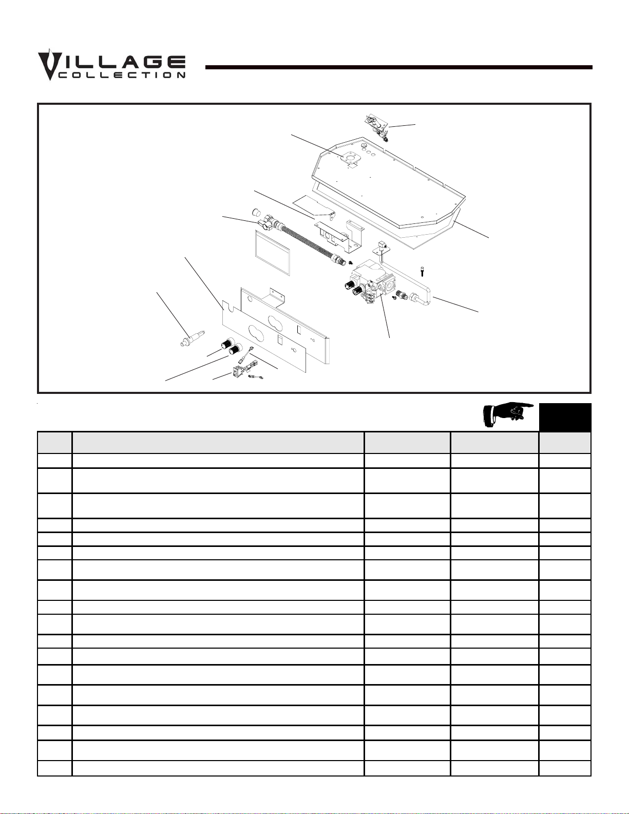
8 Quadra-fire • QV32B-A, QV36B-A • 2014-900 Rev. F • 9/06
(NG , LP) Exploded Parts Diagram
Service Parts
QV32B-A, QV36B-A
Beginning Manufacturing Date: 6-03
Ending Manufacturing Date: ______
AVAILAB LE
TO S HIP IN
24 HOURS
ITEM DESCRIPTION SERIAL # PART N UMBE R
1ON/OFF Rocker Switch 060-521A Y
2Valve NG
PRE 10-06
POST 10-06
060-522
230-0710
Y
2 Valve LP
PRE 10-06
POST 10-06
060-523
230-0720
Y
3 Flexible Gas Connector 530-302A Y
4 Valve Plate Gasket 530-431
5Burner Neck Gasket 2046-407
6Pilot Assembly NG
PRE 10-06
POST 10-06
530-510A
2103-010
Y
6 Pilot Assembly LP
PRE 10-06
POST 10-06
530-511A
2103-011
Y
7Wire Assembly 049-552a
8 Valve Bracket
PRE 10-06
POST 10-06
2025-101
2025-101, 2044-155
9 Fle x B all Valve As s embly 302-320A Y
10 Piezo Ignitor 291-513 Y
11 Pilot Control Knob
PRE 10-06
POST 10-06
291-530
571-531
12 Flame Control Knob
PRE 10-06
POST 10-06
291-531
571-534
13 Control Panel
PRE 10-06
POST 10-06
291-119
291-125
14 Shutter Bra c ket Assem b ly 2026-017 Y
Pilot Bracket
PRE 10-06
POST 10-06
2065-117
N/A
Shutter Sleeve 2026-130
Standing Pilot Ignition
Valve Assembly
13
4
2
9
10
8
5
6
3
1
Î
11
12
7

9Quadra-fire • QV32B-A, QV36B-A • 2014-900 Rev. F • 9/06
1
Approvals and
Codes
NOTE: THESE MODELS ARE UL LISTED TO UL307B,
THE ST ANDARD FOR GAS-BURNING HEATING APPLI-
ANCES FOR MANUFACTURED HOMES AND RECRE-
A TIONAL VEHICLES.
Installation Codes
The fireplace installation must conform to local codes. Before
installing the fireplace, consult the local building code
agency to ensure that you are in compliance with all
applicable codes, including permits and inspections.
In the absence of local codes, the fireplace installation must
conform to the National Fuel Gas Code ANSI Z223.1 (in
the United States) or the CAN/CGA-B149 Installation Codes
(in Canada). The appliance must be electrically grounded
in accordance with local codes or, in the absence of local
codes with the National Electric Code ANSI/NFPA No. 70
(in the United States), or to the CSA C22.1 Canadian Electric
Code (in Canada).
These models may be installed in a bedroom or bed-sitting
room in the U.S.A. and Canada.
Appliance Certification
The Village Collection fireplace models discussed in this
Installers Guide have been tested to certification standards
and listed by the applicable laboratories.
Certification
MODELS: QV32B-A, QV36B-A
LABORA TORY : Underwriters Laboratories
TYPE: Vented Gas Fireplace Heater
STANDARD: ANSI Z21.88•CSA2.33•UL307B
High Altitude Installations
U.L. Listed gas appliances are tested and approved without
requiring changes for elevations from 0 to 2,000 feet in the
U. S. A. and in Canada.
When installing this appliance at an elevation above 2,000
feet, it may be necessary to decrease the input rating by
changing the existing burner orifice to a smaller size. Input
rate should be reduced by 4% for each 1000 feet above a
2000 foot elevation in the U.S.A. or 10% for elevations
between 2000 and 4500 feet in Canada. If the heating value
of the gas has been reduced, these rules do not apply . To
identify the proper orifice size, check with the local gas
utility.
If installing this appliance at an elevation above 4,500 feet
(in Canada), check with local authorities.

10 Quadra-fire • QV32B-A, QV36B-A • 2014-900 Rev. F • 9/06
For all side wall horizontally vented gas fueled equipment
installed in every dwelling, building or structure used in
whole or in part for residential purposes, including those
owned or operated by the Commonwealth and where the
side wall exhaust vent termination is less than seven (7)
feet above finished grade in the area of the venting, includ-
ing but not limited to decks and porches, the following re-
quirements shall be satisfied:
Installation of Carbon Monoxide Detectors
At the time of installation of the side wall horizontal vented
gas fueled equipment, the installing plumber or gasfitter
shall observe that a hard wired carbon monoxide detector
with an alarm and battery back-up is installed on the floor
level where the gas equipment is to be installed. In addi-
tion, the installing plumber or gasfitter shall observe that a
battery operated or hard wired carbon monoxide detector
with an alarm is installed on each additional level of the
dwelling, building or structure served by the side wall hori-
zontal vented gas fueled equipment. It shall be the respon-
sibility of the property owner to secure the services of qual-
ified licensed professionals for the installation of hard wired
carbon monoxide detectors.
In the event that the side wall horizontally vented gas fu-
eled equipment is installed in a crawl space or an attic, the
hard wired carbon monoxide detector with alarm and bat-
tery back-up may be installed on the next adjacent floor
level.
In the event that the requirements of this subdivision can
not be met at the time of completion of installation, the
owner shall have a period of thirty (30) days to comply with
the above requirements; provided, however, that during said
thirty (30) day period, a battery operated carbon monoxide
detector with an alarm shall be installed.
Approved Carbon Monoxide Detectors
Each carbon monoxide detector as required in accordance
with the above provisions shall comply with NFP A 720 and
be ANSI/UL 2034 listed and IAS certified.
Signage
A metal or plastic identification plate shall be permanently
mounted to the exterior of the building at a minimum height
of eight (8) feet above grade directly in line with the ex-
haust vent terminal for the horizontally vented gas fueled
heating appliance or equipment. The sign shall read, in
print size no less than one-half (1/2) inch in size, “GAS
VENT DIRECTLY BELOW. KEEP CLEAR OF ALL OB-
STRUCTIONS”.
Inspection
The state or local gas inspector of the side wall horizontally
vented gas fueled equipment shall not approve the installa-
tion unless, upon inspection, the inspector observes carbon
monoxide detectors and signage installed in accordance with
the provisions of 248 CMR 5.08(2)(a)1 through 4.
Exemptions
The following equipment is exempt from 248 CMR 5.08(2)(a)1
through 4:
• The equipment listed in Chapter 10 entitled “Equipment
Not Required To Be Vented” in the most current edition
of NFP A 54 as adopted by the Board; and
• Product Approved side wall horizont ally vented gas fu-
eled equipment installed in a room or structure sepa-
rate from the dwelling, building or structure used in whole
or in part for residential purposes.
MANUFACTURER REQUIREMENTS
Gas Equipment Venting System Provided
When the manufacturer of Product Approved side wall hor-
izontally vented gas equipment provides a venting system
design or venting system components with the equipment,
the instructions provided by the manufacturer for installa-
tion of the equipment and the venting system shall include:
• Detailed instructions for the installation of the venting
system design or the venting system components; and
• A complete parts list for the venting system design or
venting system.
Gas Equipment Venting System NOT Provided
When the manufacturer of a Product Approved side wall
horizontally vented gas fueled equipment does not provide
the parts for venting the flue gases, but identifies “special
venting systems”, the following requirements shall be sat-
isfied by the manufacturer:
• The referenced “special venting system” instructions shall
be included with the appliance or equipment installation
instructions; and
• The “special venting systems” shall be Product Approved
by the Board, and the instructions for that system shall
include a parts list and detailed installation instructions.
A copy of all installation instructions for all Product Ap-
proved side wall horizontally vented gas fueled equipment,
all venting instructions, all parts lists for venting instruc-
tions, and/or all venting design instructions shall remain
with the appliance or equipment at the completion of the
installation.
See Gas Connection section for additional Common-
wealth of Massachusetts requirements.
NOTE: The following requirements reference various
Massachusetts and national codes not contained in
this document.
Requirements for the Commonwealth of
Massachusetts

11Quadra-fire • QV32B-A, QV36B-A • 2014-900 Rev. F • 9/06
2
Getting Started
Introducing the Village Collection
Gas Fireplaces
The Village Collection direct vent gas fireplaces are designed
to operate with all combustion air siphoned from outside of
the building and all exhaust gases expelled to the outside.
The information contained in this Installers Guide, unless
noted otherwise, applies to all models and gas control
systems. Gas fireplace diagrams, including the dimensions,
are shown in this section.
Pre-install Preparation
This gas fireplace and its components are tested and safe
when installed in accordance with this Installers Guide.
Report to your dealer any parts damaged in shipment,
particularly the condition of the glass. Do not install any
unit with damaged, incomplete, or substitute parts.
The vent system components and trim doors are shipped
in separate packages. The gas logs are packaged
separately and must be field installed.
Read all of the instructions before starting the
installation. Follow these instructions carefully during
the installation to ensure maximum safety and benefit.
Failure to follow these instructions will void the
owner’s warranty and may present a fire hazard.
The Quadra-Fire Warranty will be voided by , and Hearth &
Home Technologies disclaims any responsibility for, the
following actions:
• Installation of any damaged fireplace or vent system
component.
• Modification of the fireplace or direct vent system.
• Installation other than as instructed by Hearth & Home
T echnologies .
• Improper positioning of the gas logs or the glass door.
• Installation and/or use of any component part not manu-
factured and approved by Hearth & Home T echnologies,
not withstanding any independent testing laboratory or
other party approval of such component part or acces-
sory.
ANY SUCH ACTION MAY POSSIBLY CAUSE A FIRE
HAZARD.
When planning a fireplace installation, it’s necessary to
determine:
• Where the unit is to be installed.
• The vent system configuration to be used.
• Gas supply piping.
• Electrical wiring.
• Framing and finishing details.
• Whether optional accessories—devices such as a fan,
wall switch, or remote control—are desired.
If the fireplace is to be installed on carpeting or tile, or on
any combustible material other than wood flooring, the
fireplace should be installed on a metal or wood panel that
extends the full width and depth of the fireplace.
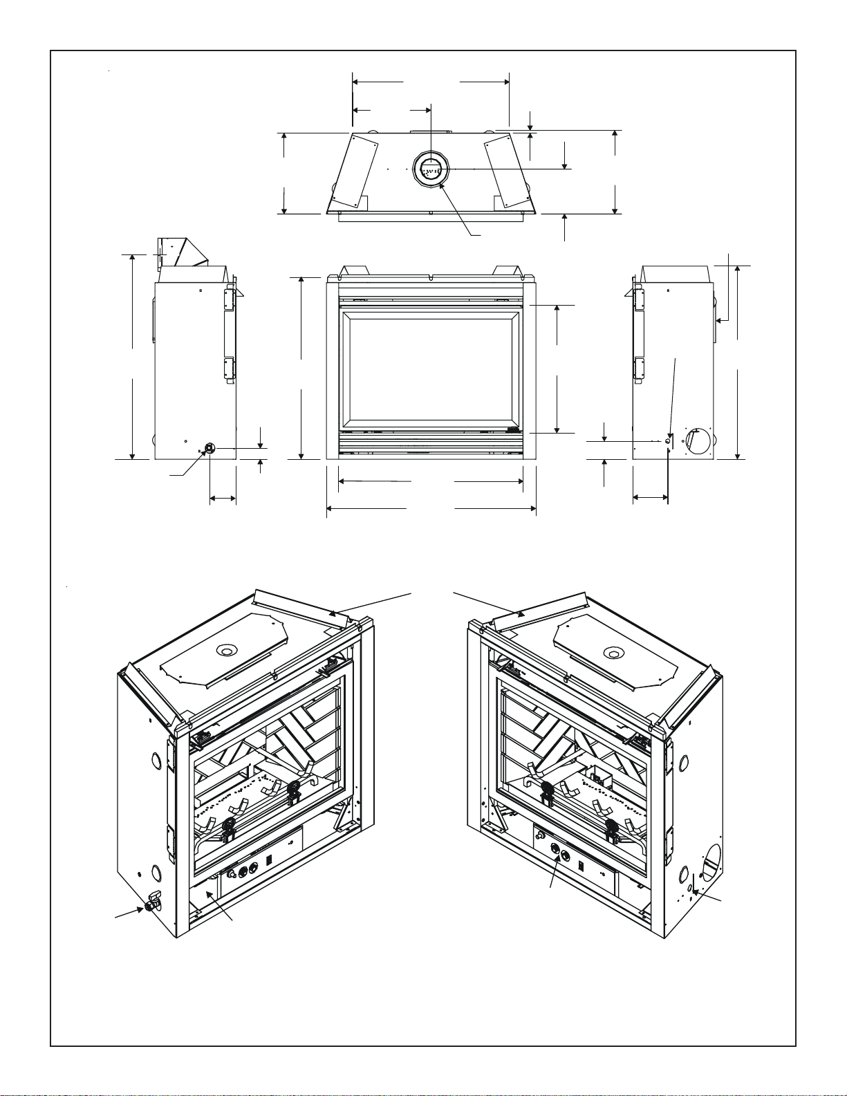
12 Quadra-fire • QV32B-A, QV36B-A • 2014-900 Rev. F • 9/06
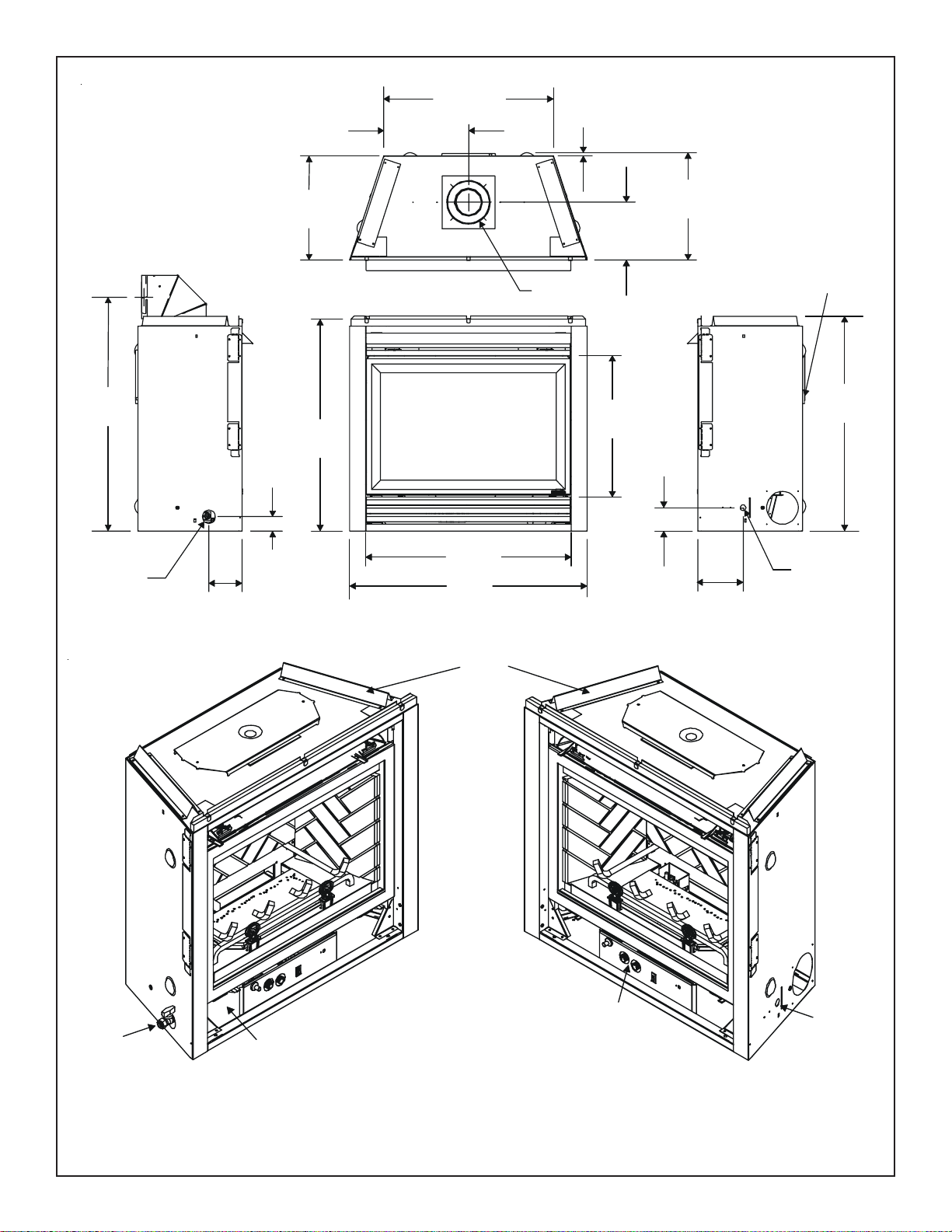
Figure 1. Diagram of the QV36B-A
30-11/16
(779mm)
1/2
(13mm)
15-5/16
(389mm)
16-3/8
(414mm)
8-3/4
(223mm)
Ø 6-5/8
(168mm)
15-7/8
(402mm)
37-3/4
(960mm)
ELECTRICAL
ACCESS
3-9/16
(90mm)
6-7/8
(174mm)
40-15/16
(1040mm)
36-1/8
(917mm)
35-5/8
(905mm)
25
(635mm)
40
(1016mm)
GAS LINE
ACCESS
2-1/8
(55mm)
5-1/16
(129mm)
Ø 8
(203mm)
TOP
STANDOFFS
GAS
CONTROLS
ELECTRICAL
ACCESS
GAS
ACCESS
RATING PLATE/
LABELS
13Quadra-fire • QV32B-A, QV36B-A • 2014-900 Rev. F • 9/06
Figure 2. Diagram of the QV32B-A
TOP
STAN DOFFS
GAS
CONTROLS
ELECTRICAL
ACCESS
GAS
ACCESS
RATING PLATE/
LABELS
Ø6-5/8
(168mm)
25-11/16
(653mm)
12-7/8
(326mm)
1/2
(13mm)
16-3/8
(414mm)
8-13/16
(223mm)
15-7/8
(402mm)
3-1/3
(90mm)
32-9/16
(828mm)
Ø8
(203mm)
21-7/16
(545mm)
6-7/8
(174mm)
ELECTRICAL
ACCESS
32-1/8
(815mm)
31-1/8
(790mm)
36
(913mm)
2-1/8
(55mm)
35-7/16
(901mm)
GAS LINE
ACCESS
5-1/16
(129mm)
 Loading...