

Quadra-Fire HUDBAY-FS, Hudson Bay Owner's Manual
R
HUDSON BAY
O-T L
Tested and
Listed by
Portland
Oregon USA
OMNI-Test Laboratories, Inc.
C
US
DIRECT VENT GAS APPLIANCE
Owner’s Manual
Installation and Operation
Model:
HUDBAY-FS
CAUTION
DO NOT DISCARD THIS MANUAL
• Important operating and
maintenance instructions
included.
WARNING:Iftheinformationinthese
instructionsisnotfollowedexactly,are
orexplosionmayresultcausingproperty
damage,personalinjury,ordeath.
• Do not store or use gasoline or other ammable vapors and liquids in the vicinity of this
or any other appliance.
• Whattodoifyousmellgas
- D o n o t t r y t o l i g h t a n y a p p l i a n c e .
Do not touch any electrical switch. Do not
use any phone in your building.
- Immediately call your gas supplier from a
neighbor’s phone. Follow the gas supplier’s
instructions.
- If you cannot reach your gas supplier, call
the re department.
• Installation and service must be performed
by a qualied installer, service agency, or the
gas supplier.
Installation and service of this appliance should be
performed by qualied personnel. Hearth & Home
Technologies suggests NFI certied or factory-trained
professionals, or technicians supervised by an NFI
certied professional.
• Read, understand and
follow these instructions
for safe installation and
operation.
DO NOT
DISCARD
• Leave this manual with
party responsible for use
and operation.
WARNING
HOT SURFACES!
Glass and other surfaces are hot during
operation AND cool down.
Hotglasswillcauseburns.
• Do not touch glass until it is cooled
• NEVER allow children to touch glass
• Keep children away
• CAREFULLY SUPERVISE children in same room as
replace.
• Alert children and adults to hazards of high temperatures.
Hightemperaturesmayigniteclothingorotherammable
materials.
• Keep clothing, furniture, draperies and other ammable
materials away.
In the Commonwealth of Massachusetts:
• installation must be performed by a licensed plumber or gas
tter.
See Table of Contents for additional Commonwealth of Massachusetts requirements.
This appliance may be installed as an OEM installation in
manufactured home (USA only) or mobile home and must be
installed in accordance with the manufacturer's instructions and
the manufactured home construction and safety standard, Title
24 CFR, Part 3280 or Standard for Installation in Mobile Homes,
CAN/CSA Z240MH.
This appliance is only for use with the type(s) of gas indicated
on the rating plate.
Page 1
Quadra-Fire • Hudson Bay • 7003-121 Rev. Q • 8/13
and Welcome to the Quadra-Fire Family
!
Hearth & Home Technologies welcomes you to our tradition
of excellence! In choosing a Quadra-Fire appliance, you
have our assurance of commitment to quality, durability, and
performance.
This commitment begins with our research of the market,
including ‘Voice of the Customer’ contacts, ensuring we
make products that will satisfy your needs. Our Research
and Development facility then employs the world’s most
advanced technology to achieve the optimum operation of
our stoves, inserts and replaces. And yet we are old-fashioned when it comes to craftsmanship. Each appliance is
SAMPLE OF SERIAL NUMBER / SAFETY LABEL
LOCATION: ON FRONT PANEL OF APPLIANCE
Test Lab & Report No.
Model Name
meticulously fabricated and gold and nickel surfaces are
hand-nished for lasting beauty and enjoyment. Our pledge
to quality is completed as each model undergoes a quality
control inspection. From design, to fabrication, to shipping:
Our guarantee of quality is more than a word, it’s QuadraFire tradition, and we proudly back this tradition with a Limited Lifetime Warranty.
We wish you and your family many years of enjoyment in the
warmth and comfort of your hearth appliance. Thank you for
choosing Quadra-Fire.
MODEL / MODÈLE
O-T L
US
C
OMNI-Test Laboratories, Inc.
061-S-29b-5
Portland
Oregon USA
Tested and
Listed by
Report No. / Rapport Numéro
APPROVED FOR CANADA AND USA TO:
ANSI Z21.88-2002 / CSA 2.33-2002 Vented Gas Fireplace Heaters, and
applicable sections of UL307b Gas Burning Heating Appliances for Manufactured
Homes and Recreational Vehicles, CAN/CGA 2.17-M91 “Gas Fired Appliances
for use at High Altitudes.”
This appliance is manufactured for operation with Natural Gas.
For conversion to propane use Manufacturer’s conversion kit and instructions
supplied with the appliance. This appliance may be installed in a bedroom or
bedsitting room; in Canada remote thermostat installation is required.
This vented gas fireplace heater is not for use with air filters.
This appliance must be installed in accordance with the current Standard
CAN/CSA Z240 MH, Mobile Housing, or with Manufactured Home Construction
and Safety Standard, Title 24 CFR, Part 3280, or when such standard is not
applicable, ANSI/NCSBCS A225.1/NFPA 501A, Manufactured Home Installation
Standard.
Warning: do not operate the appliance until all sections have been assembled
and installed in accordance with the manufacturer's instructions.
Warning: improper installation, adjustment, alteration, service or maintenance
can cause injury or property damage. Refer to the owner’s information manual
provided with this appliance. For assistance or additional information consult
a qualified installer, service agency or the gas supplier.
Warning: operation of this appliance when not connected to a properly installed
and maintained venting system can result in carbon monoxide (co) poisoning
and possible death.
Warning: operation of this appliance when not connected to a properly installed
and maintained venting system or tampering with the blocked vent shutoff
system can result in carbonmonoxide (co) poisoning and possible death.
Caution: hot while in operation. Do not touch. Severe burns may result. Keep
children, clothing, furniture, gasoline and other liquids having flammable vapors
away.
Caution: do not operate this appliance with glass removed, cracked or broken.
Replacement of the panel(s) should be done by a licensed or qualified person.
DO NOT REMOVE THIS LABEL / NE PAS ENLEVER L’ÉTIQUETTE
Made in U.S.A. / Fait Aux États-Unis
HUDSON BAY
VENTED GAS FIREPLACE HEATER
NOT FOR USE WITH SOLID FUEL
FOURNAISE AU GAZ AVEC VENTILATION
NE PAS UTILISER AVEC LE COMBUSTIBLE SOLIDE
R
7571 215th Street
Lakeville, MN 55044
APPROUVÉ POUR LE CANADA ET LES ÉTATS-UNIS:
ANSI Z21.88-2002 / CSA 2.33-2002 Fournaises au Gaz avec Ventilation, et
les sections applicable de UL 307b Appareils de Chauffage Au Gaz pour les
Maisons Mobiles et les Véhicules Motorisés, CAN/CGA 2.17-M91 “Gas Fired
Appliances for use at High Altitudes”.
Cet appareil est manufacturé pour l’opération avec le Gaz Naturel.
Pour une conversion au gaz propane les pièces du Manufacturier Cet appareil
peut être utilisé dans une chambre à coucher ou salle de séjour; au Canada,
l’installation d’un thermostat à distance est exigée.
Cet appareil de chauffage au gaz n’est pas pour l’usage avec des filtres d’air.
Installer l'appareil selon la norme CAN/CSA-Z240, Serie MM, Maisons mobiles,
ou la norme 24 CFR Part 3280, Manufactured Home Construction and Safety
Standard. Si ces normes ne sont pas pertineutes, utilisez la norme
ANSI/NCSBCS A225.1/NFPA 501A, Manufactured Home Installations
Standard.
Avertissement: ne pas utiliser l'appareil tant que toutes les sections n'ont pas
ete assemblees et installees selon les instructions du fabricant.
Avertissement: une installation, un ajustement, une altération, un service ou
un entretien incorrects peuvent causer des dommages matériels. Référez-vous
au manuel d’information fourni avec cet appareil. Pour assistance ou des
informations supplémentaires consultez un installateur qualifié, une agence
de service ou un fournisseur de gaz.
Avertissement: l’opération de cet appareil lorsqu’il n’est pas connecté à un
système de ventilation correctement installé et maintenu peut résulter à un
empoisonnement d’oxyde de carbone ou même de mort possible.
Advertissement l'operation de cet appareil lorsqu'il n'est pas conneclé à un
système de ventilation proprement nstallé ou si le systeme de lementure de
ventilation a été altéré, cela peut résulter à un empoisonnement d'oyxde de
carbone ou même de perte de vie.
Attention: chaud lorqu’il est en opération. Ne touchez pas. Des brûlures
sévères peuvent en résulter. Gardez les enfants, les vêtements, les meubles,
la gazoline et les autres liquides de vapeur inflammable êloignés.
Attention: cet appareil ne doit pas être opéré si la vitre est brisée, craquée
ou enlevée. Le remplacement du panneau doit être fait par une personne
licensée et qualifiée.
www.quadrafire.com
SAMPLE
Model / Modèle: HUDSON BAY
Serial / Série:
7003-951
Serial Number
APPROUVÉ POUR LE CANADA ET LES ÉTATS-UNIS:
ANSI Z21.88-2002 / CSA 2.33-2002 Fournaises au Gaz avec Ventilation, et les
sections applicable de UL 307b Appareils de Chauffage Au Gaz pour les Maisons
Mobiles et les Véhicules Motorisés, CAN/CGA 2.17-M91 “Gas Fired Appliances
for use at High Altitudes”.
Cet appareil est manufacturé pour l’opération avec le Gaz Naturel.
Pour une conversion au gaz propane les pièces du Manufacturier Cet appareil
peut être utilisé dans une chambre à coucher ou salle de séjour; au Canada,
l’installation d’un thermostat à distance est exigée.
Usage Au Gaz Naturel Usage Au Gaz Propane
"0-2000’ "0-2000’
Puissance Évaluée à “HI” (BTU/Hr) ....................42,000 ...............................40,500
Puissance Évaluée à "LO" (BTU/Hr)...................28,000 ............................... 31,000
Orifice du Brûleur Principal....................................125"................................... .076"
Pression Minimum de la Valve (pouces W.C.)...... 4.5".....................................11"
Pression Maximum de la Valve (pouces W.C.)..... 7.0".....................................14"
Pression du Collecteur d’ Échappement
à “HI” (pouces W.C.) .............................................3.5"..................................... 10"
Cet appareil est équipé pour les altitudes de 0-2000’ (0-610m) aux États-Unis; et au Canada
pour les altitudes de 0-4500’ (0-1370m). Pour les altitudes au dessus de 2000’ aux États-Unis,
la configuration du ventilateur, son orifice ou les deux peuvent possiblement avoir à être changé.
Voyez le manuel du propriétaire pour les informations sur ces changements.
Veuillez lire les instructions d'installation et d'opération qui accompagnent cet apareil.
Cet appareil doit être installé selon les codes locaux, s'il-y-a-lieu (et approuvé par dans la
République de Massachusetts); sinon suivez les codes THE NATIONAL FUEL GAZ ANSI
Z223.1; ou les codes Canadian Installation Codes CAN/CGA-B149.
REMARQUE: Le conduit gaz doit être installé conformément aux codes de construction locaux.
L'installation doit être effectuée par un technicien qualifeé et/ou muni d'une licence de manière
à respecter les règlements municipaux. (Dans la République de Massachusetts, l'installation
doit être effectuée par un plombier ou un installateur d'appareils à gaz agrée.)
Gardez le brûleur et le compartiment de contrôle propres. Vérifiez les instructions d’installation
et d’opération qui accompagnent cet appareil.
ESPACE MINIMUM AUX COMBUSTIBLES
Espaces minimum exigés de la construction combustible aux surfaces de l’appareil.
A. Dessus de fourneau au mur latéral..............................228.6 mm
B. Du coté du poêle au coté du mur.................................244.5 mm
C. En arrière du fourneau au mur latéral..........................25.4 mm
D. Du coin arrière du poêle au mur de coté.....................101.6 mm
E. Hauteur minimum d'alcove du plancher au plafond.....1372 mm
F. Profondeur maximum de l'alcove................................914.4 mm
G. Largeur minimum de l'alcove.......................................1181 mm
H. Dessus de fourneau au plafond...................................533.4 mm
CHEMINÉE: Un coussinet non-combustible de cheminée n’est pas exigé. Cependant, le plancher
en dessous du poêle doit être droit, à niveau et assez fort pour supporter le poêle sans le hasard
de basculer.
Cet appareil doit être utilisé seulement avec le gaz indiqué sur l’étiquette enregistré et peut être
installé dans une maison mobile en place permanente dans les endroits permis par les codes
locaux. Voyez le manuel du propriétaire pour des détails supplémentaires. Cet appareil ne doit
pas être converti avec des autres gaz sans l’utilisation d’un ensemble de conversion certifié.
Évaluation du Ventilateur Électrique: 115 V., 1.5 Amps, 60 Hz, 150 Watts
Fourniture Électrique: 120 Volts, 1.2 Amps, 60 Hz
Efficacité Thermique Jusqu'à: 84.02% NG (avec ventilateur allumé) 85.71% LP (avec ventilateur allumé)
P.4.1-02 Le canada tuyau minimum: 64.03% NG / 65.43% LP
VENTILATEUR CIRCULATOIRE
APPROVED FOR CANADA AND USA TO:
ANSI Z21.88-2002 / CSA 2.33-2002 Vented Gas Fireplace Heaters, and
applicable sections of UL307b Gas Burning Heating Appliances for Manufactured
Homes and Recreational Vehicles, CAN/CGA 2.17-M91 “Gas Fired Appliances
for use at High Altitudes.”
This appliance is manufactured for operation with Natural Gas.
For conversion to propane use Manufacturer’s conversion kit and instructions
supplied with the appliance. This appliance may be installed in a bedroom or
bedsitting room; in Canada remote thermostat installation is required.
For use with Natural Gas For use with Propane
"0-2000’ "0-2000’
Input Rate on “HI” (BTU/Hr) ................................42,000 .................................40,500
Input Rate on “LO” (BTU/Hr)...............................28,000 ................................. 31,000
Main Burner Orifice (DMS)................................... .125"......................................076"
Minimum Inlet Pressure (Inches W.C.)..................4.5" .......................................11"
Maximum Inlet Pressure (Inches W.C.).................7.0" .......................................14"
Manifold Pressure on “HI” (Inches W.C.) ..............3.5"....................................... 10"
This appliance equipped for altitudes 0-2000’ (0-610m) in USA; and in Canada for altitudes of
0-4500’ (0-1370m). In USA for Altitudes above 2000’, the vent configuration, orifice, or
combination of both may need to be changed. See Owner’s Manual for information on making
these changes.
This appliance must be properly connected to a venting system in accordance with the
manufacturer's installation instructions.
This appliance must be installed in accordance with local codes, if any (and Commonwealth
of Massachusetts approved); if none, follow the National Fuel Gas Code, ANSI Z223.1 or
Canadian Installation Codes, CAN/CGA-B149.
NOTE: Have the gas supply line installed in accordance with local building codes by a qualified
installer approved and/or licensed as required by the locality. (In the Commonwealth of
Massachusetts, installation must be performed by a licensed plumber or gas fitter.)
Keep burner and control compartment clean. See installation and operating instructions
accompanying this appliance.
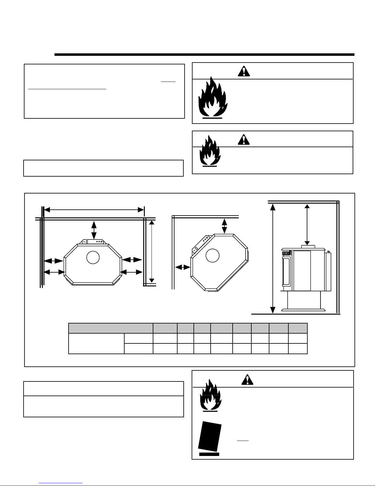
MINIMUM CLEARANCES TO COMBUSTIBLES
Minimum clearances required from combustible construction for all appliance surfaces.
A. Top of stove to side wall ....................................9 in.
B. Side of stove to side wall...................................9 5/8 in.
C. Back of stove to side wall..................................1 in.
D. L/H & R/H corner to side wall.............................4 in.
E. Min. alcove floor to ceiling height.......................54 in.
F. Maximum alcove depth......................................36 in.
G. Minimum alcove width....................................... 46-1/2 in.
H. Top of stove to ceiling........................................21 in.
HEARTH: A non-combustible hearth pad is not required. However, the floor beneath the stove
must be stable, level, and strong enough to support the stove without a tipping hazard.
This appliance is only for use with the type of gas indicated on the rating plate and may be
installed in an aftermarket, permanently located, manufactured (mobile) home where not
prohibited by local codes. See owner's manual for details. This appliance is not convertible for
use with other gases, unless a certified kit is used.
Blower Electrical Rating : 115 V., 1.5 Amps, 60 Hz, 150 Watts
Electrical Supply: 120 Volts, 1.2 Amps, 60 Hz
Thermal Efficiency up to: 84.02% NG (blower on) 85.71% LP (blower on)
P.4.1-02 Canada Minimum pipe: 64.03% NG / 65.43% LP
FAN TYPE VENTED CIRCULATOR
7003-950
Page 2
Quadra-Fire • Hudson Bay • 7003-121 Rev. Q • 8/13

- TABLE OF CONTENTS -
Section 1: Listing and Code Approvals
A. Appliance Certications ......................4
B. Glass Specications ............................4
C. BTU Specications ..............................4
D. High Altitude Installations ....................4
E. Non-Combustible Materials .................4
F. Combustible Materials ........................4
G. Electrical Codes .................................. 4
H. Requirements for the
Commonwealth of Massachusetts ...... 5
Section 2: Getting Started
A. Design & Installation
Considerations ....................................6
B. Tools and Supplies Needed................6
C. Inspect Appliance & Components ....... 6
Section 3: Appliance Location & Clearances
A. Selecting Appliance Location..............7
B. Clearances to Combustibles ...............7
Section 4: Termination Locations
A. Vent Termination Minimum
Clearances..........................................8
Section 7: Electrical Information
A. Recommendation for Wire ..................26
B. Connecting to the Appliance ...............26
C.
Section 8: Appliance Setup
A. Remove Shipping Materials ................28
B. Accessories .........................................28
C. Door Crown Installation .......................28
D. Grille Installation .................................29
E. Brick Installation ..................................29
G. Mineral Wool ....................................... 31
H. Blower Installation ............................... 32
I. Damper Adjustment ............................33
J. Shutter Adjustment .............................33
K. Glass Replacement .............................33
Section 9: Operating Instructions
A. Before Lighting Appliance ...................34
B. Controls ...............................................34
C. Lighting Appliance ...............................35
D. After Appliance is Lit ...........................36
E. Frequently Asked Questions ...............36
Section 10: Troubleshooting ...............................37
Standing Pilot Ignition System Wiring
F. Positioning the Logs ............................30
.. 26
Section 5: Vent Information
A. Venting Components ..........................10
B. Use of Elbows .....................................10
C. Measuring Standards .......................... 10
D. How to Use the Vent Graph ................11
E. Venting Guidelines ..............................11
F. Horizontal Termination ........................12
G. Vertical Termination ............................ 15
Section 6: Gas Information
A. Fuel Conversions ................................22
B. Gas Pressures .................................... 24
C. Gas Connection.. ................................25
= Contains updated information.
Section 11: Maintaining & Servicing Appliance
A. Maintenance Tasks .............................40
Section 12: Reference Materials
A. Appliance Dimension Diagram ...........41
B. Vent Components Diagram ................42
C. Vent Components List ........................43
D. Service Parts List ................................44
E. Warranty .............................................47
F. Contact Information ............................49
Quadra-Fire • Hudson Bay • 7003-121 Rev. Q • 8/13
Page 3
1
Listing and Code Approvals
A. Appliance Certication
MODEL: Hudson Bay
LABORATO RY:
TYPE: Direct Vent Gas Heater
STANDARD:
The product is listed to ANSI standards for “Vented Gas Appliance Heaters” and applicable sections of “Gas Burning
Heating Appliances for Manufactured Homes and Recreational Vehicles” and "Gas Fired Appliances for use at High
Altitudes".
Manufactured Home or Mobile Home installation may occur
only after the home is site located and must conform with
the Manufactured Home Construction and Safety Standard,
Title 24 CFR, Part 3280, or, when such a standard is
not applicable, the Standard for Manufactured Home
Installations, ANSI/NCSBCS A225.1, or Standard for Gas
Equipped Recreational Vehicles and Mobile Housing, CSA
Z240.4.
When installed, the appliance must be electrically grounded
in accordance with local codes or, in the absence of local
codes, with the National Electrical Code, ANSI/NFPA 70, or
the Canadian Electrical Code, CSA C22.1.
OMNI Test Laboratories, Inc.
061-S-29b-5
ANSI Z21.88-2002
UL307bּCAN/CBA 2.17-M91
ּCSA 2.33-2002ּ
B. Glass Specications
This appliance is equipped with 5mm ceramic glass. Replace
glass only with 5mm ceramic glass. Please contact your
dealer for replacement glass.
NOTE: This installation must conform with local codes. In the
absence of local codes you must comply with the National
Fuel Gas Code, ANSI Z223.1-latest edition in the U.S.A.
and the CAN/CGA B149 Installation Codes in Canada.
WARNING
Do NOT use this appliance if any part has been under water.
Immediately call a qualied service technician to inspect
the unit and to replace any part of the control system and
any gas control which has been under water.
C. BTU Specications
Model
(US or Canada)
Hudson Bay
(NG)
Hudson Bay
(LP)
* Thermal efciency maximum pipe with blower on.
** Canada minimum pipe.
Maximum
Input
BTU
42,000 28,000 .125 84.02 64.03
40,500 31,000 .076 85.71 65.43
Minimum
Input
BTU
Orice
Size
(DMS)
*Steady
State
Efciency
%
**P.4
%
D. High Altitude Installations
Omni-Test Laboratories listed gas appliances are tested and
approved without requiring changes for elevations from 0 to
2000 feet in the U.S.A. and 0 to 4500 feet in Canada.
When installing this appliance at an elevation above 2000
feet, it may be necessary to decrease the input rating by
changing the existing burner orice to a smaller size. Input
rate should be reduced by 4% for each 1000 feet above a
2000 foot elevation in the U.S.A. If the heating value of the
gas has been reduced, these rules do not apply. To identify
the proper orice size, check with the local gas utility.
If installing this appliance at an elevation above 4500 feet (in
Canada), check with local authorities.
E. Non-Combustible Materials
Materials that are reported as passing ASTM E 136,
Standard Test Method for Behavior of Materials in a Vertical
Tube Furnace at 750°C, shall be considered non-combustible
materials.
F. Combustible Materials
Materials made of or surfaced with wood, compressed
paper, plant fibers, plastics, or other materials that can ignite
and burn, whether flame proofed or not, or whether plastered
or unplastered shall be considered combustible materials.
G. Electrical Codes
NOTICE: This appliance must be electrically wired and
grounded in accordance with local codes or, in the absence
of local codes, with National Electric Code ANSI/NFPA 70-
latest edition or the Canadian Electric Code CSA C22.1.
• A 110-120 VAC circuit for this product must be protected with
ground-fault circuit-interrupter protection, in compliance with
the applicable electrical codes, when it is installed in locations
such as in bathrooms or near sinks.
Page 4
Quadra-Fire • Hudson Bay • 7003-121 Rev. Q • 8/13

NOTE: The following requirements reference various
Massachusetts and national codes not contained in this
document.
H. Requirements for the Commonwealth of
Massachusetts
For all side wall horizontally vented gas fueled equipment
installed in every dwelling, building or structure used in whole
or in part for residential purposes, including those owned or
operated by the Commonwealth and where the side wall
exhaust vent termination is less than seven (7) feet above
nished grade in the area of the venting, including but not
limited to decks and porches, the following requirements
shall be satised:
Installation of Carbon Monoxide Detectors
At the time of installation of the side wall horizontal vented
gas fueled equipment, the installing plumber or gas tter shall
observe that a hard wired carbon monoxide detector with an
alarm and battery back-up is installed on the oor level where
the gas equipment is to be installed. In addition, the installing
plumber or gas tter shall observe that a battery operated or
hard wired carbon monoxide detector with an alarm is installed
on each additional level of the dwelling, building or structure
served by the side wall horizontal vented gas fueled equipment. It shall be the responsibility of the property owner to
secure the services of qualied licensed professionals for the
installation of hard wired carbon monoxide detectors.
In the event that the side wall horizontally vented gas fueled
equipment is installed in a crawl space or an attic, the hard
wired carbon monoxide detector with alarm and battery backup may be installed on the next adjacent oor level.
In the event that the requirements of this subdivision can not
be met at the time of completion of installation, the owner shall
have a period of thirty (30) days to comply with the above
requirements; provided, however, that during said thirty (30)
day period, a battery operated carbon monoxide detector with
an alarm shall be installed.
Approved Carbon Monoxide Detectors
Each carbon monoxide detector as required in accordance
with the above provisions shall comply with NFPA 720 and
be ANSI/UL 2034 listed and IAS certied.
Signage
A metal or plastic identication plate shall be permanently
mounted to the exterior of the building at a minimum height
of eight (8) feet above grade directly in line with the exhaust
vent terminal for the horizontally vented gas fueled heating
appliance or equipment. The sign shall read, in print size no
less than one-half (1/2) inch in size, “GAS VENT DIRECTLY
BELOW. KEEP CLEAR OF ALL OBSTRUCTIONS.”
Inspection
The state or local gas inspector of the side wall horizontally
vented gas fueled equipment shall not approve the installation unless, upon inspection, the inspector observes carbon
monoxide detectors and signage installed in accordance with
the provisions of 248 CMR 5.08(2)(a) 1 through 4.
Exemptions
The following equipment is exempt from 248 CMR 5.08(2)(a)
1 through 4:
The equipment listed in Chapter 10 entitled “Equipment
•
Not Required To Be Vented” in the most current edition of
NFPA 54 as adopted by the Board; and
Product Approved side wall horizontally vented gas fueled
•
equipment installed in a room or structure separated from
the dwelling, building or structure used in whole or in part
for residential purposes.
MANUFACTURER REQUIREMENTS
Gas Equipment Venting System Provided
When the manufacturer of Product Approved side wall
horizontally vented gas fueled equipment provides a venting system design or venting system components with the
equipment, the instructions provided by the manufacturer for
installation of the equipment and the venting system shall
include:
•
Detailed instructions for the installation of the venting system design or the venting system components; and
•
A complete parts list for the venting system design or
venting system.
Gas Equipment Venting System NOT Provided
When the manufacturer of a Product Approved side wall hor-
izontally vented gas fueled equipment does not provide the
parts for venting the ue gases, but identies “special venting systems”, the following requirements shall be satised by
the manufacturer:
•
The referenced “special venting system” instructions shall
be included with the appliance or equipment installation
instructions; and
•
The “special venting system” shall be Product Approved
by the Board, and the instructions for that system shall
include a parts list and detailed installation instructions.
A copy of all installation instructions for all Product Approved
side wall horizontally vented gas fueled equipment, all venting instructions, all parts lists for venting instructions, and/or
all venting design instructions shall remain with the appliance or equipment at the completion of the installation.
See Gas Connection section for additional Commonwealth of Massachusetts requirements.
Page 5Quadra-Fire • Hudson Bay • 7003-121 Rev. Q • 8/13
Getting Started
2
A
. Design & Installation Considerations
Quadra-Fire direct vent gas appliances are designed to
operate with all combustion air siphoned from outside of the
building and all exhaust gases expelled to the outside. No
additional air source is required.
CAUTION
Check building codes prior to installation.
• Installation MUST comply with local, regional, state
and national codes and regulations.
• Consult local building, re ofcials or authorities having
jurisdiction about restrictions, installation inspection,
and permits.
C. Inspect Appliance & Components
WARNING
Inspect appliance and components for
damage. Damaged parts may impair safe
operation.
• Do NOT install damaged components.
• Do NOT install incomplete components.
• Do NOT install substitute components.
Report damaged parts to dealer.
•
Carefully remove the appliance and components from
the packaging.
When planning an installation, it is necessary to determine
the following information before installing:
Where the appliance is to be installed.
•
•
The vent system conguration to be used.
• Gas supply piping.
• Electrical wiring.
• Whether optional accessories - devices such as a blower,
thermostat or remote control - are desired.
WARNING
Keep appliance dry.
• Mold or rust may cause odors.
• Water may damage controls.
B. Tools and Supplies Needed
Before beginning the installation be sure that the following
tools and building supplies are available. Note: Not all
tools will apply to every installation.
Reciprocating saw
Pliers
Hammer
Phillips Screwdriver
Flat Blade Screwdriver
Plumb Line
Level
Manometer
Tape Measure
Variable Speed Drill/Driver
Wrench Set
Framing Square
Framing Material
Voltmeter
Gloves
Safety Glasses
Non-corrosive Leak Check Solution
or combustible gas detector
Caulking material (300ºF minimum
continuous exposure rating)
• Remove cast door and glass door, and set aside on pro-
tective surface.
• Remove log set and component pack from rebox.
• Report to your dealer any parts damaged in shipment,
particularly the condition of the glass.
• Read all of the instructions before starting the instal-
lation. Follow these instructions carefully during the
installation to ensure maximum safety and benet.
WARNING
Hearth & Home Technologies disclaims any
responsibility for, and the warranty will be
voided by, the following actions:
• Installation and use of any damaged appliance or vent
system component.
• Modication of the appliance or vent system.
• Installation other than as instructed by Hearth & Home
Technologies.
• Improper positioning of the gas logs or the glass door.
• Installation and/or use of any component part not approved
by Hearth & Home Technologies.
Any such action may cause a re hazard.
Page 6
Quadra-Fire • Hudson Bay • 7003-121 Rev. Q • 8/13
3
Appliance Location and Clearances
NOTE:
· Illustrations reect typical installations and are FOR
DESIGN PURPOSES ONLY.
· Illustrations/diagrams are not drawn to scale.
· Actual installation may vary due to individual design
preference.
A. Selecting Appliance Location
When selecting a location for your appliance it is important to
consider the required clearances to walls (see Figure 3.1).
NOTE: For actual appliance dimensions refer to Section 12.
B. Clearances
D
B
WARNING
Fire Risk
Provide adequate clearance:
• Around air openings
• To combustibles
• For service access
Locate appliance away from trafc areas.
WARNING
Fire Risk.
• Locate and install appliance to all
clearance specications in manual.
F
H
A
E
Model A B C D E F G H
Hudson Bay
Figure 3.1
It is permissible to place the appliance on carpet.
A
E
Inches
Millimeters
C
9-5/8 1 36 46-1/2 9 4 54 21
219 25 91 118 229 102 137 533
CAUTION
Some carpet materials may be sensitive to radiant heat from the
appliance causing discoloration or odor.
NOTE: Flooring beneath appliance may reach 90 degrees
plus room ambient temperature. Check with flooring
manufacturer for maximum temperature allowed on flooring
surfaces.
F
G
WARNING
Fire Risk.
Odor Risk.
Tipping Risk
• Install appliance on a stable, level platform/
oor strong enough to support appliance
without tipping.
• USE wood ooring, ceramic tile, brick hearth
or high pressure laminate ooring applied
directly over the sub-ooring material.
Page 7Quadra-Fire • Hudson Bay • 7003-121 Rev. Q • 8/13
Termination Locations
HORIZONTAL
hH
Ft.
*
.25*
*
*
*
5
Over 14/12to16/12 ...........................................6.0
A B
4
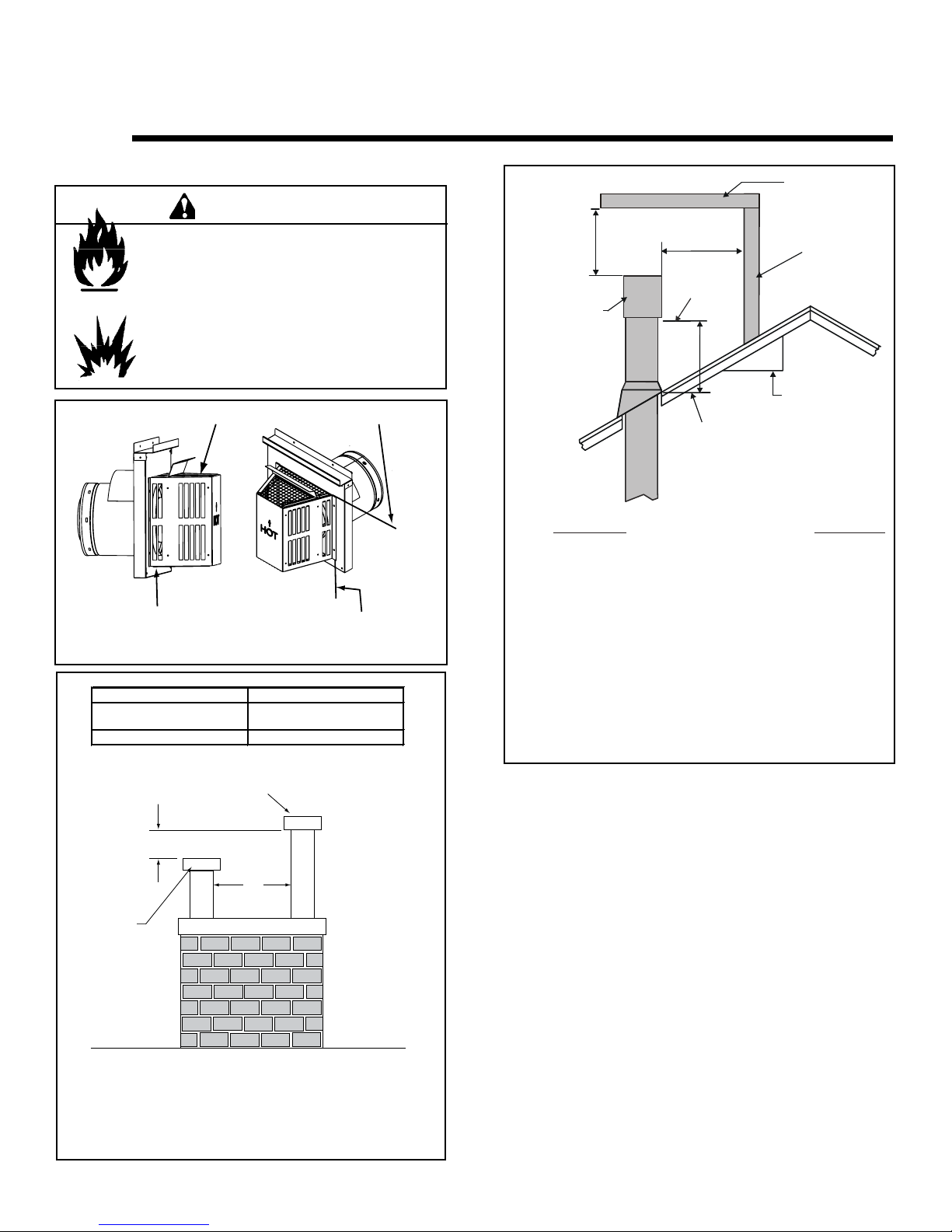
A. Vent Termination Minimum Clearances
WARNING
Fire Risk.
Explosion Risk.
Maintain vent clearance to combus-
tibles as specied.
• Do not pack air space with insulation or
other materials.
Failure to keep insulation or other materials
away from vent pipe may cause re.
Measure vertical clearances from this surface.
2 FT.
MIN.
GAS DIRECT VENT
TERMINATION CAP
OVERHANG
20 INCHES MIN.
LOWEST
DISCHARGE
OPENING
H (MIN.) - MINIMUM HEIGHT FROM ROOF
TO LOWEST DISCHARGE OPENING
X
12
ROOF PITCH
IS X/ 12
VERTICAL
WALL
Measure horizontal clearances from this surface.
(See Figure 4.4 for specic clearances.)
Figure 4.1 Termination Clearances
6 in. (minimum) up to 20 in.
152 mm/508 mm
20 in. and over 0 in. minimum
Gas, Wood or Fuel Oil
Termination Cap
B
A *
Gas
Termination
Cap **
18 in. minimum
457 mm
Roof Pitc
(Min.)
Flat to 6/12 .........................................................1.0
Over 6/12 to 7/12........................................................1
Over 7/12 to 8/12 ...............................................1.5
Over 8/12 to 9/12 ...............................................2.0
Over 9/12 to 10/12.............................................2.5
Over 10/12to11/12 ...........................................3.2
Over 11/12to12/12 ...........................................4.0
Over 12/12to14/12 ...........................................5.0
Figure 4.3 Minimum Height from Roof to Lowest Discharge
Opening
Figure 4.3 species minimum vent heights for various
pitched roofs.
If using decorative cap cover(s), this distance may need to be
*
increased. Refer to the installation instructions supplied with the
decorative cap cover.
In a staggered installation with both gas and wood or fuel oil
**
terminations, the wood or fuel oil termination cap must be
higher than the gas termination cap.
Figure 4.2 Multiple Vertical Termination
Page 8
Quadra-Fire • Hudson Bay • 7003-121 Rev. Q • 8/13
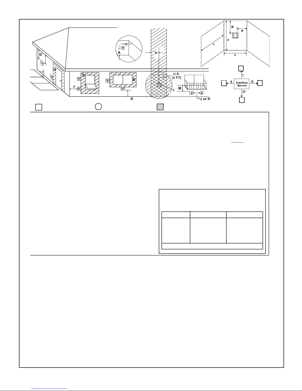
**
(See Note 2)
(S Note 2)
v
= VENT TERMINAL
V
A=12 inches ............. clearances above grade, veran-
(See Note 1)
X
= AIR SUPPLY INLET = AREAWHERE TERMINAL IS NOT PERMITTED
da, porch, deck or balcony
B=12 inches ............ clearances to window or door
that may be opened, or to permanently closed window. (Glass)
D* =18 inches ............. vertical clearance to unventilat-
ed soffitorto ventilatedsoffitlocated above theterminal
*30 inches ............ for vinyl clad soffits and below
electrical servic e
F=9 inches ..............clearance to outside corne r
G=6 inches ............... clearancetoinside corner
H=3ft. (Canada) ...... not to be installed above agas
meter/regulatorassembly within 3
feet (90cm) horizontally from the
center-line of the regulator
I
=3ft. .......................
clearance to gas service regulator vent outlet
J=9 inches (U.S.A.)
12 inches (Canada )clearance to non-mechanical air
supply inlettobuilding or the
combustion air inlet to any other
appliance
v
v
v
K=3 ft. (U.S.A.)
L**=7ft. ......................... clearanceabove paved
M***= 18 inches .............. clearance under veranda,
6ft. (Canada) ......... clearancetoamechanical
(powered) airsupply inlet
(See Note 1)
sidewalkor a paved driveway
located on public property
porch, deck, balcony or overhang
42 inches .............. vinyl
S= 6 inche s ................. clearancefromsides of
(See Note 3)
electrical service
T=12 inches ................ clearanceabove electrical
(See Note 3)
service
Alcove Applications
N=6 inches ................. non-vinyl sidewall s
P=8ft.
___________________________________________________________________
___________________________________________________________________
___________________________________________________________________
12 inches ............... vinyl sidewalls
Q
MIN
1cap 3feet2xQ
2caps6feet 1xQ
3caps9feet 2/3xQ
4caps12feet1/2 xQ
Q
=#terminationcap sx3R
MIN
=(2/#terminat ioncaps) xQ
MAX
R
MAX
ACTUAL
ACTUAL
ACTUAL
ACTUAL
ACTUAL
_
_
_
_
aventshall not terminatedirectlyabove asidewalkorpaved
driveway whichislocated betweentwo single family dwellings and
serves bothdwellings .
*only permittedifveranda, porch, deckorbalcony is fullyopenon
aminimum of 2sides beneaththe floor, or meetsNote2.
1: On private property where termination is less than 7 feet above
sidewalk, driveway, deck, porch, veranda or balcony, use of a listed
2: Te rminationinan alcove space (spaces only open on one side
an overhang) are permitted with the dimensions specified for
without
or non-vinyl siding and soffits. 1. There must be at least 3 feet
between termination caps. 2. All mechanical air intakes within
feet of a termination cap must be a minimum of 3 feet below the
cap. 3. All gravity air intakes within 3 feet of a termination cap
3: Location of the vent termination must not interfere with access
Figure 4.4
NOTE: Local codes or regulations may require different
clearances.
NOTE: Termination caps may be hot. Consider their proximity to
doors or other traffic areas.
WARNING: In the U.S.: Vent system termination is NOT permitted
in screened porches. You must follow side wall, overhang and
ground clearances as slated in the instructions.
In Canada: Vent system termination is NOT permitted in screened
porches. Vent system termination is permitted in porch areas with
two or more sides open. You must follow side wall, overhang and
ground clearances as stated in the instructions.
Quadra-Fire assumes no responsibility for the improper performance of the appliance when the venting system does not meet
these requirements.
CAUTION: IF EXTERIOR WALLS ARE FINISHED
WITH VINYL SIDING, IT IS SUGGESTED THAT A
VINYL PROTECTOR KIT BE INSTALLED (part #VPKDV).
Page 9Quadra-Fire • Hudson Bay • 7003-121 Rev. Q • 8/13
5
Vertical
Horizontal
12 in.
8-1/2 in.
8-1/2 in.
Vent Information
A. Venting Components
In order to comply with applicable codes and product
warranties, use only following venting components:
• Hearth & Home Technologies (HHT)
• Security Chimney's Secure Vent Chimney System
• Selkirk Metalbestos
• AmeriVent
• Simpson Dura-Vent (SDV)
DO NOT USE FIELD-FABRICATED VENTING
COMPONENTS. Refer to the venting manufacturer’s
instructions.
This product is approved to be vented either horizontally,
through the side wall or vertically through the roof. You may
vent through a Class A or masonry chimney if an approved
adapter is used.
This appliance is a direct vent heater. All combustion air must
come directly from the outside of the building. The vent pipe
for this unit consists of an inner and an outer pipe. The inner
pipe carries the appliance exhaust out of the system, and the
outer pipe brings fresh combustion air into the appliance.
B. Use of Elbows
CAUTION
ALL vent conguration specications MUST be followed.
• This product is tested and listed to these
specications.
• Appliance performance will suffer if specications are
not followed.
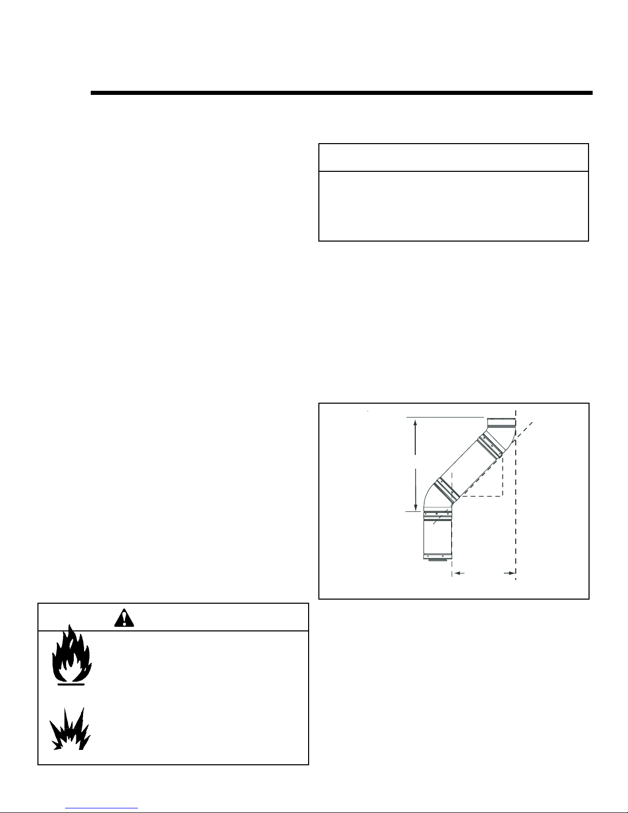
Diagonal runs have both vertical and horizontal vent aspects
when calculating the effects. Use the rise for the vertical
aspect and the run for the horizontal aspect. (See Figure
5.1.)
Two 45° elbows may be used in place of one 90° elbow. On
45° runs, one foot of diagonal is equal to 8-1/2 in. (216mm)
horizontal run and 8-1/2 in. (216mm) vertical run. A length of
straight pipe is allowed between two elbows. (See Figure
5.1.)
• A round support box/wall thimble or heat shield is
required when the venting passes through a combustible wall.
• A support box or ceiling restop is required when the
venting passes through a ceiling.
• Roof ashing and a storm collar are required when venting passes through the roof.
• Follow instructions provided with the venting for installation of these items.
WARNING
Fire Hazard.
Explosion Risk.
Asphyxiation Risk.
Do NOT connect this gas appliance to a chimney
ue serving a separate solid-fuel or gas burning
appliance.
• Vent this appliance directly outside.
• Use separate vent system for this appliance.
May impair safe operation of this appliance or
other appliances connected to the ue.
Figure 5.1
C. Measuring Standards
Vertical and horizontal measurements were made using the
following standards.
• Pipe measurements are from center line to center line.
• Horizontal terminations are measured to the outside of
the mounting surface (ange of termination cap). See
Figure 4.1 on page 8.
• Vertical terminations are measured to the top of the last
pipe before termination cap.
• Horizontal pipe installed level with 1/4 in. rise.
Page 10
Quadra-Fire • Hudson Bay • 7003-121 Rev. Q • 8/13
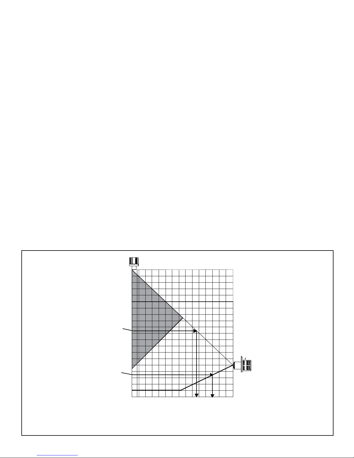
D. How to Use the Vent Graph E. Venting Guidelines
EX. 2
EX. 1
11" 2' 4' 6' 8' 10' 12' 14' 15'
30'
28'
26'
24'
22'
20'
18'
16'
14'
12'
10'
8'
6'
4'
2'
0'
(MAX)
(MIN)
40'
38'
36'
34'
32'
1. Measure the distance from the top of appliance to the
center of the 90° elbow. On the graph below, draw a
horizontal line from that measurement on the vertical
axis across until it intersects with the slanted line.
2. From the point of this intersection, draw a vertical line to
the bottom of the graph.
3. The point at which this line meets the bottom line of the
graph is the maximum length of the horizontal run.
Example 1: If the vertical dimension from the top of the
appliance is to the center of the 90° elbow is
7 ft. (2m), the horizontal run to the outer wall
flange must not exceed 12 ft. (4m).
Example 2: If the vertical dimension from the top of the
appliance is 21 ft. (6m), the horizontal run
to the outer wall flange must not exceed 9
ft. (3m).
4. Each 90° elbow is equivalent to 3 ft. (914mm) of vent
pipe and each 45° elbow is equivalent to 1 ft. (305mm)
of vent pipe, and must be subtracted from vent pipe
run. A single vertical to horizontal 90° elbow is already
calculated into the allowable 15 ft. (5m) run. Each
additional 90° elbow reduces the maximum horizontal
distance by 3 ft. (914mm).
NOTES
The maximum horizontal vent run is 15 ft. (5m) with a minimum
vertical vent rise of 10 ft. (3m).
The minimum horizontal vent run is 11 in. (279mm).
Minimum wall thickness is 4 in. (102mm). Maximum wall
thickness is 20 in. (508mm).
Horizontal sections require a 1/4 in. (6mm) rise for every 12
in. (305mm) of horizontal travel.
Exterior Vent Diameter = 6 5/8 in. (168mm); Inner Vent Diameter = 4 in. (101mm)
Horizontal sections require noncombustible support every 3
ft. (914mm), e.g. wall straps.
Maximum 90° elbows for horizontal termination is 3.
Maximum 90° elbows for vertical termination is 4.
NOTE: I F YOUR INSTALLATION FALLS WITHIN A SHADED
AREA ON THE GRAPH, THE DAMPER MUST BE USED.
(In the Commonwealth of Massachusetts, the word damper
shall be replaced with the words flue restrictor.)
Example: The use of 3 elbows would reduct the
alowable horizontal run to 9 ft. (3 - 1 = 2
elbows x 3 ft. = 6 ft.; 15 ft. max. - 6 ft. = 9
ft. max.)
Figure 5.2
VERTICAL DISTANCE
FROM APPLIANCE TO
TO THE 90° ELBOW
TOTAL HORIZONTAL RUN TO OUTSIDE OF EXTERIOR WALL (INCLUDING ELBOWS)
Page 11Quadra-Fire • Hudson Bay • 7003-121 Rev. Q • 8/13
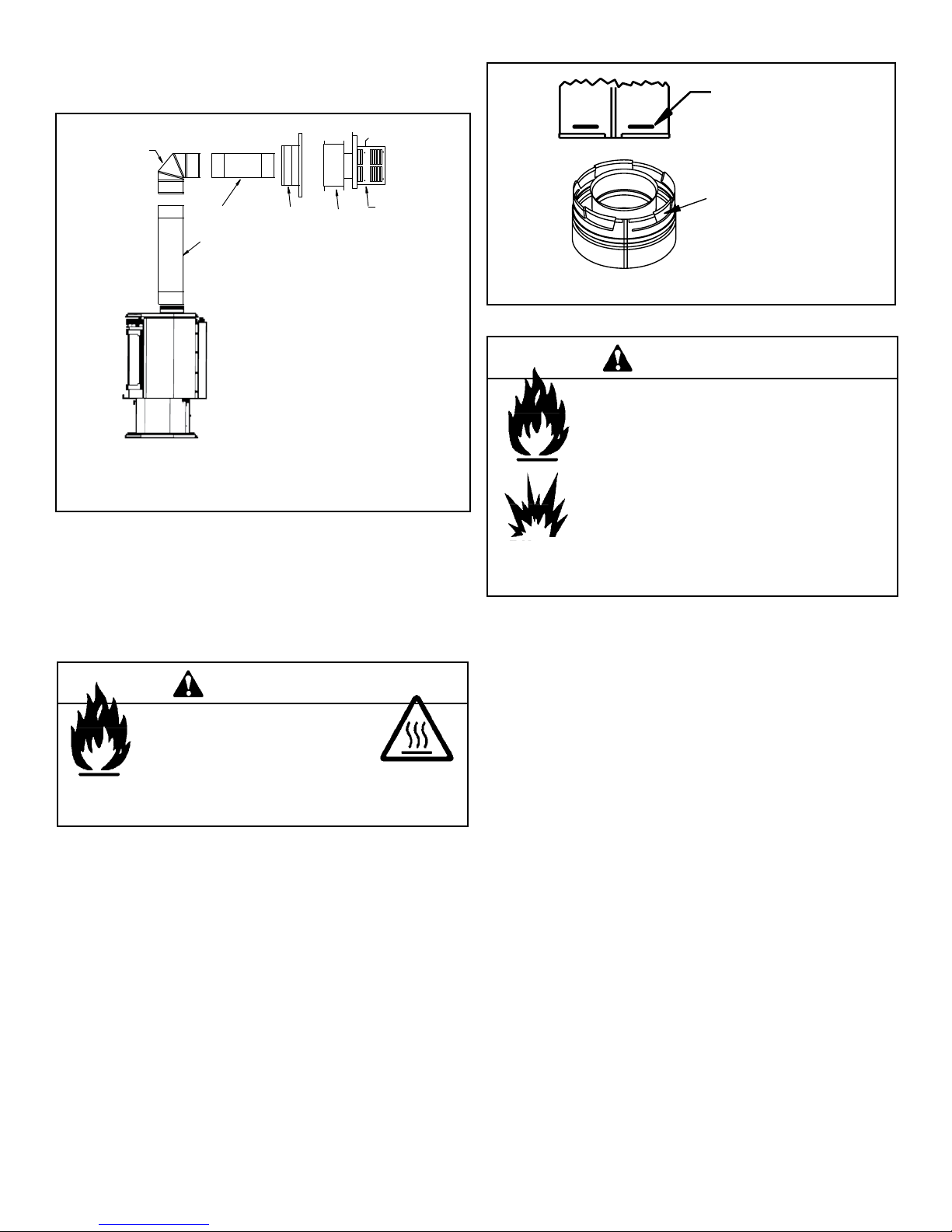
F. Horizontal Termination
90 DEGREE
ELBOW
PIPE LENGTH
PIPE LENGTH
WALL
THIMBLE
COVER
HHW2 Recommended
for optimum
performance.
WALL
THIMBLE
Figure 5.3
Step 1.
Determine the desired location of the appliance. Check to
ensure that wall studs or roof rafters are not in the way when
the venting system is attached. If this is the case, you may
want to adjust the location of the appliance.
WARNING
Fire Hazard.
Exhaust Fume Risk.
Impaired Performance of Appliance.
• Ensure vent components are locked together correctly.
• Pipe may separate if not properly joined.
Female Locking Lugs
Male Locking Lugs
Figure 5.4
WARNING
Fire Risk.
Explosion Risk.
Combustion Fume Risk.
Use vent run supports per installation instructions.
Connect vent sections per installation instructions.
• Maintain all clearances to combustibles.
• Do NOT allow vent to sag below connection
point to appliance.
• Maintain specied slope (if required).
Improper support may allow vent to sag or separate.
Step 3.
For installations using a support box/wall thimble (check
pipe manufacturer's instructions), mark the wall for a 10 in.
x 10 in. (254mm x 254mm) square hole. The center of
the square hole should line up with the center line of the
horizontal pipe, as shown in Figure 5.5, on the next page.
Cut and frame the hole in the exterior wall where the vent will
be terminated. If the wall being penetrated is constructed of
noncombustible material, i.e. masonry block or concrete, a
7 in. (178mm) diameter hole is acceptable.
Step 2.
Direct vent pipe is designed with a locking connection. To
connect the venting system to the appliance flue outlet, a
twist-lock adapter is built into the appliance at the factory.
Remember to include wall thickness in minimum clearances
when figuring the measurements for your installation
needs.
Note: Direct vent pipe is designed to slide straight onto
the male ends of adjacent pipes and fittings by orienting the
pipe indentations so they match and slide into the entry slots
on the male ends, see Figure 5.4. Push the pipe sections
completely together, then twist-lock one section clockwise
approximately one-quarter turn, until the two sections are
fully locked. The female locking lugs may not be visible from
the outside, on the pipe or fittings. They may be located by
examining the inside of the female ends.
Page 12
Quadra-Fire • Hudson Bay • 7003-121 Rev. Q • 8/13
HOT
WOOD
SCREW
WALL THIMBLE
PART HHW2 PART
841-0670 (Preferred)
Figure 5.6
8 in.
(203mm)
7 in.
(178mm)
7 in.
(178mm)
6 in.
(152mm)
CENTER
LINE
CENTER
LINE
CENTER OF
HOLE
WALL
THIMBLE
NOTES:
(1) The four wood screws provided should be replaced with
appropriate fasteners for stucco, brick, concrete, or
other types of sidings.
Figure 5.5
NOTE:
(1) Installation requires a minimum of 6 in. (152mm)
horizontal run of vent with a 1/4 in. (6mm) rise run towards
the termination. Each 1 ft. (305mm) of horizontal venting
must include a 1/4 in. (6mm) rise. Never allow the vent
to run downward. This could cause high temperatures
and may present the possibility of a house or structure
fire.
(2) The location of the horizontal vent termination on an
exterior wall must meet all local and national building
codes, and must not be easily blocked or obstructed,
see Figure 4.4 on page 8.
(3) For installations requiring a vertical rise on the exterior
of the building, the HHT RHVK snorkel kit (Part #844-
8921) is available with a 14 in. (356mm) and a 36 in.
(914mm) tall snorkel termination cap. Follow the
same installation procedures as used for standard
horizontal terminations. If the snorkel termination must
be installed below grade (i.e. basement application),
proper drainage must be provided to prevent water from
entering the snorkel termination. Do not backfill around
snorkel termination.
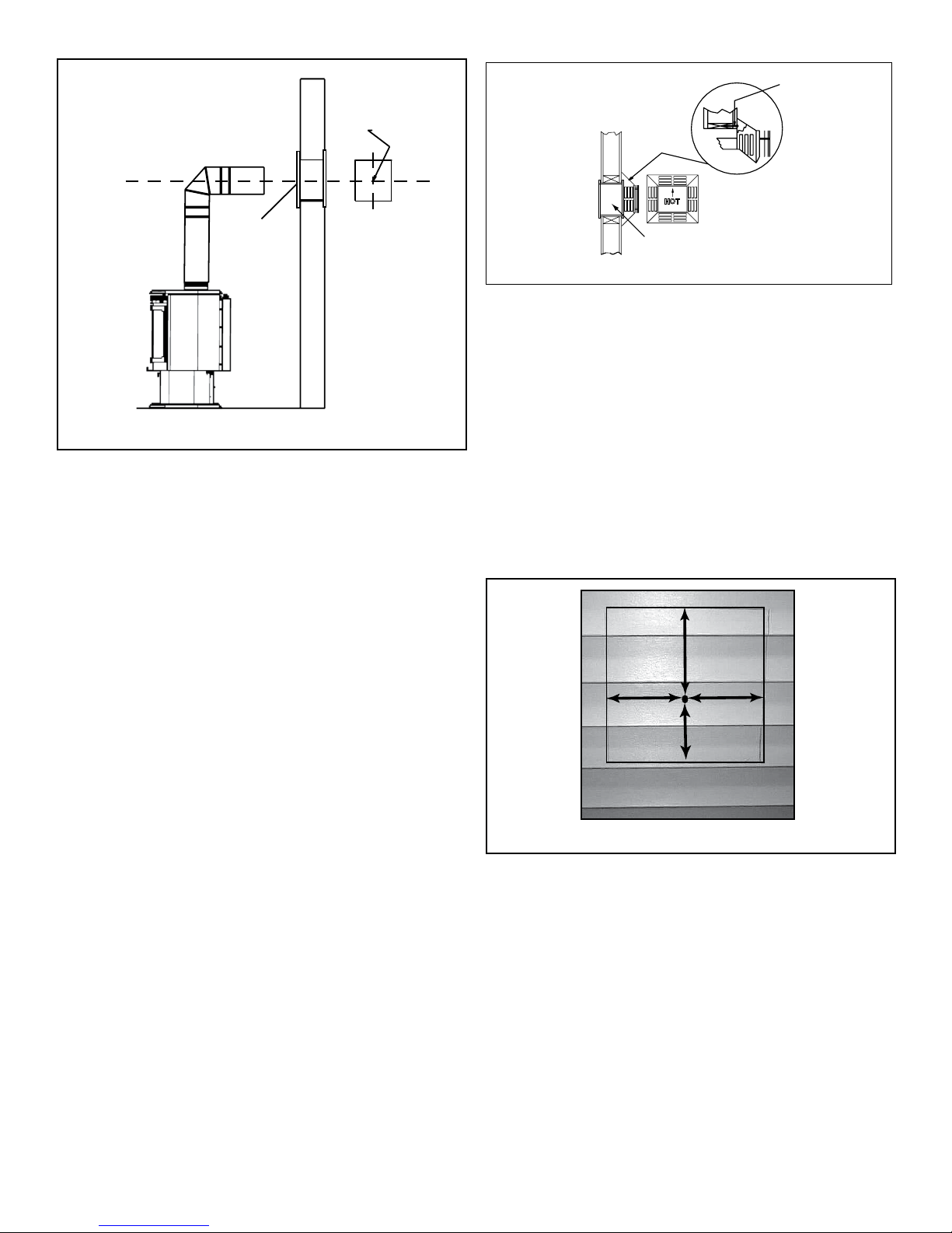
Step 4.
Position the horizontal termination cap in the center of the 10
in. x 10 in. (254mm x 254mm) square hole and run a bead
of non-hardening mastic around its outside edges, so as to
make a seal between it and the wall, attach termination cap
to the exterior wall with the four wood screws provided. The
arrow on the vent cap should be pointing up (Figure 5.6).
(2) Termination cap HHW2 (Part #841-0670) is highly
recommended on a building with vinyl siding, as the
vinyl siding standoff is built in. The pilot hole will be 2 in.
(51mm) closer to the bottom of the square than the top.
Using a framing square, draw a 14 in. x 14 in. (356mm x
356mm) square around the pilot hole in the siding. See
Figure 5.7.
Figure 5.7
(NOTE: If you are installing termination cap HHW2, the
pipe will be off center on the flashing). Ensure that proper
clearances to combustible materials are maintained. If
you are using an approved termination cap other than
HHW2 on a building with vinyl siding, a vinyl siding
standoff should be installed between the vent cap and
the exterior wall (Figure 5.8, on the next page). Attach
the vinyl siding standoff to the horizontal termination
cap. The vinyl siding standoff prevents excessive heat
from possibly melting the vinyl siding material. The vent
termination cap shall not be recessed into a wall or
siding. Remove siding from the area where the standoff
will be located.
Page 13Quadra-Fire • Hudson Bay • 7003-121 Rev. Q • 8/13
WALL THIMBLE
COVER
WALL THIMBLE
VINYL SIDING
STANDOFF WITH
SIDING BENEATH
REMOVED
SCREWS
BOLT HORIZONTAL
TOP TO VINYL
STANDOFF
SCREWS
APPLY SEALANT
TO ALL FOUR
SIDES
VINYL SIDING
Figure 5.8
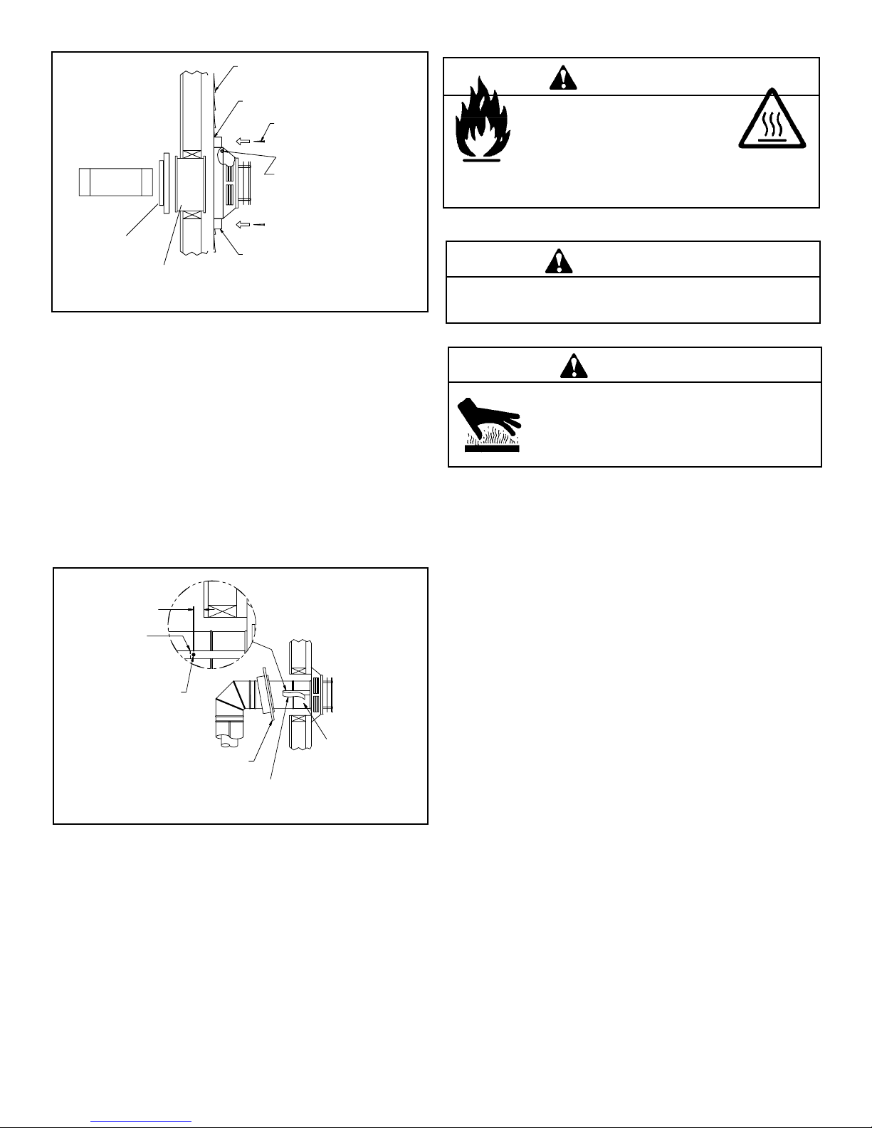
Step 5.
Place the wall thimble cover over the pipe assembly and
slide the appliance and vent assembly towards the wall,
carefully inserting the vent pipe into the vent termination
cap assembly. It is important that the vent pipe extend into
the vent termination cap a sufficient distance so as to result
in a minimum pipe overlap of 1-1/4 in. (32mm). Secure the
connection between the vent pipe and the vent termination
cap by attaching the two sheet metal strips extending from
the vent termination cap assembly into the outer wall of
the vent pipe. Use the two sheet metal screws provided to
connect the strips to the pipe section (Figure 5.9).
WARNING
Fire Hazard.
Exhaust Fume Risk.
Impaired Performance of Appliance.
• Ensure vent components are locked together correctly.
• Pipe may separate if not properly joined.
WARNING
Do NOT connect a pipe section to a termination cap without
using the telescoping ue section found on the termination cap.
WARNING
Burn Risk.
• Local codes may require installation of a cap
shield to prevent anything or anyone from
touching the hot cap.
1/4 in. (6mm)
FOLD STRAP
HERE
SHEET METAL SCREW
Figure 5.9
WALL THIMBLE COVER/CEILING
FIRESTOP AS REQUIRED BY
LOCAL JURISDICTION
STRAP
WALL
THIMBLE
Note: The attachment from the vent pipe to the vent
termination cap must be sealed with silicone. Termination
caps shall not be recessed into a wall or siding.
Page 14
Quadra-Fire • Hudson Bay • 7003-121 Rev. Q • 8/13
PLUMBER'S TAPE
CONNECTED TO
WALL STRAP
WALL
STRAP
TWO 45 DEGREE
ELBOWS
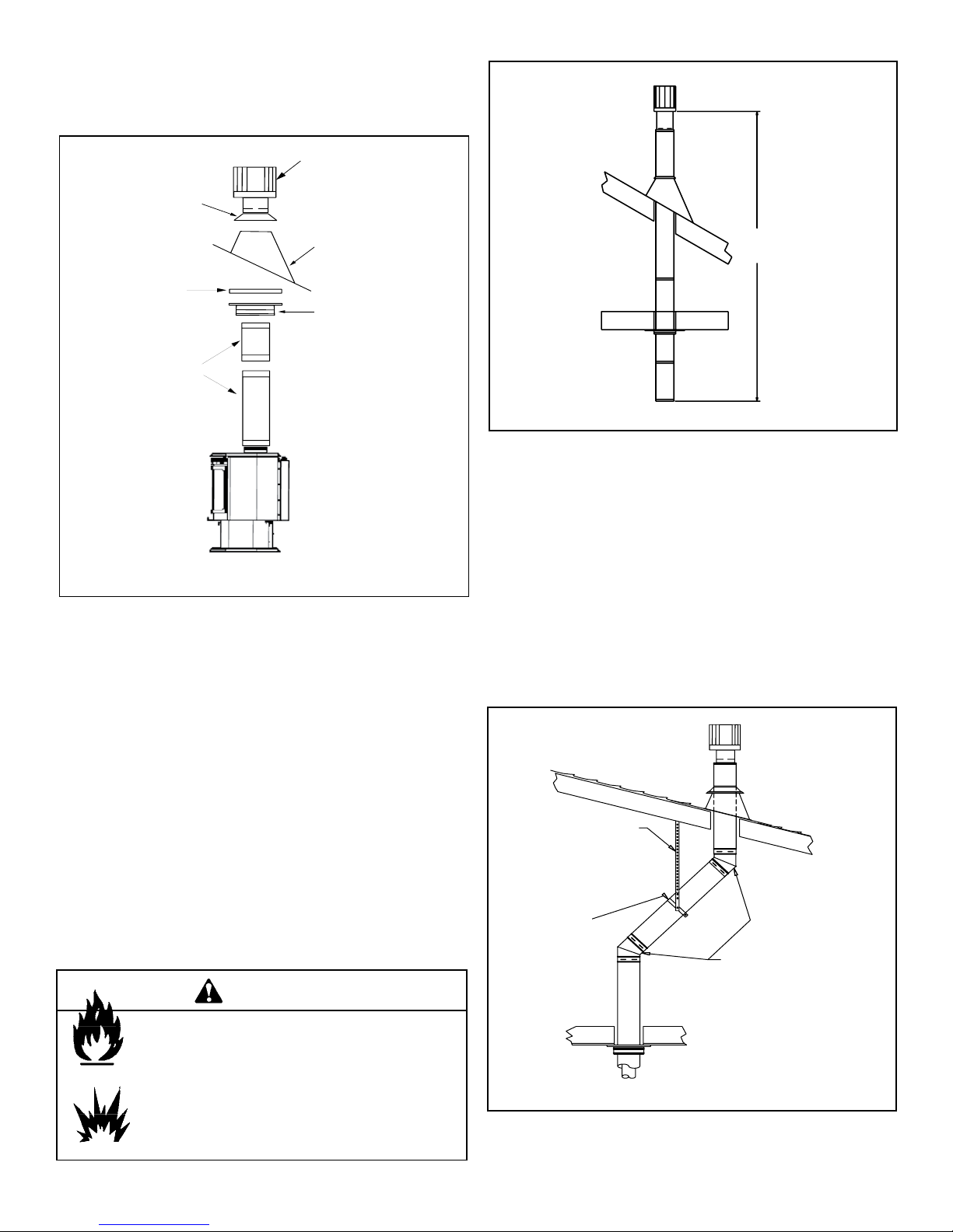
G. Vertical Termination
VERTICAL
TERMINATION
CAP
STORM
COLLAR
FLASHING
FIRESTOP
PIPE
LENGTH
SUPPORT
BOX
1. Direct Vent Pipe
Figure 5.10
Step 1.
Check the installation instructions for required 1 in. (25mm)
clearances (air space) to combustibles when passing
through ceilings, walls, roofs, enclosures, attic rafters, or
other nearby combustible surfaces. See page 17, Figure
5.16. Check the instructions below for maximum vertical rise
of the venting system, and any maximum horizontal offset
limitations. All offsets must fall within the set parameters of
the vent graph (Figure 5.2) located on page 11.
NOTE: Maximum vertical rise allowable is 40 ft. (12m) See
Figure 5.11.
40 ft. (12m)
MAXIMUM
Figure 5.11
Step 2.
Set the gas appliance in its desired location. Drop a plumb
bob down from the ceiling to the position of the appliance
flue exit, and mark the location where the vent will penetrate
the ceiling. Drill a small hole at this point. Next, drop a plumb
bob from the roof to the hole previously drilled in the ceiling,
and mark the spot where the vent will penetrate the roof.
Determine if ceiling joists, roof rafters, or other framing will
obstruct the venting system. You may wish to relocate the
appliance, or to offset, as shown in Figure 5.12 to avoid
cutting loadbearing members. When location is determined,
drill small hole.
NOTE: Maximum number of 45° elbows permitted for a
vertical installation is eight, provided their installation
does not decrease maximum allowable horizontal run (as
specified by vent graph, on page 11).
Fire Risk.
Explosion Risk.
Maintain vent clearance to combustibles as speci-
ed.
• Do not pack air space with insulation or other
materials.
Failure to keep insulation or other materials away
from vent pipe may cause re.
WARNING
Figure 5.12
Page 15Quadra-Fire • Hudson Bay • 7003-121 Rev. Q • 8/13
 Loading...