

Quadra-Fire GRAND-MBK-AU Owner's Manual
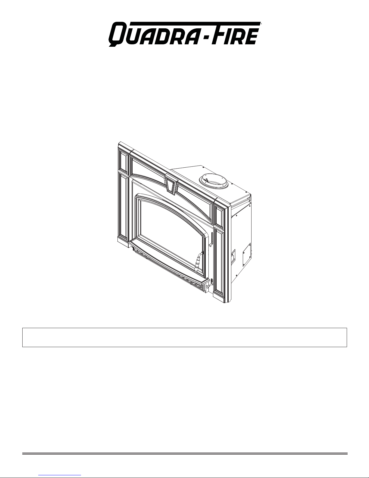
VOYAGEUR GRAND INSERT
Automatic Combustion Control (ACC)
OWNER’S MANUAL
Installation and Operations
Model:
GRAND-MBK-AU
INSTALLATIONS TO COMPLY WITH AS/NZS2918:2001
AND WILL REQUIRE A BUILDING CONSENT
IMPORTANT: Read all instructions carefully before starting installation. Failure to follow these
instructions may result in a fi re hazard and will void the warranty.
• Fig. 3,4,5,6, 7 and Table 1,2,3,4 relate to installations with tested fl ue systems; as per AS/NZS
2918:2001 - Appendix F, with a ceiling angle between 0° - 30° inclusive.
• For installations with a ceiling angle greater than 30°, refer to Fig. 18.1, 21.1 & 21.2 and AS/NZS
2918:2001 4.6.3(b)
• Ceiling Plate may vary in size depending on ceiling angle. Please specify ceiling pitch prior to
ordering the ceiling plate.
• Quadra-Fire Voyageur Grand ACC wood burner’s are tested and approved to the N.Z. National
Environmental Standards;
GRAND-MBK-AU Voyageur Grand Insert Hardwood Certifi ed
Particulate Emissions = 2.0 g/kg Space Heating Effi ciency = 62.8%
Page 1
7075-205B
October 12, 2015
Voyageur Grand
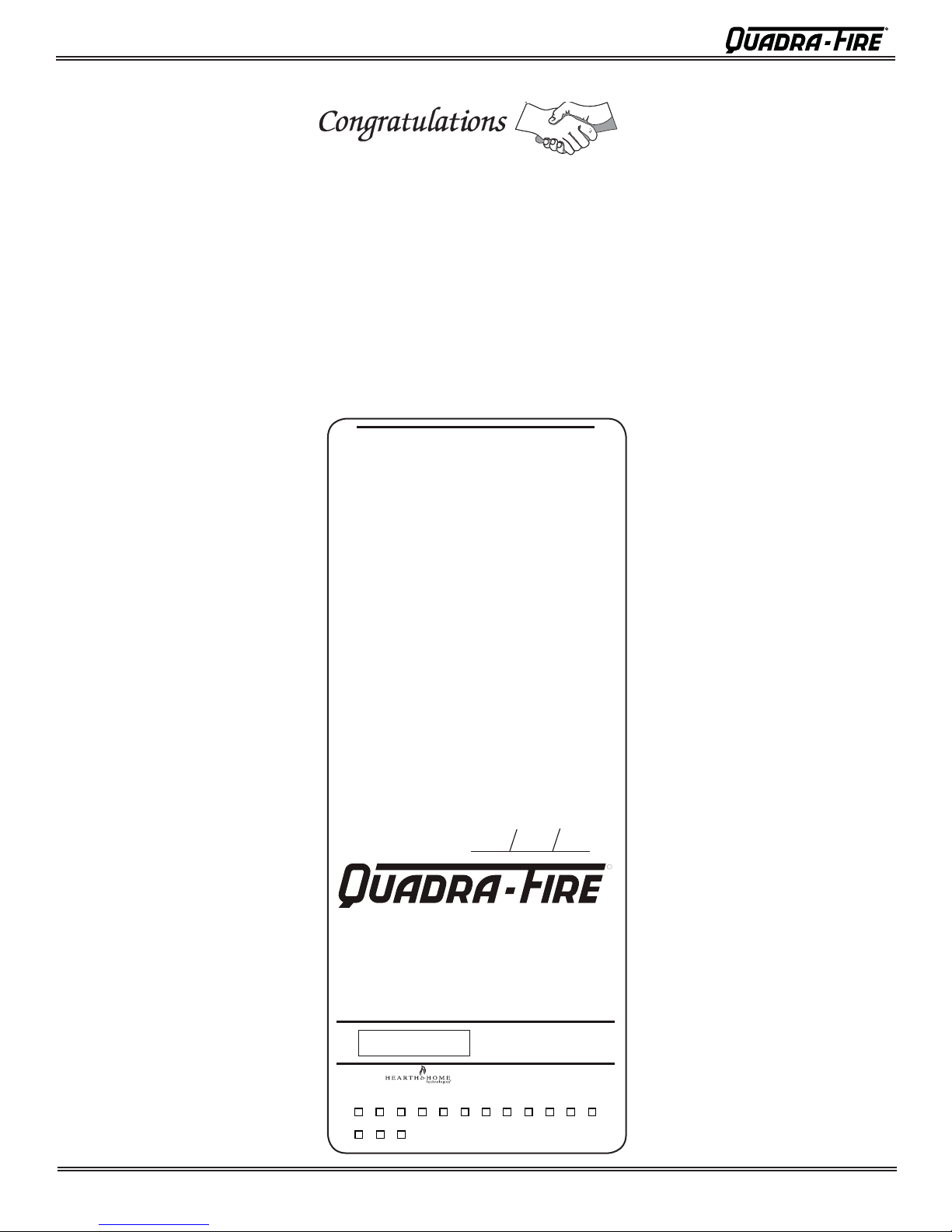
and Welcome to the Quadra-Fire Family!
Hearth & Home Technologies welcomes you to our tradition
of excellence! In choosing a Quadra-Fire appliance, you
have our assurance of commitment to quality , durability , and
performance.
This commitment begins with our research of the market,
including ‘Voice of the Customer’ contacts, ensuring we
make products that will satisfy your needs. Our Research
and Development facility then employs the world’s most
advanced technology to achieve the optimum operation of
VOYAGEUR GRAND
OVERALL AVERAGE EFFICIENCY BURNING HARD-
(WHEN TESTED IN ACCORDANCE TO AS/NZS 4012)
AVERAGE PARTICULATE EMISSION FACTOR BURN-
ING HARDWOOD
(WHEN TESTED IN ACCORDANCE TO AS/NZS 4013)
2.0 g/kg
MAXIMUM AVERAGE HEAT OUTPUT BURNING
HARDWOOD
our stoves, inserts and fi replaces. And yet we are old-fash-
ioned when it comes to craftsmanship. Each unit is meticulously fabricated and surfaces are hand-fi nished for lasting
beauty and enjoyment. Our pledge to quality is completed
as each model undergoes a quality control inspection.
We wish you and your family many years of enjoyment in
the warmth and comfort of your hearth appliance. Thank
you for choosing Quadra-Fire.
WOOD
62.8%
9.3 kw
BURN ONLY HARDWOOD WITH A MOISTURE CON-
APPROVED FUEL
TENT LESS THAN 25% (dry basis).
WETBACK - ALL MODELS
MANUFACTURED BY
Wetbacks are NOT an approved option and must
not be tted.
NOTE: Performance may vary from test values
depending on actual operating conditions.
INSTALLATION DATE
VOYAGEUR GRAND INSERT
This appliance has been TESTED TO AS/NZS4013 for
Serial No.
007057
Mfg by:
U.S. ENVIRONMENTAL PROTECTION AGENCY - Export stove. May not be operated within the United States
JAN FEB MAR APR MAY JUN JUL AUG SEP OCT NOV DEC
2013
Hardwood by VIPAC LTD.
Report # 30A-13-0025-TRP-331382-0
Date tested: March 2013
1445 N. Highway, Colville, WA 99114 www.quadrafire.com
2014 2015
DO NOT REMOVE THIS LABEL
Made in U.S.A. of US and
imported parts.
7075-206
R
Page 2
7075-205B
October 12, 2015

Voyageur Grand
Safety Alert Key:
• DANGER! Indicates a hazardous situation which, if not avoided will result in death or serious injury.
• WARNING! Indicates a hazardous situation which, if not avoided may result in death or serious injury.
• CAUTION! Indicates a hazardous situation which, if not avoided, may result in minor or moderate injury.
• NOTICE: Indicates practices which may cause damage to the appliance or to property.
TABLE OF CONTENTS
Congratulations ...............................................................2
Serial Number Label ........................................................2
User’s Guide
Section 1: Operating Instructions
A. Quick Start Guide ..............................................4
B. Automatic Combustion Control (ACC) ..............5
C. Air Controls .......................................................5
D. Burn Rates and Operating Effi ciency ................5
E. Blower Control Box Snap Disc Operations .......5
F. Blower Operating Instructions ...........................5
Section 2: Maintenance & Service
A. Disposal of Ashes .............................................7
B. Chimney and Chimney Connector
Inspection/Cleaning...........................................7
C. Appliance Inspection - Routine .........................7
D. Cleaning Plated Services ..................................7
E. Glass Cleaning ..................................................8
F.
G. Quick Reference Maitenance Guide .................9
H. Trouble Shoot Guide .........................................10
Section 3: Service Parts Replacement
A. Glass Replacement ...........................................11
B. Snap Disc Replacement....................................11
C. Wiring Diagram .................................................11
D. Blower Replacement .........................................12
E. Door Handle Assembly .....................................13
F. Baffl e & Ceramic Blanket Removal ...................13
G. Tube Channel Assembly Replacement .............14
Inspect Firebrick & Replacement Instructions ...8
Installer’s Guide
Section 4: Getting Started
A. Tools and Supplies Needed ..............................15
B. Fire Safety .........................................................15
C. Inspect Appliance and Components
and Pre-Burn Checklist .....................................15
Section 5: Dimensions and Clearances
A. Appliance Dimensions.......................................16
B. Clearances to Combustibles (UL and ULC)
and Hearth Protection Requirements ................17
C. Alternate Floor Protection Calculation...............18
Section 6: Chimney Systems
A. Venting Systems ...............................................19
B. Inspections ........................................................19
C. Larger Chimneys ...............................................19
D. Masonry Chimney .............................................19
E. Prefabricated Metal Chimney ............................19
F. Installation into a Masonry Fireplace.................20
G. Installation into a Factory Built Fireplace ..........20
Section 7: Appliance Set-up
A. Outside Air Installation ......................................22
B. Optional Elbow Flue Adapter Installation ..........23
C. Securing Stove Pipe/Liner to Flue Collar ..........23
D. Leveling Legs ....................................................23
E. Securing Appliance to Stove Pipe/Liner ............24
F. Standard Surround & Trim Installation ..............24
G. Standard Surround & Cast Trim, .......................25
H. All Cast Surround ..............................................26
I. Blower Cord Installation - Left Side ...................26
Section 8: Reference Materials
A. Warnings ...........................................................29
B. Warranty Policy .................................................30
C. Contact Information ...........................................32
October 12, 2015
7075-205B
Page 3
Voyageur Grand
H
WARNING! Risk Of Fire
1
Operating Instructions
1
User’s Guide
A. Quick Start Guide
FIRST FIRE ITEMS NEEDED:
OPEN AIR
CONTROLS
HIGH
LOW
START-UP
AIR
Push In and then Pull Out
BURN
RATE
Upper
right
corner
Lower
right
corner
1
ADD KINDLING
LIGHT THE PAPER
Note: These are generic drawings and may not represent
your specifi c model.
10 Pieces of Newspaper, 10-20 Pieces of Dry Kindling
and a Few Pieces of Dry Split Wood.
LOAD WOOD
ADD NEWSPAPER
2
W ARNING! Risk Of Fire
DO NOT LEAVE UNATTENDED
During startup, if additional draft is needed,
allow the door to remain open approximately1/2 inch. Once the draft is established,
close and securely latch the door to prevent:
• Spillage of smoke, fl ame and carbon
monoxide
• Spillage of sparks, coals and logs
• Over-fi ring
DO NOT leave the stove unattended with the door open
4
3
5
ADD MORE WOOD &
SECURELY LATCH THE DOOR
Page 4
6
REDUCE AIR
CONTROL
Set to desired heat
output
HIG
LOW
BURN RATE CONTROL
Upper Right Corner
7
7075-205B
The stove is ready for
normal operation.
October 12, 2015
Voyageur Grand
B. Automatic Combustion Control (ACC)
Typically , when you build a fi re, you open the air controls fully
and monitor the fi re to prevent it from going into an overfi re
situation and/or burning your wood up too quickly before you
shut down the air controls to the desired burn rate.
When using the Automatic Combustion Control (ACC) system,
you do not have to continually monitor the fi re. Once you
set the ACC system it will control the fi re for you. Follow the
instructions below to learn how to operate your stove with
ease.
C. Air Controls
1. Start-Up Air Control
The function of the Start-Up Air Control is to activate the
Automatic Combustion Control system (ACC).
• Push the Start-Up Air Control all the way back until it stops
and then pull forward to the front of the appliance until it
stops. Figure 5.1.
• The air channel opens and allows air to enter the front of
the appliance for approximately 20-25 minutes.
• The air channel gradually shuts down until it is completely
closed at the end of the 20-25 minutes.
• The fi re is now controlled by the air supplied by the Burn
Rate Air Control. Figure 5.1.
• This function should be performed each time you reload
the appliance.
2. Burn Rate Air Control
• The air supply enters at the upper front of the fi rebox,
near the top of the glass door.
• This preheated air supplies the necessary fresh oxygen
to mix with the unburned gases, helping to create the
second, third and fourth combustion process.
• This air is regulated by the Burn Rate Air Control.
• There are four settings High, Medium-High, Medium-Low
and Low.
• When the control is raised all the way up it is on the High
setting and when pushed all the down it is on the Low
setting.
Burn Rate Control
ACC Start-up
Air Control
To activate: Push back until it stops
and then pull forward until it stops
Figure 5.1 Start-up and Burn Rate Air Controls
HIGH
LOW
D. Burn Rates and Operating Effi ciency
For maximum operating effi ciency
1. Burn dry, well-seasoned wood.
2. Follow these burn rate instructions below and refer to
Figure 5.1.
*NOTE:
These are guidelines. Actual settings may vary with
type of wood, chimney draft, altitude and other variables.
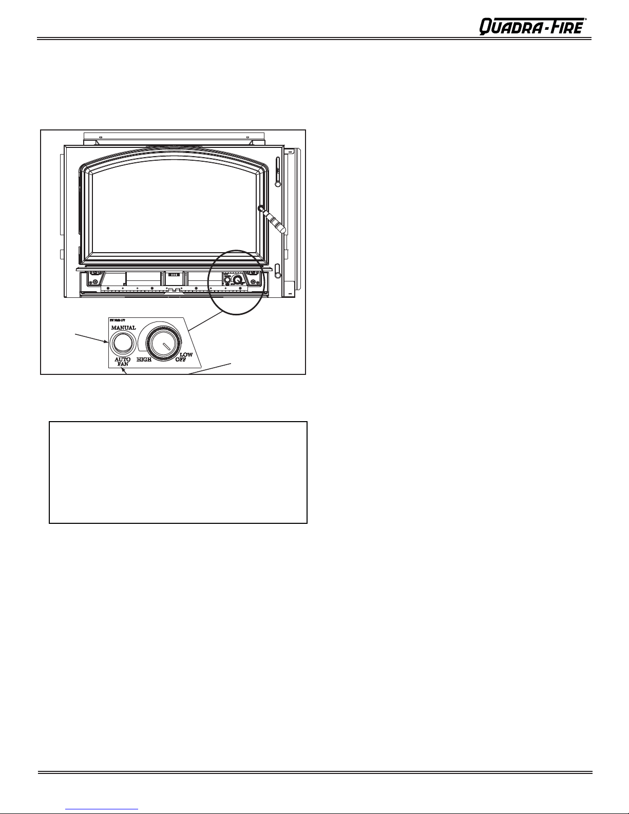
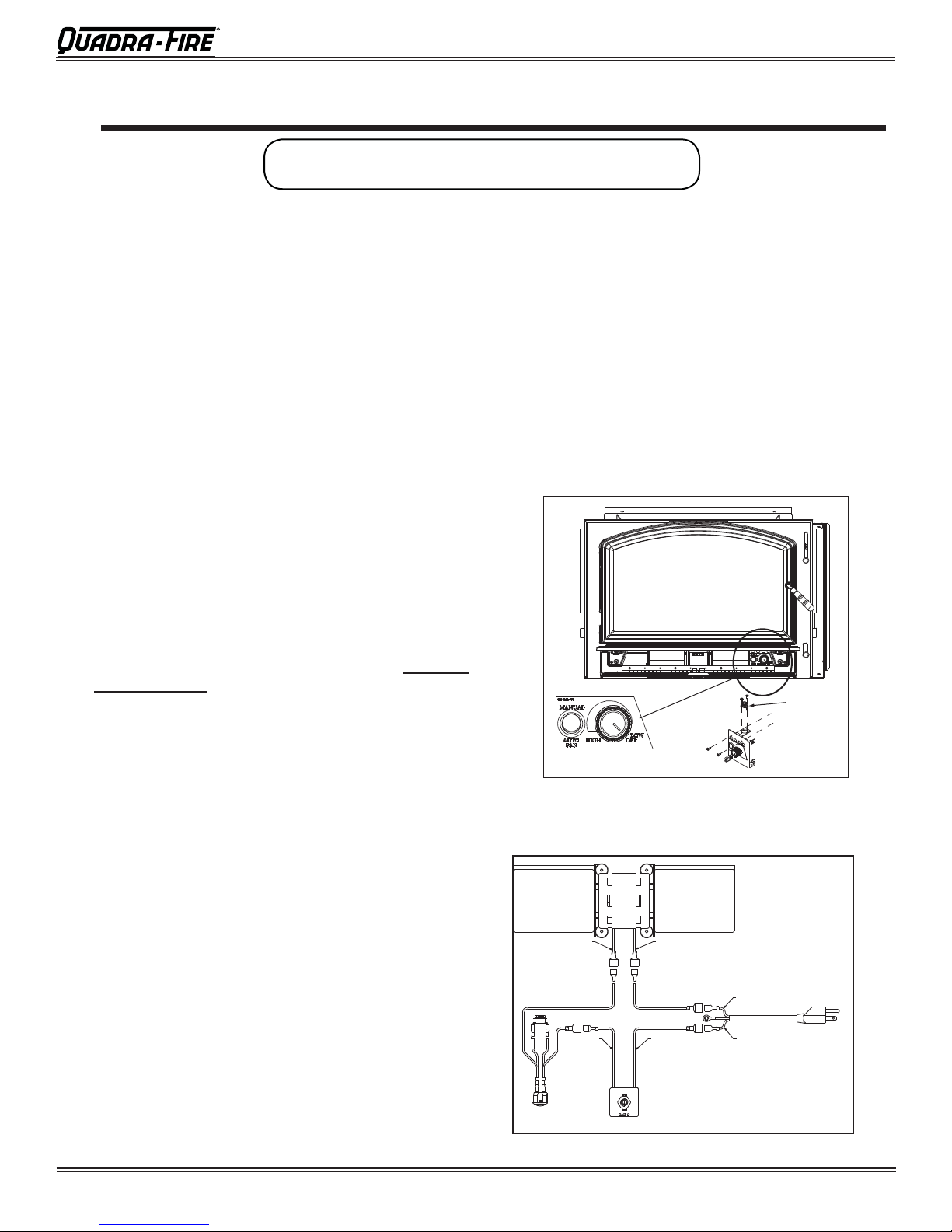
E. Blower Control Box & Snap Disc
Operating Instructions
1. The blower will turn on/off automatically when set to
AUTO. Figure 6.1 on page 6.
2. When set to MANUAL, the fan will turn on/off only when
you turn it on or off. This setting over-rides the internal
snap disc.
3. Swing the grille downward to expose the blower controls.
Adjust the speed of the fan by turning the HIGH/LOW
knob to the desired setting.
F. Blower Operating Instructions
1. Initial (cold) startup: Open both controls fully by raising
the Burn Rate Air Control all the way up until it stops and
PUSH the Start-up Air Control back until it stops.
blower tends to cool the appliance. Leave the blower off
until the burn is well established, i.e., 30 minutes.
2. High Burn Setting: Both controls are open. Burn Rate
Air Control is pulled up and the Start-up Air Control is fully
pushed in. Blower may remain on.
3. Medium-High Burn Setting*: Burn Rate Air Control
is closed then opened to 1 inch to fully open (pull up).
Blower may remain on.
4. Medium-Low Burn Setting*: Burn Rate Air Control
is closed then opened to 1/4 inch to 1/2 inch (pull up).
Leave the blower off until the burn is well established, i.e.,
30 minutes.
5. Low Burn Setting*: Burn Rate Air Control is closed
(down position).
Leave the blower off until the burn is well
established, i.e., 30 minutes.
*NOTE: For burn settings 3 to 5 the Start-up Air Control
needs to be pushed in (Open) then pulled forward to activate the Automatic Combustion Control (ACC).
NOTE: For maximum effi ciency and lowest emissions,
when operating the blower in either the automatic or
manual setting for the low and medium low burn settings
leave the blower off until the burn is well established, i.e.,
30 minutes.
The
October 12, 2015
7075-205B
Page 5
Voyageur Grand
6. The blower is equipped with a rheostat (speed control).
The highest blower speed is obtained by turning the
rheostat on, then adjusting back towards “OFF” as far as
possible without turning the blower off. For a low blower
speed, turn the control knob clockwise as far as possible
Blower Controls Under Ash Lip
ANUAL: over-
ides the internal
nap disc
AUTO: Fan with turn ON/OFF
automatically and is controlled
by the internal Snap Disc
Figure 15.1
Figure 6.1
NOTICE!
Do NOT operate a circulating fan within close proximity, approximately 4 ft (1.2m), of appliance
• Can reverse air fl ow, blowing hot air into appliance
cavity.
• Can damage appliance blower due to overheating.
Page 6
7075-205B
October 12, 2015

2
Maitenance & Service
2
A. Disposal of Ashes
• Frequency: When ash reaches the top of the brick
covers (should not spill over covers). Leave 1/4 inch
(6mm) of ash in the bottom of the firebox.
• By: Homeowner
WARNING! Risk of Fire! Ashes could contain hot embers.
• Place ashes in a metal container with a tight-fi tting lid.
• The closed container should be placed on a noncombustible
fl oor or on the ground, well away from all combustible
materials, pending fi nal disposal.
• If the ashes are disposed of by burial in soil or otherwise
locally dispersed, they should be retained in the closed
container until all cinders have thoroughly cooled
Voyageur Grand
Creosote - Formation and Need for Removal
• When wood is burned slowly, it produces tar and other
organic vapors, which combine with expelled moisture
to form creosote.
• The creosote vapors condense in the relatively cool
chimney fl ue of a slow-burning fi re.
• As a result, creosote residue accumulates on the fl ue
lining. When ignited this creosote makes an extremely
hot fi re.
• The chimney and chimney connector shall be inspected
every two months during the heating season to
determine when a creosote buildup has occurred.
•
When creosote has accumulated it shall be removed to
reduce the risk of a chimney fi re.
B. Chimney and Chimney Connector
Inspection/Cleaning
• Frequency: Every 2 months during heating season or
as recommended by a certifi ed chimney sweep; more
frequently if chimney exceeds or is under 14-16 feet (4.3
to 4.8m) measured from bottom of appliance.
• By: Certifi ed chimney sweep
• Remove all ash from the fi rebox and extinguish all hot
embers before disposal.
• Allow the appliance to cool completely.
•
If your type of installation involves a full reline of the
chimney, it will be necessary to either remove the baffl e
from the insert, or remove the insert from the fi replace
and disconnect the vent prior to cleaning the chimney.
Refer to page 23 in this manual for instructions on Baffl e
Removal.
• If your type of installation is direct connect within a masonry
chimney, the insert will need to be pulled out from the
fi replace and disconnected from the fl ue prior to cleaning
the chimney.
• The creosote or soot should be removed with a brush
specifi cally designed for the type of chimney in use.
• Clean out fallen ashes from the fi rebox.
• It is also recommended that before each heating season
the entire system be professionally inspected, cleaned
and repaired if necessary.
WARNING! Risk of Fire!
Do not use chimney cleaners or fl ame colorants in your
appliance. It will corrode your pipe.
C. Appliance Inspection - Routine
• Frequency: Every 2 months at the same time the
chimney and chimney connector are inspected.
• By: Homeowner
Check for:
• Cracks in glass
• Door handle - smooth cam operation
• Baffl e and ceramic blanket correct placement
• Baffl e for warpage
• Firebrick for cracks, broken or crumbly
• Door gasket. (Dollar bill test). Place a dollar bill between the stove and the door and then shut the door. If
you can pull the dollar bill out, replace the door gasket.
• Glass frame for loose screws
D. Cleaning Plated Surfaces
• Frequency: As desired
• By: Homeowner
• Clean all the fi ngerprints and oils from plated surfaces
BEFORE fi ring the appliance for the fi rst time.
• If not cleaned properly before lighting your fi rst fi re, the
oils can cause permanent markings on the plating.
• After the plating is cured, the oils will not affect the fi nish
and little maintenance is required.
• Wipe clean as needed.
CAUTION! Do not use polishes with abrasives. It will
scratch plated surfaces.
October 12, 2015
7075-205B
Page 7
Voyageur Grand
E. Glass Cleaning
• Frequency: As desired
• By: Homeowner
• Clean glass with a non-abrasive glass cleaner . Abrasive
cleaners may scratch and cause glass to crack.
• If the deposits on the glass are not very heavy, normal
glass cleaners work well. Heavier deposits may be
removed by using a damp cloth dipped in wood ashes or
by using a commercially available oven cleaner.
• After using an oven cleaner, it is advisable to remove any
residue with a glass cleaner or soap and water. Oven
cleaner left on during the next fi ring can permanently stain
the glass and damage the fi nish on plated metal surfaces.
• A portion of the combustion air entering the fi rebox is de-
fl ected down over the inside of the door glass.
• This air fl ow “washes” the glass, helping to keep smoke
from adhering to its surface.
• When operated at a low burn rate, less air will be fl owing
over the glass and the smoky, relatively cool condition of
a low fi re will cause the glass to become coated.
• Operating the appliance with the Burn Rate Air Control
and Start-Up Air Control all the way open for 15-20 minutes should remove the built up coating.
CAUTION! Handle glass assembly with care. Glass is
breakable.
• Avoid striking, scratching or slamming glass
• Avoid abrasive cleaners
• Do not clean glass while it is hot
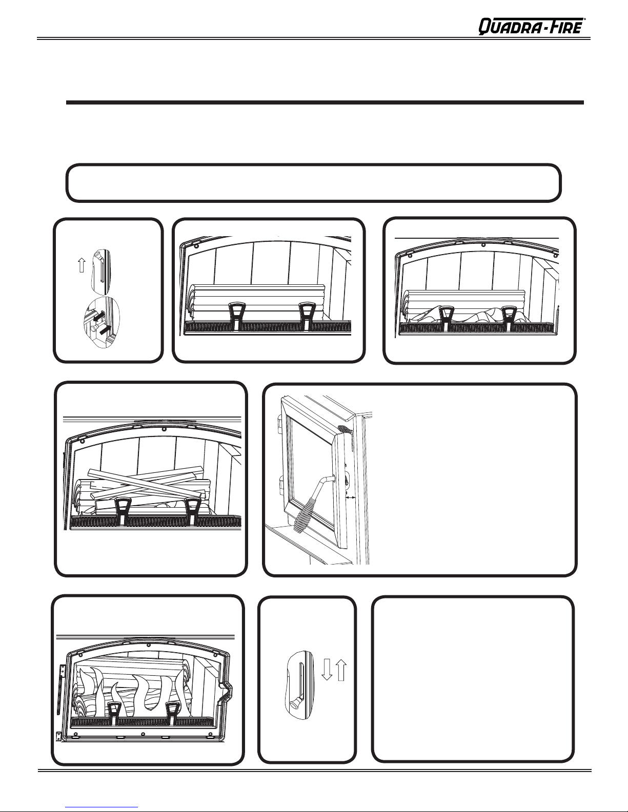
F. Inspect Firebrick & Replacement
Instructions
• Frequency: After each ash removal
• By: Homeowner
Replace the fi rebrick if they become crumbly and/or if
there is a 1/4 inch (6.35mm) gap between the bricks.
The fi rebox is lined with fi rebrick, which has exceptional
insulating properties. Do not use a grate; simply build
a fi re on the fi rebox fl oor. Do not operate appliance
without fi rebrick.
1. After the coals have completely cooled, remove all
old brick and ash from unit and vacuum fi rebox.
2. Remove new brick set from box and lay out to the
diagram shown in the instructions that come with
the replacement brick set.
3. Lay bottom bricks in unit.
4.
Install rear bricks on the top of the bottom bricks.
5. Install side bricks. Slide top of brick under clips
on side of fi rebox and push the bottom of the brick
until it is fl ush with the side of the unit.
Use Part 832-0550 when ordering individual brick. Provide
brick dimension or copy the page in the service parts list, mark
the desired brick and take it to your authorized dealer.
Page 8
7075-205B
October 12, 2015
Voyageur Grand
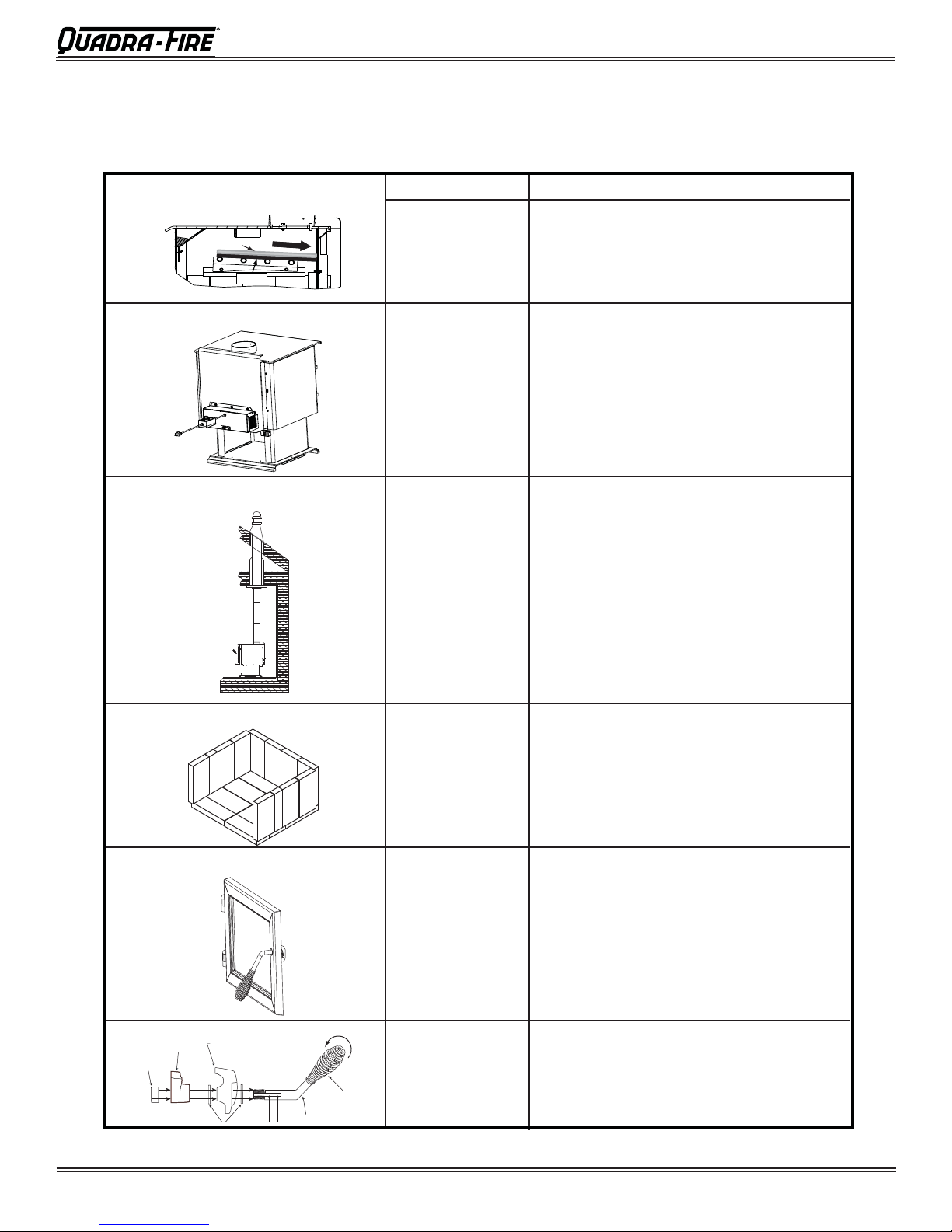
G. Quick Reference Maintenance Guide
CAUTION! Allow the appliance to completely cool
down before performing any cleaning or maintenance.
Baffl e & Blanket
Blanket
Baffle
Optional Blower
Chimney System
Frequency
MONTHLY
or
After Every
Cord of Wood
YEARLY
or
After Every
4 Cords of
Wood
EVERY 2
MONTHS
or
After Every
4 Cords of
Wood
Start the fi rst inspection after the fi rst 2 months of use,
or if performance changes, and adjust your schedule
accordingly . Maintenance is required for safe operation
and must be performed to maintain your warranty.
Task
Baffl e and blanket placement is critical to
heat output, effi ciency and overall life of the
unit. Make sure the baffl e is pushed all of the
way to the back of the fi rebox and the blanket
is laying fl at. Inspect baffl e for cracks.
Vacuum the blower impellers.
T
he chimney and chimney cap must be inspected for soot and creosote every two
months during the burn season or more frequency if chimney exceeds or is under 14-16 ft
(4.3m-4.8m) measured from bottom of appliance.
This will prevent pipe blockage, poor draft,
and chimney fi res.
Always burn dry wood to help prevent cap
blockage and creosote build-up.
Firebrick & Ash Removal
Door & Glass Assemblies
WEEKLY
or
After Every
25 Loads of
Wood
WEEKLY
or
After Every
25 Loads of
Wood
Ashes must be cool before you can dispose
of the ashes in a non-combustible container.
Firebrick is designed to protect your fi rebox.
After ashes are removed, inspect the fi re-
brick and replace fi rebricks that are crum-
bling, cracked or broken.
Keep door and glass gasket in good shape to
maintain good burn times on a low burn setting.
To test: place a dollar bill between the stove
and door and then shut the door. If you can
pull the dollar out, remove one washer from
door handle behind latch cam and try again. If
you can still pull it out, replace the door gasket.
Check the glass frame for loose screws to
prevent air leakage. Check glass for cracks.
Locknut
Door Handle
Latch Cam
Door Cross Section
(example)
Door Handle
Spring
Handle
WEEKLY
or
After Every 25
Loads of Wood
Check the door latch for proper adjustment.
This is very important especially after the door
rope has formed to the stove face.
Check door handle for smooth cam operation.
Note: These are generic drawings and may not represent your specifi c model.
October 12, 2015
7075-205B
Page 9
Voyageur Grand
H. Troubleshooting Guide
With proper installation, operation, and maintenance your woodstove will provide years of trouble-free service. If you do
experience a problem, this troubleshooting guide will assist you or a qualifi ed service person in the diagnosis of a problem
and the corrective action to be taken.
Start Fire Problems Possible Cause Solution
Can not get fi re started
Excessive smoke or spillage
Burns too slowly
Not enough heat output
Not enough kindling/paper or no
kindling/paper
Not enough air for fi re to ignite
Use dry kindling, more paper. Arrange kindling &
wood for air movement.
Check for restricted termination cap
Check for blockage of outside air kit (if installed).
Check for fl ue blockage.
Pre-warm fl ue before starting fi re (refer to Building
a Fire Section).
Check for adequate vent height (refer to Chimney
Height Section).
Open window below the appliance towards the
wind.
Fire burns too fast
Wood condition is too wet, too
large
Bed of coals not established
before adding wood
Flue blockage such as birds’
nests or leaves in termination
cap
Down draft or negative pressure
Competition with exhaust
devices
Extremely dry or soft wood
Overdrafting
Use dry, seasoned wood (refer to Seasoned Wood
Section).
Start with paper & kindling to establish bed of
coals (refer to Building a Fire Section).
Have chimney inspected for creosote and cleaned
by a certifi ed chimney sweep.
Do not use exhaust fans during start-up (refer to
Negative Pressure Section).
Open window below the appliance towards the
wind.
Mix in hardwood.
Mix in less seasoned wood after fi re is established
(refer to Wood Fuel Section).
Check for correct vent height; too much vertical
height creates overdrafting.
Check location of vent termination (refer to
Chimney Termination Requirement Section).
Page 10
7075-205B
October 12, 2015
3
Service Parts Replacement
3
UNPLUG APPLICE FROM ANY POWER SOURCE
BEFORE REPLACING ANY COMPONENTS
A. Glass Replacement
(Replace with 5mm ceramic glass only)
1. Ensure that the fi re is out and the appliance is cool to
the touch.
2. Protect a table or c ounter top with padding or towels.
Protect your hands and wear gloves to prevent injury.
3. Remove the door with the broken glass by lifting t he
door up and off of the hinges.
4.
Lay door face down on a table or co unter making sure
the handle hangs over the edge so the door lays fl at, on
a soft surface.
5. Remove the screws from each glass retainer and remove
the glass. (If screws are diffi cult to remove, soak with
penetrating oil fi rs t).
6. Center the glass with edges evenly overlapping the
opening in the door, (i.e. same space top and bottom,
left and right sides).
7. Replace the glass retainer s. Be careful not to cross
thread the screws.
8. Tighten each retainer just a few turns until each is
secured. Check again for centering of glass in door
frame. Continue to tighten each retainer alternately, a
few turns at a time, until the glass is secure. DO NOT
OVERTIGHTEN - can cause glass to break.
9. Replace the door on the appliance.
Voyageur Grand
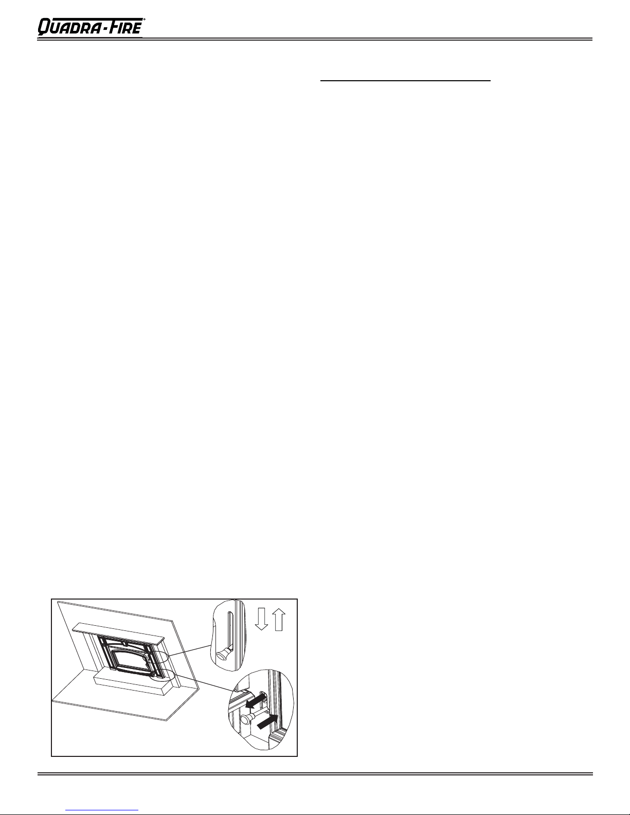
B. Snap Disc Replacement (Cont’d)
2. Remove the 2 screws from the blower access assembly
and slide assembly away from the appliance
3
. Locate the snap disc bracket assembly behind the blower
controls on the right side under the ash lip. Figure 8.1
4. Remove the 2 mounting screws in the blower control
bracket and slide assembly towards you.
5. Using a Phillips head screw driver, remove the 2 screws
from the snap disc and lift the snap disc off of the mounting
bracket. Disconect the wires and replace with new snap
disc and re-connect the wires.
6. Slide the blower control bracket back into position and
secure with the 2 mounting screws.
Blower Controls & Snap
Disc Under Ash Lip
Snap Disc
WARNING! Risk of Fire or Injury!
Use only glass that is specifi ed in the manual, DO NOT
replace with any other material. Glass breakage will occur.
CAUTION!
Handle glass with care.
• Inspect the gasket to ensure it is undamaged.
• Do NOT strike, slam or scratch glass.
• Do NOT operate appliance with glass & door assembly
removed.
• Do NOT operate with glass cracked, broken or
scratched.
Quadra-Fire appliances are equipped with ceramic super
heat-resistant glass, which can only be broken by impact or
misuse.
B. Snap Disc Replacement
1. The grille on the blower access assembly is hinged. Swing
the grille downward to expose the 2 screws. Figure 9.1 on
page 9.
October 12, 2015
7075-205B
Figure 7.1 Snap Disc Location
C. Wiring Diagram
Blower
Black
Snap Disc
Black
Switch
Rheostat
White
White
White
Black
Power Cord
Page 11
Voyageur Grand
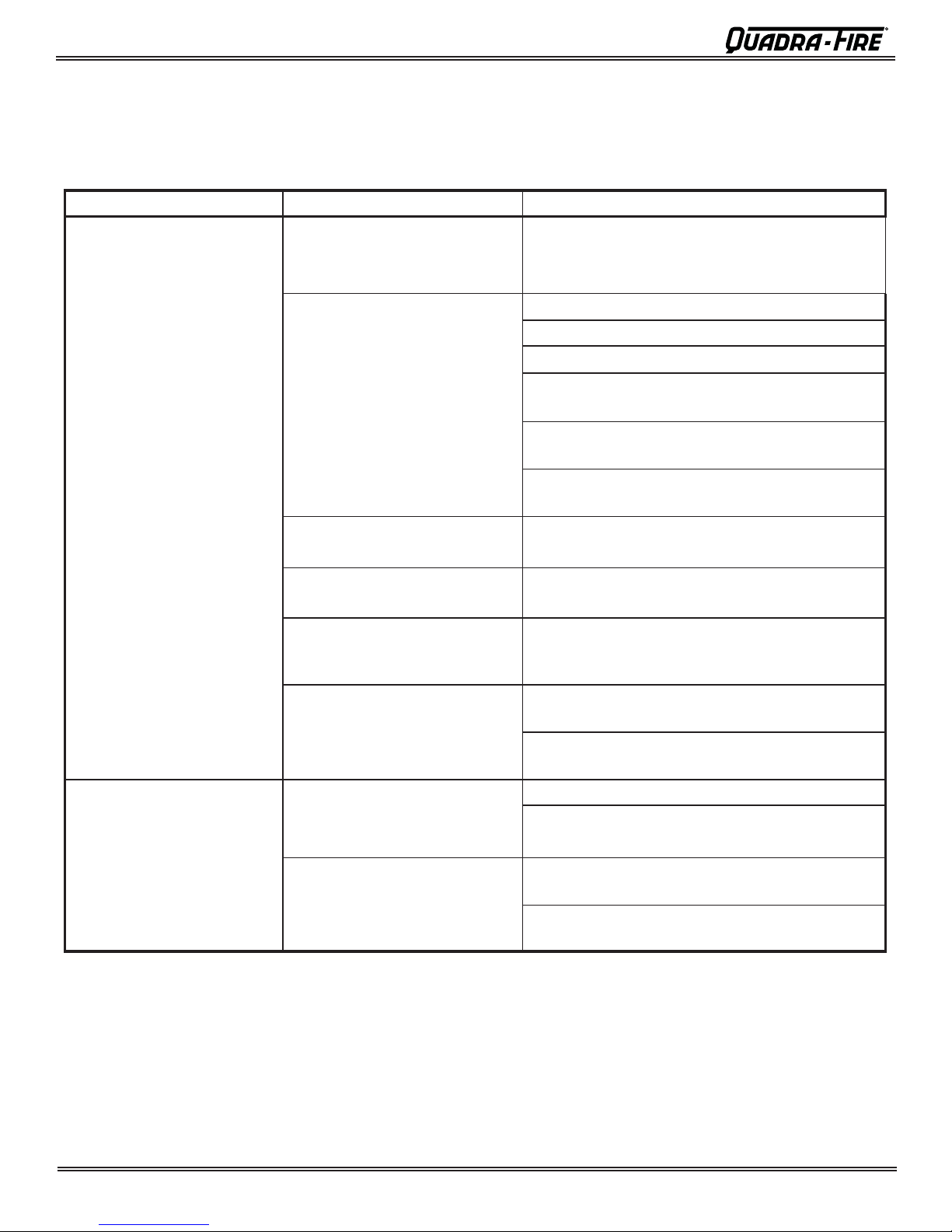
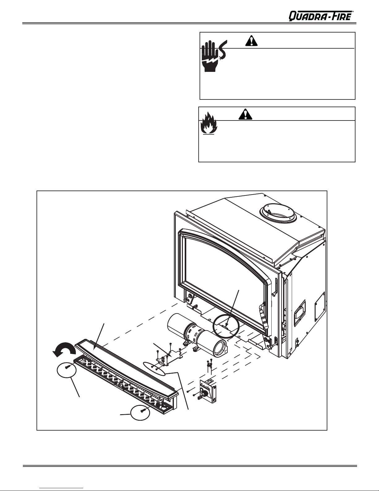
D. Blower Replacement
1. The grille on the blower access assembly is hinged.
Swing the grille downward to expose the 2 screws.
Figure 8.1
2. Remove the 2 screws from the blower access assembly
and slide assembly away from the appliance.
3. Disconnect the wires from the blower.
4. Remove the 2 screws from the hold down bracket and
pull the blower and bracket forward.
5. Remove the blower from the hold down bracket.
6. Remove the protection guards from each end of the
blower.
7. Re-install in reverse order. Be certain that the hold down
bracket’s screws are completely seated in the gromments. Insert the locating tab in the hold down bracket
into the placement slot.
CAUTION
Shock Risk
• Do NOT remove grounding prong from plug.
• Plug directly into properly grounded 3 prong
receptacle.
• Route cord away from appliance.
•
Do NOT route cord under or in front of appliance.
WARNING
Fire Risk
Do NOT allow hot coals or embers to overfl ow ash lip
• May melt protective wire coating on fan power
cord causing electrical short, fi re or injury
CAUTION! Unplug appliance
from power source before
replacing any components.
Blower Access
Assembly
Grille hinges
downward
Hold Down
Bracket
Placement Slot
Remove Screws &
Pull Access Assembly
away from Insert
Figure 8.1
Page 12
Remove Screws from Hold
Down Bracket and Pull
Forward
7075-205B
October 12, 2015
 Loading...