

Quadra-Fire GB40I, GRAND BAY 40 Installation & Operating Instructions Manual
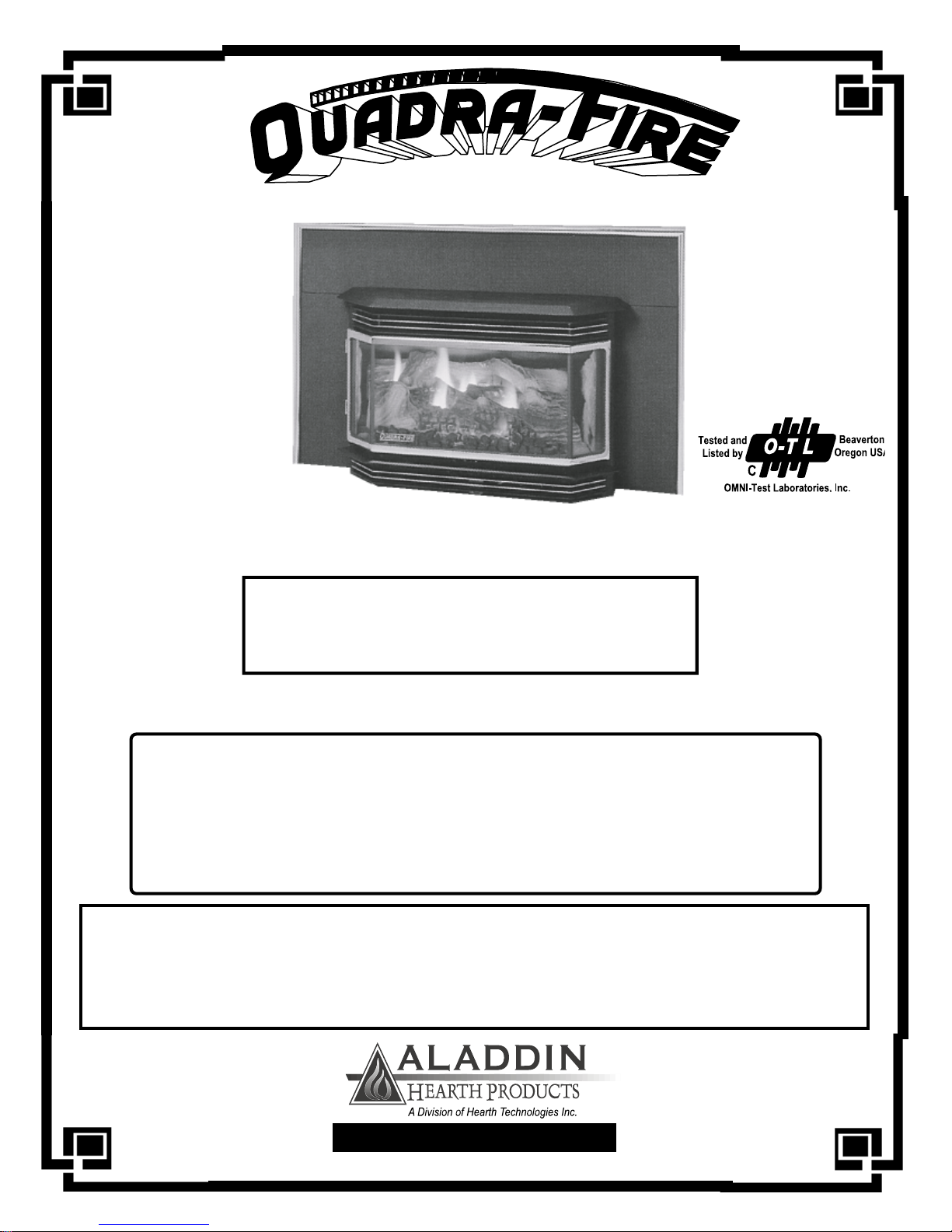
CONGRATULATIONS!
You are now the proud
owner of one of the finest
gas inserts on the market -
the QUADRA-FIRE
GB40I
INSTALLATION, OPERA TION, VENTING AND MAINTENANCE
North America’s Best
GRAND BAY 40 GAS INSERT
This Manual contains instructions for
WARNING
If the information in this manual is not followed exactly, a
fire or explosion may result causing property damage,
personal injury, or death.
FOR YOUR SAFETY:
• Extinguish any open flame.
• Open windows.
• Do not try to light any appliance.
• Do not touch any electric switch.
• Do not use any telephone in your building.
DO NOT store or use gasolive or other flammable vapors and
liquids in the vicinity of this or any other appliance.
WHAT TO DO IF YOU SMELL GAS
• Immediately call your gas supplier from a
neighbor’s phone.
• Follow the gas supplier’s instructions.
• If you cannot reach your gas supplier,
call the fire department.
WARNING
Improper installation, adjustment, alteration, service or maintenance can cause injury or
property damage. Refer to this manual for corr ect installation and operational procedur es. for
assistance or additional information consult a qualified installer, service agency, or the gas
supplier.
401 N. Wynne Street
Colville, WA 99114
SAVE THESE INSTRUCTIONS
(Revised March 2000) Part #250-2641 #842-1270
www.aladdinhearth.com
aladdin@aladdinhearth.com
GB 40 I - FIREPLACE INSERT
Welcome
Aladdin Hearth Products welcomes you to our tradition of excellence! In choosing a
Quadra-Fire appliance, you have our assurance of commitment to quality , durability,
and performance.
This commitment begins with our research of the market, including ‘Voice of the Cus-
tomer’ contacts, ensuring we make products that will satisfy your needs. Our Research
and Development facility then employs the world’s most advanced technology to
achieve the optim um operation of our stoves, inserts and fireplaces. And yet we are
old-fashioned when it comes to craftsmanship . During manufacturing each unit is
meticulously fabricated and gold surfaces are hand-finished for lasting beauty and
enjoyment. Our pledge to quality is completed as each model undergoes a quality
control inspection. Additionally, we feel it is important to offer you several finishing
options and accessories to compliment your home’s décor, individualize the use of
your appliance, and provide financial options in acquiring a quality hearth appliance.
Ask your Quadra-Fire Dealer f or inf ormation on these options. From design, to fabrication, to shipping: Our guar antee of quality is more than a word, it’s Quadra-Fire
tradition, and we proudly back this tradition with a Lifetime W arranty .
Prior to installation, we ask you to take a few moments to read this manual. It has
been our experience that your overall enjoyment of your new appliance will be greatly
enhanced by becoming familiar with its’ installation, operation and maintenance requirements. We wish you and y our family many years of enjoyment in the warmth and
comfort of your hearth appliance. Thank y ou f or choosing Quadra-Fire.
With warm regards,
President V .P. Research & Development
Controller Operations Manager V .P. Sales & Marketing
Western Sales Manager Central Sales Manager Eastern Sales Manager
Manufacturing Eng. Mgr. Sr . Purchasing Agent T echnical Support Manager
WELCOME
Customer Support Manager Human Resources Supervisor
Page 2
GB40-I with gold-plated H-channel door
March 2000
GB 40 I - FIREPLACE INSERT
NOTES
MODEL PURCHASED
SERIAL NUMBER
DATE PURCHASED
DEALERSHIP WHERE PURCHASED:
DEALER PHONE NUMBER
ADDITIONAL INFORMATION :
________________________________________________________________
________________________________________________________________
________________________________________________________________
________________________________________________________________
________________________________________________________________
________________________________________________________________
________________________________________________________________
________________________________________________________________
GB40-I
NOTES
A TT ACH YOUR SALES RECEIPT AND WARRANTY STUB HERE:
March 2000
Page 3

GB 40 I - FIREPLACE INSERT
T ABLE OF CONTENTS
Welcome ................................................................................................................................................... 2
Notes......................................................................................................................................................... 3
Safety Label.............................................................................................................................................. 5
Safety Notices .......................................................................................................................................... 6
Specifications ............................................................................................................................................ 7
Gas Line Connection................................................................................................................................. 7
Pressure Testing ....................................................................................................................................... 7
Safety Listings .......................................................................................................................................... 7
Dimensions................................................................................................................................................ 8
Minimum Fireplace Clearances ................................................................................................................ 9
Clearances to Combustibles...................................................................................................................... 10
High Altitude Operation ............................................................................................................................ 11
Installation
Panel & T rim Installation..................................................................................................................... 12
Brick Installation.................................................................................................................................. 13
Log Set Installation .............................................................................................................................. 14
Door Installation ................................................................................................................................... 15
Thermostat Installation ........................................................................................................................ 16
Blower Power Cord ......................................................................................................... ................... 17
Gas Connections.................................................................................................................................. 18
Vent Attachment to Flue Collar ........................................................................................................... 19
Flue Clamp Instructions....................................................................................................................... 20
V enting Requirements
Terminations ....................................................................................................................................... 21
Exhaust Spillage and Testing Procedure ............................................................................................ 23
Lighting Instructions.................................................................................................................................. 24
First Fire.................................................................................................................................................... 25
Maintenance
Cleaning and Inspection ...................................................................................................................... 26
Burner Tube Cleaning ......................................................................................................................... 26
Glass Cleaning ...................................................................................................................................... 26
Glass Replacement .............................................................................................................................. 27
Schematics................................................................................................................................................ 28
Blower & Snap Disc Replacement .......................................................................................................... 29
Conversion to Alternate Fuel .................................................................................................................... 30
Troubleshooting ......................................................................................................................................... 32
Zero Clearance Fireplace Kit ................................................................................................................... 33
Offset Adapter Kit .................................................................................................................................... 33
CONTENTS
Accessories & ServiceParts ..................................................................................................................... 34
Warranty ................................................................................................................................................... 35
Warranty Card Insert
Page 4
March 2000
GB 40 I - FIREPLACE INSERT
SAFETY LABEL
(As found on chain in lower front grill.)
MANUFACTURED BY:
GB40 -I NG
GB40-I LP
GAS-FIRED VENTED ROOM HEATER
SERIAL NO.
CAN 1-2.1-M86 / ANSI 21.11.1a-1993
Report #061-S-07-4
GB40-I (NG) GB40-I (NG) GB40-I (LP) GB40-I (LP)
For use with Natural Gas For use with Natural Gas For use with Propane For use with Propane
Altitude 0-2000' 2000-4500' 0-2000' 2000-4500'
Input High 46,000 BTUH 40,000 BTUH 40,000 BTUH 36,000 BTUH
Input Low 31,000 BTUH 29,000 BTUH 32,000 BTUH 25,000 BTUH
Output Blower off 33,600 BTUH 29,200 BTUH 30,000 BTUH 27,000 BTUH
Output Blower on 35,420 BTUH 31,000 BTUH 32,000 BTUH 28,440 BTUH
Manifold Pressure 3.5" WC 3.5" WC 10.0" WC 10.0" WC
Reduced Manifold Pressure 1.5" WC 1.5" WC 5.8" WC 5.8" WC
Min. Supply Pressure 4.5" WC 4.5" WC 11.0" WC 11.0" WC
Orifice Size (DMS)
Front burner #53 #54 #66 #67
Middle Burner #52 #53 #63 #64
Rear Burner #38 #37 #53 #54
401 N. Wynne
Colville, WA 99114
SAFETY LABEL
ATTENTION
This appliance must be installed in acordance with local codes, if any; if not,
follow current ANSI Z223.1/CAN 1-B149.
ELECTRICAL SUPPL Y: 120 V olts, 1.2 Amps, 60 Hz.
Install and use only in accordance with manufacturer’s installation and operating instructions.
For direct discharge without duct connections.
Not for use with solid fuel.
Keep burner and control compartment clean.
Due to high surface temperatures, keep children, clothing and furniture away.
MINIMUM CLEARANCES TO COMBUSTIBLES
SIDEWALL A 10" (255mm)
MANTEL C 12.5" (320mm)
MANTEL WIDTH G 1" (25mm)
NOTE: FOR EVERY 1" (25mm) OF MANTEL WIDTH ADD 1" (25mm)
TO CLEARANCE “C”. EX: MANTEL WIDTH 6" (150mm) -
CLEARANCE “C” MUST BE 17.5" (445mm)
NON-COMBUSTIBLE HEARTH EXTENSION
HEARTH HEIGHT (H) 0" (0mm) 2" (51mm) 4" (100mm)
HEARTH DEPTH (I) 24" (610mm) 22" (560mm) 0" (0mm)
HEARTH WIDTH J 30" (760mm)
DO NOT REMOVE THIS LABEL
MANUF ACTURED AS A:
GB40-I (NG)
GB40-I (LP)
FROM HEATER
March 2000
Page 5

GB 40 I - FIREPLACE INSERT
SAFETY NOTICES
This appliance should only be installed by a qualified installer . It is approved for installation in a bedroom.
Bedroom installation in Canada requires that the stove be connected to a thermostat. The appliance must
be electrically grounded in accordance with local codes, or the latest edition of the National Electric Code.
If no local codes exist, this appliance should be installed following the current codes:
CAN/CGA-B149.1 ........................................................................ Natural Gas Installation Code
CSA-C22.1 ....................................................................................Canadian Electrical Code
ANSI Z223.1 ................................................................................. National Fuel Gas Code
ANSI NFP A-70............................................................................. National Electrical Code
The control compartment, burner, and circulating air passageways MUST be kept clean and clear to allow
for adequate combustion and proper operation. Provide adequate clearances around air openings and adequate
accessibility clearance for service and operation. NEVER obstruct the openings of the appliance or the vent
termination on the exterior of the building. NEVER vent the appliance to other rooms or buildings; this
appliance must be vented ONLY to the outside, with a vertical termination. During installation, be sure to
maintain minimum clearances to combustibles, as shown on page 9. Always contact your local building
department or fire department prior to installing this appliance. If required, obtain a permit before installing,
and have the completed installation inspected. Failure to do this could jeopardize your homeowner’s insurance.
The area around the appliance MUST be kept free from combustible materials, gasoline and other
flammable vapors and liquids.
This appliance is hot during operation, and should be located out of heavy traffic areas and away from
furniture and draperies. Clothing or other flammable material should not be placed on or near the appliance.
Children and adults should be alerted to the hazards of high surface temperatures and should stay away to
avoid burns or clothing ignition. Children should not be left unsupervised in the room when this appliance is in
operation.
If any part of this appliance has been under water, DO NOT USE it!! Immediately call a qualified service
technician to inspect the appliance, and to replace any part of the control system or any gas control which
has been under water.
This appliance should NOT be modified under any circumstances. Any parts removed for servicing must be
replaced before operating this appliance. Installation and repair should only be done by a qualified service
technician. The appliance and its venting system should be inspected and cleaned annually by a qualified
service technician. More frequent cleaning may be necessary due to excess lint and dust from carpeting,
bedding material, etc. Be sure to turn off gas valve and pilot before cleaning this appliance.
Install at least one smoke detector on each floor of your home to ensure your safety . They should be located
away from the gas appliance and close to the sleeping areas. Follow the smoke detector manufacturer’s
placement and installation instructions, and be sure to maintain regularly. Your local fire department may
provide assistance in selecting smoke detectors, or contact the Consumer Product Safety Commission,
W ashington, D.C. 20207.
SAFETY NOTICES
Warning: Do not operate appliance with the glass front removed, cracked or broken.
Replacement of the glass should be done by a licensed or qualified service person.
Page 6
March 2000
GB 40 I - FIREPLACE INSERT
SPECIFICATIONS
Manifold pressure 3.5” WC 10.0” WC
Minimum inlet gas supply pressure 4.5” WC 11 0” WC
Maximum inlet gas supply pressure 7.0” WC 14.0” WC
BTU input rating (high) 46,000 40,000
BTU input rating (low) 31,000 32,000
Efficiency with blower (steady state) 77% 79%
Efficiency without blower (steady state) 73% 75%
A.F.U.E. 65% 66%
GAS LINE CONNECTION
Gas line connection can be made near the lower rear of the appliance (3/8” gas hookup). You must
supply a shutoff valve installed in a visible location within 3’ of the insert.
CAUTION
IN SOME AREAS, GAS LINE PRESSURE MAY BE MORE THAN 1/2 PSIG (14” WC). IF YOU
BELIEVE THAT THIS MIGHT BE THE CASE IN YOUR LOCALITY, CONTACT YOUR GAS
SUPPLIER OR LOCAL UTILITY COMPANY. LINE PRESSURE GREATER THAN 1/2 PSIG
WILL DAMAGE THE APPLIANCE VALVE. YOU MUST INSTALL A REGULATOR UPSTREAM
FROM THE APPLIANCE IF LINE PRESSURE IS GREATER THAN 1/2 PSIG.
SPECIFICATIONS
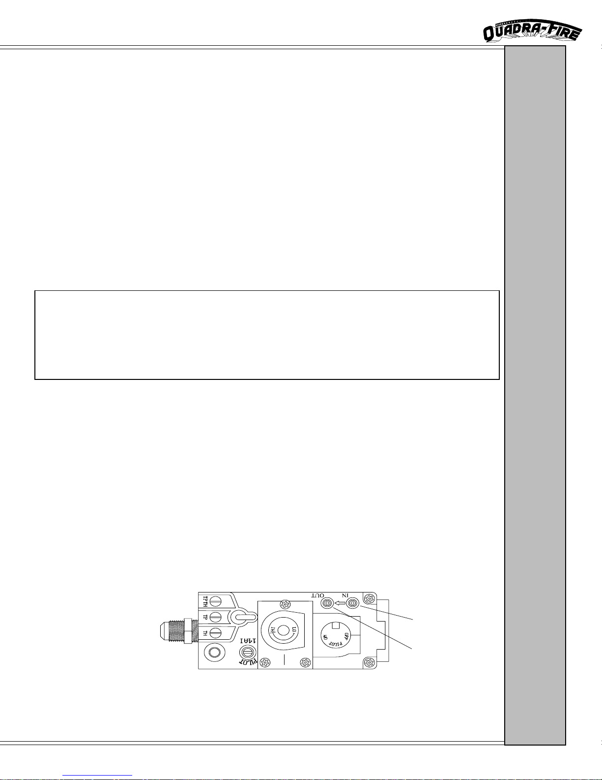
PRESSURE TESTING
During any pressure testing of the gas supply piping system that exceeds test pressures of 1/2 PSIG, this
appliance and its individual shutoff valve must be disconnected from the piping system. If test pressure is
less than or equal to 1/2 PSIG, then this appliance must be isolated from the piping system by closing its
individual shutoff valve. The gas valve is supplied with pressure test ports for checking input and output
pressures. These are located just below the on/off knob and can be found inside the hinged lower access
grill. The port on the left is for output pressure and the port on the right for input. Pressure can be
checked by turning the captured screw counterclockwise two or three turns and then placing the
manometer tubing over the test port. BE SURE TO CLOSE CAPTURED SCREWS AFTER TESTING
BY TURNING THEM CLOCKWISE. DO NOT OVERTIGHTEN SCREWS.
NOTE: To make flame and heat output adjustments, turn the HI-LO knob located on the center of the
valve (as seen below). Turn clockwise for a higher flame and counterclockwise for a lower flame
INPUT SIDE
TEST VALVE
OUTPUT SIDE
TEST VALVE
.
The Quadra-Fire GB40-I is listed to ANSI Z21.11.1 and CAN1-2.1 by OMNI-Test Laboratories, Inc.
March 2000
LISTINGS
Page 7
20 1/4” (514mm)
GB 40 I - FIREPLACE INSERT
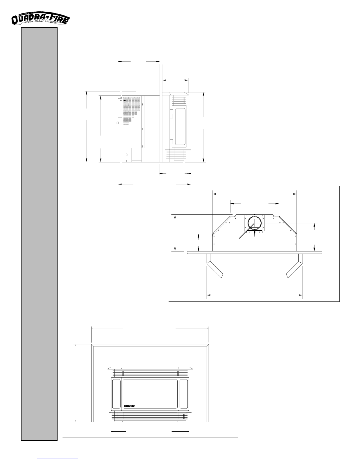
DIMENSIONS
11 7/8”
(302mm)
7 1/2”
(190mm)
20” (507mm)
19 1/8”
(485mm)
9”
(229mm)
21” (533mm)
26 1/4” (668mm)
15 1/4”
(387mm)
11 3/8”
42 1/2” (1080mm)
(289mm)
5 3/8” (136mm)
4” flue
29 7/8” (758m)
8/3/4”
(223mm)
DIMENSIONS
28 1/4”
(718mm)
Page 8
28 1/4” (718mm)
March 2000
GB 40 I - FIREPLACE INSERT
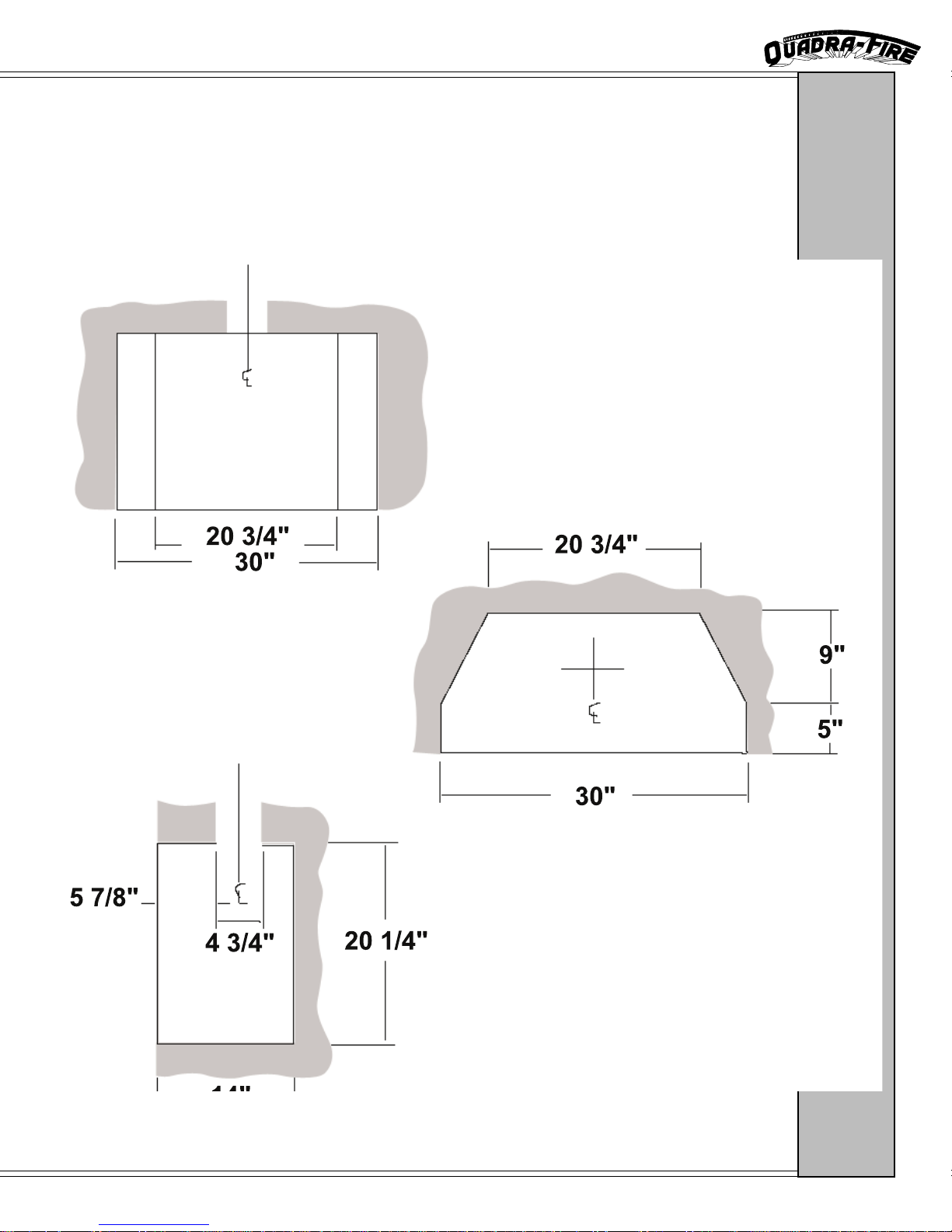
MINIMUM FIREPLACE CLEARANCES
The following diagrams show the minimum fireplace dimensions that are required for installation of the
Quadra-Fire GB40-I gas fireplace insert.
CLEARANCES
March 2000
Page 9
GB 40 I - FIREPLACE INSERT
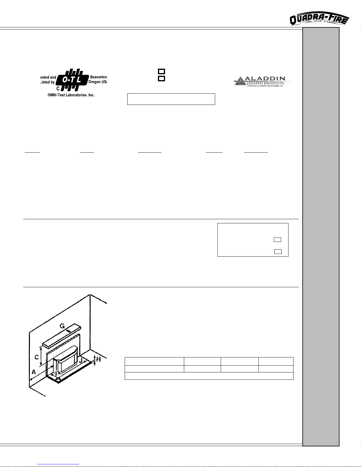
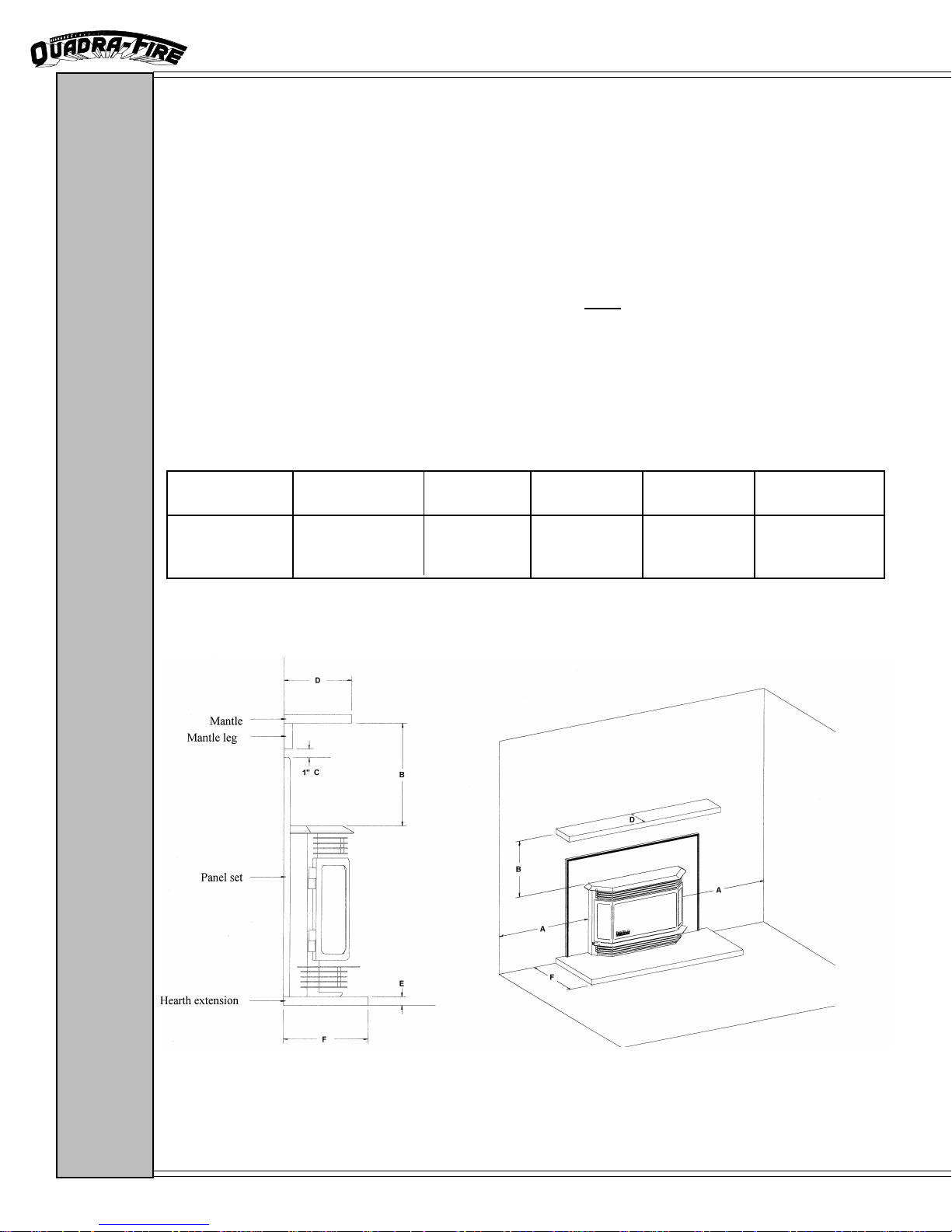
CLEARANCES TO COMBUSTIBLES
Minimum clearances to combustible materials
From HEATER TO: SIDEWALL A 10” (255mm)
From HEATER TO: MANTEL B 12.5” (320mm) *
From PANEL TOP TO: MANTEL LEG C 1” (25mm)
MANTEL WIDTH D 1” (25mm)
* NOTE: For every 1” (25mm) of MANTEL WIDTH, ADD 1” (25mm) to Clearance “C”.
Example: Mantel Width is 6” (150mm) - Clearance “C” must be 17.5” (445mm).
HEAR TH REQUIREMENTS: A minimum 3/8” (10mm) non-combustible material is required under
the appliance. The depth of the hearth extension is variable depending on the height of the non-combustible
hearth material. Follow the hearth extension clearance requirements noted below for compliance to this
requirement:
Height (E) 3/8”(10mm) 1” (25mm) 2” (51mm) 3” (76mm) 4” (102mm)
Depth (F) 24” 23” 22” 15” 0”
(610mm) (585mm) (560mm) (380mm) (0mm)
CLEARANCES
Page 10
March 2000
GB 40 I - FIREPLACE INSERT
HIGH ALTITUDE OPERATION
For installations in the United States and at altitudes above 2000 feet, the appliance input shall be adjusted
in accordance with local codes or, in the absence of any, follow the current ANSI Z223.1, National Fuel
Gas Code. For installation in Canada for altitudes up to 4500 feet, for altitudes above 4500 feet, contact
the authority having jurisdiction, or the manufacturer . Follow local codes or CAN 1 B-149.
NOTE: In the United States, input ratings of this unit are based on sea level operation, and shall not be
changed for operation at elevations up to 2000 feet (600m). For operation at elevations above
2000 feet, this appliance shall be reduced at the rate of 4% for each 1000 feet above sea level.
Exception: As permitted by the authority having jurisdiction.
EQUIVALENT ORIFICE SIZES A T HIGH AL TITUDES
(INCLUDES 4% INPUT REDUCTION FOR EACH 1000 FEET)
Orifice at sea level 2000 3000 4000 5000 6000 7000 8000 9000 10000
Natural Gas
Front 53 54 54 54 54 54 54 55 55 55
Middle 52 52 53 53 53 53 53 54 54 54
Rear 38 39 40 41 41 42 42 43 43 44
Propane
Front 66 67 67 68 68 68 69 69 69 70
Middle 63 64 64 65 65 65 66 66 67 68
Rear 53 54 54 54 54 54 54 55 55 55
HIGH ALTITUDE
March 2000
Page 11
 Loading...