

Quadra-Fire GRAND BAY 40, GB40FS Installation, Operation, Venting And Maintenance Instructions
Page 1
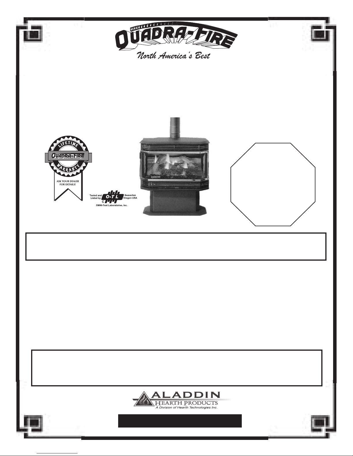
GRAND BAY 40 GAS FREESTANDING (GB40 FS)
INSTALLATION, OPERATION, VENTING
AND MAINTENANCE INSTRUCTIONS
CONGRATULATIONS!
You are now the proud owner of one of the nest gas
stoves on the market, the
QUADRA-FIRE
GB40FS
CAUTION!
PRIOR TO FIRST FIRE:
Clean gold door with a
glass cleanser and soft
cloth, as ngerprint oils
will cause discoloration on
gold when heated.
WARNING
If the information in this manual is not followed exactly, a re or explosion may result causing property
damage, personal injury, or death.
FOR YOUR SAFETY:
DO NOT store or use gasoline or other ammable vapors and liquids in the vicinity of this or any ther appliance.
WHAT TO DO IF YOU SMELL GAS
• Extinguish any open ame.
• Open windows.
• Do not try to light any appliance.
• Do not touch any electric switch.
• Do not use any telephone in your building.
• Immediately call your gas supplier from a neighbor’s
phone.
WARNING
Improper installation, adjustment, alteration, service or maintenance can cause injury or property damage. Refer
to this manual for correct installation and operational procedures. For assistance or additional information
consult a qualied installer, service agency, or the gas supplier.
• Follow the gas supplier’s instructions.
• If you cannot reach your gas supplier, call the re
department.
• Installation and service must be performed by a
qualied installer, service agency, or the gas
supplier.
401 N. Wynne Street
Colville, WA 99114
SAVE THESE INSTRUCTIONS
Part #250-2970 #842-1620
(Revised 01/2000)
www.aladdinhearth.com
Page 2
Grand Bay 40 Gas Freestanding
Aladdin Hearth Products welcomes you to our tradition of excellence! In choosing a Quadra-Fire
appliance, you have our assurance of commitment to quality, durability, and performance.
This commitment begins with our research of the market, including ‘Voice of the Customer’ contacts,
ensuring we make products that will satisfy your needs. Our Research and Development facility then
employs the world’s most advanced technology to achieve the optimum operation of our stoves, inserts
and replaces. And yet we are old-fashioned when it comes to craftsmanship. During manufacturing
each unit is meticulously fabricated and gold surfaces are hand-nished for lasting beauty and enjoyment.
Our pledge to quality is completed as each model undergoes a quality control inspection. Additionally,
we feel it is important to offer you several nishing options and accessories to compliment your home’s
décor, individualize the use of your appliance, and provide nancial options in acquiring a quality hearth
appliance. Ask your Quadra-Fire Dealer for information on these options. From design, to fabrication,
to shipping: Our guarantee of quality is more than a word, it’s Quadra-Fire tradition, and we proudly
back this tradition with a Lifetime Warranty.
Prior to installation, we ask you to take a few moments to read this manual. It has been our
experience that your overall enjoyment of your new appliance will be greatly enhanced by becoming
familiar with its’ installation, operation and maintenance requirements. We wish you and your family
many years of enjoyment in the warmth and comfor t of your hearth appliance. Thank you for
choosing Quadra-Fire.
With warm regards,
President V.P. R & D
Controller Operations Manager V.P. Sales & Marketing
W E L C O M E
Western Sales Manager Central Sales Manager Eastern Sales Manager
Manufacturing Eng. Mgr. Sr. Purchasing Agent Technical Support Manager
Customer Support Manager Personnel & Safety Manager
Page 2
January 2000 January 2000
Page 3
N O T E S
Grand Bay 40 Gas Freestanding
MODEL PURCHASED:
SERIAL NUMBER:
DATE PURCHASED:
DEALERSHIP WHERE PURCHASED:
DEALER PHONE NUMBER
ADDITIONAL INFORMATION :
________________________________________________________________
________________________________________________________________
________________________________________________________________
_________________________________________________________________
_________________________________________________________________
_________________________________________________________________
_________________________________________________________________
_________________________________________________________________
GB40FS
N O T E S
ATTACH YOUR SALES RECEIPT AND WARRANTY STUB HERE:
Page 3
Page 4

C O N T E N T S
Grand Bay 40 Gas Freestanding
TABLE OF CONTENTS
Welcome.............................................................................. 2
Notes ................................................................................... 3
Safety Label......................................................................... 5
Safety Notices ..................................................................... 6
Specications ...................................................................... 7
Gas Line Connection........................................................... 7
Pressure Testing .................................................................. 7
Listings ................................................................................ 7
Dimensions.......................................................................... 8
Installation
Clearances to Combustibles................................................... 9
Hearth Requirements ............................................................. 9
High Altitude Operation .......................................................... 10
Unpacking the Stove............................................................... 11
Gas Valve Location................................................................. 11
Door Operation....................................................................... 12
Brick Installation ..................................................................... 14
Log Set Installation................................................................. 16
Thermostat Installation ........................................................... 18
Fan Power Cord...................................................................... 18
Remote Control & Wall Switch................................................ 18
Installation Procedure
Gas Connections.................................................................... 19
Venting Requirements
Terminations ........................................................................... 20
Vent Attachment to Flue collar................................................ 21
Exhaust Spillage and Testing Procedure ................................ 22
Lighting Instructions ............................................................... 23
First Fire ................................................................................. 24
Operation Controls ................................................................. 24
Maintenance
Cleaning and Inspection......................................................... 25
Burner Tube Cleaning ............................................................. 25
Glass Cleaning ....................................................................... 25
Glass Replacement ................................................................ 26
Schematics............................................................................. 27
Blower Replacement .............................................................. 28
Troubleshooting ...................................................................... 29
Conversion to Alternate Fuel.................................................. 30
Accessories & Replacement Parts ......................................... 34
Warranty................................................................................. 35
Warranty Card ........................................................................ Insert
Page 4
January 2000 January 2000
Page 5
Grand Bay 40 Gas Freestanding
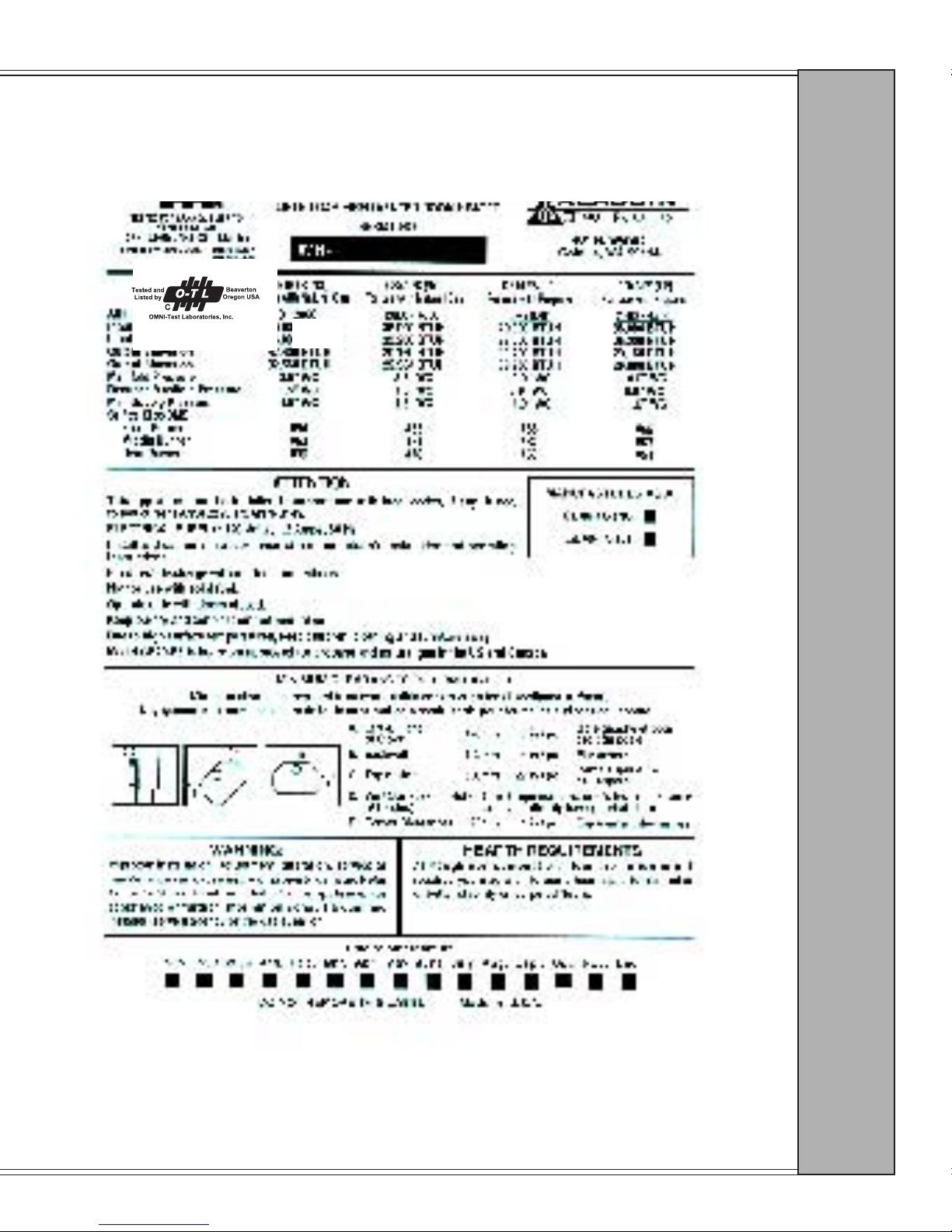
GB40FS SAFETY LABEL
(FOUND ON BACK OF STOVE)
S A F E T Y L A B E L
Page 5
Page 6

Grand Bay 40 Gas Freestanding
SAFETY NOTICES
This appliance should only be installed by a qualied installer. It is approved for installation in a bedroom.
Bedroom installation in Canada requires that the stove be connected to a thermostat. The appliance must be
electrically grounded in accordance with local codes, or the latest edition of the National Electric Code. If
no local codes exist, this appliance should be installed following the current codes:
CAN/CGA-B149.1 ........................................................................ Natural Gas Installation Code
CSA-C22.1..................................................................................... Canadian Electrical Code
ANSI Z223.1.................................................................................. National Fuel Gas Code
ANSI NFPA-70.............................................................................. National Electrical Code
The control compartment, burner, and circulating air passageways MUST be kept clean and clear to allow
for adequate combustion and proper operation. Provide adequate clearances around air openings and
adequate accessibility clearance for service and operation. NEVER obstruct the openings of the appliance
or the vent termination on the exterior of the building. NEVER vent the appliance to other rooms or
buildings; this appliance must be vented ONLY to the outside. During installation, be sure to maintain
minimum clearances to combustibles, as shown on page 9. Always contact your local building
department or re department prior to installing this appliance. If required, obtain a permit before
installing, and have the completed installation inspected. Failure to do this could jeopardize your
homeowner’s insurance.
The area around the appliance MUST be kept free from combustible materials, gasoline and other
ammable vapors and liquids.
This appliance is hot during operation, and should be located out of heavy trafc areas and away from
furniture and draperies. Clothing or other ammable material should not be placed on or near the
appliance. Children and adults should be alerted to the hazards of high surface temperatures and should
stay away to avoid burns or clothing ignition. Children should not be left unsupervised in the room
when this appliance is in operation.
If any part of this appliance has been exposed to water, DO NOT USE it!! Immediately call a qualied
service technician to inspect the appliance, and to replace any part of the control system or any gas
control which has been under water.
This appliance should NOT be modied under any circumstances. Any parts removed for servicing must
be replaced before operating this appliance. Installation and repair should only be done by a qualied service
technician. The appliance and its venting system should be inspected and cleaned annually by a qualied
service technician. More frequent cleaning may be necessary due to excess lint and dust from carpeting,
bedding material, etc. Be sure to turn off gas valve and pilot before cleaning this appliance.
Install at least one smoke detector on each oor of your home to ensure your safety. They should be located
away from the gas appliance and close to the sleeping areas. Follow the smoke detector manufacturer’s
placement and installation instructions, and be sure to maintain regularly. Your local re department may
provide assistance in selecting smoke detectors, or contact the Consumer Product Safety Commission,
Washington, D.C. 20207.
WARNING: Do not operate appliance with the glass front removed, cracked or broken. Replacement of
the glass should be done by a licensed or qualied service person.
Page 6
January 2000 January 2000
Page 7
Grand Bay 40 Gas Freestanding
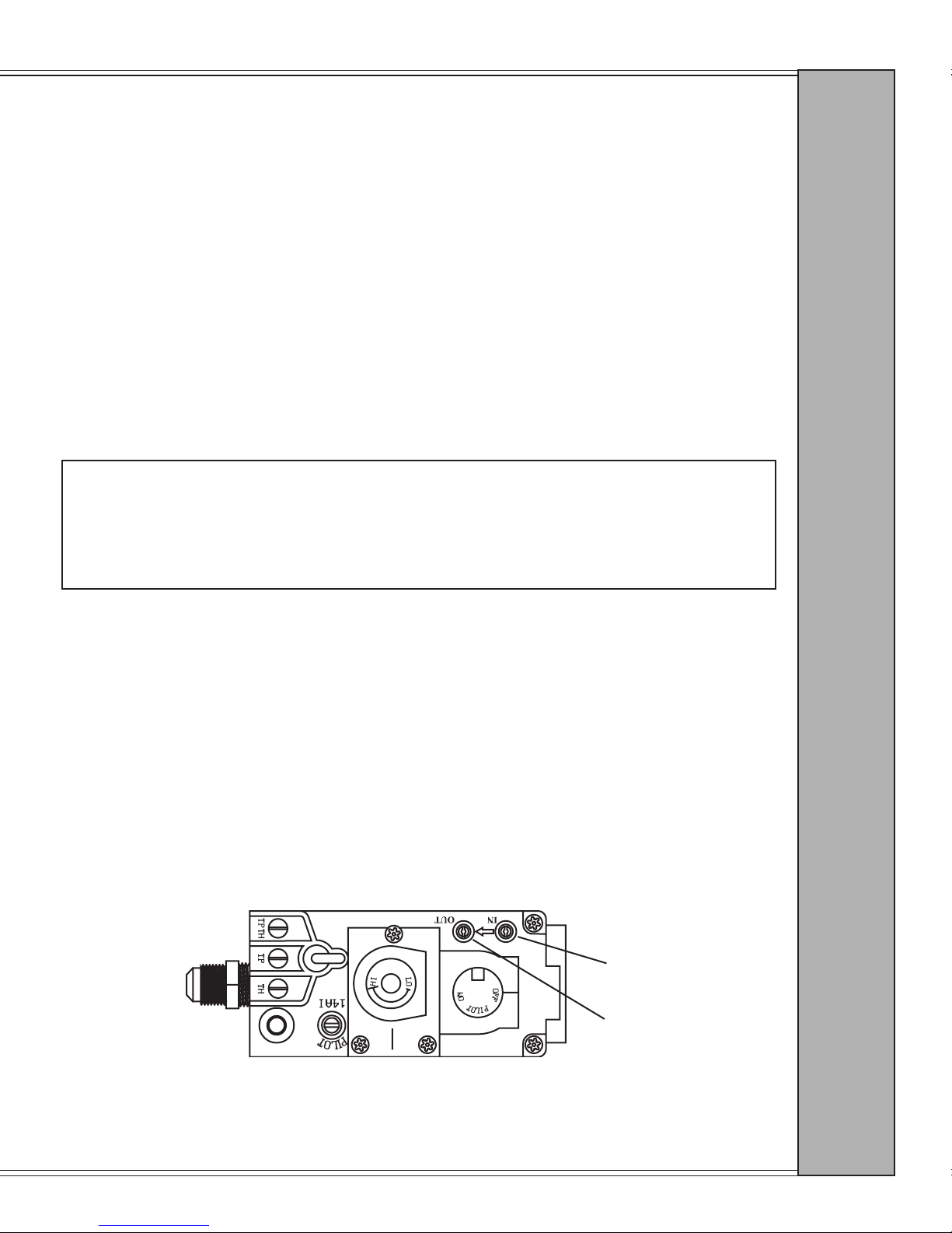
OUTPUT SIDE
TEST VALVE
INPUT SIDE
TEST VALVE
SPECIFICATIONS
NATURAL GAS PROPANE
Manifold pressure 3.5” WC 10.0” WC
Minimum inlet gas supply pressure 4.5” WC 11 0” WC
Maximum inlet gas supply pressure 7.0” WC 14.0” WC
BTU input rating (high) 40,000 40,000
BTU input rating (low) 28,000 28,000
Efciency with fan (steady state) 81.4% 83%
Efciency without fan (steady state) 81% 81%
A.F.U.E. 66% 68%
GAS LINE CONNECTION
Gas line connection can be made near the lower rear of the appliance (3/8” gas hookup). You must supply
a shutoff valve installed in a visible location within three feet (3’) of the stove.
CAUTION
In some areas, gas line pressure may be more than 1/2 psig (14” wc). If you believe that this might
be the case in your locality, contact your gas supplier or local utility company. Line pressure
greater than 1/2 psig will damage the appliance valve. You must install a regulator upstream from the
appliance if line pressure is greater than 1/2 psig.
S P E C I F I C A T I O N S
PRESSURE TESTING
During any pressure testing of the gas supply piping system that exceeds test pressures of 1/2 PSIG, this
appliance and its individual shutoff valve must be disconnected from the piping system. If test pressure is
less than or equal to 1/2 PSIG, then this appliance must be isolated from the piping system by closing its
individual shutoff valve. The gas valve is supplied with pressure test ports for checking input and output
pressures. These are located just next to the on/off knob and can be found inside the hinged lower access
grill. The port on the left is for output pressure and the port on the right for input. Pressure can be checked
by turning the captured screw counterclockwise two or three turns and then placing the manometer tubing
over the test port. BE SURE TO CLOSE CAPTURED SCREWS AFTER TESTING BY TURNING
THEM CLOCKWISE. DO NOT OVERTIGHTEN SCREWS.
NOTE: To make ame and heat output adjustments, turn the HI-LO knob located on the center of the valve
(as seen below). Turn clockwise for a higher ame and counterclockwise for a lower ame.
The Quadra-Fire GB40 FS is listed to ANSI Z21.11.1 and CAN 1-2.1 by OMNI-Test Laboratories, Inc.
LISTINGS
Page 7
Page 8
Grand Bay 40 Gas Freestanding
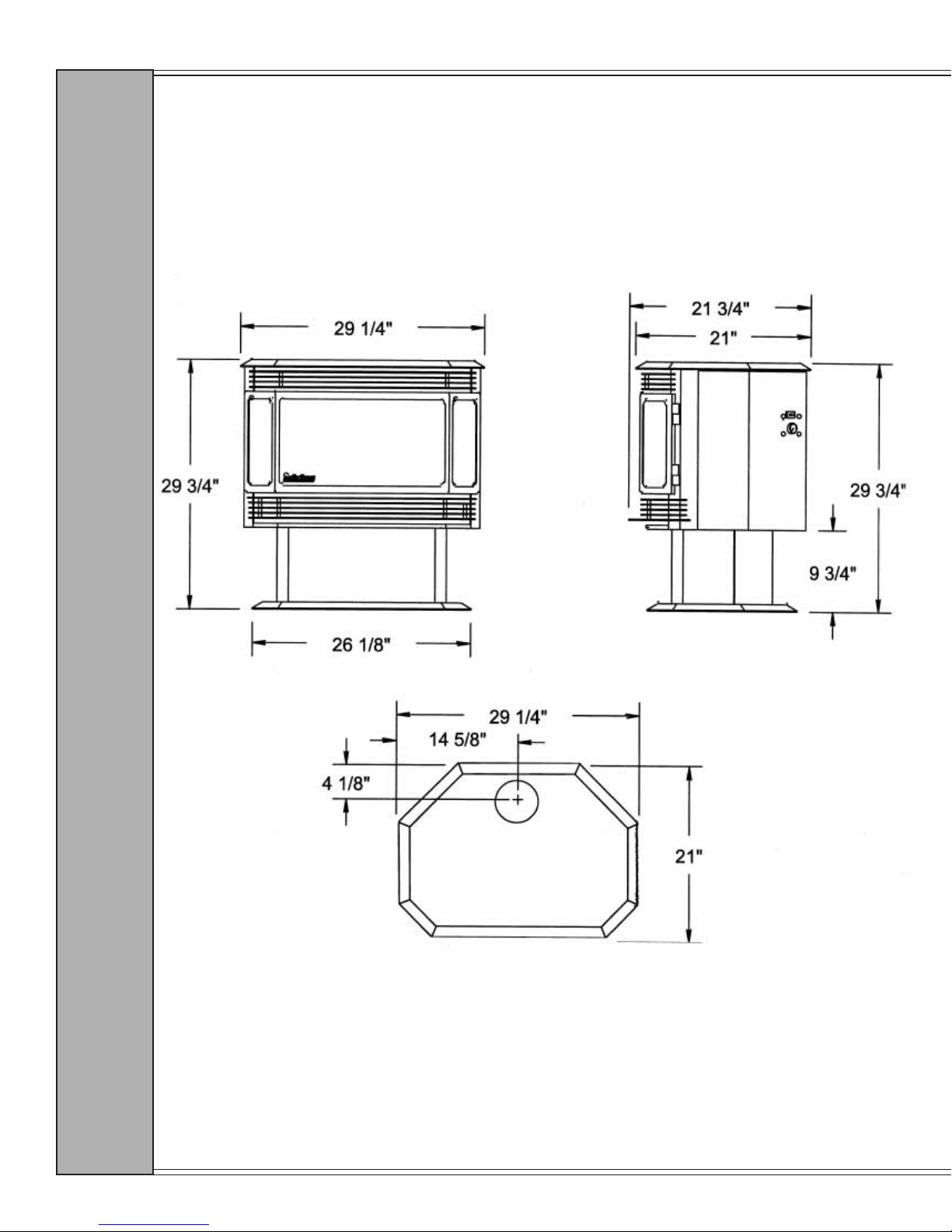
DIMENSIONS
D I M E N S I O N S
Page 8
January 2000 January 2000
Page 9
Grand Bay 40 Gas Freestanding
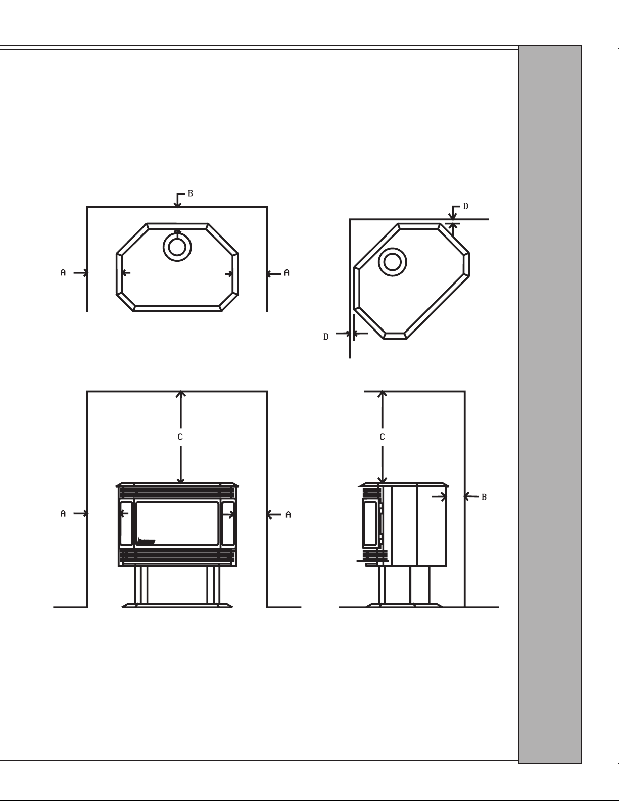
CLEARANCES TO COMBUSTIBLES
Minimum clearances to combustible materials from stove body:
A Side wall to combustible 7” (178mm)
B Back wall to combustible 4” (102mm)
C Top of unit 22” (560mm)
D Corner clearance 1” (25mm)
C L E A R A N C E S
HEARTH REQUIREMENTS
The oor area beneath the stove must be stable, level and strong enough to support the stove
without a tipping hazard. Wood ooring, ceramic tile, brick hearths, or high pressure laminate
ooring applied directly over the sub-ooring material meet this requirement. If the appliance
is installed over carpet or combustible tile (vinyl tile) , a metal or wood panel extending the full
width and depth of the appliance must be installed.
Page 9
Page 10
Grand Bay 40 Gas Freestanding
HIGH ALTITUDE OPERATION
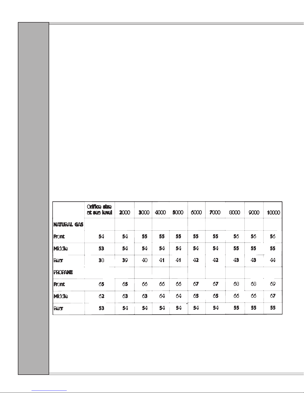
For installations in the United States and at altitudes above 2000 feet, the appliance input shall
be adjusted in accordance with local codes or, in the absence of any, follow the current ANSI
Z223.1, National Fuel Gas Code. For altitudes above 4500 feet, contact the authority having
jurisdiction, or the manufacturer.
NOTE: In the United States, input ratings of this unit are based on sea level operation, and
shall not be changed for operation at elevations up to 2000 feet (600m). For operation
at elevations above 2000 feet, this appliance shall be reduced at the rate of 4% for each
1000 feet above sea level.
Exception: As permitted by the authority having jurisdiction.
EQUIVALENT ORIFICE SIZES AT HIGH ALTITUDES
(INCLUDES 4% INPUT REDUCTION FOR EACH 1000 FEET)
H I G H A L T I T U D E
Page 10
January 2000 January 2000
Page 11

Grand Bay 40 Gas Freestanding
UNPACKING THE STOVE
1. Unbolt pallet from appliance using a 7/16” wrench to remove the two bolts from the
underside of the pallet.
2. Logs, twigs, brick refractory, glowing embers, touch-up paint, tee handle, and this owner’s
manual are shipped in the rebox for security in shipping.
3. Appliance door is sold and packaged in its own box.
GAS VALVE LOCATION
U N P A C K I N G S T O V E
1. To gain access to gas valve, cut wire ties (shown below).
2. Bottom grill hinges down; stove controls will then be visible.
3. See Operation Controls on page 22 for information on using the controls to operate the stove.
Page 11
Page 12
Grand Bay 40 Gas Freestanding
DOOR OPERATION INSTRUCTIONS
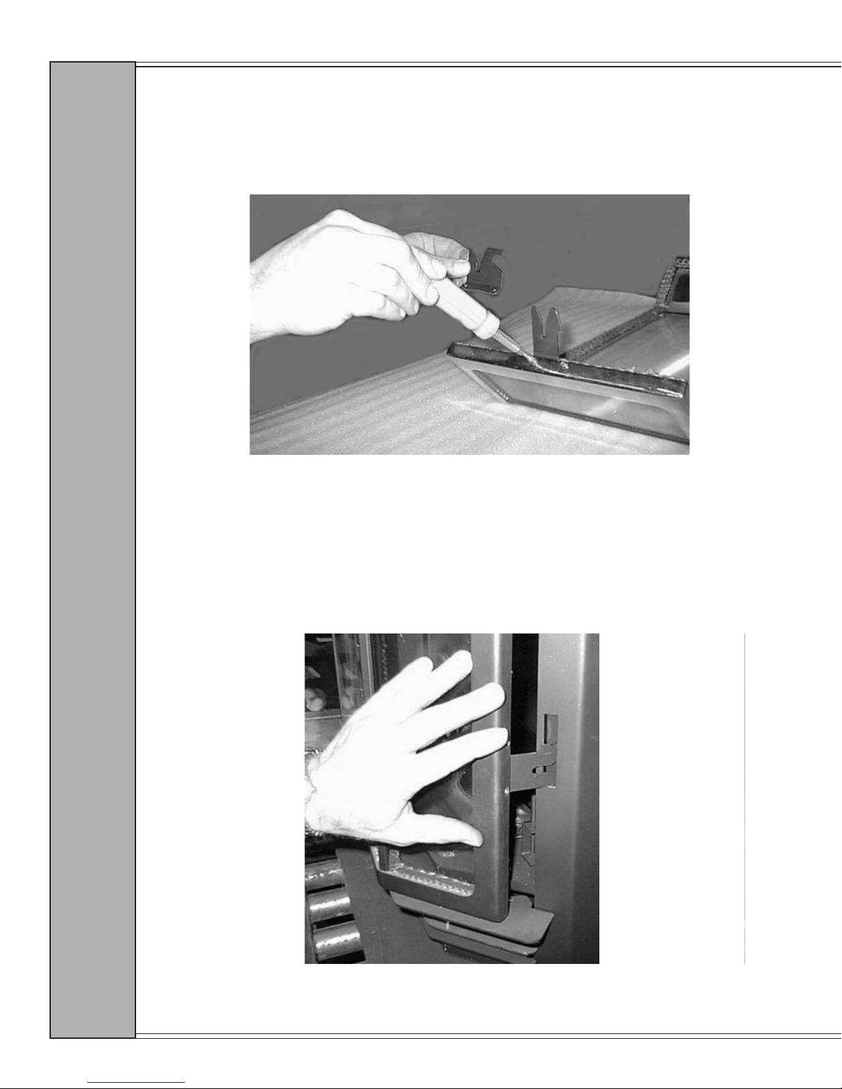
1. Verify that the proper door hook (part number 450-7490) is installed on the door. See Fig. A.
OLD
NEW
2. Install the door to check the latchbox adjustment. When closing the door, look between the door and
the face of the stove at the latching arm. See Fig. B. Watch to see that the door hook is lifting up the
latch, and when the door is fully closed that the latch returns to its original position. If the latch does
not return, the latchbox is adjusted too tightly.
FIG. A
D O O R O P E R A T I O N
Page 12
FIG. B
January 2000 January 2000
Page 13
Grand Bay 40 Gas Freestanding
DOOR OPERATION INSTRUCTIONS
3. Open the door and place a sheet of paper between the door and the stove to check for door rope
tension. Close the door and pull on the paper to feel the amount of pressure required to slide the paper
out. Repeat this process at both sides of the door and at the center of the top and bottom of the door. If
the paper does not have enough tension, the latchbox is adjusted too loosely.
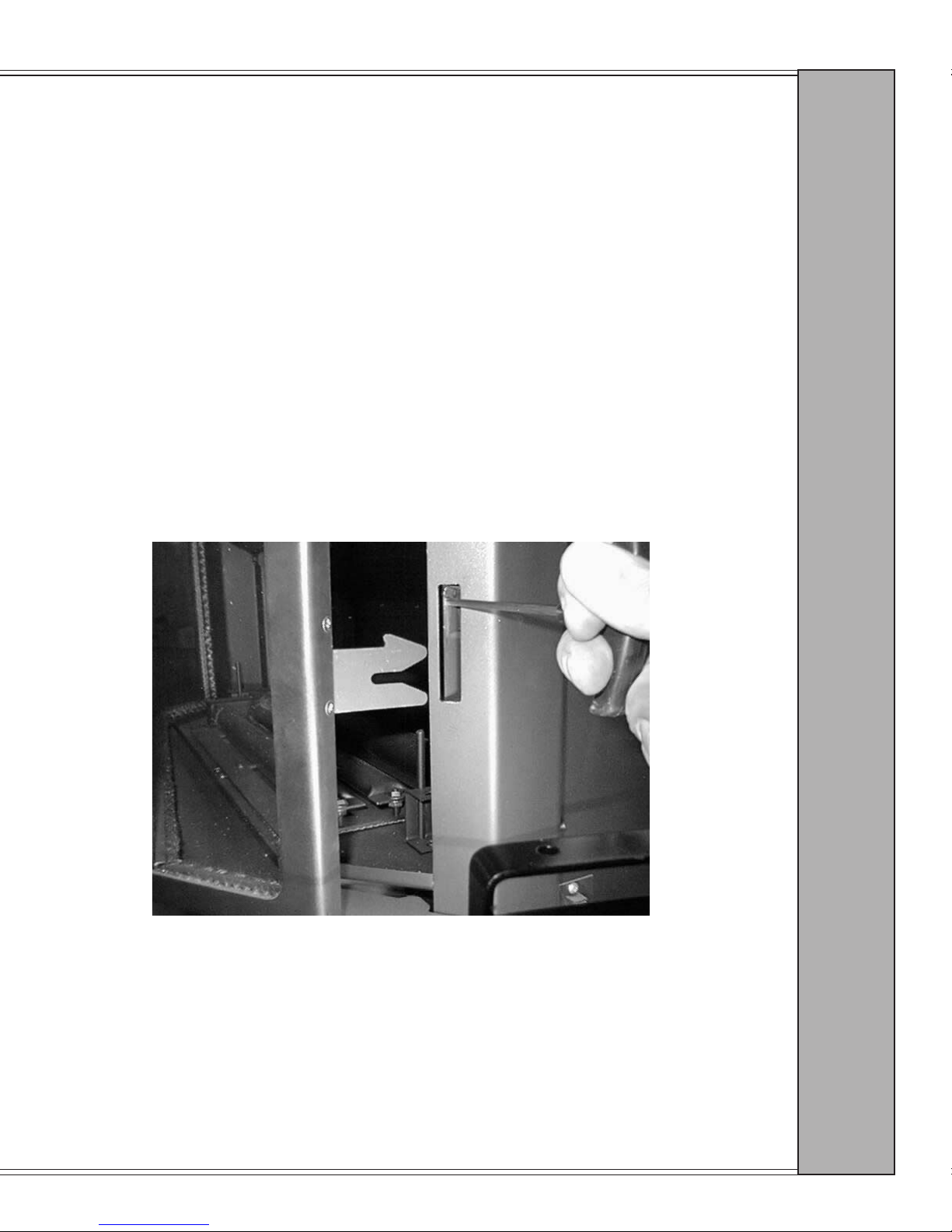
4. To adjust the latchbox, open the door using the “T” handle allen wrench to press the “nger” of latch
arm upward until door is released. See Fig. C. Using a 11/32" socket wrench (or 9mm) loosen the
four, 8-32 mounting nuts, slide the latchbox forward if it is too tight, or towards the back if it is too
loose, then secure with four, 8-32 nuts. Close the door and check for proper seal. Repeat process
until a proper seal is obtained. When adjustment is complete, close and latch the door. Pull out on the
door, to ensure the door is properly latched.
5. Repeat process until a proper seal is obtained.
D O O R O P E R A T I O N
FIG. C
Page 13
Page 14
Grand Bay 40 Gas Freestanding
BRICK INSTALLATION
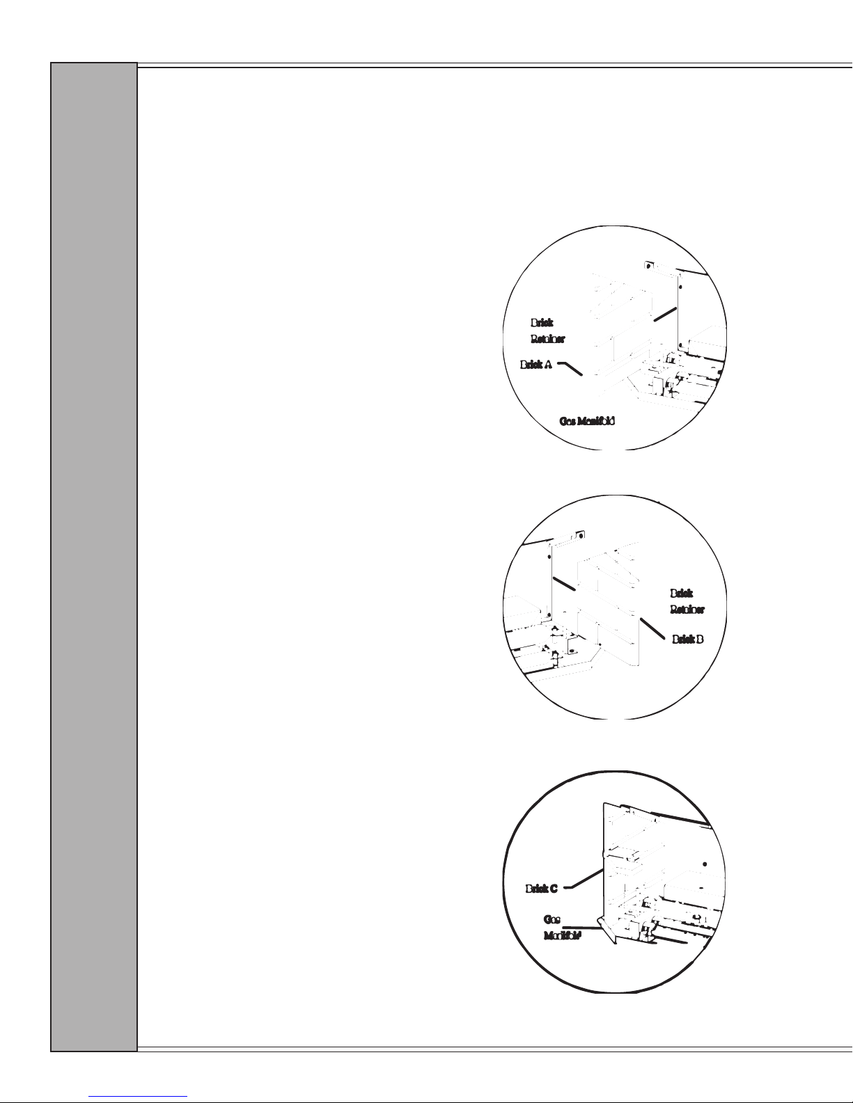
The brick in this unit is packed in the rebox to prevent breakage during shipping. To install
the brick, follow the directions below:
B R I C K
1. Open stove door.
2. Place brick A on the left side of the
rebox so that it slides into the slots
on the top of the rebox and behind
the manifold block.
3. Place brick B on the right side of
the rebox in the slot provided.
4. Place brick C on the left side of
the firebox floor in front of the
manifold block.
I N S T A L L A T I O N :
Page 14
January 2000 January 2000
Page 15
Grand Bay 40 Gas Freestanding
BRICK INSTALLATION
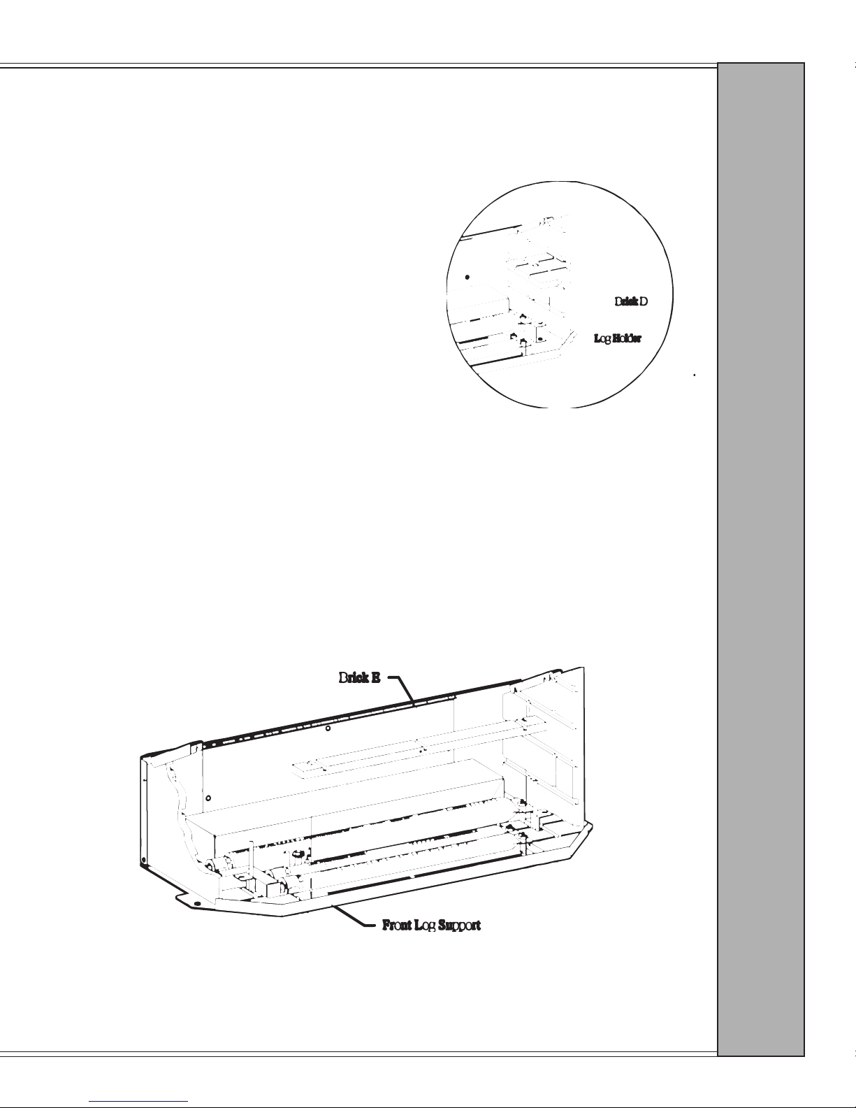
5. Place brick D on the right side of the rebox oor so
that the cutout slides around the log holder.
I N S T A L L A T I O N :
6. Slide brick E in front of the front burner tube so
that the brick ts between the burner tube and the
face of the insert. Brick must be moved toward face
of insert, and MUST NOT BLOCK front burner
tube air shutter.
B R I C K
Page 15
Page 16
Grand Bay 40 Gas Freestanding
INSTALLING THE LOG SET
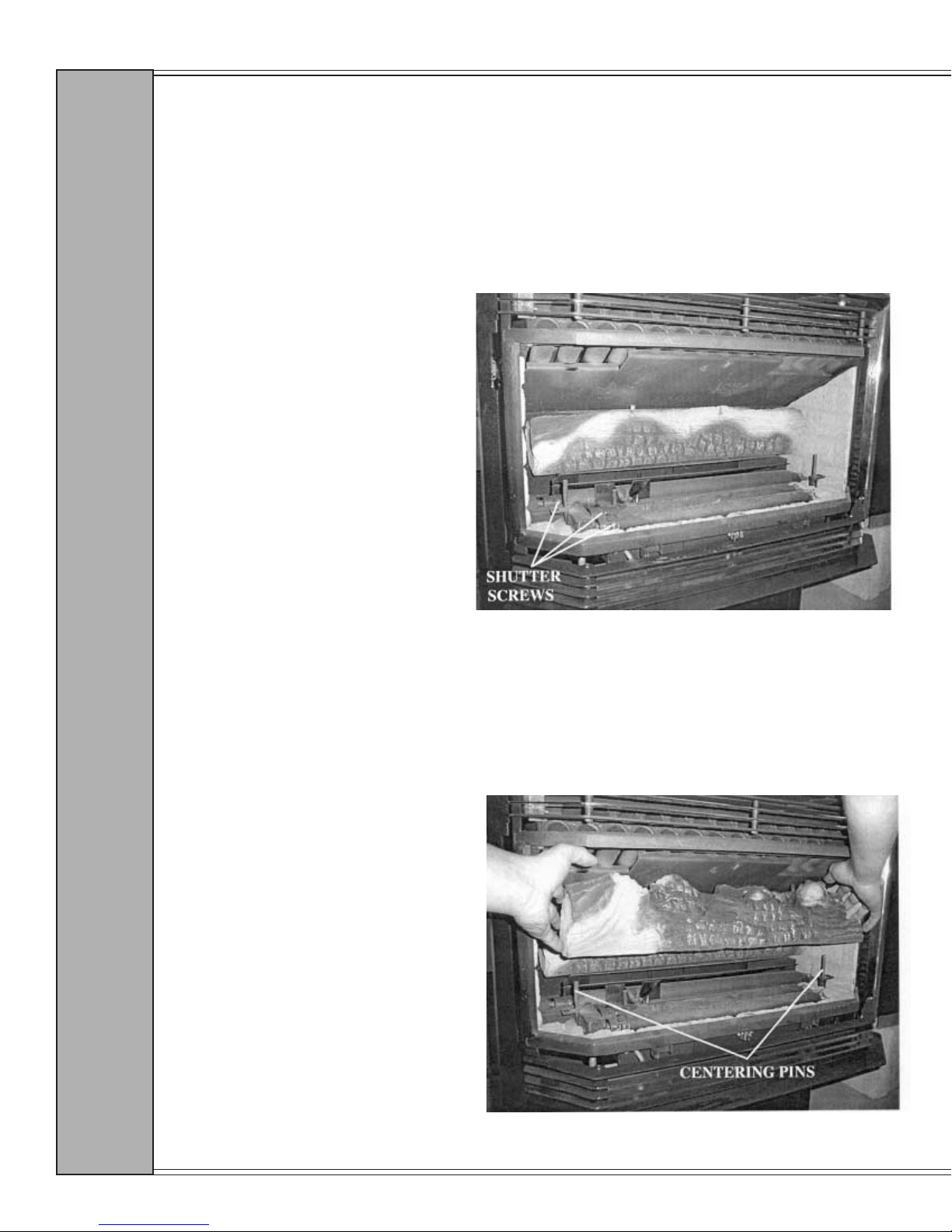
CORRECT LOG PLACEMENT IS IMPORTANT TO PREVENT SOOTING! The vacuumformed ceramic logs are extremely fragile. PLEASE HANDLE CAREFULLY. Small chips on
the logs can be covered up using the touch-up paint supplied with the stove.This appliance has
been supplied with external shutter adjustments. Loosen the 3 shutter locking screws at left side
of burners.
L O G S E T
1. Install rear log on log shelf
ensuring that both log shelf and
log are pressed rmly against
back wall.
2. Install front log by positioning
over centering pins and lowering. (Take care not to force and
cause damage to molded holes
in bottom of log.)
I N S T A L L A T I O N :
Page 16
January 2000 January 2000
Page 17
INSTALLING THE LOG SET
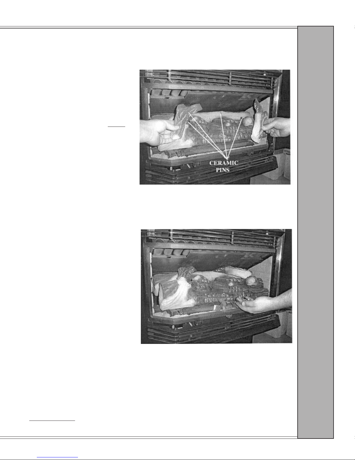
3. Place right twig on front and rear
log using ceramic pins and placement holes in bottom of twig for
alignment. (If ceramic pins are too
close, tilt front log forward, do not
make new holes in twigs.) Repeat
step for left twig.
Grand Bay 40 Gas Freestanding
I N S T A L L A T I O N :
4. Place ember nuggets across front of
burner.
5. Light appliance and let logs cure for 30 minutes. Adjust shutters to give good ame
characteristics.
NOTE: If ame tips have dark yellow or black tips, shutters need to be opened.
6. After correct ame adjustment has been achieved, cool appliance, remove twigs and front log
and tighten shutter adjustment screws.
IMPORTANT: If shutter adjustment screws are not tightened, expansion and contraction of
burner can allow shutter to close and cause sooting.
L O G S E T
Page 17
Page 18
Grand Bay 40 Gas Freestanding
THERMOSTAT INSTALLATION
If desired, a thermostat may be installed to regulate the Quadra-Fire GB40 FS. It is important to
use a thermostat designed for millivolt operation. Do not connect this appliance to a thermostat
serving any other appliance.
OPTIONAL THERMOSTATS
Manual Thermostat
Part #812-2880
Anticipator Setting 1.2
T H E R M O S T A T
Electronic Setback
Part #811-0520
RECOMMENDED MAXIMUM
LEAD LENGTH (TWO WIRE)
WHEN USING WALL THERMOSTAT/
SWITCH
Wire Size Maximum Length
16 gauge 65 feet
18 gauge 40 feet
20 gauge 25 feet
22 gauge 18 feet
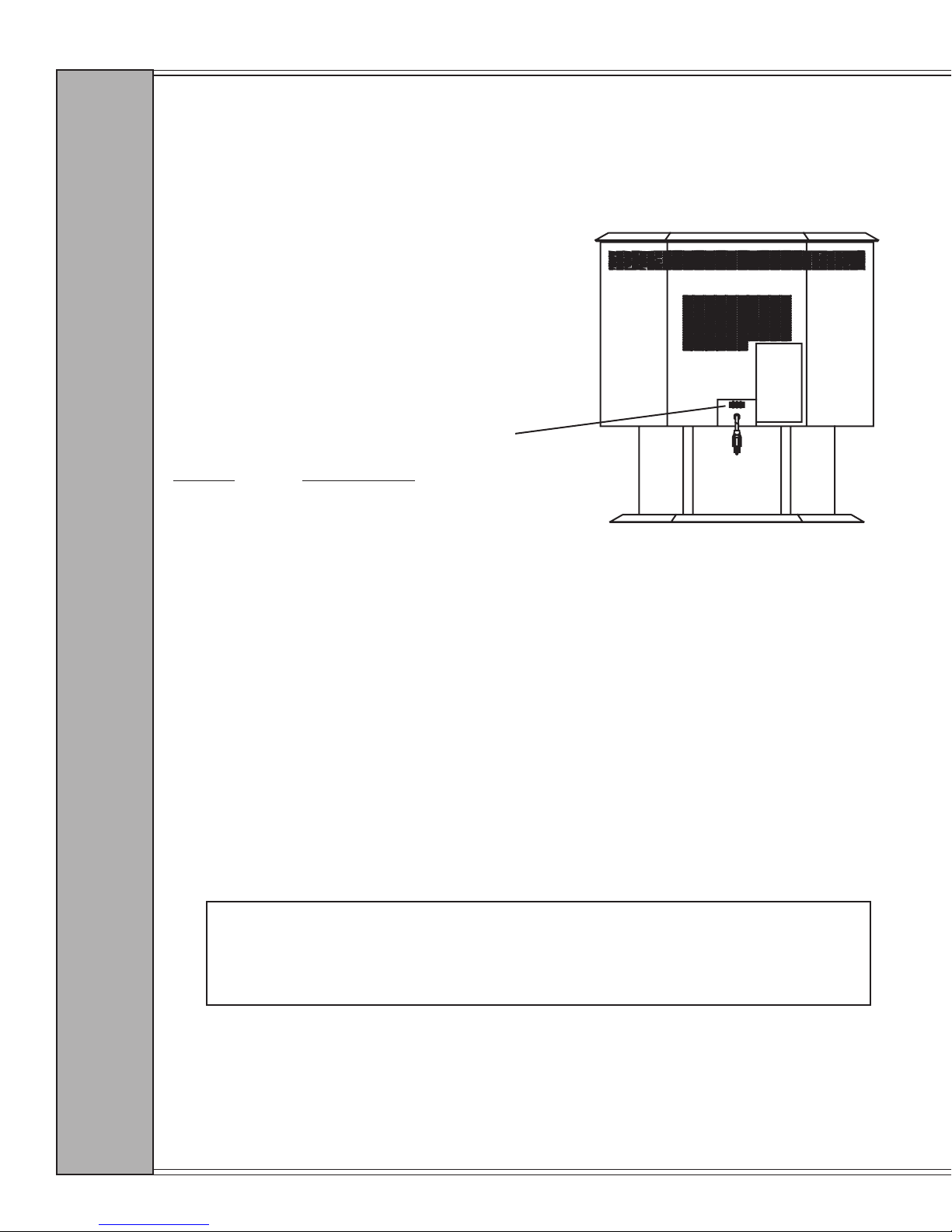
Thermostat
connection block
Connect the thermostat wires to the two center screw terminals in the thermostat connection block,
located at the lower rear of the unit (see gure above). Turn off the manual switch located on
the control panel behind the lower grill.
REMOTE CONTROL
A remote control or a wall switch may be wired to the thermostat terminals. Contact your
Quadra-Fire dealer or service person for details (see page 34 for part number).
FAN POWER CORD
The fan cord is located at the rear of the appliance, and needs to be routed to a three-prong outlet
with correct polarity. Be sure that the appliance is electrically grounded in accordance with local
codes, with a current version of CSA C22 (in Canada), or in the absence of local codes, with the
National Electric Code ANSI/NFPA 70-1987.
WARNING
Do not cut the grounding terminal off under any circumstances.
Do not route the power cord under the body of the appliance due to high temperatures.
I N S T A L L A T I O N :
Page 18
January 2000 January 2000
Page 19
Grand Bay 40 Gas Freestanding
INSTALLATION PROCEDURES
The following procedures show some of the basic installation applications. Remember that
every installation is different, and the installer should adjust to insure that the appliance is
installed properly.
GAS CONNECTIONS
Before hooking up the stove to the gas supply, be sure that the appliance you are installing is
designed for the type of gas being supplied to it. There is a serial number and listing label on the
rear of the appliance that will indicate which type of gas it is designed to utilize. The gas valve
also has a label telling the type of fuel for which it is set up.
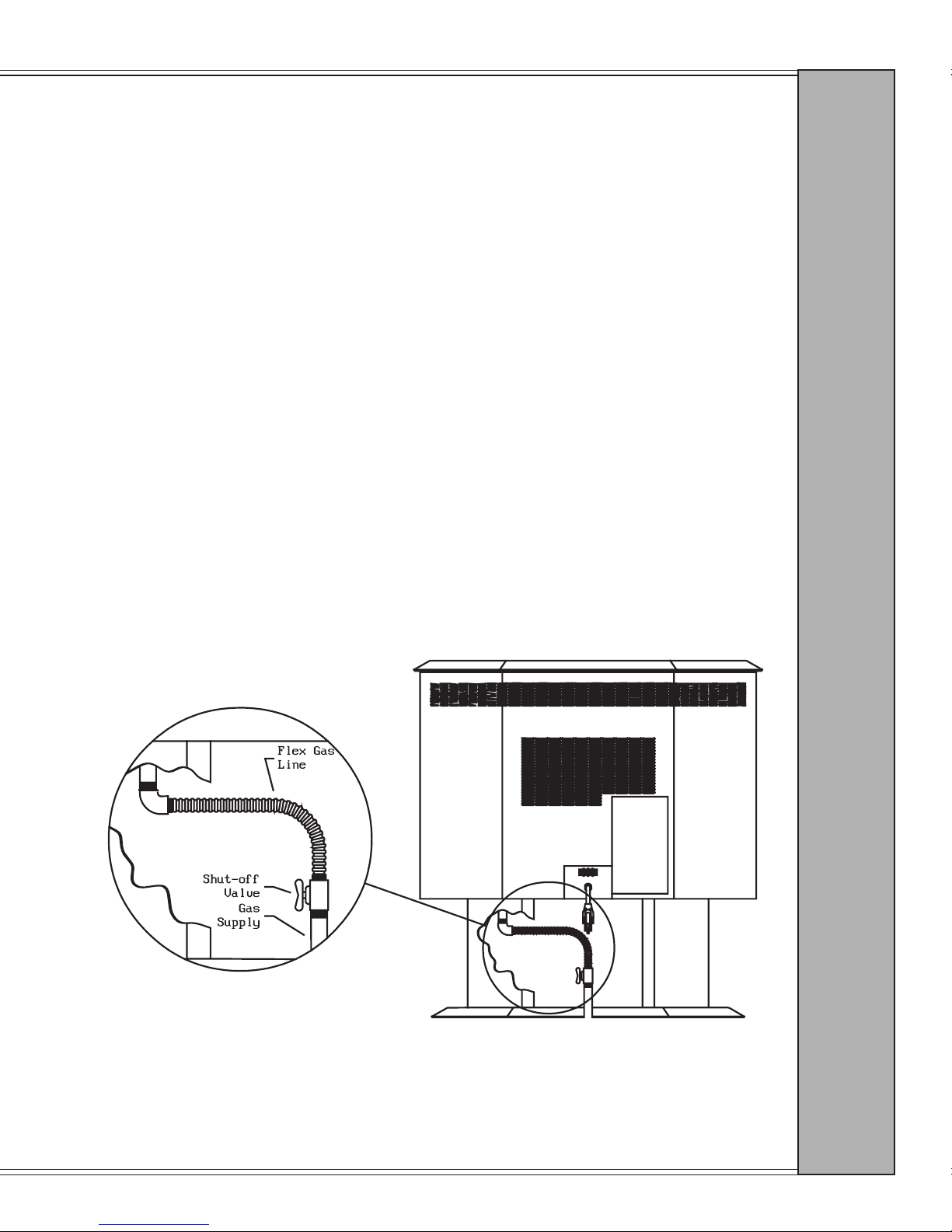
There is a 3/8” gas hookup located under the stove body, with access from the rear through
the pedestal cutout. We recommend connecting the stove with an approved ex gas line, as
shown below. If ex gas lines are not approved in your area, you can connect a hard pipe
to the gas hookup.
I N S T A L L A T I O N :
serial
number
label
C O N N E C T I O N
G A S
Page 19
Page 20
Grand Bay 40 Gas Freestanding
VENT TERMINATIONS REQUIREMENTS
This unit is equipped with a thermal damper, which has been set at the factory. Do not remove or
attempt to adjust.
The vent must terminate vertically with an approved cap, and the vent termination must be located where
it cannot become restricted or blocked by foreign material (for example, snow and leaves). The vent
termination must be above the roof and not below any eaves or overhangs.
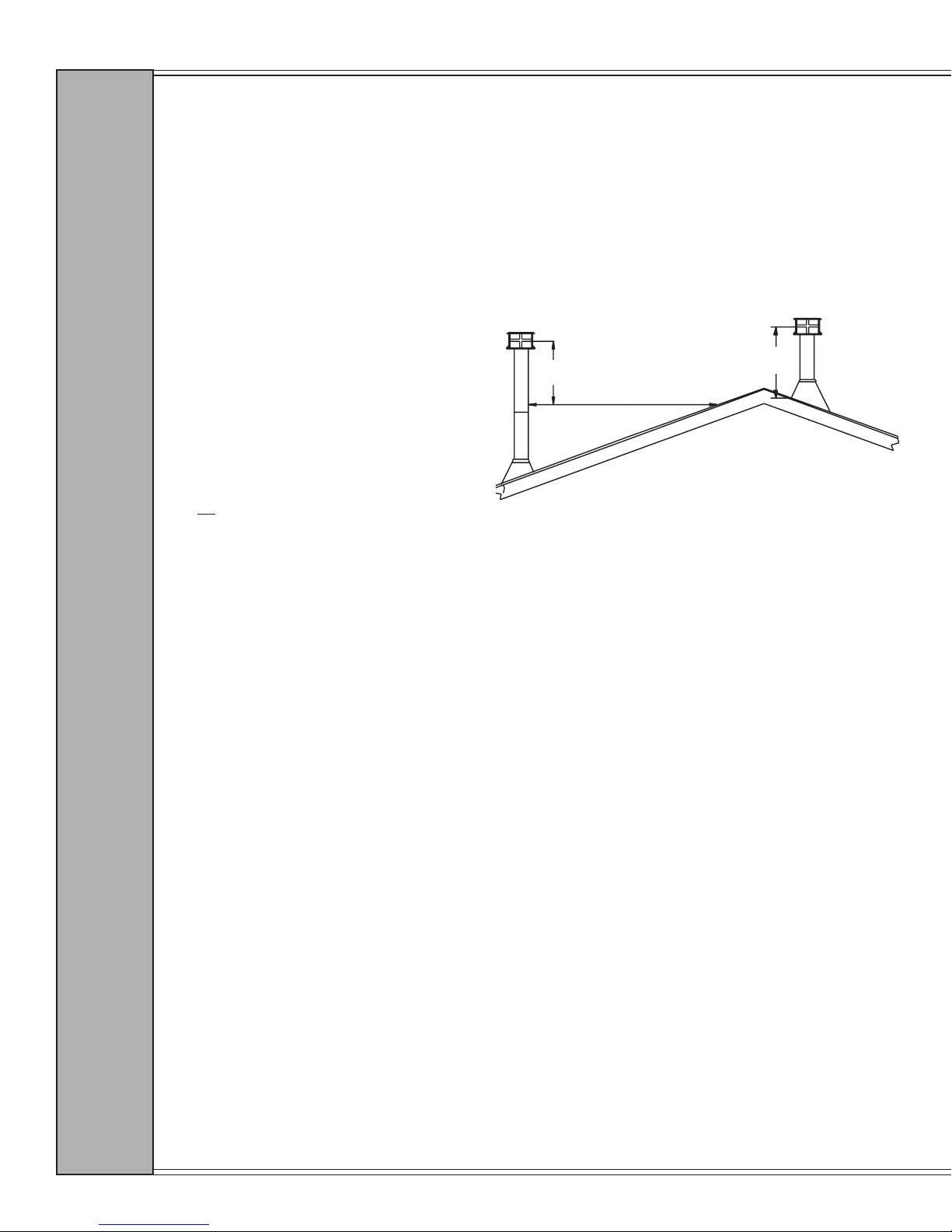
ANSI 223.1, Section 7.6.2 requires a minimum vent height above the roof of 1 foot. On installations with
roof pitch greater than 6/12, there must be at least 3 feet of chimney above the roof level, or 2 feet higher
than any point within 10 feet measured horizontally.
NOTE: The installer must take into
consideration other factors when
determining vent termination height, such
as negative pressure in the home, horizontal
sections and offsets in ue system.
T E R M I N A T I O N S
Use all required venting components when installing this appliance, and do not mix two or more
manufacturers’ products.
EXAMPLES:
1. When the vent passes through the ceiling or upper oor, use of a ceiling support or restop is required.
2. Venting through a wall requires a wall thimble.
3. When vent passes through the roof a proper ashing, storm collar and vent cap are required.
2' Min.
10'
3' Min.
VENTING REQUIREMENTS
PLEASE READ AND FOLLOW ALL VENTING REQUIREMENTS
The GB40 FS must be installed to follow the CAN/CGA B149 (in Canada) or ANSI Z223.1 (in the U.S.A.)
requirements, and any local codes or regulations of the authority having jurisdiction.
WARNING: This appliance must be installed in an area with an adequate amount of combustion and
ventilation air for it to vent and operate properly. Be sure that provisions for adequate air are made
at the time of installation.
THIS APPLIANCE MUST NOT BE CONNECTED TO A CHIMNEY FLUE SERVICING ANOTHER
APPLIANCE.
This appliance is designed to attach to either 4” diameter type B vent or double thickness aluminum ex liner,
running the full length of an existing masonry chimney. A minimum ue height of 12 feet is recommended.
If B vent pipe is used, it must be supported by vent supports supplied by the vent manufacturer.
This appliance has a draft hood installed at the factory, so no external draft hood is required.
V E N T I N G :
B-VENT CHIMNEY REQUIRES A 1” MINIMUM CLEARANCE TO COMBUSTIBLES.
When venting vertically on exterior of structure, use an insulated venting system or properly built chase
structure to help insulate the vent system. This is recommended due to the low ue temperatures of this
appliance. This also helps prevent the possibility of spillage and draft problems occurring.
Page 20
January 2000 January 2000
Page 21
Grand Bay 40 Gas Freestanding
VERTICAL TERMINATIONS AND TERMINATIONS WITH
HORIZONTAL SECTIONS
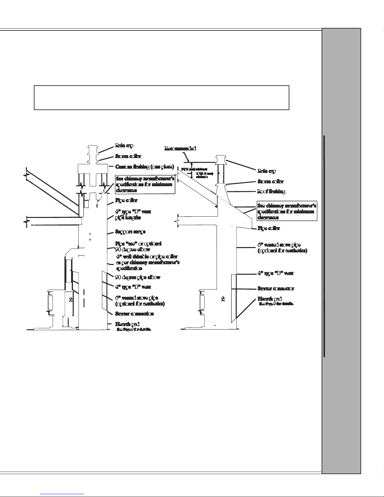
The total horizontal run must not exceed 50% of the total vertical run. Provide a ” rise for each 12”
horizontal run. You must have at least 5 feet of vertical rise.
NOTE: Recommended maximum 35’ vertical.
Recommended maximum offset: Use 4 offsets equaling two 90 degree elbows.
You can place 6” vented stove pipe over the 4” B vent pipe for aesthetics, if you choose. There is an
optional 6” ue collar available for this purpose (see page 34 for part number).
V E N T I N G :
See Page 9 for details.
VENT ATTACHMENT TO FLUE COLLAR
The GB40 FS is equipped with a nondetachable ue collar. The draft hood is stationary to the stove.
When slipping vent over ue collar, the vent should cause the spill strap to lift up. Do not attempt
to rotate the damper on the shaft. This damper should be open when the unit is cold and will close
thermally as the unit heats up.
After running the 4” liner down the existing ue, make sure that the damper plate is securely blocked
open so that it cannot close and pinch or cut the liner. Securely attach the ue collar to the liner. Adjust
and level the stove.
M E T H O D S
See Page 9 for details.
Page 21
Page 22
Grand Bay 40 Gas Freestanding
EXHAUST SPILLAGE AND TESTING PROCEDURE
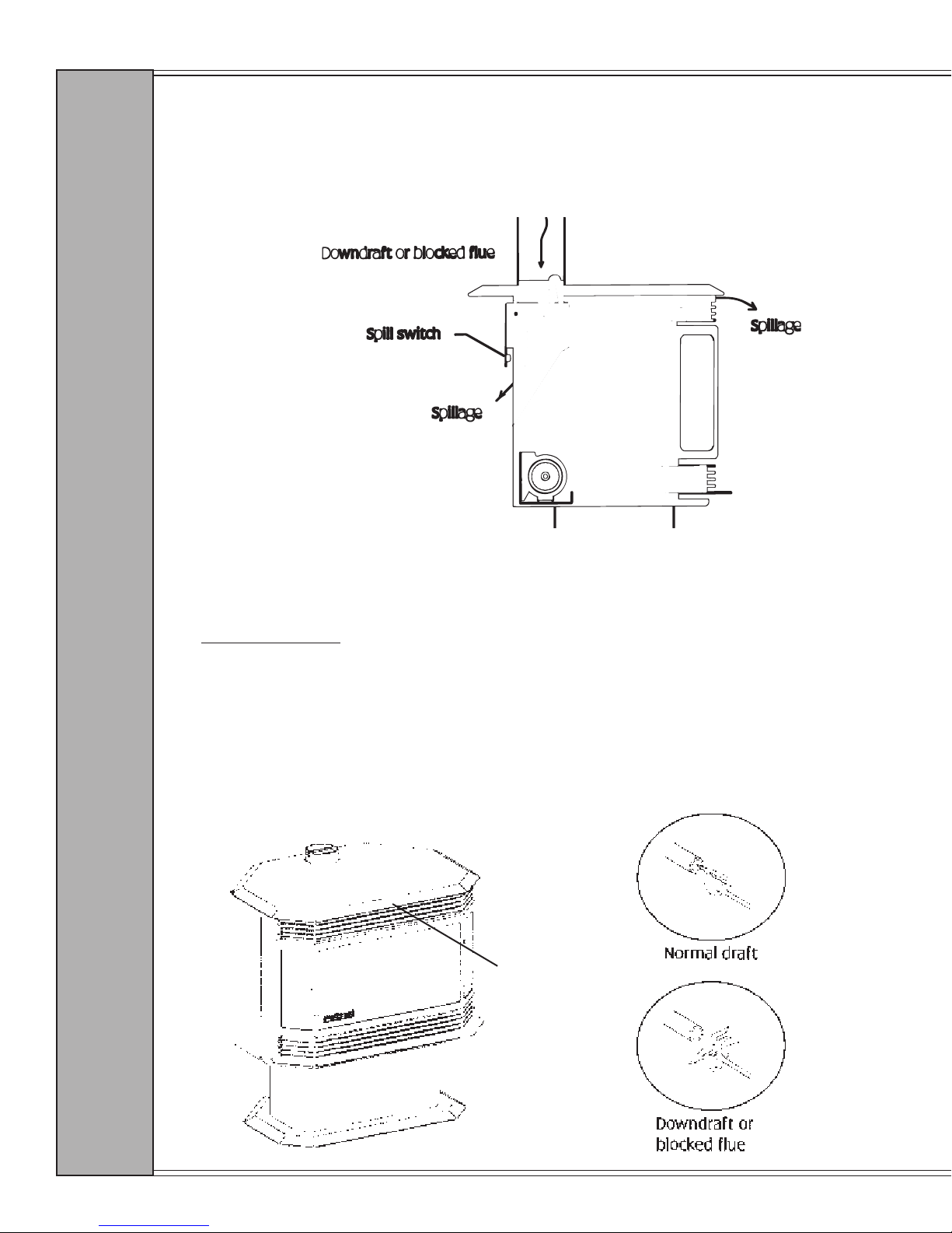
There is a spill switch located on the back of the stove below the draft hood, which is designed to
shut down the stove in the case of a blocked ue or a severe downdraft. The switch acts as a safety
shutoff to prevent carbon monoxide or unburned gas leaking into the room.
S PIL L A G E & T E S TIN G
TO TEST FOR SPILLAGE:
1. Start all exhaust fans in the home, then close all doors and windows in the room.
2. Locate the spill tube, which extends to front of stove at top of grill (as shown below).
3. Turn the appliance on and adjust to highest setting. Leave the fan off.
4. Wait ve minutes, then use a match or other device which creates smoke to test for a draft.
Place the match in front of the spill tube (you may want to place a piece of scrap steel or
aluminum foil under the match to block the natural convection air supplied through the
convection grill). The smoke or ame should be drawn into the spill tube (see Normal draft
below). If it is not, wait ve minutes and try again. If there is still no draw, turn the unit off
and check the venting for the cause. You may need to seek expert advice.
NOTE: For high wind areas, the use of a high wind termination cap is recommended.
Spill Tube End
V E N T I N G :
Page 22
January 2000 January 2000
Page 23

Grand Bay 40 Gas Freestanding
LIGHTING INSTRUCTIONS
FOR YOUR SAFETY READ BEFORE LIGHTING
A. This appliance has a pilot that must be lit manually, using the piezo igniter. When lighting the
pilot, follow these instructions exactly.
B. BEFORE LIGHTING, smell all around the appliance area for gas. Be sure to smell next to the
oor because some gas is heavier than air and will settle on the oor.
WHAT TO DO IF YOU SMELL GAS:
• Do not try to light any appliance.
• Do not touch any electric switch; do not use any phone in your building.
• Immediately call your gas supplier from a neighbor’s phone. Follow the gas
supplier’s instructions.
• If you cannot reach your gas supplier, call the re department.
C. Use only your hand to push in or turn the gas control knob. Never use tools. If the knob will
not push in or turn by hand, don’t try to repair it. Call a qualied service technician. Force or
attempted repair may result in a re or explosion.
D. Do not use this appliance if any part has been under water. Immediately call a qualied service
technician to inspect the appliance and to replace any part of the control system and any gas
control that has been under water.
LIGHTING INSTRUCTIONS
L I G H T I N G
1. STOP! Read the safety information prior to this section.
2. If using a thermostat, set the thermostat to the lowest setting. Pull down the grill on appliance
front to expose the control panel, and turn the ON/OFF switch to OFF.
3. Turn off all electric power to the appliance.
4. Open glass front.
5. Push in gas control knob slightly and turn clockwise to “OFF”.
NOTE: Knob cannot be turned from “PILOT” to “OFF unless knob is pushed in slightly. Do
not force.
6. Wait ve (5) minutes to clear out any gas. Then smell for gas including near the oor. If you
smell gas, STOP! Follow “B” of the safety information in the section prior to this. If you don’t
smell gas, go to the next step.
7. Turn knob on gas control counterclockwise to “PILOT”.
8. Push in control knob all the way and hold in. Immediately light the pilot by repeatedly
depressing the piezo igniter until a ame appears.
NOTE: The pilot should be visible through the door glass in the lower left hand corner between
the front and rear logs. As piezo igniter is depressed a blue spark can be seen. When lit,
the ame will be visible.
Continue to hold the control knob in for about thirty (30) seconds after the pilot is lit. Release
knob and it will pop back up. Pilot should remain lit. If it goes out, repeat steps 5 through 8.
• If the knob does not pop up when released, stop and immediately call your
service technician or gas supplier.
• If the pilot will not stay lit after several tries, turn the gas control knob to “OFF”
and call your service technician or gas supplier.
9. Close glass front.
10. Turn gas control knob counterclockwise to “ON”.
11. If you are not using a thermostat, turn ON/OFF switch to ON. If you are using a thermostat,
leave the switch in the OFF position and set thermostat to desired setting.
TO TURN OFF GAS TO APPLIANCE
1. If using a thermostat, set it to lowest setting.
2. Turn off all electric power to the appliance if service is to be performed.
3. Pull down grill on front of appliance to expose control panel.
4. Push in gas control knob slightly and turn clockwise to “OFF. Do not force.
5. Close grill.
Page 23
Page 24
Grand Bay 40 Gas Freestanding
FIRST FIRE
NOTE: Never operate this appliance with the door open.
NOTE: No electrical power supply is required for the gas control to operate. Standing pilot
allows the valve to operate with manual switch or millivolt thermostat.
WARNING: When the appliance is equipped with a 24 karat gold-plated door,
you must clean all the ngerprints and oils from the gold surface before ring the
appliance for the rst time. Use a glass cleaner or vinegar and a towel to insure
that the oil is removed. If not cleaned properly before firing, fingerprints or
oil can cause permanent markings on the gold plating. After the gold plating is
cured, the oils will not affect the nish and little maintenance is required; just
wipe clean as needed.
Before rst ring the stove, read the owner’s manual to become familiar with the stove’s
features, controls, and cautions for operation.
Remove all labels from glass before starting your rst re in this stove.
Plug power cord into a properly installed outlet for blower operation.
The blower system has an on/off thermo snap disc that will turn the fan on automatically
when the proper temperature is reached, and will turn the blower off when it cools down in
order not to blow cool air after shut down.
OPERATION CONTROLS
The operation controls are located on the control panel behind the lower grill, and consists
of the following:
1) The rheostat, which controls the fan speed. 2) The manual on/off switch. 3) The piezo
igniter. 4) Valve On/Off and HI/LO control knob.
Follow the lighting instructions on page 21 of this manual, or on the metal sheet chained
in lower grill area by gas control valve.
During your rst re in the appliance, you may notice an odor and steam coming from the
stove. This is normal, it is the high temperature paint nishing its curing process. Open the
door and/or windows in the home or structure for ventilation.
We recommend that you initially cycle the stove on and off, heating the stove to curing
stage for several minutes, and then turn it off to cool for ve minutes. Then turn the stove
back on, and burn until the steam and/or odor no longer appears. If odor persists, turn
F I R S T F I R E
the gas supply to the stove off, and call your local dealer or authorized service person
to inspect the appliance.
WARNING: Extended use of the appliance on high without using the blower can
cause overheating conditions in the appliance, and result in tarnishing or discoloration
of the gold plating on the door. It is recommended that when the blower is not in use,
you should operate the stove at lower valve control settings or cycle the appliance
on and off for short periods.
Page 24
January 2000 January 2000
Page 25
Grand Bay 40 Gas Freestanding
MAINTENANCE
CLEANING AND INSPECTION
At least once yearly, preferably before the heating season, have the insert and venting system
cleaned and inspected by a qualied service person. This will insure proper and safe operation
throughout the year.
CLEANING THE BURNER TUBES
1. Turn off pilot light.
2. Open door.
3. Remove logs and glowing charcoals.
4. Vacuum burner compartment, especially around orice and
primary air openings.
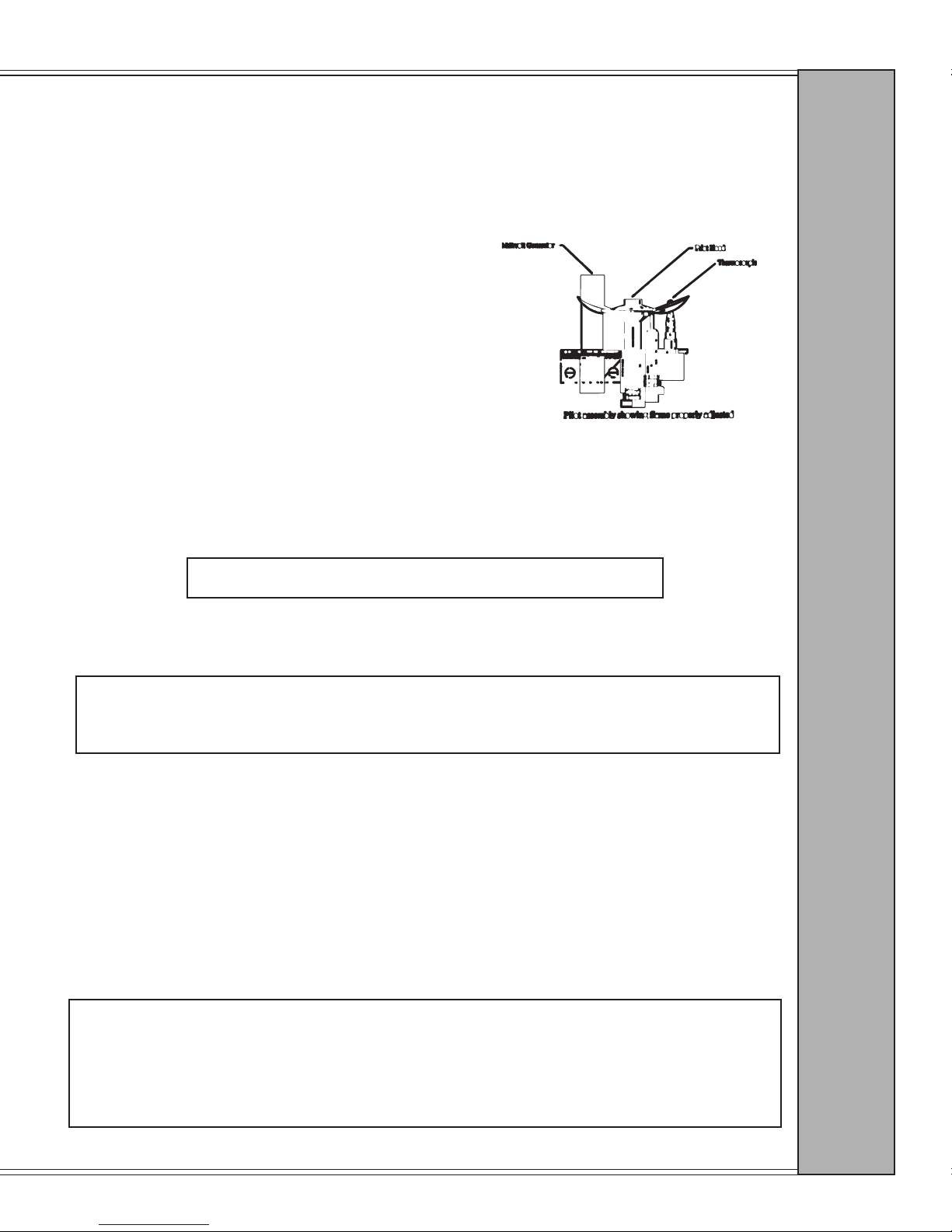
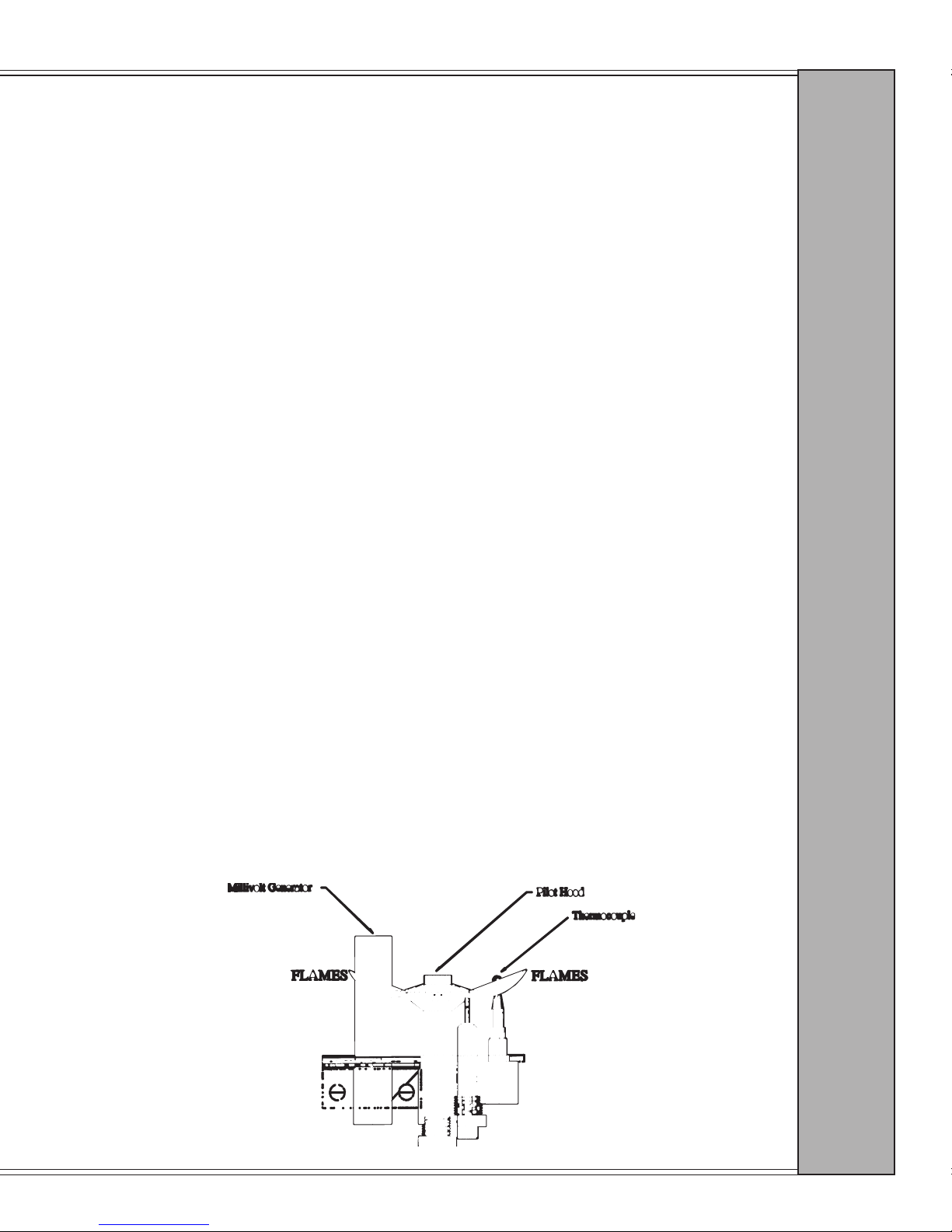
5. Relight pilot. Check to insure ames are touching
millivolt generator (see diagram at right).
6. Reinstall logs. See page 14 for log installation instructions.
7. Close and latch door.
8. Recheck pilot and main burner to insure they are operating correctly.
GLASS CLEANING
WARNING: DO NOT CLEAN GLASS WHEN HOT.
1. Turn off pilot.
2. Open door.
M A I N T E N A N C E
WARNING:
DO NOT USE ABRASIVE CLEANERS ON GLASS OR GOLD SURFACES.
3. Using regular glass cleaner, spray the glass surface and wipe with soft cloth or clean paper
towel until surface is dry.
4. Close and latch door.
5. Relight pilot and check main burner’s operation.
NOTE: If you observe a white lm on the door glass, use a hard water deposit glass cleaner
or contact your dealer.
NOTE: Do not use abrasive materials or chemical cleaners.
WARNING: Running the appliance on high for extended periods without the use of
the blower can cause the appliance to overheat, resulting in tarnishing or discoloring
of the gold plating on the door. We recommended that you operate the appliance
at lower valve control settings, or cycle the appliance on and off for short periods
when the blower is not in use.
Page 25
Page 26
Grand Bay 40 Gas Freestanding
MAINTENANCE (cont.)
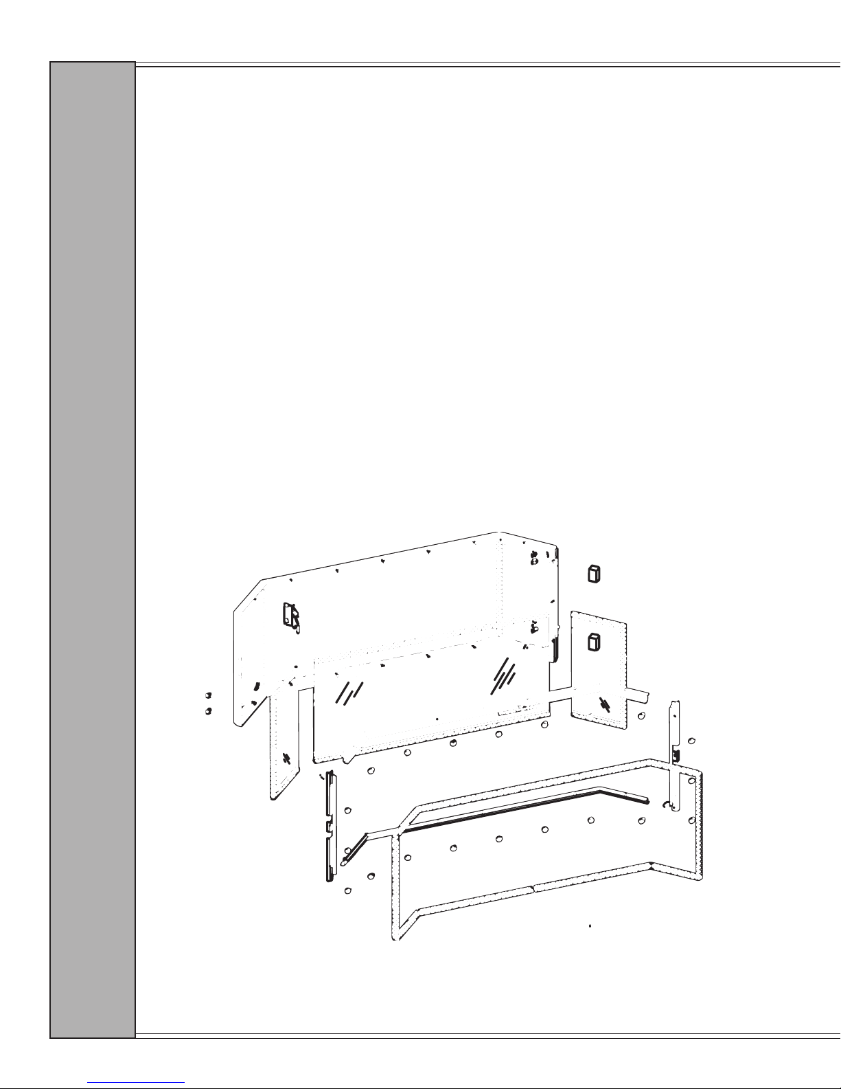
GLASS REPLACEMENT (posted doors only; full view doors must be returned to the
manufacturer for glass replacement)
WARNING: USE ONLY MANUFACTURER-SUPPLIED REPLACEMENT PARTS (PART
NUMBER 842-1360 SIDE GLASS; 842-1280 CENTER GLASS).
1. Open and remove stove door. Place door on a soft surface.
2. Remove rope gasket from door frame.
3. With a 5/16” wrench, remove all nuts that hold glass retaining bars in place. Remove
retaining bars.
4. Be very careful when lifting old glass out of the door frame.
5. Insert new glass and reinstall in reverse order. Be sure to use new door gasket (part
number 842-1420, 5/8” x 96” rope).
NOTE: Be sure to clean glass and gold door before lighting stove.
M A I N T E N A N C E
Page 26
January 2000 January 2000
Page 27
Grand Bay 40 Gas Freestanding
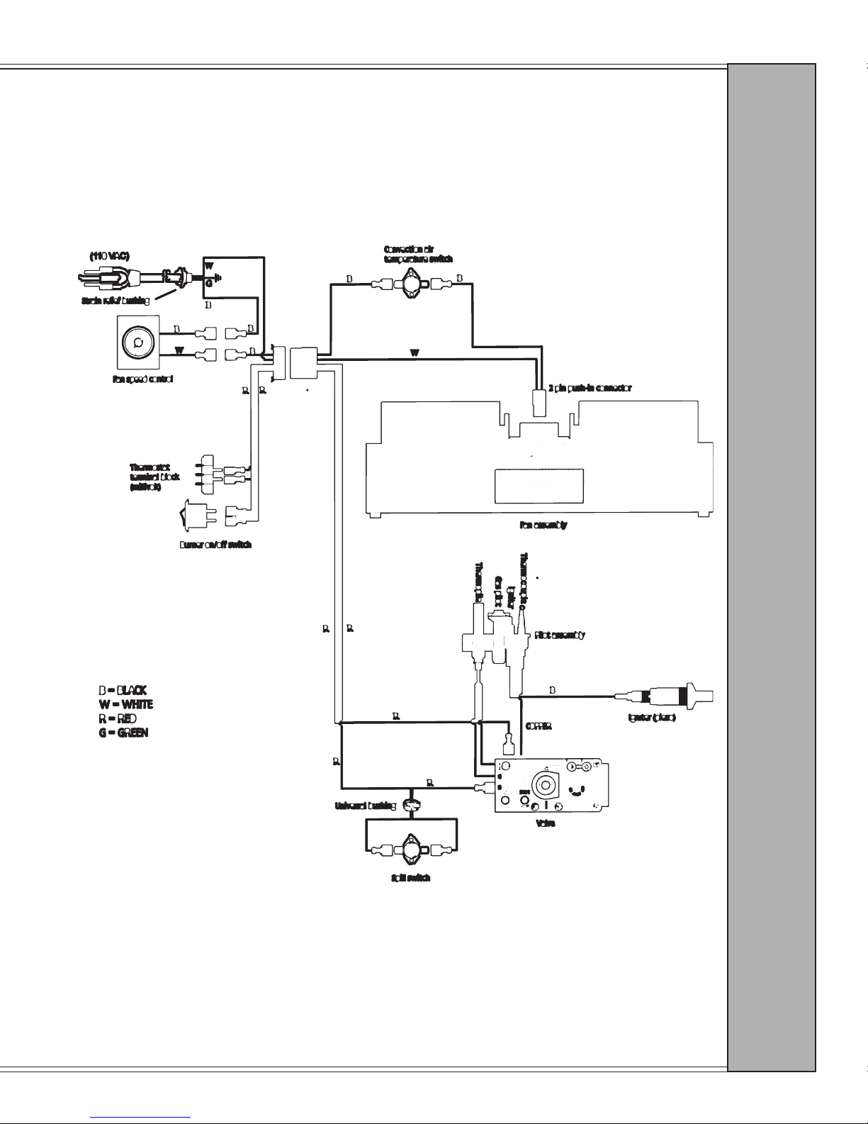
SCHEMATICS
S C H E M A T I C S
Page 27
Page 28
Grand Bay 40 Gas Freestanding
BLOWER AND SNAP DISC REPLACEMENT
NOTE: BLOWER DOES NOT REQUIRE LUBRICATION. HOWEVER, WE
RECOMMEND VACUUMING OR BRUSHING OFF DUST OR LINT FROM THE FAN
BLADES AS NEEDED.
BLOWER AND SNAP DISC REMOVAL
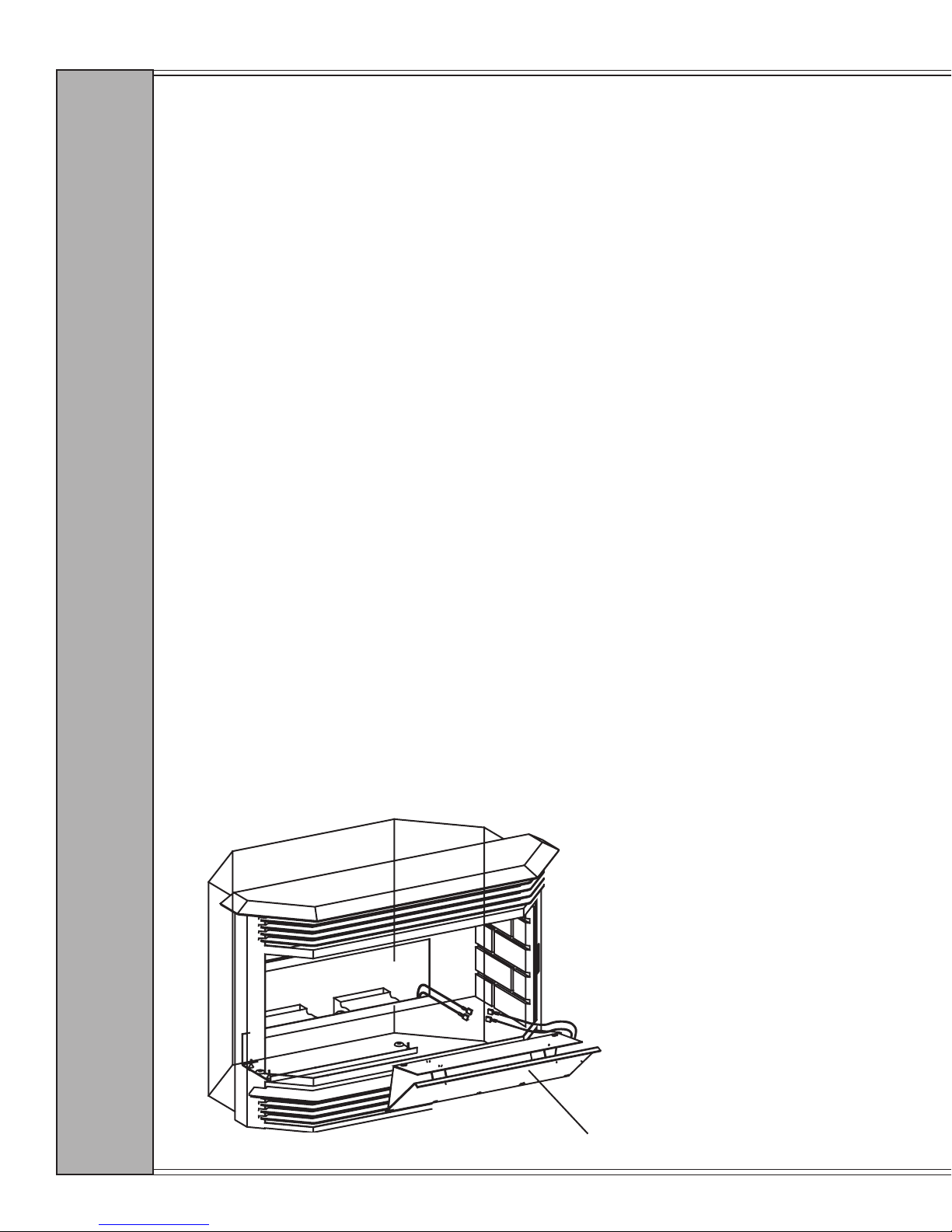
This appliance is equipped with a 170 cfm convection blower that is automatically controlled
by a temperature-sensing snap disc (145º). The blower has a speed control located on the
control panel behind the lower grill. The blower is located behind the rear access panel at the
back of the rebox. It will be necessary to remove the log set to remove the access panel.
There are twelve screws that hold the panel in place. To replace or access the blower or snap
disc, follow the instructions below and observe the drawing on the following page.
1. Disconnect power from the unit and turn off gas supply.
2. Remove the log set (see log installation, page 14, for reinstallation).
3. Remove the rear log support, then remove the eight screws that hold the rear access
panel/heat shield assembly in place.
4. To remove rear access panel/heat shield assembly, slightly tip forward and remove from
rebox. The snap disc is located on the back of this assembly. To replace snap disc,
slide it out of its holder before removing heat shield from the rebox. If the snap disc is
all that needs to be replaced, reinstall assembly and log set in reverse order. For blower
removal, continue to the next step.
5. Disconnect the blower wiring. This blower is held in place by rubber grommets that
slide over two metal studs welded to the bottom of the unit. Gently lift blower off
mounting studs and remove.
6. Reinstall in reverse order.
IMPORTANT! The blower is equipped with a three prong (grounding) plug for your
protection against shock hazard, and should be plugged directly into a properly grounded three
prong receptacle. Do not cut or remove the grounding prong from this plug.
B L O W E R / S N A P D I S C
Page 28
Rear Access Panel/Heat Shield Assembly
January 2000 January 2000
Page 29
Grand Bay 40 Gas Freestanding
TROUBLESHOOTING
I. PILOT WON’T LIGHT
A. Make sure valve setting is in the pilot position.
B. Check for spark at igniter.
1. If no spark:
a. Check the wiring between the piezo and the igniter. If bad, x wiring; if good, you may
have a faulty piezo or cracked ceramic on the electrode.
b. Call your Quadra-Fire dealer.
2. If there is a spark:
i. Try to light the insert with a match. The ame should either light or utter.
a. If the ame utters but does not light the pilot, there probably is air in the line. Hold
ame to pilot hood, then bleed the line until gas comes through.
b. If the match ame does not utter, make sure the gas is turned on and be sure you are
pushing the knob in all the way. If this still doesn’t help, you may be dealing with a
bad valve, a blocked pilot orice, or a kinked pilot line.
C. Call your dealer or authorized service person.
II. PILOT GOES OUT WHEN KNOB IS RELEASED
A. Wait ve minutes and try again. If the pilot still goes out, try again and hold the knob in longer.
B. If the problem persists, call your dealer or authorized service person.
III. PILOT LIGHTS BUT BURNER WON’T IGNITE
A. Make sure the knob is turned to the “on” position.
B. Turn the thermostat up.
C. If there is no thermostat, ip the manual switch on the control panel behind the lower grill.
If the burner does not light, short out the thermostat screws on the face of valve marked
TH and TPTH. If the burner lights, you may have a problem in the wiring of the stove,
and it should be checked.
D. Check the thermostat and thermopile connections at the valve, and tighten or reconnect if
needed.
E. If the burner still will not ignite, you may have a bad valve; call your dealer or authorized
service person.
F. Refer to page 16, which covers operation of spill switch and testing.
T R O U B L E S H O O T I N G
Check the pilot and burner ames periodically. When properly adjusted, they should look like the
flames in the illustration below. Call your dealer or authorized service person to have the pilot
properly adjusted.
Pilot assembly showing ame properly adjusted
Page 29
Page 30
Grand Bay 40 Gas Freestanding
CONVERSION KIT INSTRUCTIONS
NG Part #842-1361 LP Part#842-1641
Kit Contents:
(1) Pilot Line
(3) Burner Orices
(1) Pilot assembly
(1) Conversion Sticker
(1) Lox-it Fitting
(1) HI/LO Valve Regulator with instructions
Directions:
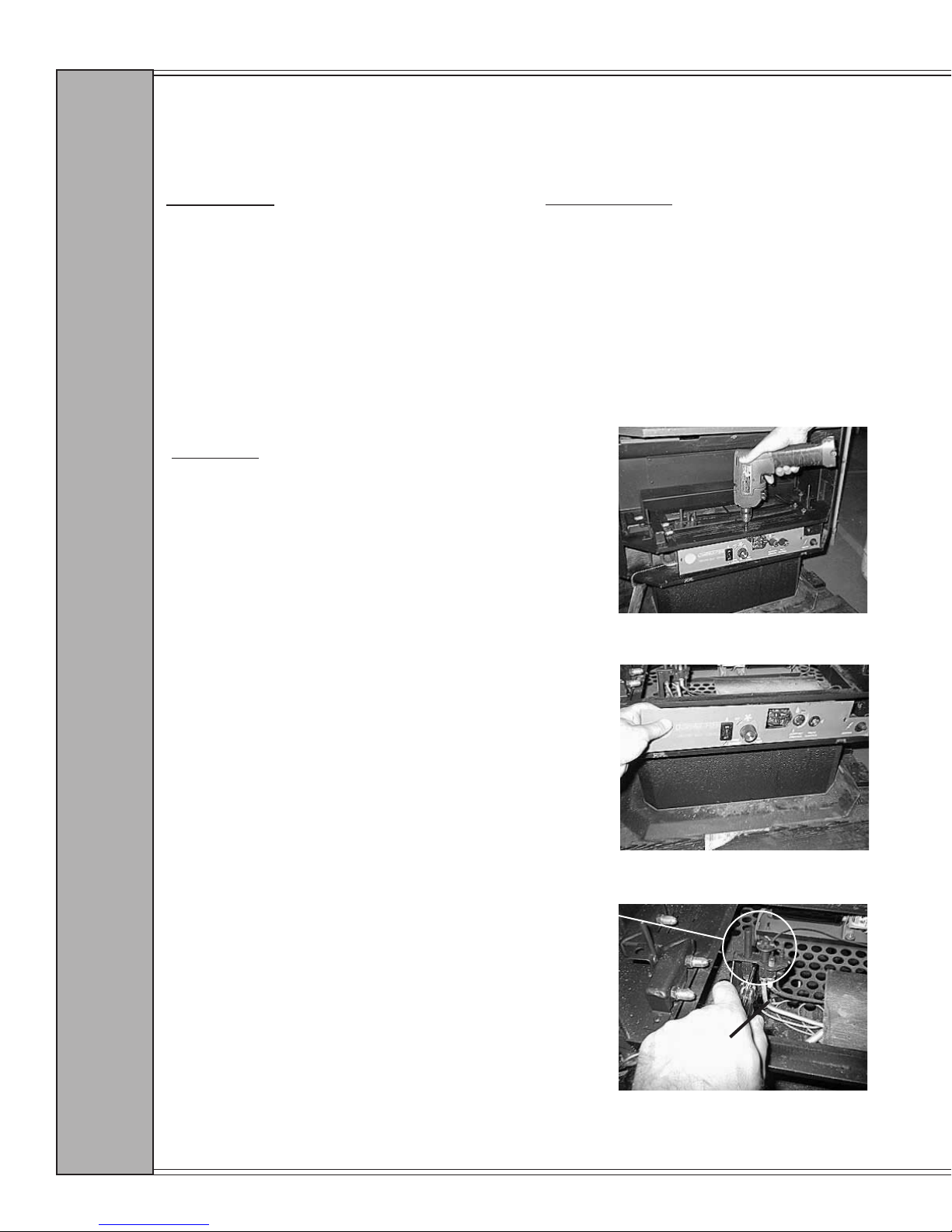
1. Remove door, logs, burner tubes,
nuggets and rear log shelf.
2. Remove 4 screws from burner pan
and remove. See Figure A
Tools Required:
3/8" socket and open end wrenches
7/16" socket and open end wrenches
10 mm open end wrench
TH20 torque screwdriver
Phillips screwdriver
Gas Leak Detector
Manometer
FIG. A
3. Remove control panel cover.
See Figure B
4. Remove two screws on pilot tower
assembly and disengage assembly.
See Figure C
5. Use 7/16" wrench to disconnect
pilot line at valve.
C O N V E R S I O N
FIG. B
Pilot Tower
FIG. C
Pilot Line
Page 30
January 2000 January 2000
Page 31
Grand Bay 40 Gas Freestanding
CONVERSION INSTRUCTIONS, CONT.
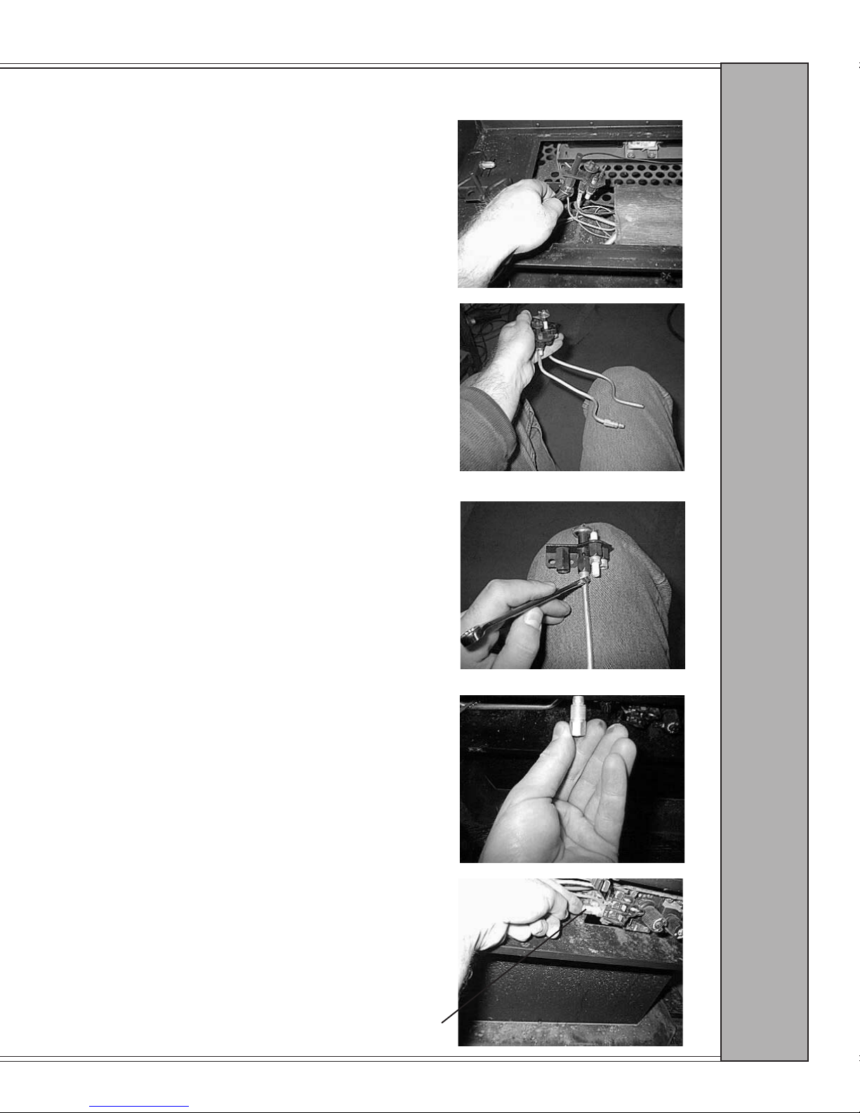
6. Disconnect thermocouple, thermopile
and piezo wire connector from existing
pilot assembly.
See Figure D
7. Align old pilot line side by side with new
line and pre-bend new line into correct
position. See Figure E
8. Insert new pilot line into new pilot
assembly and tighten tting with 10mm
wrench. See Figure F
Fig. D
C O N V E R S I O N
Fig. E
NEW
OLD
Fig. F
9. Insert new lox-it tting into valve and
hand tighten. See Figures G & H
Lox-it tting in valve.
Fig. G
Lox-it tting
Fig. H
Page 31
Page 32
Grand Bay 40 Gas Freestanding
CONVERSION INSTRUCTIONS, CONT.
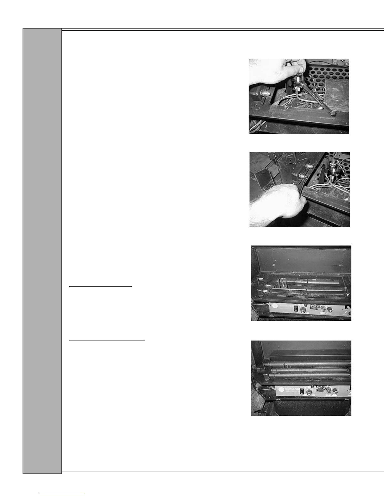
10. Reinstall Thermocouple and Thermopile into pilot assembly and
reconnect piezo wire connector. See
Figure I
11. Secure pilot assembly to pilot tower
with 2 screws.
Fig. I
12. Insert pilot line into lox-it tting
at valve and tighten tting witih
wrench.
13. Use 3/8" socket wrench to remove
existing burner orices and install
new burner orices. See Figure J
NOTE! Ensure that orice size for
each burner tube and your altitude is
correct, as stated below:
Altitudes of 0-2000'
NG LP
Front #54 #65
Middle #53 #62
Rear #39 #53
Altitudes of 2000'-4500'
NG LP
Front #55 #66
Middle #54 #63
Rear #40 #54
C O N V E R S I O N
Fig. J
Fig. K
Fig. L
14. Reinstall burner pan and burner
tubes. See Figures K & L
Page 32
January 2000 January 2000
Page 33
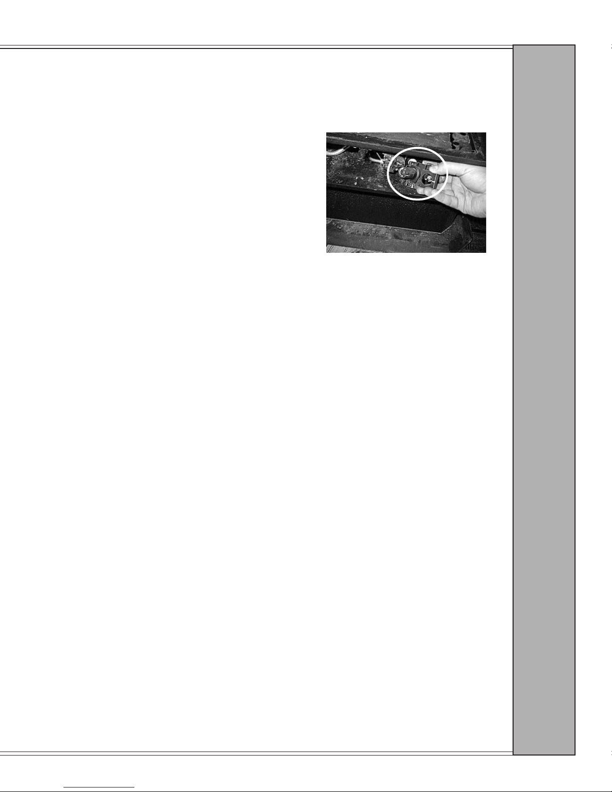
Grand Bay 40 Gas Freestanding
CONVERSION INSTRUCTIONS, CONT.
15. Remove and replace manual regulator. See instructions provided with
part. See Figure M
16. Light pilot and leak test.
17. Ignite burners and check HI/LO regulator for leaks.
18. Apply conversion sticker to unit.
19. Turn unit OFF and reinstall components in reverse order.
Fig. M
C O N V E R S I O N
Manual Regulator
Page 33
Page 34

Grand Bay 40 Gas Freestanding
ACCESSORIES
These may be ordered through your Quadra-Fire dealer.
812-2880 Thermostat, manual
811-0520 Thermostat, electronic set back
841-0320 Remote control
841-0540 6” ue collar
SERVICE PARTS
842-1260 Bafe
842-1351 Blower, 170 cfm
842-0380 Blower cord, 6 foot
842-0250 Millivolt generator (thermopile)
842-0390 Thermocouple
842-0250 Thermopile
842-1880 Pilot Assembly NG
842-1890 Pilot Assembly LP
842-1400 Blower Snap Disc
812-0330 Spill Snap Disc
842-1660 Rocker switch (ON/OFF)
842-2300 Speed control knob
842-0370 Speed Control
842-0360 Piezo igniter
842-2080 Piezo wire
842-1360 Side H-Channel glass
842-1280 Front H-Channel glass
842-3090 H-Channel Gold Door
842-3100 H-Channel Black Door
842-1761 Full view gold door
842-0971 Replacement Door Latchbox
842-1420 Door rope, 5/8" x 96"
842-1390 Door hinge assembly
842-1641 LP conversion kit
842-1631 NG conversion kit
842-1650 Wire Harness
842-1620 Owner’s manual
A C C E S S O R I E S
842-0330 Gray Brick Panel Set
842-2030 Gray Left Side Brick
842-2190 Gray Right Side Brick
842-2270 Gray Left Floor Brick
842-2280 Gray Right Floor Brick
842-2290 Gray Front Brick
842-0341 Log Set Split-Deep Bark
842-3450 Log-Front Split-Deep Bark
842-3680 Log-Back Split-Deep Bark
842-3690 Left Twig Split-Deep Bark
842-3510 Right Twig Split-Deep Bark
841-0370 Nuggets, charred
Page 34
January 2000 January 2000
Page 35
Grand Bay 40 Gas Freestanding
GAS APPLIANCE LIMITED LIFETIME WARRANTY
Aladdin Hearth Products, warrants this gas heating appliance to the original purchaser for the lifetime of the
appliance, to be free from defects in material and workmanship. This warranty gives you specic legal rights;
you may have other rights which may vary from state to state.
This limited Lifetime Warranty covers items such as but not limited to combustion chambers, burners,
gas logs, and gold plating.
All parts to be replaced must be returned to an authorized Aladdin Hearth Products dealer at purchaser’s expense
for inspection and approval by Aladdin Hearth Products prior to repair or replacement. No repair or replacement
costs will be honored without approval of Aladdin Hearth Products.
This new Quadra-Fire product must be installed by a competent, authorized service contractor. It must be
installed and operated at all times in accordance with the Installation, Operation and Maintenance Instructions
furnished with this product, as well as any applicable local and national codes. Any alteration, willful abuse,
accident, or misuse of the product shall void this warranty.
W A R R A N T Y
Any installation, construction, transportation, or other related costs or expenses arising from defective part(s),
repair, replacement, etc., will not be covered by this warranty, nor will Aladdin Hearth Products assume
responsibility for them. Further, Aladdin Hearth Products will not be responsible for any incidental, indirect,
or consequential damages, except as provided by law.
All electrical components such as but not limited to blowers, wiring, thermodisc switches and gas valves are
covered by Aladdin’s one year warranty program.
Aladdin Hearth Products will not be responsible for any alteration to the unit which causes sooting that results
in damage to the interior of the building in which this appliance is installed.
This warranty is void if the stove has been operated in atmospheres contaminated by chlorine, uorine, or other
damaging chemicals, or the stove is subjected to prolonged periods of dampness or condensation.
This limited Lifetime Warranty does not extend to or include paint or ceramic insulating materials. It does
not cover installation or operational related problems such as overring, or negative air pressures caused by
mechanical systems such as furnaces, fans, clothes dryers, etc.
This limited Lifetime Warranty does not apply to hearth components or other accessories used in conjunction
with the installation of this product not manufactured by Aladdin Hearth Products.
This limited Lifetime Warranty is effective on all gas stoves sold after September 1, 1996, and supersedes
any and all warranties currently in existence.
IMPORTANT
This warranty is not valid unless the warranty registration card has been properly completed in full and returned
within 10 days from the date of purchase to Aladdin Hearth Products, 401 North Wynne Street, Colville, WA
99114-2153. Proof of purchase is required to secure warranty.
Copyright Aladdin Hearth Products, July 1997 (842-1620)
Page 35
Page 36
Grand Bay 40 Gas Freestanding
OWNER’S MANUAL
 Loading...