

Page 1
'.-
\at
'5
auAD66
Compact
Disc Player
Service
Data
Quad
Electroacoustics
Ltd
St. Peters Road Huntingdon
Cambs
PE18
7DB England
Telephone
0480
52561
Fax
0480
413403
-r
OSCDIED
Page 2
ü
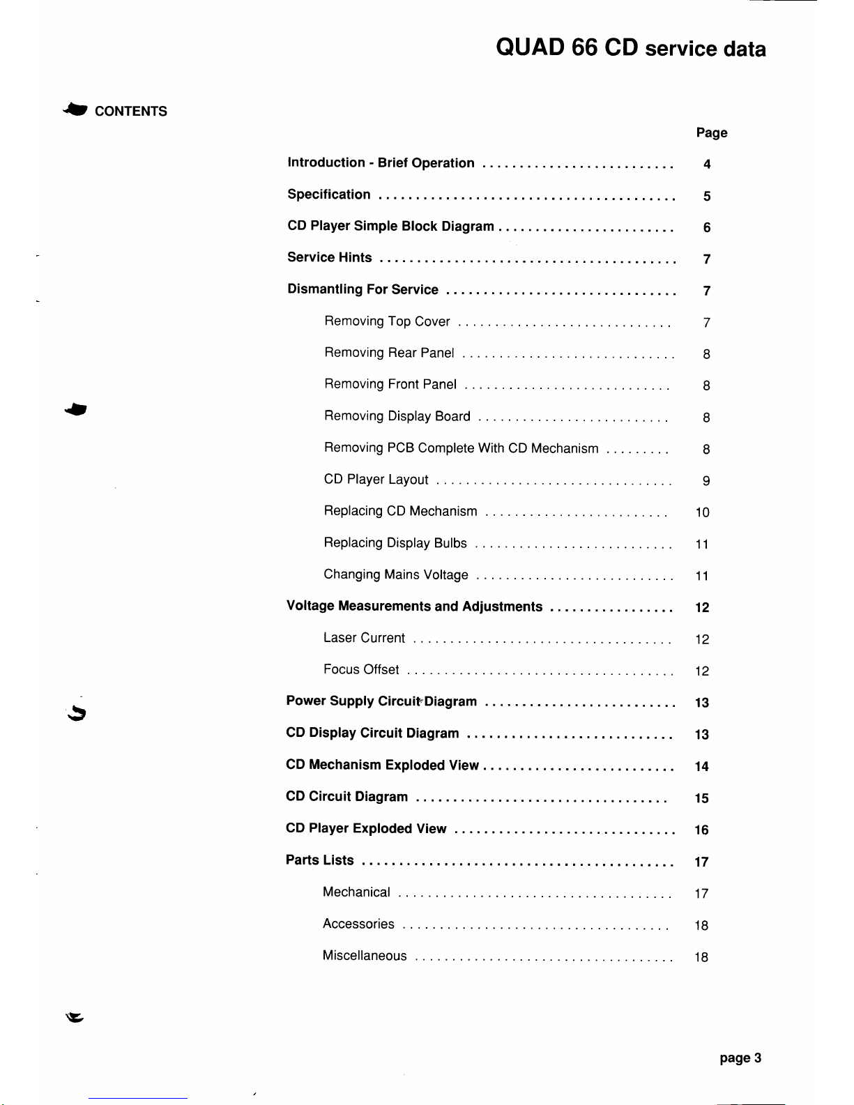
coNTENTS
QUAD
66
CD service
data
Page
4
5
6
7
7
7
-
Introduction
-
Specification
Brief
Operation
CD Player
Simple Block
Diagram
Service
Hints
Dismantling
For
Service
Removing
Top
Cover
Removing
Rear
Panel
Removing
Front
Panel
Removing
Display
Board
Removing
PCB
Complete With
CD
Mechanism
CD Player
Layout
Replacing
CD
Mechanism
Replacing
Display
Bulbs
Changing
Mains
Voltage
Voltage
Measurements
and
Adjustments
Laser
Current
Focus
Offset
Power
Supply
Circuit"Diagram
CD Display
Circuit Diagram
CD
Mechanism
Exploded
View
CD
Circuit Diagram
GD Player
Exploded
View
Parts
Lists
Mechanical
Accessories
8
8
8
8
9
10
11
11
12
5
12
12
13
13
14
15
16
17
17
18
18
v
Miscellaneous
page
3
Page 3
QUAD
66 CD
service
data
3
INTRODUCTTON
The
Quad
CD
player
is
designed
for the serious
music listener.
lt has
the
minimum
number
of
controls
and
funclions on the assumption
that the
serious
music
listener wishes to
hear music
in
the
order
in which it was
written and
will normally start
from the
beginning of
a disc. However simple
programming
permits
tracks
to be selected
and
played
in any sequence.
The
player
disc drawer
will accept
compact audio
discs
in
the
'normal'
and
'CD
single'
format
without any special
adapters.
The main operating
controls
are separated
from the
player
and all
major
functions are available
via a
remote control
unit, a compact
hand
held
type
being
supplied as
standard
More
than
one
remote control
can be used
and
it is not necessary to
point
the unit
at the CD
player
as
is often the
case
Performance of the Quad
CD
player
is as accurate
as it is
possible
to
achieve
by careful
design,
selection of
componenls
and rigorous test
orocedures.
BRIEF OPERATING
o Switch on.
INSTRUCTIONS
O
Press
drawer
button.
The drawer compartment
will open.
a
Place disc,
label side
up,
in
drawer
compartment.
a Gently
push
front ol drawer.
lt will close by
itself .
a
The disc
will now start
to
play
from the beginning
O
For full remote
control
operation
and track
tt
programming refer to appropriate
section
of instruction
book.
page
4
v
Page 4

0
sPEcrFrcATroN
Main
Unit
OPeration:
ü
tr
\J
QUAD
66
CD service
data
Full function
by
infrared remote
control
or
simple direct
to
play
operation without
remote
control.
Number
of channels: 2
Frequency
response:
20 - 20,000
Hz.
Amplitude
linearity:
+/-
0.1 dB
20
-
20,000 Hz.
Phase linearity:
+/-
0.5 deg 20 - 20,000
Hz.
Dynamic
range:
96 dB 20 - 20,000 Flz.
Signal/noise ratio:
96 dB
2A
-
20,000 Hz.
Channel
separation:
93 dB
20
-
20,000 Hz.
Total harmonic
distortion: 0.003% 20 - 20.000 Hz.
Wow
and
flutter:
Below
measurement levels.
DiA
conversion:
Quadruple
oversampling
(176.4kH2)
with
digital
filter
and two
16-bit
D/A
converters.
Error
correction
system:
Cross
interleaved
Reed
Solomon
Code
Audio
Output:
(crRC).
2 V rms
max.
300
mV
on
normal
programme
material.
Minimum load impedance
10
kO.
Optical
readout
system: Laser
semi-conductor A/GaA
wavelength
800
nm.
Sampling frequency.
44.1 kHz.
Digital
output: For
digital signal
processors.
Remote
control
Interface:
RC-s
system.
Mains voltage:
1
'10V,127V,220V,240V
(changed
by
links
on
PCB)
50-60
Hz.
See
rating
plate
on
player
back.
Power
consumption: 25W
approx.
Dimensions:
Width
321
mm; height
80
mm;
depth
275
mm.
approx. drawer
opens
by
145
mm
approx.
3.5
kg
approx.
\y
Weight:
page
5
Page 5
QUAD
66
CD service
data
Remote ControllSystem:
Dimensions:
Weight:
Battery
life:
Battery
type:
Infrared.
Width
48 mm; length 174 mm;
thickness
22
mm
approx.
1009
(inc
batteries) approx.
One
year
approximately
with
normal
operation, using alkaline
cells.
Three AAA
size
alkaline cells.
The
right is reserued
to alter
performance
and specifications as
required.
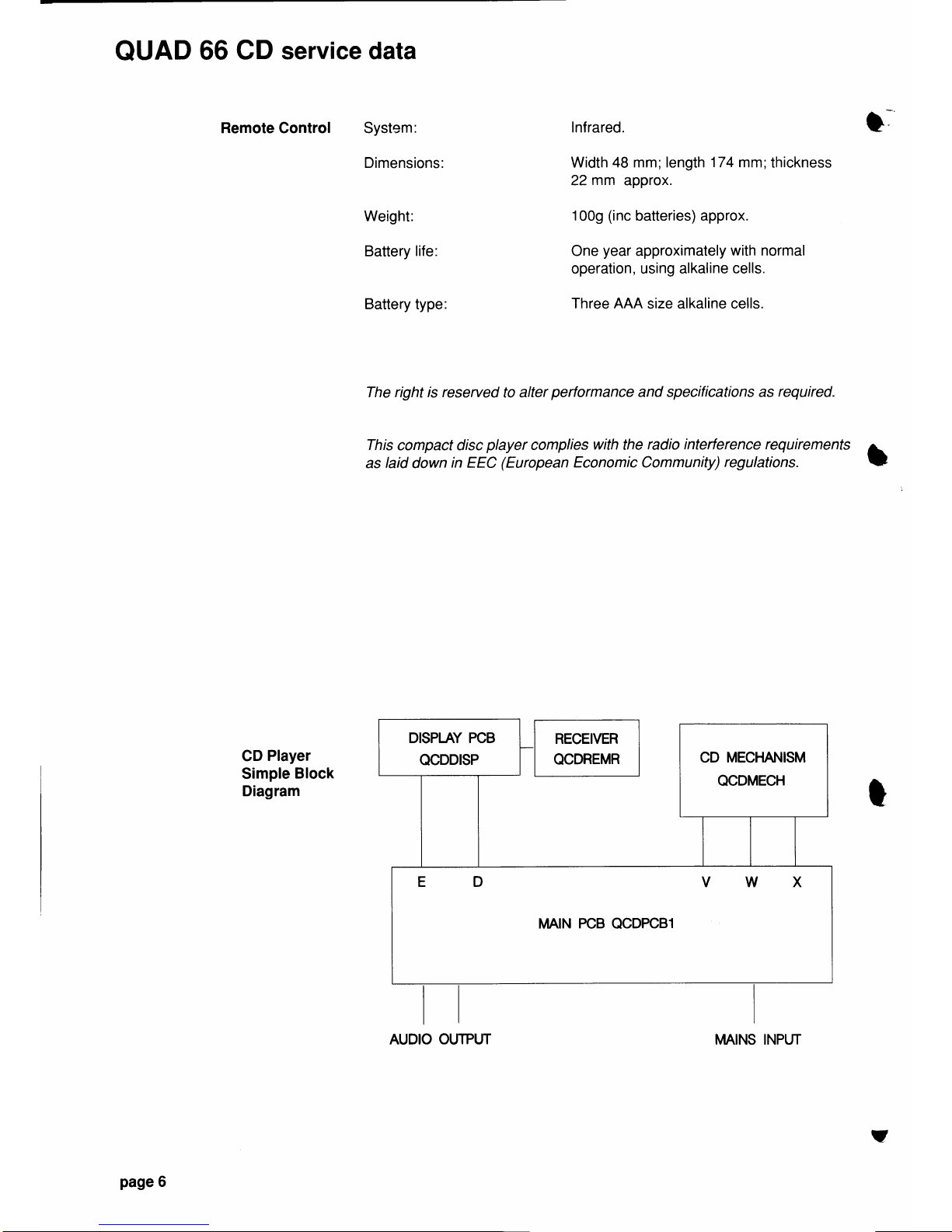
CD
Player
Simple
Block
Diagram
This
compact disc
player
complies
with
the
radio interterence requirements
A
as
taid
down
in EEC
(European
Economic Community)
regulations.
!
t
CD MECHANISM
QCDMECH
MAIN
PCB
QCDPCB1
page
6
AUDIO OUTPUT
MAINS INPUT
v
Page 6
*J
senvrcE
HINTS
Electrostatic Precautions
(ESD)
DISMANTLING FOR
SERVICE
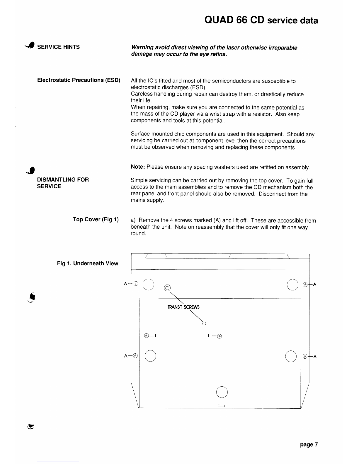
Top
Cover
(Fig
1)
Fig
1.
Underneath View
s
QUAD
66
CD service
data
Warning
avoid
direct viewing
of the
laser
otherwise irreparable
damage may
occur to the eye
retina.
All
the
lC's
fitted
and
most
of the
semiconductors
are susceptible
to
electrostatic
discharges
(ESD).
Careless handling
during
repair
can
destroy them,
or drastically reduce
their life.
when
repairing,
make
sure
you
are connected
to
the same
potential
as
the
mass
of
the CD
player
via
a
wrist
strap
with
a
resistor.
Also
keep
components
and
tools at this
potential.
Surface mounted
chip
components are used in
this equipment.
Should
any
servicing
be carried
out at component level
then
the correct
precautions
must
be observed when
removing
and
replacing
these
components.
Note:
Please
ensure
any spacing
washers
used
are
refitted
on assembly.
Simple
servicing
can
be carried out by removing
the top cover. To
gain
full
access
to the main
assemblies and to
remove
the
CD
mechanism
both
the
rear
panel
and
front
panel
should also
be
removed.
Disconnect
from
the
mains
supply.
a)
Remove
the
4
screws
marked
(A)
and
lift
off.
These
are
accessible from
beneath
the
unit.
Note
on
reassembly
that the cover
will
only fit
one way
round.
n-O
TRAI{$T
SCREWS
\o
@-r
L-@
'F
page
7
Page 7
QUAD
66
CD
service
data
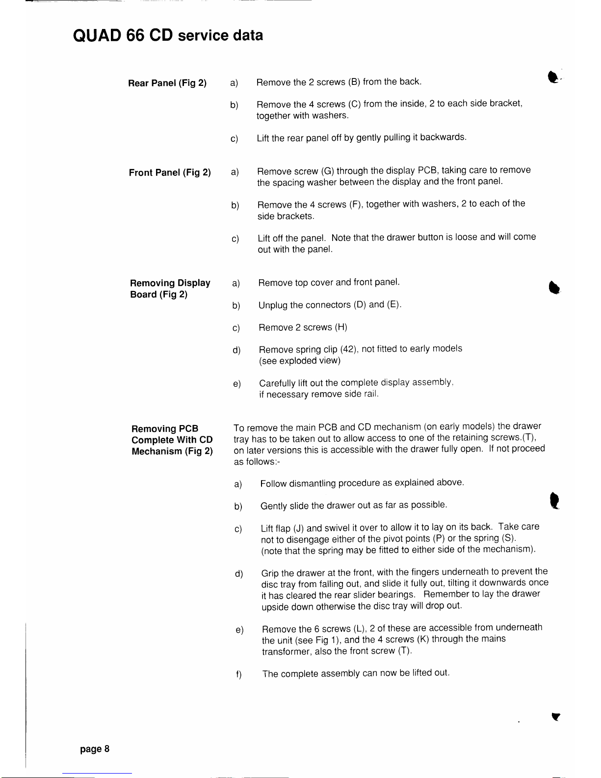
Rear
Panel
(Fig
2) a)
Remove the
2
screws
(B)
from the back.
t
'
b)
Remove the
4
screws
(C)
from the
inside
,
2lo each side
bracket,
together
with
washers.
c)
Lift
the
rear
panel
off
by
gently
pulling
it
backwards.
Front
panel
(Fig
2)
a)
Remove screw
(G)
through
the
display
PCB, taking
care
to
remove
the
spacing
washer
between
the
display
and
the
front
panel.
b)
Remove the
4 screws
(F),
together
with
washers,
2
to each
of the
side
brackets.
c)
Lift
off
the
panel.
Note that
the
drawer
button
is loose
and
will come
out
with the
Panel.
Removing
Display
a)
Remove top
cover
and
front
panel.
Board
(Fig
2)
b)
Unplug
the connectors
(D)
and
(E).
c)
Remove 2 screws
(H)
d)
Remove
spring
clip
(42),
not fitted to
early
models
(see
exPloded
view)
e)
Carefully
lift
out
the
complete
display
assembly,
if necessary
remove
side
ratl.
Removing
pCB
To remove the
main
PCB
and
CD
mechanism
(on
early
models) the
drawer
Complete
Witn
CO
tray
has
to
be taken
out
to
allow
access
to one
of
the
retaining
screws.(T),
Mechanism
(Fig
2)
on
later
versions this
is accessible
with the drawer
fully open.
lf not
proceed
as
follows:-
a)
Follow
dismantling
procedure
as
explained
above.
b)
Gently
slide
the
drawer
out
as
far
as
possible.
c)
Lift
flap
(J)
and
swivel
it over
to allow
it
to
lay
on
its back.
Take
care
not to disengage
either
of the
pivot
points
(P)
or the
spring
(S).
(note
that
the
spring
may be
fitted to either
side
of the
mechanism).
d)
Grip
the drawer
at
the
front,
with the
fingers
underneath
to
prevent
the
disc tray
from
falling
out,
and
slide
it fully out,
tilting
it downwards
once
it
has
cleared
the
rear slider
bearings.
Remember
to
lay the drawer
upside
down
otherwise
the disc
tray
will
drop
out'
e)
Remove the
6 screws
(L),
2
of
these
are
accessible
from underneath
the uinit
(see
Fig
1), and the
4
screws
(K)
through
the
mains
transformer,
also
the
front screw
(T)'
f)
The
complete
assembly
can
now be
lifted out.
t
t
page
8
?
Page 8

Fig
3.
Top View
(cover
removed)
QUAD
66 CD
service
data
s
J'
page
9
Page 9

QUAD
66
CD service
data
Replacing
CD First
remove
the
main PCB
assembly complete
as
shown
t
Mechansm
(Fig
3)
a)
Lary
iire
assembly upsicle
down and
remove
the
2
screws
(N).
b) Lift PCB
and carefully unplug the
flat
cable
(V)
and the 2
connectors
(W)
and
(X), (See
exploded
view).
Note: The
socket
(v)
is a lockable
type.
Lift
the outer
shroud
to
release
and
push
it
down to
lock.
c)
The
CD
mechanism
can
now
be
removed
and,
if necessary
replaced.
Should the
CD
mechanism
be
replaced it is important
that
the
focus
adjustment
and
laser
current are
set as shown
on
page
(12).
d) To replace
the
mechanism
secure
the CD
mechanism
to
the
main
PCB
with
the two screws
in
the
front
pillars
ensuring
any
spacing
washers
are
correctly
fitted.
Front
Fig
3. Underside
View
of
PCB
Note : When replacing
the CD
mechanism
ensure that the switch
link
assembly
is
correctly engaged. On
early
units the switch
rod
may
be
glued
to the
plastic
switch connector, to separate the switch
link mechanism
it may
be
necessary
to exert a twisting
pressure
between the
rod
and
connector.
On
later
models rubber
adjustment
rings
are
fitted
beneath
the
front
screws
on the CD
mechanism,
to allow accurate drawer alignment within
the
front
aperture.
l_
t.
?
a)
(
,1ri )
v
a)
^
.'"
ö
N..
oo
o
a)
\_-,/
a)
page
10
Page 10

t
To
Replace
Display
Bulbs
(Fig
4)
Fig 4. Display PCB
(underside
view)
Changing
Mains
Voltage
lmportant
Ensure rating
plate
shows correct
voltage.
These
are accessible
from
the underside of the display
PCB,
as
shown
below.
Turn
the
plastic
bulb cap approximately
114
turn anticlockwise,
to
release,
and
lift
out.
These
can be
quite
tight.
When refitting
please
ensure both bulbs
are turned
ll4turn
clockwise
to engage correctly.
The
Quad
CD
Player is normally
supplied
for 2201240V
ac operation. For
1 10/127V
operation the
mains
transformer can be set by
wire links
on the
main PCB,
the
mains input
power
fuse must
also be
replaced with
the
correct
rating. Facilities
are
provided
for
operation
from four
different
voltage ranges, 1 10V, 127V,220V
and
240V. However in
practice
the
127V
and
240V
settings
are
suitable
for most
applications but
for
'100V
supplies
(Japan)
the
1 10V
taps should be used.
a)
Remove main
PCB
assembly
as shown
in
'Dismantling
For
Service'.
b) Solder
links
as
shown
below and
fit
correctly
rated fuse:-
2201240V 160 mA
delay
part
number
UMA16DA
1101127V
315
mA
delay
part
number
UMA315D
QUAD
66
CD service
data
J
t
Front
v
pagel
1
Page 11

QUAD
66 CD
service
data
VOLTAGE MEASUREMENTS
AND
ADJUSTMENTS
Fig
5.
Adjustment
Points
Main
PCB
(top
view)
Warning
-
Direct
viewing
of the laser
to be
avoided.
a) Equipment
Required
1
. DVM
of at
least
ZO
kelV
.
2.
Hexagonal
trimming
tool for
adjusting
laser
current
and focus
offset.
3.
Philips
test disc
5.
b) DC Power
supplies
voltage
measurements
Reference
should
be
made
to the
circuit
diagrams
opposite.
All voltages
with respect
to
ground
0V.
c) Laser
Current Adjustment
(see
fig
5)
Using
track 1
of the
Philips
test
disc
5, adjust R3520
to
give
50 mV
DC
+107o
across
R3501
(TP1
and
TPZ).
d) Focus
Adjustment
(see
fig
5)
Using
track
1
of
Philips
test disc
5, adjust R3569
to
give
400mV
DC
t10%
between TP3
and
TP4.
This
now
completes
all the
Adjustments
necessary.
I
I
t
CHASSIS
OV
CONNECTION
Front
*(un
2^
üs
o
page
1 2
t
Page 12

QUAD
66 CD
service
data
{p
!
lc2 l
I
r00!
I
t-
RI
tct 63
56
58
21
lc7 542
59 61
60
6t 62
zRz
lc
T
22n
I
o, '*n,nrI
NC
NI-DISPLAY
-l-t
t-t t_t
rrllll
tl
-|-l
t-|-l
_|_t
t_|_l
l7 t8
R2
c3
2u?
I
|
.n
I
s60e
I
t-
I
sxi
R3
68K
TI
BC | 84K
CD
Display Circuit
Diagram
(2195
-
1.
CD)
?2
t--o-
a
a
!
-<,._
a?3
\_{L
?:a
aa
h,
P-
Power Supply Circuit
Diagram
(3104
-
108
-
6294
-
130 - 2)
page
1
3
Page 13

QUAD
66 CD service
data
I
e-
s--
113
114
116
117
118
119
121
F
q*
r--#-_
2:-
t22
-al
123
Component List
ref
item
101
Drawer
103
Cushion mount
104
Tray
105
Drive
belt
106
Pulley
107
Guide
pin
108
Cushion
(drawer)
109
Guide
pin
1 10 Tray
roller
1 1 1
Lever
112
Tray
spring
clty
1
7
1
1
1
1
1
1
2
1
1
ref
item
13
14
16
17
18
19
21
22
23
24
26
106
-
CD
Mechanism
Exploded View
Wl r
124
*y
blaJll
-ED
F
L
,za
qtv
CD
flap
1
Flap
spring
1
Roller
2
Bearing
1
Tension
disc 1
Spring
(mount)
4
Spring
guide
4
Spring(motor)
1
Tray
motor
1
Tray
lever
1
Tray
lever
spring
1
page
14
Page 14

Page 15

Page 16

-b
ORDERING
SPARE
PARTS To
allow
for modifications etc.
please quote
component
reference, value
and description
as
well
as the
part
number, when
ordering spares.
Also
product
model
and
serial
number.
MECHANICAL
PARTS
(EXPLODED
VIEW)
QUAD
66 CD
service data
.b
U
Ref Description
Qty
Part No.
1
2
3
4
5
6
7
I
9
10
11
12
13
14
15
16
17
18
19
20
21
22
23
24
25
26
27
28
29
30
31
32
33
34
35
36
37
38
39
40
41
42
CD
front
panel
assembly
Side bracket
Screw
M3xG mm
Sup
Pan
St
CD
Mains
switch
link
Drawer front
grey
CD
mains
connector
Fuse 2201240V 160
mA
delay
Fuse 1101127V
315
mA
delay
Rubber
adjustment
ring
Screw
M3x8 mm Sup
Pan
St
Bzp
Screw drive
4x10
mm AB
CD
player
mechanism
Screw
M3x45 mm Pos
Pan Hd Bzp
Belleville
copper
washer
Washer
684
Plated
St
Bzp
Mains
transformer
'1
1
0-240V
Mains
transformer CSA
version
120V
Cover assembly
(with
damping)
Flex
connector 3
way
Screw drive
4x10
mm
Csk
Pos
Flex
connector 6
way
Flex
connector
7 way
Rear
panel
(screened)
Solder tag
M3
Nut M3 Hex
St
Bzp
Shakeproof
washer
M3
St
Int
Main PCB
Plain rubber insert
for foot
CD chassis
Cover screw
M3x10
mm
sup
pan
Display
assemby
(complete
PCB)
Screw drive
4x6
mm
pan
black
Transit
screw
RH thread
(silver)
Transit
screw
LH
thread
(gold)
Screw drive 6AxG
mm
pan
black
Window mask
Bulbs
(backlit
display)
Window
(front
panel)
Drawer
open/close
button
Escutcheon
(open/close
Button)
Receiver
assembly
Receiver
retainer
(early
models)
Drawer
open/close
switch
Drawer
open/close
switch
inc PCB
Mains
on/off button
Clip
(switch
PCB
assy
to CD
mech.)
1
2
17
1
1
1
1
1
2
2
3
1
4
4
5
1
1
1
1
1
1
1
1
1
1
13
1
4t5
1
4
'1
2
2
2
2
1
2
1
1
1
1
1
1
1
1
'1
QCDFPAG
M221924
TM306PA
M215514
M21543G
M459934
UMA1 6DA
UMA31 5D
M20172M
TM3OSPA
TC41
OPF
QCDMECH
TM345PA
TD73206
TDB6NPA
LXCDEUR
LXCDCSA
Q66COVG
QCDCA83
TC41
OCB
QCDCAB6
QCDCABT
MCDRPSl
FTM331A
TM3FHPA
TDM3NLA
QCDPCBl
M20172A
M215054
TM31
OPA
QCDDISP
TC4O6PA
M221114
l\422111X
TC6O6PB
\4222914
BB515MB
MCDDWIP
M21 153C
MCDDW2S
QCDREMR
ATO503A
S44INPA
OCDPCBS
M2137
4A
FC0021 A
b
page
17
Page 17

QUAD
66 CD service
data
ACCESSORIES
MISCELLANEOUS
T
Ref
Description
Qty
Part
No.
--
1
2
3
4
5
6
Remote
control unit
(R1)
Battery
1.5V
AAA
size
Mains lead
(0.6m)
as supplied
Mains lead
(1
.5m) free
end
Signal
lead
Phono
(0.5m)
as supplied
Signal
lead
Phono
(1m)
1
3
1
1
1
1
QCDREMA
N1
VsAAA
QSPRSO6
QRS1
MsA
QP2P2SA
QP2P21A
Ref
Description
Qty
Part No.
1
2
3
4
5
Screw
kit
(inc
cover screws)
|
1
carton 66/CD
i
1
CD
Eperan
pack (Polystyrene)
I
1
Instruction
booklet
(English)
1
Service
manual
1
QCDSCR2
ZC6CDl
A
ZXCD1 AA
OICDl EC
OSCD1 EC
page
18
-
 Loading...