


INSTRUCTIONS FOR FITTING ADDITIONAL ANALOGUE
OUTPUT CARDS TO A MERIDIAN 861 (OA02,OA12)
1.2, 5/1/99
INTRODUCTION
The addition of an OA02 to an 861 allows for the connection of four configurable
standard analogue outputs. The addition of OA12 to an 861 allows for the connection
of four configurable balanced analogue outputs.
This sheet is intended as an installation guide for the fitting of these cards to a
Meridian 861.
To use either of these cards requires software version 2.0 or higher. You should use
the highest version of software available to you. To check your software, place the
861 in standby and press the Display key on the front panel. If it is lower than 2.0, you
will need to upgrade the software in the 861 using the discs included. Follow the
instructions for this in the Setup sheets before installing the card.
WARNINGS
1. The power cord must be disconnected when any casing is removed.
2. Static sensitive parts are revealed when fitting these modules.
TOOLS REQUIRED
No. 0 pozidrive screwdriver
3/16 inch flat blade screwdriver
JUMPER SETTINGS
The Analogue Output Cards can be configured for various combinations of speaker
outputs by setting jumpers. The positions for these jumpers are located near the 96way backplane connection on the card.
The card is factory set to Setting 1.
Setting 1: 1=Main Left,
2=Main Right,
3=Centre,
4= Mono/Centre/LFE Sub.
Page 1
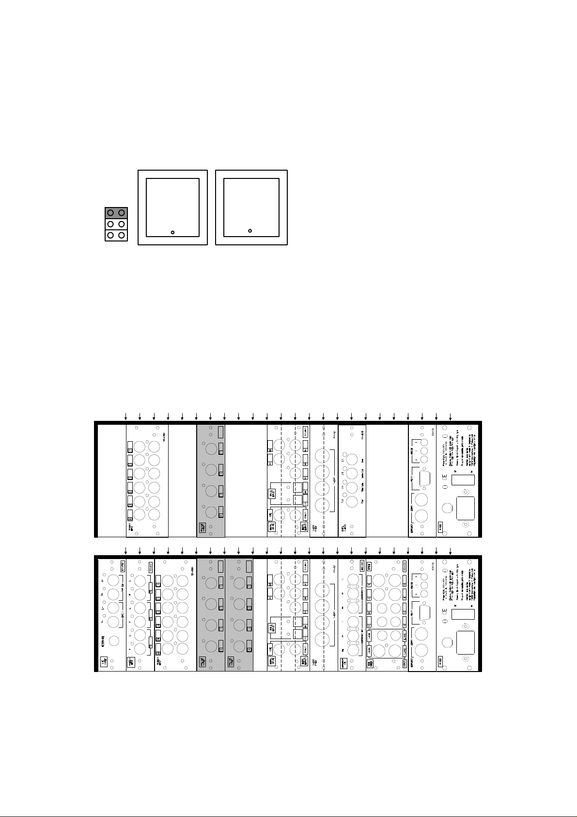
Alternatively, by fitting an additional jumper, it can be configured for Setting 2.
Setting 2: 1=Side Left/Surround Sub/Left Sub,
2=Side Right/Right Sub,
3=Rear Left,
4=Rear Right.
SITING
The diagrams below show four typical 861 installations.
Looking at the back of the 861. OA02 and OA12 should be fitted to the left of the
digital input card and to the right of the analogue input cards, if fitted.
Note: The digital input card, the computer card and the DSP cards should not be
removed and re-sited.
J2 J21 J22
J1
J3 J4 J5 J6 J7 J8 J9 J10 J11
J2 J21 J22
J1
J3 J4 J5 J6 J7 J8 J9 J10 J11
J12
J13 J14
AB00 Z300
J12
J13 J14
AB00 Z300
J15
J15
J16
J16
J17
J17
J18 J19
J18 J19
J20 J23
J20 J23
J24
J24
Page 2

Input
Analogue
J2 J21 J22
J1
J3 J4 J5 J6 J7 J8 J9 J10 J11
J2 J21 J22
J1
J3 J4 J5 J6 J7 J8 J9 J10 J11
J12
J13 J14
AB00 Z300
J12
J13 J14
AB00 Z300
J15
J15
J16
J16
J17
J17
J18 J19
J18 J19
J20 J23
J20 J23
J24
J24
INSTALLATION PROCEDURE
Note: Observe static precautions throughout the installation period.
1. Switch off the unit and remove the power cord.
2. Remove blanking panels as required using a No. 0 pozidrive screwdriver. Retain
panel and fixings.
3. Slide the new card into its intended guide rails (see diagrams above). Ensure
correct card orientation (component side of OA02/OA12 leftmost when viewed
from the rear).
4. Check the card is aligned correctly and slides freely down the card guides.
5. Push the car gently until its panel is flush with the rear panel. If the cards are
aligned correctly in the card guides then only slight force will be required to mate
the connectors.
6. Gently tighten the rear fixings using the flat blade screwdriver. Do not over
tighten.
7. Connect up the new analogue outputs.
8. Re-connect the power cord and switch on.
SETTING UP OUTPUTS
Outputs are automatically configured by selecting different options in the Speakers
section of the setup program. Open a file in the program, then go to 861 Surround
Controller, then Current Settings, then Speakers. Check that the speakers you wish
to connect to the Analogue Card are set as Analogue. Calibration of the outputs can
then be performed in Calibration in the 861, See the 861 User Guide for details.
Page 3
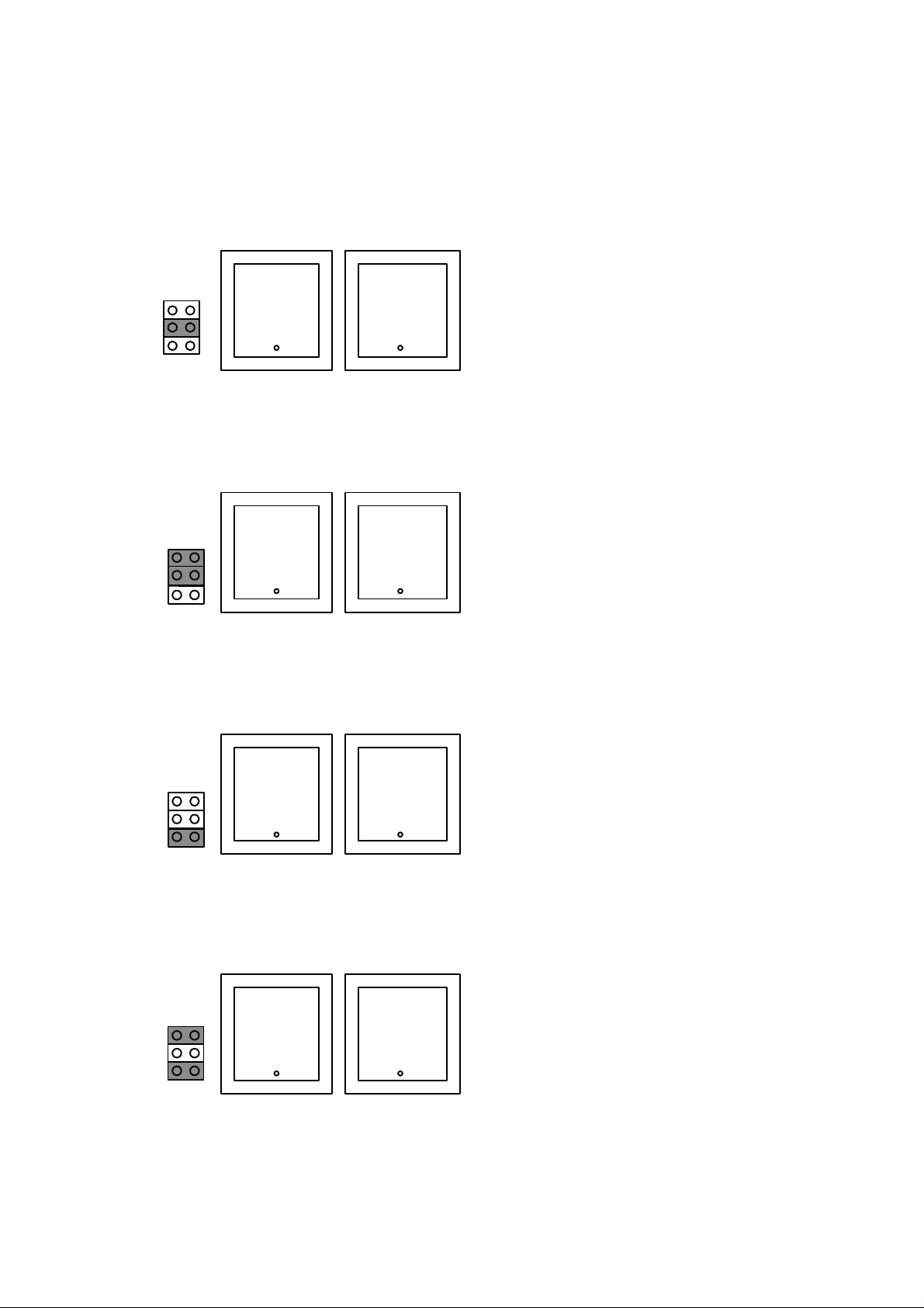
ADVANCED OPTIONS
Setting 3: 1=Centre
2=Mono/Centre/LFE Sub
3=Rear Left
4=Rear Right
Setting 4: 1=Main Left
2=Main Right
3=Side Left/Surround Sub/Left Sub
4=Side Right/Right Sub
Setting 5: 1=Main Left
2=Main Right
3=Rear Left
4=Rear Right
Setting 6: 1=Centre
2=Mono/Centre/LFE Sub
3=Side Left/Surround Sub/Left Sub
4=Side Right/Right Sub
Page 4
 Loading...