

Page 1
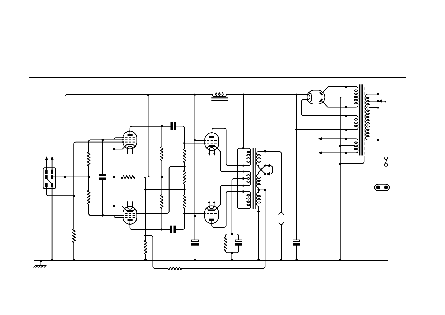
QUAD II Power Amplifier
R
C
HT and
heaters to
Control unit
socket
SK
1
h h
4
2
56
3
1
Input
R
1
1.5MΩ
1
R
1MΩ
R
1MΩ
2
3
2
3
1
110V 0.22mA
C
1
0.1µF
110V
0.22mA
V
EF86
2.2V
V
EF86
4
1
h h
R
680Ω
h h
2
1.2mA
4
115V
1.2mA
R
100Ω
115V
10
10
R
180kΩ
R
6
180kΩ
11
7
8
9
12
5
6
2
6543
T
V
5
SK
SK
C
16µF
450V
GZ32
C6 and C4 are in the
2
large square can. C
plain foil) and has
3
rating, C4 is marked
6
+E (for etched foil)
and is more like a
standard electrolytic
h
h
is marked +P (for
the higher ripple
capacitor
330V
17mA
L
h h
h h
65mA
65mA
R
12
180Ω
3W
1
For 15Ω speakers link S to
R as shown, for 8Ω link S
Y
Z
U
26V
V
W
X
C
25µF
50V
C
2
0.1µF
350V
5
680kΩ
2.7kΩ
680kΩ
C
0.1µF
350V
R
7
R
8
R
9
3
C
16µF
450V
14mA
V
3
KT66
V
4
KT66
4
147mA
to T and Q toR
T
1
5
340V
T
S
R
Q
Output
310V
rms
310V
rms
5V rms
6.3V rms
HT
HT
5V
5V
6.3V
6.3V
E
Note: The original capacitors for C
6
which were connected to ground, the
small capacitance to ground controls
the open loop frequency response and
change these capacitors with caution!
2
240V or 130V
220V or 115V
200V or 100V
com
F
1
2A 200-250V
3A 100-130V
PL
1
a.c. mains from QUAD 22
control unit
and C3 had insulated metal bodies
thus the stability with feedback;
2
R
470Ω
11
QUAD II Power Amplifier Schematic Drawing 11175 iss.1 Redrawn in original style by
Keith Snook
d.c.~daylight ltd.
1994
 Loading...