

Page 1

PDF Cover Page
♦ ♦
Hand-Builders of Fine Music-Reproduction Equipment
❦
Precision Electro-Acoustic Research Laboratory.
No. 200, 2137 33 Ave. SW; Calgary, AB; T2T 4X3
Ph: +.1.403.244.4434 Fx: +.1.403.244.9026
Web:
http://www.pearl-hifi.com
E-mail:
custserv@pearl-hifi.com
This document has been prepared as a public service and
is intended for unrestricted distrubution.
Any and all trademarks and logotypes used herein are
the property of their owners.
Please note that the links in the PEARL logotype above are “live”
and can be used to direct your web browser to our site or to
open an e-mail message window addressed to ourselves.
Page 2
General
The notes in this section are for the guidance of the engineer who has so me experience of ca rrying out repairs to
these speakers together with the necessary proper materials for the repair.
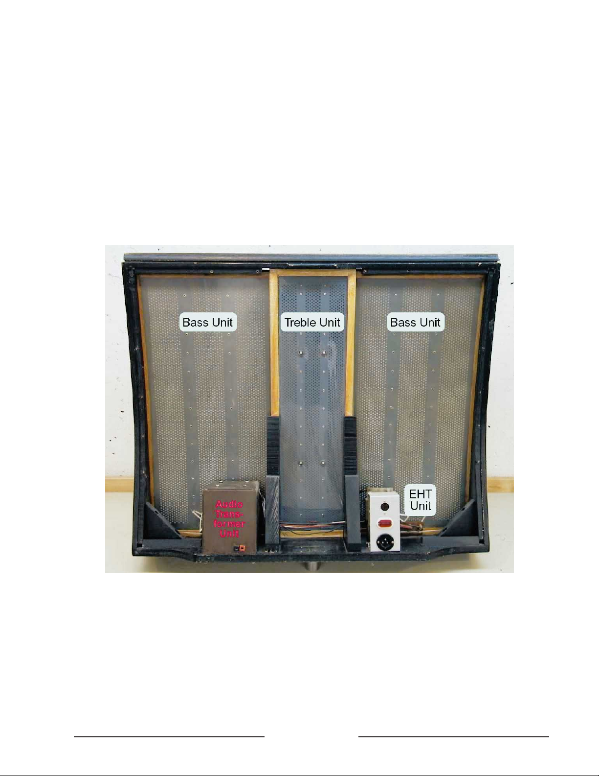
The QUAD electrostatic speaker consists of five components: two bass units, one treble unit, an audio transfo rmer
uni t a nd an EHT supp l y unit. I f a ny repa i r s a re necessa ry, it should be ascerta ined whi ch o f t h e five compone n t s i s t h e
cause and that component should be either replaced complete or repaired as appropriate.
Fault Diagnosis
Loss of Sensitivity
Check the EHT voltage, which should be: Bass 6Kv + 7%; Treble 1.5Kv + 7%.
If low, check, by disconnecting, whether due to leakage in speaker unit or fault within EHT unit. Voltages must be
checked only with electrostatic meters, as the current drawn by other types may itself damage the rectifiers.
Distortion
1. Make sure that the speaker is really at fault by comparison with a second electrostatic speaker, using a QUAD
amplifier.
2. Check EHT voltage.
G
Page 1
G
Quad Electrostatic Loudspeaker
Service Data–Model ESL 57
Page 3

3. Suspect intermittent breakdown in speaker units.
4. Suspect intermittent breakdown in audio transformer unit. (Note: a fault in this unit is very unlikely).
No Output at All
Suspec t EHT unit or audio transformer unit af ter checking more ob vious things like external connections, not for-
getting the leads under the transformer unit connecting the input sockets.
Background Noise
One cause of background noise in the electrostatic loudspeaker is internal discharge of the EHT supply at times
of high humidity, or high voltage, or both. This may be reduced by lowering the EHT voltage and a tap is p rovide d on
the EHT mains transformer for this purpose.
Befo r e t he EH T u n it i s to uch ed th e m ai ns s ho u ld be co mpl et e l y dis con n ected a nd t he l ou dspe ak er l e ft to st a nd f o r
two hours to ensure it is completely discharged.
The connectio n s to the EHT rectifier block are normally take n from tags mark ed C ommon and 61 0V. The l a tt er is
the righthand end tag and next to it is a blank tag marked 590V to which should be transferred the lead normally connected to the 61 0V tag. Background noise may also be caused by discharge of the EHT from points external to the
loudspeaker units, at the tags on the rectifier block for example, if a hair of felt or piece of fluff comes in reasonably
close proximity to that point, or if a spike of solder or sharp point of wire permits corona discharge.
Where EHT leakage occurs via a bass unit, this is sometimes found to be discharging from one of the eyelets
around the periphery of the bass unit plates, probably to one of the aluminium brackets. In such cases a satisfactory
repair can b e effec ted by slitting the polythene tape round the ed ges of the unit, opening the dustc over frames and
insulating the leak by applying a single layer of similar polythene tape all round the periphery of the internal plates, on
top of the existing sealing tape, and reassembling the dustcovers, again with polythene tape.
Other internal failures of insulation will probably necessitate replacing the loudspeaker unit affected.
Mechanical
If the dust seal covers should be torn, it may be necessary to replace the complete unit as there will have been
ingress of dust, which causes loss of sensitivity of the unit concerned.
Dismantling the Speaker
The loudspeaker should be switched off for about two hours before the grilles are removed, so as to ensure the
EHT unit has completely discharged.
The component loudspeaker units of the QUAD electrostatic loudspeaker must be handled with the utmost care,
partly because when not supported by the rigid frame of the cabinet they are more liable to physical distortion which
wou l d reduce th e small intern al clearances, and pa rtly becau se the dus t covers are necessarily made of v ery thin and
therefore fragile plastic film.
At the rear of the tre ble unit are four pins lo c ate d in the woo den str uts of the c abinet, and as these rep resent an
additional hazard to the dust covers of the treble unit, the positioning of this unit requires particular care.
Soldered joints should be smoothed and rounded and all spikes of solder, wisps of wire, etc., removed as these
would tend to cause arcing at the high internal voltages used.
Removing Front and Rear Expanded Metal Grilles
The rear grille is held only by the screws around its periphery. For the front grille it is necessary first to remove the
side mouldings, the staples through the metal beneath them, and the screws under the baseboard.Then the bottom
edge of the grille is lifted gently outwards and upwards until the top rear edge may be slipped out of its groove in the
cabinet, when the whole grille will be free. Care must be taken not to strain the top curved section during removal or
the metal may split.
Replacing the Front Grille
Replacement grilles are normally supplied cut and partly preformed so the procedure is as for refitting an existing
grille . I t m ay be fou n d h e lpf ul when w o rking sing l e h a n ded, having ins ert ed t h e t o p ba ck edg e o f t h e s h ee t i n t o t h e s lo t
in the cabinet, to hold the bottom edge of the grille under slight tension to the bottom of the wooden frame by means
of elastic ban ds and simp le hooks of w ire, such as an o pened paper clip, a n d then to use a bar of wo od slightly lon ger
than the width of the sheet, and with a good flat face, to bed the grille to the frame by moving the bar progressively
down t he face of t h e g ri l l e, tacki n g th e s ide s a s y o u go, final ly securi n g t he bo tto m edg e wi t h t h e scr e ws r e m o v ed f r o m
the old grille. Do not forget to fasten the earthing lead to the grille.
G
Page 2
G
Page 4

Replacing Bass and Treble Units
1. Remove both grilles.
2. Remove the top and bottom aluminium brackets in front of the centre (treble) unit.
3. If the treble unit is to be replaced, it should now be disc onnec te d from the audio transformer (the large rectan gul ar can on the left-han d s i d e when vie wed from the re ar). This is held in posi t ion solely by f our screws whos e h eads
are accessible below the baseboard of the speaker. If the speaker is tilted to provide access to slacken these screws
it must be restored to its upright position before they ar e remo ved or the tra nsfo rmer will hav e no support other than its
connecting wires.
4. Car efully prise out one bass unit and slide it past the front of the treble unit until the outer edge clears the remaining bracket at top and bottom of the cabinet.
5. E i ther disco nnect and remove the bass unit if t his has to be replaced o r m o ve it far enough to enable access to
be obtained to the treble unit, as required. To remove the tr eble unit ensure it is free of the four pins mentioned on page
2, then slide it sideways.into the space vacated by the bass unit already moved, and lift it out.
EHT and Audio Transformer Units
Only the rear grille need be removed to provide access to these units. Both are secured by screws through the
base board only and if the s peaker is tilted to ob tain acc ess to these sc rewheads it must be restored to the upr ight
position before the screws are removed or the unit will have no support other than its connecting wires.
Place a sheet of cardboard behind the unit to be worked on to protect the thin plastic dustcover of the bass unit
from accidental damage due to specks of solder or wire ends, etc.
Note and mark the flexible connections to the unit to be worked on so as to ensure correct reconnection.
To replace the rectifier block of the EHT unit, undo the two 4BA nuts securing it to the framework of the EHT unit
and remove it. If the replacement block is found to be of a different type, it will still be electrically and physically interchangeable with the earlier type, and the equivalent connections are shown in Fig. 1. If the leads to the loudspeaker
units have to be extended, the joints should be insulated with high voltage sleeving and staggered so that two joints
do not lie together.
To remove the Audio Transfo rmer , after having removed the four securing screws, inve rt the transfo rmer and unsolder the wires.
Reassembling the Speaker
To reasse mb le, the d ismantlin g procedure is reversed, but in addition it will be necessary to remove any wrinkles
which may have appeared in the treble unit's front and rear dust covers, as these will produce audible rattles when the
speaker is in use. This is achieved by means of gentle heat which thermosets the plastic film, and may most conveniently be applied by means of a small warm air blower, such as a hand-held dryer. The nozzle should be held about
G
Page 3
G
6kV
to Bass Units
1.5kV to
L
E
New-type
Block
Treble Units
AC from
Transformer
No External
Connection
Fig. 1
Old-type
Block
L
E
As viewed from the
rear of the speaker
with the grille
removed.
Page 5

25mm from the dust cover and moved up and down the unit as uniformly as possible at a speed of about 75mm per
second , i n r eg ular lines so as t o co v e r t he w h o l e a r e a . R epe at u n t i l a l l w r i n kl e s have dis appe a r ed, but al ways treat th e
whole area and do not tackle individual wrinkles separately . A certain amount of skill is required in this operation. Obviously if the n ozzle is no t cl ose enou gh and/or t he speed of trave l too gre a t, there will n ot be enough heat to affect the
cover. On the other hand too much heat at one point can quickly burn a hole. When carrying out this process for the
first time, progressively reduce the distance and speed until the desired results are obtained.
Heat should not be applied to the bass unit covers. An y slight wrinkles in these covers will r ar el y hav e any a udible
effect and will in any case normally disappear as the tensions even themselves out in a few days.
After t he rmos etti ng th e tr ebl e u nit d ust co ve rs , th e dam pi ng f elt s beh ind t he t reb le u ni t mu st be st re tched a nd fix ed
so that there is no contact between them and the treble dust cover, as this will also affect reproduction.
Fitting New Dust Covers
Note: T he plate s a n d d u s t cover material a cquire a s t a t i c ch arge and i f p l aced in a dusty a tmosphe re or near any
accumulation of dust it will adhere to them, with deleterious effects. Only plastic film supplied by Acoustical should be
used. Specify whether for bass or treble unit when ordering.
First remove the faulty unit from speaker as described on page 2 and strip the adhesive tape from around its
edges to r el eas e th e two dus tcov er f r am es . On ba ss un its , ca re fu ll y di scon nect th e th re e wi re s fr om t he t ermi na l boa rd ,
having noted their positions, and remove the board. Clean all loose dustcover material from the wooden frames since
any pieces left to flap will buzz.
If th e bass o r tr eble u ni t is to be l eft wi tho ut du stco ve rs fo r an y l engt h of t im e , it sh ou ld be kep t in a du st f ree e nv ir on men t.
Spread enough of the new dust cover material on to any clean, solid, flat surface to leave about 150 mm surplus all
around the frame, and hold in position with pieces of adhesive tape at each corner and at intervals along the sides as required.
The materials should not be over stretched but just tightly enough to remove the wrinkles.
Adhesive can now be applied to the frame , the frame placed in to po sit io n on t he m ate ria l a nd le ft to d ry. The adh esive should preferably be of a t ype which does not se t brit tle, such as Samual Jones' Samson C 20 3, Evostick, etc.
When t h i s is d ry, use a r azor bla de t o t ri m o ff a l l s u rpl u s co v e r ma te ri a l b ack t o t h e edge o f t h e f rame. The h ol e s to t h e
termi n al s sho u ld be BU R N T t hr ou gh t he fil m wi th a s ma l l sol der in g ir on . I f pi er ced col d th e mat eri a l wi ll i n t im e spl it a nd
run the whole length of the dust cover.
When a pair of covers have been made, the unit and the covers should be blown with a jet of dr y air to remove
any dust particles etc., which have adhered to them, as this will cause a loss in sensitivity.
GREAT care should be taken if it is found necessary to renew any soldered joints on the plates. Anything more
than a quick touch to the tags will soften the plate material and loosen the solder tag. A heat sink is helpful here.
When r eco nn ecti ng to t he te rmi na ls be su r e no t to cro ss wi r es as t hi s wi ll r es ul t in t he f a il ur e o f the spe ak er t o wo rk.
The unit should be replaced between the two frames and sealed with 50mm wide polythene adhesive tape all
around the outside edge of the frames as before.
This completes the recovering and the unit can now be reassembled into position in the speaker.
Modificati o ns
1. At serial number 16800 (March 1966) additional filtering was added to protect the treble unit from damage due
to high level low frequency signals. Earlier speakers may be modified as described below, when they are to be used
with the Quad 303 or other suitable amplifiers of comparable output.
The components required can be obtained ready assembled on a tagboard, if required, and Fig.2 shows this in
position under the audio transformer . Alternativel y, suitable resistors and capacitors from normal servicing stocks, may
be used if preferred.
Fig. 3 shows the tagboard layout from serial number 16800 onwards.
Modificat ion procedure for loudspeakers earlier than seri al numbe r 16800 when used wi th the Quad 303 amplifier .
(a) Remove the AC supply from the speaker and allow two hours for the EHT to discharge.
(b) Undo the screws all around the periphery of the rear grille and remove the grille.
(c) Til t th e lou dspea k er to pe rmi t acce ss to t he u nde rsi de o f th e bas eboa rd , t aki ng ca re n ot t o den t t he f ro n t gri l le.
(d) Remove the four screws holding the audio transformer (large can on the lef t hand sid e ) in plac e, remember-
ing to support
the transformer before it is freed or it may slip and damage the left hand bass unit dustcover.
(e) Rest ore t he spe ake r to an up righ t posit ion a nd in vert t he a udio transformer , taking care not to strain its external wiring.
(f) Remove the two drive screws on the right hand side of the tagboard and use these to secure the small tag-
G
Page 4
G
Page 6

board supplied,
as shown in fig. 2.
(g) Rewi re a s sho wn , ensu ri ng th at the b row n lea d wh ich has t o be str etch ed to re ach it s new a nchor po int do es no t pre ss
against any sharp edges of turret lugs or solder.
(h) Reassemble the speaker in the reverse order of operations (a) to (e).
2. Voltage selector and voltage selector socket changed.
Old types no longer available. New type Stock No's. SelectorSV5049A. Select. skt. SVB9AAA.
The two types are not interchangeable.
3. At Serial No. 44000 the A.C. supply voltage plug and socket changed.
Stock No's. ESL up to Serial No. 44000, plug - PP1403A, socket- PS18621.
Stock No's. ESL after Serial No. 44,000, plug - PPP579A, socket- PSP587A.
4. At Serial No. 45590 supply indicator neon changed.
Stock No's. ESL up to Serial No. 45590- BNSL50R.
Stock No's. ESL after Serial No. 45590- BNT430R.
The two types are not interchangeable.
G
Page 5
G
Brown wire from front of treble plate
12345
2 x 560pF
Erie
K1200/CD7
270K
Erie
Type 8
678910
11 12 13 14 15
16
Fig. 3 Fig. 2
Page 7

G
Page 6
G
COMPONENTS LIST
Components and circuit detail may vary sli ghtly
dependi ng o n th e a ge o f th e equ ip me nt . In ca se o f do ubt
please refer the query to Acoustical.
Assembly Oelsprs E/Speaker components list
Part No. Description
BNSL50R Neon SL50 Red
BNT430R Neon Type T430 Red
PP1403A Plug 3 pin AC SA1403
PP579A Plug 3 pin AC Euro
PP378A0 Plug L378A 4 Black 4mm
PP378A2 Plug L378A 4 Red 4mm
PS13180 Socket 4mm L1318 Black panel
PS 13182 Socket 4 mm L 1318 Red panel
PS18621 Cable end skt 3 pin AC
PSP587A Skt P587 AC cable
QELBAPA Quad ESL bass unit
QELCONA ESL mod. kit
QELES1 B ESL aluminium bracket
QELFGPK ESLfrontgrille-Black
QELFGPZ ESLfrontgrille-Bronze
QELHTPA ESL EHT unit
QELHTPC ESL EHT unit - Canada
QELHTPS ESL EHT unit - Sweden
QELHTTD EHT unit Demko
QELLAPA ESL audio transf.
QELLEGA ESL legs set
QELLMPA ESL AC supply transf.
QELREPA ESL rectifier block
QELRGPA ESLreargrille
QELSIPA ESL side rails
QELTRPA ESLtrebleunit
SV5049A Voltage selector T5049
SVB9AAA Voltage selector skt
EFMY06A Treble unit dustcover material
M11078A Treble unit dustcover frame
EFSA50A Bass unit dustcover ma terial
M11079A Bass unit dustcover frame
I BELBAA Bass unit terminal board
FP2630A Bass unit terminal
C560PMI Capacitor 560pF
R150KKA Resistor150K10%Type 8
R180KJB Resisto r180K5%Type 8
R270KKA Resistor 270K 10% Type 8
IP1401 B Polythene tape 50mm
Use on ESL up to
Serial No.44000
Use on ESL after Serial
No.44000
Round AC input connector use on ESL up to Serial
No's.44000 Use on ESL Serial No.44000 and over
Fit to speakers Serial No.16800 and below when
used with amplifiers of greater output than the Quad II
 Loading...