

Page 1

R E V.1
C O N C O U R S E C S E R I E S
INSTRUCTION BOOKLET
MODELS C4, C4-16, C4-T, C6, C8, & CSUB
F O R T H E C L O S E S T A P P R O A C H T O T H E O R I G I N A L S O U N D
Page 2

TA BLE OF CONTENTS
Introduction:
Safety Instructions ....................................................................... 02
Warnings & Disclaimers .............................................................. 02
Rigging & Suspension ................................................................. 02
Warranty & Service .................................................................... 02
Product Descriptions:
C4, C4-16, C4-T, C6, C8, & CSUB .............................................. 03
SAF ETY INST RUCTIONS
Safety First!
1. Please read this manual fully before installing and operating this
product.
2. Retain a copy of this manual for future reference.
3. Comply with all warning labels and instructions.
4. Do not attempt the installation of this equipment unless you are
qualified to do so.
Product Features:
Product Diagram ........................................................................ 04
Components ............................................................................... 05
Dimension Drawings ................................................................... 06
Installation - Suspended Tile Ceilings:
Installation Instructions ................................................................. 07
Installation - Hard Ceilings:
Installation Instructions ................................................................. 09
Connections:
Input Connectors ......................................................................... 11
Number of Speakers Calculation .................................................. 11
Reccomended Wiring Scheme ...................................................... 11
CE Compliance:
Statement ................................................................................... 12
Product Specifications
Specifications ............................................................................. 13
Contact Information:
QUAD Industrial Contact Information ............................BACK COVER
5. Protect your hearing from high sound pressure levels.
Rigging and Suspension
The rigging, suspension or mounting of these products can expose the
installer and members of the public to serious health risks and even death.
UNDER NO CIRCUMSTANCES ATTEMPT TO RIG, SUSPEND
OR OTHERWISE MOUNT THIS EQUIPMENT UNLESS YOU ARE
FULLY QUALIFIED AND CERTIFIED TO DO SO BY RELEVANT
LOCAL, STATE AND NATIONAL AUTHORITIES. ALL RELEVANT
SAFETY REGULATIONS MUST BE FOLLOWED. IF YOU ARE NOT
PROPERLY QUALIFIED OR DO NOT KNOW OF PERTINENT
REGULATIONS, CONSULT QUALIFIED PERSONNEL FOR ADVICE
AND ASSISTANCE.
Limited Liability
QUAD Industrial assumes no liability whatsoever for any damage or loss,
either direct or consequential arising from the installation and use of these
products. Liability is limited to replacement of product or refund, at the
QUAD Industrial’s discretion. Your rights to compensation may vary by ter
ritory; consult with your local QUAD Industrial office or distributor.
-
Warranty & Service
These products are designed to be used as specified, and are warranted to
be free from defects in materials or workmanship. Warranty terms and con
ditions vary by territory. Please contact your local QUAD Industrial sales
office or distributor for complete details. Under no circumstances should
you attempt to repair these products. Doing so may limit or void warranty
coverage.
-
2
Page 3

PRO DU CT D ES CR IPTION
The Concourse C series are two-way, high performance ceiling
mounted speaker systems designed for distributed music, paging
and speech applications. Packaged in pairs (except the C-SUB
and C-SUBT) and including all needed mounting accessories, the
C series models are complete vented speaker assemblies with a
metal back box, ABS front baffle and attractive metal grille. Each
model is available in both low-impedance 16Ω and constant-voltage 70/100V versions (with T suffix).
CON CO UR SE C 4/ C4-16/C4T
The Concourse C4 is a two-way ceiling mounted speaker system
consisting of a 4" cone low frequency driver and a 1" soft dome
tweeter. Speakers are packed in pairs and come complete with a
tile backing C-ring, mounting support rails plastic paint covers and
cardboard cutout templates. There are three versions available:
• Concourse C4 –
operation, 30W transformer included
Selectable 4Ω/16Ω/70V/100V
Concourse C8
The Concourse C8 is a two-way ceiling mounted speaker system
consisting of an 8" dual voice coil cone low frequency driver and
a 1" soft dome tweeter. Speakers are packed in pairs and come
complete with a tile backing C-ring, mounting support rails, plastic
paint covers and cardboard cutout templates.
• Concourse C8 –
operation, 60W transformer included
Selectable 4Ω/16Ω/70V/100V
Concourse CSUB
The Concourse CSUB is a ceiling mounted subwoofer system consisting of a 10" sub bass driver and integral low-pass crossover.
The CSUB is fitted with dual low-impedance voice coils allowing
connection to stereo power amplifiers at either 4Ω or 16Ω, or to
70/100V amplifiers through a built-in 100W transformer.
• Concourse CSUB –
operation, dual 50W low impedance coils, 100W
transformer included
Selectable 4Ω/16Ω/70V/100V
• Concourse C4-16 –
• Concourse C4T –
30W transformer included
16Ω version, 25 Watts
70/100 Volt operation only,
Concourse C6
The Concourse C6 is a two-way ceiling mounted speaker system
consisting of a 6" cone low frequency driver and a 1" soft dome
tweeter. Speakers are packed in pairs and come complete with a
tile backing C-ring, mounting support rails plastic paint covers and
cardboard cutout templates.
• Concourse C6 –
operation, 50W transformer included
Selectable 4Ω/16Ω/70V/100V
3
Page 4
PRO DU CT F EATURES
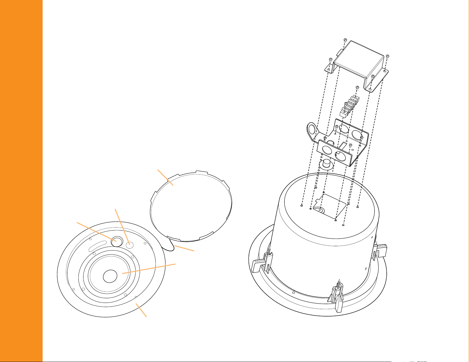
All models include the following components:
• Speaker assembly (2)
• Cover grille with restraint (2)
• Split C ring backing plate (2)
• Support Rails (4)
• Plastic paint cover (2)
• Cardboard cutout template (2)
Please ensure that you are familiar with all of the parts and how
they are assembled before commencing the installation.
GRILLE
POWER TAP SWITCH
HF DRIVER
GRILLE TETHER
LF DRIVER
BEZEL
4
Page 5
PRO DU CT D ES CR IPTION
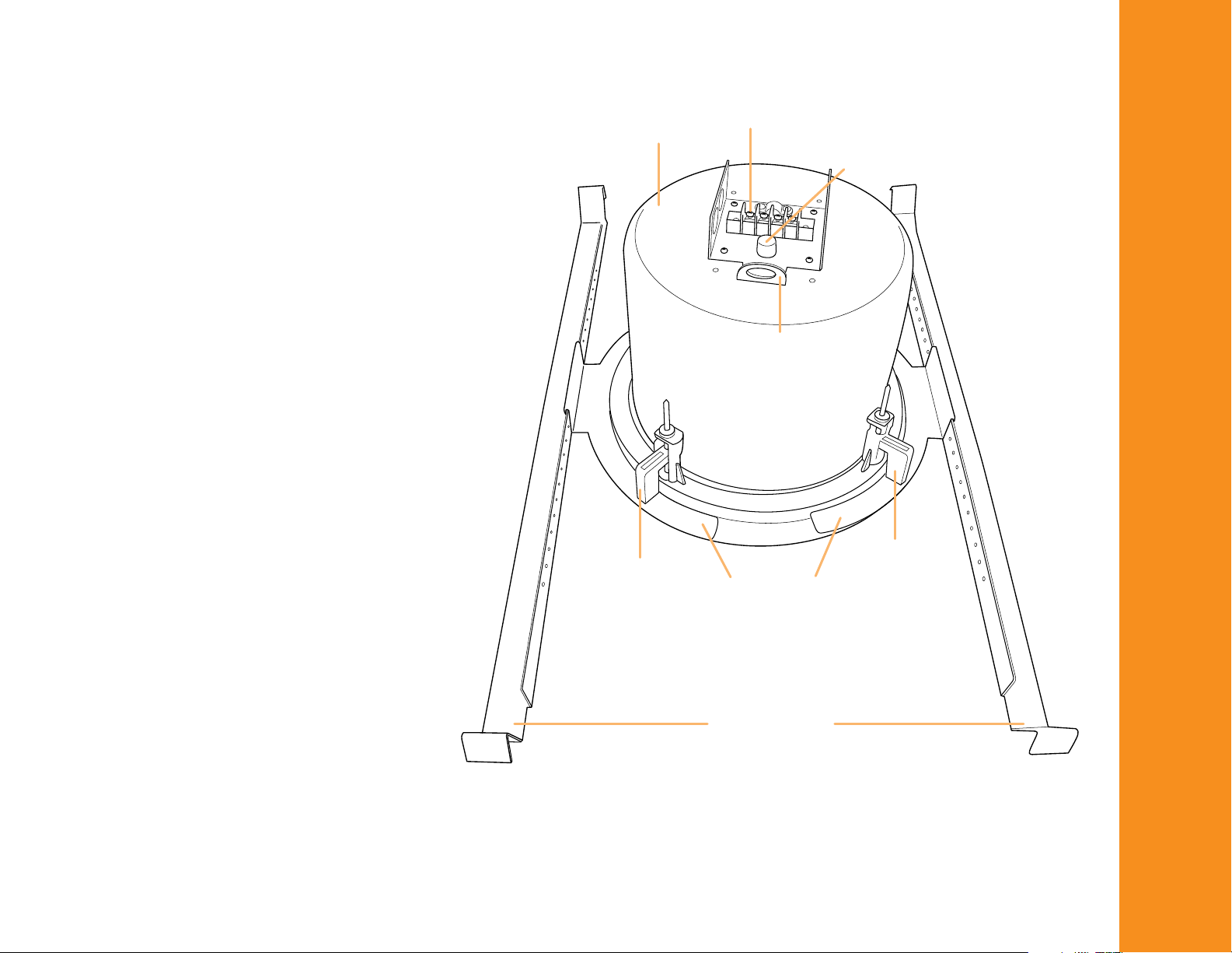
Concourse C models are complete assemblies
ready for installation into both suspended tile
ceilings and hard ceilings. A rear mounted terminal box allows termination of the speaker wiring
to the speaker as well as impedance selection
(except C4T and C4-16). Power taps are selected
on 70/100V versions through a front mounted
rotary switch.
Speakers are mounted by means of four mounting
clamps located around the rear face of the bezel.
A metal split C ring is provided to distribute the
clamping pressure evenly along the ceiling surface. A pair of metal mounting support rails are
provided for added support when the speakers
are installed in a suspended tile ceiling.
A seismic restraint point is provided on the rear of
the speaker to facilitate attachment of a restraint
tether to the building’s structure. The removable
front grille is also fitted with a restraint tether that
attaches to the inside of the bezel by means of a
supplied insert.
BACKBOX
MOUNTING
CLAMPS
INPUT TERMINALS
IMPEDANCE SELECT SWITCH
SEISMIC
RESTRAINT
POINT
MOUNTING
CLAMPS
SPLIT C RING
SUPPORT RAILS
5
Page 6

Concourse C4, C4-8, C4-16, C4-T
Concourse C6
Concourse C8
Concourse CSUB
219mm/8.62”
219mm/8.62”
349mm/13.74”
331mm/13.03”
371mm/14.6”
238mm/9.37”
293mm/11.54”
333mm/13.11”
212mm/8.35”
252mm/9.92”
212mm/10.04”
295mm/11.61”
6
Page 7

INS TALLAT IO N
Sus pe nd ed T il e Ceilings
Step 1
Carefully unpack the contents of the box and ensure that all parts
are accounted for before beginning installation.
Step 2
Remove the tile from the ceiling and place it on a suitable work
surface to cut the hole and assemble the speaker. Locate the
cardboard mounting template and use it to mark the hole size
needed for the installation. Center the template on the ceiling tile
and cut the hole using a suitable saw, or knife.
Step 3
Once the hole is cut, rest the speaker face-down on the work
surface and place the cut ceiling tile over top of the assembly,
ensuring the tile is resting on the speaker bezel.
Step 4
Place the mounting rails on the ceiling tile on either side of the
speaker assembly ensuring that they are oriented correctly to
provide support by resting on the tile mounting grid when installed
in the ceiling
STEP 3
STEP 6
Step 5
Place the C ring over top of the speaker assembly and align it with
the mounting rails. Using the supplied screws, fasten the C ring to
the mounting rails.
Step 6
Lift the assembly to gain access to the front of the speaker, then
using a screwdriver tighten each of the four mounting screws in
sequence. Turning the screws in a clockwise direction will cause
the mounting clamps to rotate into position then extend down to
clamp the assembly to the ceiling tile.
7
Page 8

Step 7
Remove the screws holding the terminal cover plate and then
remove any knock outs needed to connect the speaker wiring.
Step 8
Select the appropriate impedance using the push-button switch
inside the terminal box if the speaker is part of a low impedance
system (except C4T and C4-16).
Step 9
Lift the entire assembly to the ceiling and terminate the wiring to
the terminal strip. Replace the cover plate and screws.
Step 10
Place the assembled speaker and ceiling tile into the ceiling grid,
ensuring that the mounting rails are resting correctly on the grid.
STEP 9
Step 11
Set the correct wattage tap (except C4-16) using the front mounted
rotary power switch. NOTE: The switch is labeled for both 70V
and 100V power taps; ensure you select the correct tap for the
connected amplifier.
Step 12
If the speaker bezel is to be painted, place the supplied clear plastic paint cover over the front. Otherwise, attach the grille restraint
tether by inserting the plastic plug into the hole on the inside of
the bezel and then seat the grille to the bezel by pushing firmly
around the perimeter of the grille.
STEP 10
8
Page 9

INS TALLAT IO N
Har d Ce il in gs
NOTE: Installation into a hard ceiling requires that you first
ensure that the location is suitable and that there are no obstacles
behind the ceiling material. Use EXTREME CAUTION when cutting
into hard ceilings to avoid severing electrical wiring, heating ducts
or water pipes.
Step 1
Carefully unpack the contents of the box and ensure that all parts
are accounted for before beginning installation.
Step 2
Locate the cardboard mounting template and use it to mark the
hole size needed for the installation. Cut the mounting hole using a
suitable saw.
Step 3
Once the hole is cut, insert the split C ring by twisting slightly and
rotating it into the hole. Center the C ring around the opening.
STEP 3
CEILING
C-RING
Step 4
Remove the screws holding the terminal cover plate and then
remove any knock outs needed to connect the speaker wiring.
Step 5
Select the appropriate impedance using the push-button switch
inside the terminal box if the speaker is part of a low impedance
system (except C4T and C4-16).
Step 6
Lift the speaker to the ceiling and terminate the wiring to the
terminal strip. Replace the cover plate and screws.
STEP 4
9
Page 10

Step 7
Lift the speaker into the opening, then using a screwdriver
tighten each of the four mounting screws in sequence. Turning
the screws in a clockwise direction will cause the mounting clamps
to rotate into position then extend down to clamp the assembly to
the ceiling.
Step 8
Set the correct wattage tap (except C4-16) using the front mounted
rotary power switch. NOTE: The switch is labeled for both 70V
and 100V power taps; ensure you select the correct tap for the
connected amplifier.
Step 9
If the speaker bezel is to be painted, place the supplied clear plastic paint cover over the front. Otherwise, attach the grille restraint
tether by inserting the plastic plug into the hole on the inside of
the bezel and then seat the grille to the bezel by pushing firmly
around the perimeter of the grille.
STEP 7
10
Page 11
FRO M
AMP L I FI E R
TO N E XT
SPE A K ER
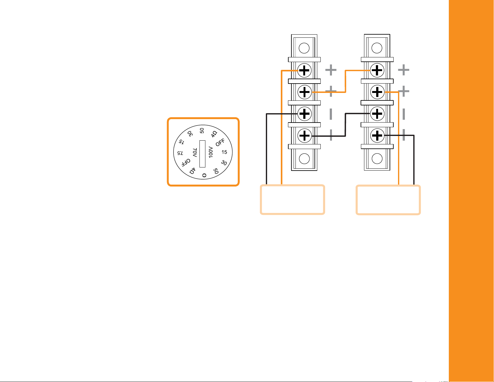
WIR IN G & CO NN ECTIONS
Ensure that all wiring is installed in compliance with local laws,
codes and convention. Obtain all necessary permits and approvals and use only cable that is approved for the application and is
sized to safely accommodate the load.
Models C4 / C4T / C6 / C8 and CSUB
These models include two internal crossover networks allowing
either 4Ω or 16Ω low impedance operation. In addition they
include 70/100V transformers for use in distributed systems.
For 70/100V operation select the
appropriate wattage tap using the
rotary selector switch. Note that one
side of the switch is labeled for 70V
operation and the other side for 100V
systems. Ensure that the power is set
for the correct amplifier connected.
NOTE: DO NOT USE THE “0”
SETTING WHEN CONNECTED TO A 100V SOURCE!
Select the power tap by dividing the amplifier’s available power
by the number of speakers to be connected and then selecting the
next lower wattage tap. For example:
300W amplifier ÷ 20 speakers = 15 Watts; use the
15W terminal
Individual speakers may be tapped higher or lower in order to
better balance the system sound pressure level in different areas.
Ensure that the combined power draw does not exceed the rated
power of the amplifier or else damage to the amplifier and speakers may occur. All 70/100V speakers should be wired in parallel
as shown to the right.
11
Page 12

For low impedance operation first set the rotary switch to indicate the 4Ω setting. Then remove the terminal cover plate and note the
position of the push-button switch. When the switch is in the “UP” position it indicates that the system is in 4Ω mode. When the switch is
in the “DOWN” position it indicates that the system is in 16Ω mode.
CAUTION: Calculate the total load impedance before connecting the power amplifier. Do not exceed the number of speakers that the
amplifier can drive safely:
Amplifier Minimum Impedance 2Ω 4Ω 8Ω
Number of 16Ω Speakers in Parallel
Number of 8Ω Speakers in Parallel
Number of 4Ω Speakers in Parallel
8 4 2
4 2 1
2 1 NO
MOD EL S C4 -8 / C4-16
The C4-8 and C4-16 are fixed-impedance models offering 8Ω and 16Ω impedance respectively. They are designed for direct connection
to low impedance power amplifiers in applications that require relatively few speakers located in close proximity to the amplifier.
Connect multiple speakers in parallel ensuring that the effective speaker load is compatible with the minimum load impedance of the
connected power amplifier.
12
COM PL IA NC E
This product is in compliance with CE directives and bears the CE mark. For detailed information on specific directives please contact
your local QUAD Industrial sales office or distributor.
Page 13

SPE CI FI CATIONS (C4 /C 6/ C8 /C SU B/C4/16)
Power Handling: C4 MODELS C6 C8 CSUB C4-16
Continuous 25W 50W 75W 100W 25W
Program 50W 100W 150W 200W 50W
Peak 100W 200W 300W 400W 100W
Frequency Response: 55Hz−20kHz 50Hz−20kHz 45Hz−20kHz 28Hz−500Hz 55Hz−20kHz
(-10dB)
Frequency Response: 70Hz−20kHz 70Hz−20kHz 55Hz−20kHz 43Hz−120Hz 70Hz−20kHz
(+/-3dB)
Sensitivity (@2.83V): 84dB 86dB 88dB 80dB 84dB
Max SPL: 104dB 109dB 113dB 106dB 104dB
Coverage (H x V): 110˚ x 90˚ 110˚ x 90˚ 110˚ x 90˚ ø 110˚ x 90˚
Directivity (DI) (H x V): 5.34 3.10 5.82 ø 5.34
Impedance: 4 & 16Ω 4 & 16Ω 4 & 16Ω 4 & 16Ω 16Ω
Transducers:
LF Driver Size 4" Cone 6" Cone 8" Cone 10" Long Throw 4" Cone
MID Driver Size ø ø ø ø ø
HF Driver Size 1" Soft Dome 1" Soft Dome Tweeter 1" Soft Dome ø 1" Soft Dome
Tweeter Tweeter Tweeter Tweeter
Crossover Frequency: 2.2kHz 2.5kHz 2.3kHz 150Hx LPF 2.2kHz
Enclosure Material: Plastic (ABS) Plastic (ABS) Plastic (ABS) Plastic (ABS) Plastic (ABS)
metal can metal can metal can metal can metal can
Connector Type: Screw Terminal Screw Terminal Screw Terminal Screw Terminal Screw Terminal
Dimensions: 9.92" x 8.62" 11.61" x 8.62" 13.11" x 9.37" 14.6" x 13.74" 9.92" x 8.62"
(W x D) 252 x 219mm 295 x 219mm 333 x 238mm 371 x 349mm 252 x 219mm
Net Weight: 2.75kg 4.1kg 5.3kg. 9.4kg 2.2kg
6.05lbs. 9.02lbs. 11.66lbs. 20.68lbs. 4.84lbs.
13
Page 14

U S A C O N T A C T :
p h + 8 7 7 . 4 4 0 . 0 8 8 8
p h + 4 2 5 . 8 6 1 . 3 9 0 9
f x + 4 2 5 . 8 6 1 . 3 9 0 6
U K C O N T A C T :
p h + 0 8 4 5 4 5 8 0 0 1 1
p h + 4 4 ( 0 ) 1 4 8 0 4 4 7 7 0 0
f x + 4 4 ( 0 ) 1 4 8 0 4 3 1 7 6 7
O U T S I D E U S A & U K :
p h + 8 6 ( 0 7 5 5 ) 8 2 0 9 6 6 3 9
R E V.1
f x + 8 6 ( 0 7 5 5 ) 8 2 0 9 0 2 0 3
W E B :
w w w . q u a d i n d u s t r i a l . c o m
F O R T H E C L O S E S T A P P R O A C H T O T H E O R I G I N A L S O U N D
© 2006 QUA D In dus tria l. Q UAD In dust rial is a m embe r of th e In tern atio nal Aud io G roup. IAG Amer ica Inc . 84 40 1 54t h Av enue N E · Redm ond , WA 98052
 Loading...