

Qtx LUX-LD01 User Manual

USER MANUAL
LUX-LD01 MINI MOVING HEAD

TABLE OF CONT ENTS
WHAT IS INCLUDED. .. ....... .. ......... ......... ......... ......... ......... ......... ......... ......... ......... .. ....... .. ....... .. ......... ......... ....... 3
UNPACKIN G INSTRUCTI ONS ....... ......... ......... ......... ......... ......... .. ....... .. ......... ......... ......... ......... ......... ......... ...... 3
AC POWER ..... ......... ......... ......... ......... ......... .. ....... .. ......... ......... ......... ......... ......... ......... ......... ......... ......... ........ 3
SAFETY IN STRUCTION S........ ......... ......... ......... ......... ......... .. ....... .. ......... ......... ......... ......... ......... ......... ......... ... 4
1. B EF ORE YOU BEGI N. .. .. ......... .. .. ......... .. .. ......... .. .. .. ......... .. .. ......... .. .. ......... .. .. ........... .. .. ......... . 3
2. I NT RO DU CTION ..... .. .. ......... .. .. ........... .. .. ......... .. .. ......... .. .. ........... .. .. ......... .. .. ......... .. .. ........... 5
FEATUR ES ......... ......... ......... ......... ......... ......... ......... ......... ......... .. ....... .. ......... ......... ......... ......... ......... ......... ..... 5
DMX CHANNEL SUMM ARY 13 CH ANNEL MODE FOR SPO T... ......... ......... ......... ......... ......... ......... ......... ......... ..... 5
DMX CHANNEL SUMM ARY 12 CH ANNEL MODE FOR WASH.... ......... ......... ......... ......... ......... .. ....... .. ....... .. ......... . 5
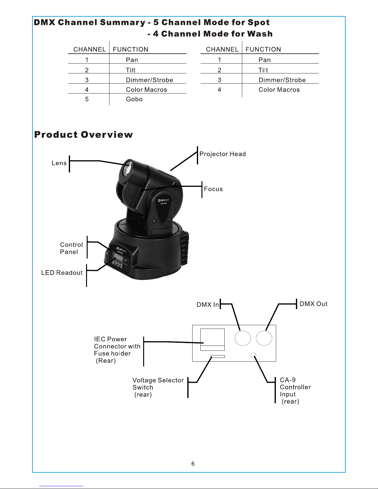
DMX CHANNEL SUMM ARY 5 CHA NNEL MO DE FOR SPOT.. .. ......... ......... ......... ......... ......... ......... ......... ......... ...... 6
DMX CHANNEL SUMM ARY 4 CHA NNEL MO DE FOR WASH..... ......... ......... ......... ......... ......... .. ....... .. ....... .. ......... .. 6
PRODUCT OVERVI EW . ....... .. ......... ......... ......... ......... ......... ......... ......... ......... ......... .. ....... .. ....... .. ......... ......... .... 6
3. S ET UP ........ .. .. ......... .. .. ........... .. .. ......... .. .. ......... .. .. ........... .. .. ......... .. .. ......... .. .. ........... .. .. ....... 7
FUSE REPLAC EMENT......... ......... ......... ......... ......... ......... .. ....... .. ......... ......... ......... ......... ......... ......... ......... ....... 7
FIXTURE LIN KING ...... ......... ......... ......... .. ....... .. ....... .. ......... ......... ......... ......... ......... ......... ......... ......... ......... .. .... 7
Data Cablin g ......... ......... ......... ......... .. ....... .. ......... ......... ......... ......... ......... ......... ......... ......... ......... ......... .. ....... 7
DMX Data Cabl e........ ......... ......... ......... .. ....... .. ....... .. ......... ......... ......... ......... ......... ......... ......... ......... ......... .. . 7
Cable Conne ctors ..... ......... ......... .. ....... .. ....... .. ......... ......... ......... ......... ......... ......... ......... ......... ......... .. ....... .. . 8
3-Pin to 5-Pi n Conversio n Chart ..... .. ....... .. ......... ......... ......... ......... ......... ......... ......... ......... ......... ......... .. ....... . 8
SETTING UP A D MX SERIAL DATA LINK ..... ......... ......... ......... ......... .. ....... .. ....... .. ......... ......... ......... ......... ......... ... 8
MASTER/SL AVE FIXTUR E LINKING.. ......... ......... ......... ......... ......... .. ....... .. ......... ......... ......... ......... ......... ......... ... 9
MOUNTING .. ......... ......... ......... ......... ......... .. ....... .. ......... ......... ......... ......... ......... ......... ......... ......... ......... ......... .. 9
Orientati on ........ ......... ......... ......... .. ....... .. ....... .. ......... ......... ......... ......... ......... ......... ......... ......... ......... .. ....... . 9
Rigging ... ......... ......... ......... ......... ......... .. ....... .. ......... ......... ......... ......... ......... ......... ......... ......... ......... .. ....... .. 9
4. O PE RATING INSTRUCTI ON S. ......... .. .. .. ......... .. .. ......... .. .. ......... .. .. .. ......... .. .. ......... .. .. ......... .. .. .10
NAVIGATING THE C ONTROL PANEL ..... .. ......... ......... ......... ......... ......... ......... ......... ......... ......... ......... .. ....... .. ....10
MENU MAP... ......... ......... ......... ......... ......... ......... ......... ......... .. ....... .. ....... .. ......... ......... ......... ......... ......... ......... .11
USER CONFIG URATIONS . ......... ......... ......... ......... ......... ......... ......... .. ....... .. ......... ......... ......... ......... ......... .......11
USER CONFIG URATIONS . ......... ......... ......... ......... ......... ......... ......... .. ....... .. ......... ......... ......... ......... ......... .......12
To set the pa n to i nverting or n on-invert ing: ...... ......... ......... .. ....... .. ......... ......... ......... ......... ......... ......... ......... .12
To set the ti lt t o inverting o r non-inver ting:.... ......... ......... .. ....... .. ......... ......... ......... ......... ......... ......... ......... ......12
To set the LE D Re adout to Inve rting or Non- Inverting : ......... .. ....... .. ....... .. ......... ......... ......... ......... ......... ......... .12
To set the DM X ch annel confi guration: ......... ......... ......... .. ....... .. ....... .. ......... ......... ......... ......... ......... ......... .....12
To set the ma xi mum pan angle : ......... ......... ......... ......... ......... ......... .. ....... .. ......... ......... ......... ......... ......... ......12
To set the ma xi mum tilt angl e: ........ ......... ......... ......... ......... ......... .. ....... .. ....... .. ......... ......... ......... ......... ......... 12
Service Fun ctions .... ......... ......... .. ....... .. ....... .. ......... ......... ......... ......... ......... ......... ......... ......... ......... .. ....... .. ....12
To reset th e fi xture:... ......... ......... ......... ......... ......... ......... ......... .. ....... .. ....... .. ......... ......... ......... ......... ......... ...12
To restor e al l settings to t heir factor y defaults: . ......... ......... .. ....... .. ......... ......... ......... ......... ......... ......... ......... ..12
OPERATIO N........ ......... ......... ......... ......... ......... ......... ......... ......... .. ....... .. ......... ......... ......... ......... ......... ......... ..13
Stand-Alo ne Mode (Soun d- Active, Au to M ode): ..... ......... ......... ......... ......... ......... ......... ......... .. ....... .. ....... .. ........1 3
Master/Sl ave Mode (Mas ter Sound, Ma st er Auto): .... ......... ......... ......... ......... ......... ......... ......... ......... .. ....... .. ......1 3
DMX Mode .... ......... ......... ......... ......... ......... .. ....... .. ......... ......... ......... ......... ......... ......... ......... ......... ......... .......13
DMX CHANNEL VAL UES (13 CHANN EL FOR SP OT) ....... ......... ......... ......... ......... ......... ......... ......... .. ....... .. ......... 14
DMX CHANNEL VAL UES (12 CHANN EL FOR WASH) . ......... ......... ......... ......... .. ....... .. ......... ......... ......... ......... .....15
DMX CHANNEL VAL UES (5 CHANNE L FOR SPO T) ........ ......... ......... ......... ......... ......... ......... ......... .. ....... .. ......... .16
DMX CHANNEL VAL UES (4 CHANNE L FOR WASH) .. ......... ......... ......... ......... .. ....... .. ......... ......... ......... ......... ......16
5. A PP ENDIX.... .. .. ......... .. .. ........... .. .. ......... .. .. ......... .. .. ........... .. .. ......... .. .. ......... .. .. ........... .. .. .....17
TECHNICAL SPEC IF ICATIO NS ........ ......... .. ....... .. ......... ......... ......... ......... ......... ......... ......... ......... ......... ......... .. 17
2

1 x Macro Spot/wash
User Manual
What is included
1. BEFORE YOU BEGIN
Unpacking Instructions
Immediately upon receiving a fixture, carefully unpack the carton, check the contents to ensure that
all parts are present, and have been received in good condition. Notify the shipper immediately and
retain packing material for inspection if any parts appear damaged from shipping or the carton itself
shows signs of mishandling. Save the carton and all packing materials. In the event that a fixture
must be returned to the factory, it is important that the fixture be returned in the origi na l fa ct or y bo x
and packing.
AC Power
Fi gure 1 - AC Vo lt ag e Swi tch
To determine the power requirements for a particular fixture, see the label affixed to t he b ac k pl at e of
the fixture or refer to the fixture’s specifications chart. A fixture’s listed current rating is its average
current draw under normal conditions. All fixtures must be powered directly off a switched circu it a nd
cannot be run off a rheostat (variable resistor) or dimmer circuit, even if the rheostat or d im me r
channel is used solely for a 0% to 100% switch. Before applying power to a fixture, check that the
source voltage matches the fixture’s requirement. Check the fixture or
device carefully to make sure that if a voltage selection switch exists that it
is set to the correct line voltage you will use.
War ning! Ve rify th at t he voltage select sw itch on your unit matche s the
li ne voltag e app lied. D amage t o yo ur fixt ure m ay result if th e
li ne voltag e app lied do es not match th e vo ltage i ndicate d on
th e vo ltage s elect or switch. Al l fixtu res m ust be conn ected t o
ci rcu its with a su ita ble Ear t h Ground.
Not all fixtures have a voltage
select switch. Please be sure to
connect to the proper voltage.
3

Safety Instr uctions
Please read these ins tructions carefully, it includes important
information about t he installation, usage and maintenance of this
product.
Please keep this User Guide for future consultation. If you sell the unit to another user, be sure that
they also receive this instruction booklet.
Always make sure that you are connecting to the proper voltage, and that the line voltage you are
connecting to is not higher than that stated on the decal or rear panel of the fixture.
This product is intended for indoor use only!
To prevent risk of fire or shock, do not expose fixture to rain or moisture. Make sure there are no
flammable materials close to the unit while operating.
The unit must be installed in a location with adequate ventilation, at least 20in (50cm) from adjac en t
surfaces. Be sure that no ventilation slots are blocked.
Always disconnect from power source before servicing or replacing fuse and be sure to replace with
same fuse size and type.
Secure fixture to fastening device using a safety chain. Never carry the fixture solely by its head. Use
its carrying handles.
Maximum ambient temperature (Ta) is 104°F (40°C). Do not operate fixture at temperatures higher
than this.
In the event of a serious operating problem, stop using the unit immediately. Never try to rep ai r th e
unit by yourself. Repairs carried out by unskilled people can lead to damage or malfunction. Please
contact the nearest authorized technical assistance center. Always use the same type spare parts.
Don’t connect the device to a dimmer pack.
Make sure the power cord is never crimped or damaged.
Never disconnect the power cord by pulling or tugging on the cord.
Avoid direct eye exposure to the light source while it is on.
4

2. INTRODUCTION
Features
5 or 13-channel DMX-512 LED moving yoke
Pan: 540o / tilt: 270o
RGB color mixing
Gobo wheel
9 gobos + open
Gobo wheel spin effect
Variable electronic strobe
Variable electronic dimmer (0 – 100%)
Vector speed channel for pan/tilt, RGB color mixing and color macros
Built-in movement macros via master/slave or DMX
User-selectable basic or advanced operating modes
User-selectable pan/tilt ranges
Pan: 540°, 360°, 180°
Tilt: 270°, 180°, 90°
Compact and lightweight
LED display menu with invert
Reset to factory settings option
Display auto on/off
Pan/tilt invert option
Fan cooled
DMX Channel Summar y - 13 Channel Mode for Spot
- 12 Channel Mode for Wash
OPTIONAL CONTROLLERS
Easy Controller (CA-9)
ADDITIONAL FEATURES
CONTROL FEATURES
CHANNEL FUNCTION
1 Pan
2 Pan Fine
3 Tilt
4 Tilt Fine
5 Vecto r Speed (Pan/Tilt)
6 Dimm er/Strobe
7 Red
8 Gree n
9 Blue
10 Col or Macros
11 Vector Spee d (Color)
12 Mov ement Macros
13 Gob o
CHANNEL FUNCTION
1 Pan
2 Pan Fine
3 Tilt
4 Tilt Fine
5 Vecto r Speed (Pan/Tilt)
6 Dimm er/Strobe
7 Red
8 Gree n
9 Blue
10 Col or Macros
11 Vector Spee d (Color)
12 Mov ement Macros
5
 Loading...