

Page 1
Q-TECH
COR PORATI ON
Description
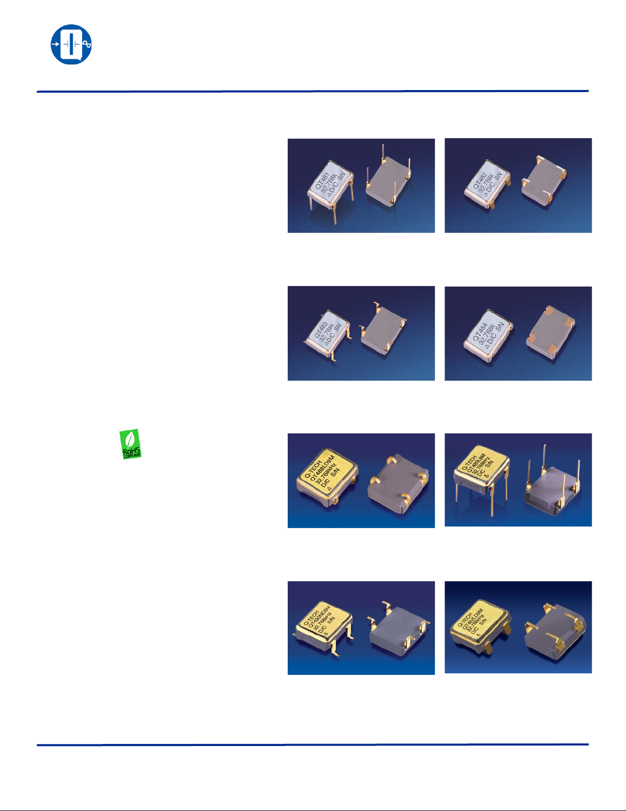
Q-Tech’s leaded or surface-mount miniature QT481 and
QT488 oscillators consist of an IC 2.5Vdc and 3.3Vdc,
clock square wave generator and a miniature round or
strip AT quartz crystal built in a low profile ceramic
package with gold plated contact terminals.
Features
• Made in the USA
• ECCN: EAR99
• +3.3Vdc or +2.5Vdc operation
• 32.768kHz square wave CMOS output
• Wide operating temperature (*)
• Stand-by function:
High Impedance in stand-by mode oscillator stops
• Excellent AT cut crystal temperature characteristics
• Tristate output option (D)
• Fundamental design
• Able to meet 36,000g shock half-sine
• Fast Start-up time
• RoHS compliant
QT481 AND QT488 SERIES
ULTRA-LOW CURRENT REAL TIME CLOCK OSCILLATORS
2.5Vdc and 3.3Vdc - 32.768kHz
(*) Available in high temperature for down-hole
application. Call Q-Tech for details
Applications
• Real-time clock driver
• 32.768kHz output crystal modules
Package Information
• Package material: 91% AL2O
• Lead material: Kovar
• Lead finish:
Gold Plated: 50μ ~ 80μ inches
Nickel Underplate: 100μ ~ 250μ inches
• Weight: 0.6g typ., 3.0g max.
Q-T ECH Co rpo rat ion - 1 015 0 W. J efferson Boulevard, Culver City 90232 - Tel: 310-836-7900 - Fax: 310-836-2157 - www.q-t e c h.c om
3
QPDS-0008 (Revision A, June 2013) (ECO # 10907)
1 of 7
Page 2

Q-TECH
COR PORATI ON
Electrical Characteristics
Parameters +3.3Vdc +2.5Vdc
QT481 AND QT488 SERIES
ULTRA-LOW CURRENT REAL TIME CLOCK OSCILLATORS
2.5Vdc and 3.3Vdc - 32.768kHz
Output frequency range (Fo)
Supply voltage (Vdd)
Maximum Applied Voltage
(Vdd max.)
Frequency stability (∆F/∆T) See Ordering Information
Operating temperature (Topr) See Ordering Information
Storage temperature (Tsto) -55ºC to + 125ºC
Operating supply current
(Idd) (No Load)
Symmetry
(50% of ouput waveform)
Rise and Fall times
(Tr, Tf betweeen 10% and 90% of output waveform)
Output Load
Start-up time (Tstup) 10ms max.
Output voltage (Voh/Vol)
Output Current (Ioh/Iol)
Enable/Disable function Pin 1
+3.3Vdc ± 10%
0.42 mA typ., 0.7mA max.
50/50% typ., 45/55% max.
0.9 x Vdd min.; 0.1 x Vdd max.
VIL ≤ 0.3Vdd: High Impedance
Stand-by current: 10µA max.
32.768kHz
+5Vdc
0.2µs typ., 1µs max.
15pF
± 2mA min.
VIH ≥ 0.7Vdd: Active
+2.5Vdc ± 10%
0.24 mA typ., 0.5mA max.
Aging ± 5ppm max. first year / ± 2ppm max. per year thereafter
Q-T ECH Co rpo rat ion - 1 015 0 W. J efferson Boulevard, Culver City 90232 - Tel: 310-836-7900 - Fax: 310-836-2157 - www.q-te ch .com
QPDS-0008 (Revision A, June 2013) (ECO # 10907)
2 of 7
Page 3
Q-TECH
(5.080 ± 0.13)
0.200 ± .005
0.040
(1.02)
0.197 ± .006
(5.00 ± 0.15)
0.276 ± .006
(7.0 ± 0.2)
(2.54)
0.100
12
43
0.018±.003
(.46±0.08)
(.20 ± 0.03)
0.008 ± .001
(5.08 ± 0.2)
0.200 ± .008
max.
0.205 ± .010
(5.20 ± 0.25)
R 0.20
(R .008)
(4X)
(0.20)
0.008
0.200±.005
(5.80±0.13)
0.028
(0.72)
P/N
FREQ.
D/C S/N
0.197 ± .006
(5.00 ± 0.15)
0.276 ± .006
(7.0 ± 0.2)
12
43
(5.08 ± 0.2)
0.200 ± .008
R 0.20
(R .008)
(4X)
0.060 ± .003
(1.52 ± 0.08)
(.203)
0.008
(1.40 ± 0.08)
0.055 ± .003
0.216
(5.49)
(2.54)
0.100
max.
0.018±.003
(.46±0.08)
(0.20)
0.008
0.028
(0.72)
P/N
FREQ.
D/C S/N
3º to 5º typ.
detail A’
A’
(1.40 ± 0.08)
0.055± .003
0.216
(5.49)
(.203)
0.008
0.197 ± .006
(5.00 ± 0.15)
0.276 ± .006
(7.0 ± 0.2)
(5.08 ± 0.2)
0.200 ± .008
R 0.200
(R .008)
(4X)
0.060 ± .003
(1.52 ± 0.08)
(2.54)
0.100
max.
0.018±.003
(.46±0.08)
(0.20)
0.008
0.028
(0.72)
2
43
1
P/N
FREQ.
D/C S/N
A’
3º to 5º typ.
detail A’
.102
(2.6)
0.055
(1.4)
0.040
(1.0)
(2.0)
0.079
12
34
max.
0.197±.006
(5.00±0.15)
0.276±.006
(7.0±0.2)
12
43
(5.08±0.2)
0.2±.008
R 0.200
(R .008)
(4X)
P/N
FREQ.
D/C S/N
0.290±0.005
(7.37±0.13)
0.350±0.005
(8.89±0.13)
0.100±0.005
(2.54±0.13)
0.200±0.005
(5.08±0.13)
0.170 Max.
(4.32)
0.018±0.003
(0.457±0.076)
0.315 max.
(8.00 max.)
0.240±0.005
(6.10±0.13)
0.040 Max.
(1.02)
12
43
Q-TECH
P/N
FREQUENCY
D/C S/N
1
2
4
3
0.350±0.005
0.290±0.005
0.130
0.018±.003
(8.00 max.)
(5.080±0.13)
0.100±.005
0.200±.005
(.457±0.076)
(8.89±0.13)
(7.37±0.13)
(2.54±0.13)
(5.080±0.13)
(3.30)
0.050
(1.27)
(.203)
FREQ.
Q-TECH
D/C S/N
0.315 max.
0.200±.005
0.008
MAX.
P/N
.190 MAX.
(4.826 MAX.)
(.203)
(8.00 max.)
(10.16 ± .13)
.008
.315 max.
.400 TYP.
1
2
4
3
.350 ± .005
.290 ± .005
.100 ± .005
.200 ± .005
(8.89 ± .13)
(7.37 ± .13)
(2.54 ± .13)
(5.08 ± .13)
FREQ.
Q-TECH
D/C S/N
4 X
.048 ± .002
(1.22 ± .051)
4 X
.018 ± .003
(.457 ± .076)
P/N
4 X
.290 ± .005
.190 MAX.
(1.396 ± .13)
.200 ± .005
.048 ± .002
(1.22 ± .051)
(7.37 ± .13)
(5.08 ± .13)
.100 ± .005
(2.54 ± .13)
(4.826 MAX.)
(.203) (2.794 ± .13)
(8.00 max.)
.315 max.
.055 ± .005
.008
.110 ± .005
1 2
43
.350 ± .005
(8.89 ± .13)
4 X
.018 ± .003
(.457 ± .076)
Q-TECH
P/N
FREQ.
D/C S/N
ULTRA-LOW CURRENT REAL TIME CLOCK OSCILLATORS
COR PORATI ON
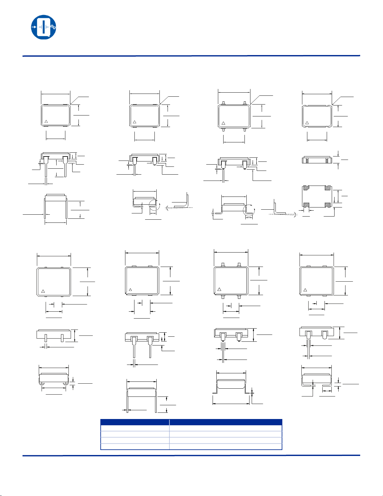
Package Outline and Pin Connections - Dimensions are in inches (mm)
QT481 AND QT488 SERIES
2.5Vdc and 3.3Vdc - 32.768kHz
QT481
QT488
QT482
QT489
QT483
QT490
QT484
QT492
QPDS-0008 (Revision A, June 2013) (ECO # 10907)
Pin No.
1
2
3
4
Function
TRISTATE or NC
GND/CASE
OUTPUT
VDD
Q-T ECH Co rpo rat ion - 1 015 0 W. J efferson Boulevard, Culver City 90232 - Tel: 310-836-7900 - Fax: 310-836-2157 - www.q-t e c h.c om
3 of 7
Page 4

Q-TECH
COR PORATI ON
Ordering Information
Solder Dip Option:
T = Standard
S = Solder Dip (*)
G = Solder Dip (*)
QT481 AND QT488 SERIES
ULTRA-LOW CURRENT REAL TIME CLOCK OSCILLATORS
2.5Vdc and 3.3Vdc - 32.768kHz
(Sample part number)
QT488 L D 1 0 M - 32.768kHz
Q T 4 88 L D 10 M - 32.768kHz
Output Frequency
Ultra-Low Current
Real Time Clock Oscillator
Package:
(See page 3)
Logic & Supply Voltage:
L = LVHCMOS +3.3V
N = LVHCMOS +2.5V
Tristate Option:
Blank = No Tristate
D = Tristate
Blank=No Screening
1 = ± 100ppm at 0ºC to +70ºC
4 = ± 50ppm at 0ºC to +70ºC
5 = ± 25ppm at -20ºC to +70ºC
6 = ± 50ppm at -55ºC to +105ºC
7 = ± 75ppm at -55ºC to +125ºC
9 = ± 50ppm at -55ºC to +125ºC
10 = ± 100ppm at -55ºC to +125ºC
11 = ± 50ppm at -40ºC to +85ºC
12 = ± 100ppm at -40ºC to +85ºC
Screening Option:
M=Per MIL-PRF-55310, Level B
Frequency vs. Temperature Code (**) :
(*) Hot Solder Dip options for an additional cost:
S = Sn60/Pb40 per MIL-PRF 55310
G = Lead free Alloy SAC305 (96.5% Sn, 3% Ag, 0.5% Cu)
(**) Frequency stability vs. temperature codes may not be available in all frequencies.
For Non-Standard requirements, contact Q-Tech Corporation at Sales@Q-Tech.com
Packaging Options
• Standard packaging in anti-static plastic tube (60 pcs/tube)
• Tape and Reel (800 pcs/reel) is available for an additional charge.
Other Options Available For An Additional Charge
• P. I. N. D. test
Specifications subject to change without prior notice.
Q-T ECH Co rpo rat ion - 1 015 0 W. J efferson Boulevard, Culver City 90232 - Tel: 310-836-7900 - Fax: 310-836-2157 - www.q-t e c h.c om
QPDS-0008 (Revision A, June 2013) (ECO # 10907)
(MIL-STD 883, Method 2020)
4 of 7
Page 5

Q-TECH
-
-
Output
Ground
4
3
2
0.1µF
15pF
1
Tristate Function
Power
supply
10k
mA
Vdc
+
+
+
(*)
or
0.01µF
QT88
(*) CL includes probe and jig capacitance
Typical test circuit for CMOS logic
-250
-200
-150
-100
-50
0
50
100
150
200
250
0 10 20 30 40 50 60 70 80 90 100 110 120 130 140 150 160 170 180 190 200
Frequency Stability (PPM)
Temperature (°C)
Typ e: QT88LD8M Vcc Input:3.3 Out Freq:32.768Khz +/-250ppm@ 0 to 200 deg.C
45º 45º
Hybrid Case
Substrate
Die
D/A epoxy
D/A epoxy
Heat
Die
R1
D/A epoxy
Substrate
D/A epoxy
Hybrid Case
R2 R3 R4 R5
JA JC CA
Die
T
T
T
C
A
J
CA
JC
COR PORATI ON
QT481 AND QT488 SERIES
ULTRA-LOW CURRENT REAL TIME CLOCK OSCILLATORS
2.5Vdc and 3.3Vdc - 32.768kHz
Output Waveform (Typical)
Frequency vs. Temperature Curve
Test Circuit
The Tristate function on pin 1 has a built-in pull-up resistor typical 50kΩ, so it can
be left floating or tied to Vdd without deteriorating the electrical performance.
Start up Time
Thermal Characteristics
The heat transfer model in a hybrid package is described in figure 1.
Heat spreading occurs when heat flows into a material layer of increased
cross-sectional area. It is adequate to assume that spreading occurs at a
45° angle.
The total thermal resistance is calculated by summing the thermal
resistances of each material in the thermal path between the device and
hybrid case.
RT = R1 + R2 + R3 + R4 + R5
The total thermal resistance RT (see figure 2) between the heat source
(die) to the hybrid case is the Theta Junction to Case (Theta JC) in°C/W.
• Theta junction to case (Theta JC) for this product is 30°C/W.
• Theta case to ambient (Theta CA) for this part is 100°C/W.
• Theta Junction to ambient (Theta JA) is 130°C/W.
Maximum power dissipation PD for this package at 25°C is:
• PD(max) = (TJ (max) – TA)/Theta JA
• With TJ = 175°C(Maximum junction temperature of die)
• PD(max) = (175 – 25)/130 = 1.15W
Q-T ECH Co rpo rat ion - 1 015 0 W. J efferson Boulevard, Culver City 90232 - Tel: 310-836-7900 - Fax: 310-836-2157 - www.q-t e c h.c om
QPDS-0008 (Revision A, June 2013) (ECO # 10907)
(Figure 1)
(Figure 2)
5 of 7
Page 6

Q-TECH
Ø178±1
26
FEEDING (PULL) DIRECTION
Ø13.0±0.5
120°
2.5
4.699±0.1
Ø1.5
16±0.1
2.0
1.75±0.1
0.3±.005
2.0±0.1
7.747±0.1
4.0±0.1
or
Ø330±1
Ø1.5
9.271
5°Max
24.0±0.3
11.5
P/N
FREQUENCY
D/C S/N
0 20 40 60 80 100 120 140 160
180
200 220 240 260
280
300 320 340 360 380 400 420 Time (s)
25
50
75
100
125
150
175
200
225
250
TEMP(*C)
0
60s min.
120s max.
60s min.
120s max.
225º min.
240º max.
60s min.
150s max.
240º
Ramp down (6ºC/s Max)
Ramp up (3ºC/s Max)
TYPICAL REFLOW PROFILE FOR Sn-Pb ASSEMBLY
COR PORATI ON
QT481 AND QT488 SERIES
ULTRA-LOW CURRENT REAL TIME CLOCK OSCILLATORS
2.5Vdc and 3.3Vdc - 32.768kHz
Reflow Profile
The five transition periods for the typical reflow process are:
• Preheat
• Flux activation
• Thermal equalization
• Reflow
• Cool down
Environmental Specifications
Q-Tech Standard Screening/QCI (MIL-PRF55310) is available for all of our QT481 and QT488 series. Q-Tech can also customize
screening and test procedures to meet your specific requirements. The QT481 and QT488 series are designed and processed to exceed
the following test conditions:
Temperature cycling MIL-STD-883, Method 1010, Cond. B
Constant acceleration MIL-STD-883, Method 2001, Cond. A, Y1
Seal: Fine and Gross Leak MIL-STD-883, Method 1014, Cond. A and C
Burn-in 160 hours, 125°C with load
Aging 30 days, 70°C, ±1.5ppm max
Vibration sinusoidal MIL-STD-202, Method 204, Cond. D
Shock, non operating MIL-STD-202, Method 213, Cond. I (See Note 1)
Thermal shock, non operating MIL-STD-202, Method 107, Cond. B
Ambient pressure, non operating MIL-STD-202, 105, Cond. C, 5 minutes dwell time minimum
Resistance to solder heat MIL-STD-202, Method 210, Cond. B
Moisture resistance MIL-STD-202, Method 106
Terminal strength MIL-STD-202, Method 211, Cond. C
Resistance to solvents MIL-STD-202, Method 215
Solderability MIL-STD-202, Method 208
ESD Classification MIL-STD-883, Method 3015, Class 1 HBM 0 to 1,999V
Moisture Sensitivity Level J-STD-020, MSL=1
Note 1: Additional shock results successfully passed on 16MHz, 20MHz, 24MHz, 40MHz, and 80MHz
QPDS-0008 (Revision A, June 2013) (ECO # 10907)
Embossed Tape and Reel Information For QT488
Dimensions are in mm. Tape is compliant to EIA-481-A.
Reel size vs. quantity:
Reel size (Diameter in mm)
178
330
Environmental Test Test Conditions
• Shock 850g peak, half-sine, 1 ms duration (MIL-STD-202, Method 213, Cond. D modified)
• Shock 1,500g peak, half-sine, 0.5ms duration (MIL-STD-883, Method 2002, Cond. B)
• Shock 36,000g peak, half-sine, 0.12 ms duration
Q-T ECH Co rpo rat ion - 1 015 0 W. J efferson Boulevard, Culver City 90232 - Tel: 310-836-7900 - Fax: 310-836-2157 - www.q-t e c h.c om
Please contact Q-Tech for higher shock requirements
Qty per reel (pcs)
150
800
6 of 7
Page 7

QT481 AND QT488 SERIES
Q-TECH
COR PORATI ON
ULTRA-LOW CURRENT REAL TIME CLOCK OSCILLATORS
2.5Vdc and 3.3Vdc - 32.768kHz
Revision History
ECO REV REVISION SUMMARY PAGE DATE
- Initial Release 10/26/2010
Change Package Material from 90% to 91% 1
10907 A
Add Lead Free Tinning to Solder Dip Option
Add Code 7 to Frquency vs. Temperature Code table
Add document number to footer All
4
6/13/2013
Q-T ECH Co rpo rat ion - 1 015 0 W. J efferson Boulevard, Culver City 90232 - Tel: 310-836-7900 - Fax: 310-836-2157 - www.q-t e c h.c om
QPDS-0008 (Revision A, June 2013) (ECO # 10907)
7 of 7
 Loading...