


HARDWARE INSTALLATION AND REFERENCE GUIDE
www.qtech.ru
QSW-6200 Series Switch
Hardware Installation and Reference V1.0

QSW-6200 Series Switch Hardware Installation and Reference Guide 2
www.qtech.ru
Copyright Statement
QTECH©2017
QTECH reserves all copyrights of this document. Any reproduction, excerption, backup, modification, transmission,
translation or commercial use of this document or any portion of this document, in any form or by any means, without the
prior written consent of QTECH is prohibited.
Exemption Statement
This document is provided “as is”. The contents of this document are subject to change without any notice. Please obtain
the latest information through the QTECH website. QTECH endeavors to ensure content accuracy and will not shoulder
any responsibility for losses and damages caused due to content omissions, inaccuracies or errors.
QSW-6200 Series Switch Hardware Installation and Reference Guide 3
www.qtech.ru
Preface
Thank you for using our products. This manual will guide you through the installation of the device.
This manual describes the functional and physical features and provides the device installation steps, hardware
troubleshooting, module technical specifications, and specifications and usage guidelines for cables and connectors.
Audience
It is intended for the users who have some experience in installing and maintaining network hardware. At the same time, it
is assumed that the users are already familiar with the related terms and concepts.
Obtaining Technical Assistance
QTECH Website: http://www.qtech.ru
Technical Support: https://helpdesk.qtech.ru/
Related Documents
Documents
Description
Configuration Guide
Describes network protocols and related mechanisms that supported by the
product, with configuration examples.
Command Reference
Describes the related configuration commands, including command modes,
parameter descriptions, usage guides, and related examples.
Symbol Conventions
Means reader take note. Notes contain helpful suggestions or references.
Means reader be careful. In this situation, you might do something that could result in equipment damage or loss of
data.

QSW-6200 Series Switch Hardware Installation and Reference Guide 4
www.qtech.ru
1 Product Overview
QTECH QSW-6200 series switches are the next-generation Layer 3 switches. Featuring high performance, reliable
security, and multiple services, QSW-6200 series switches are mainly applicable to the convergence layer of large-scale
networks to provide full line-rate exchanging. Complete QoS features differentiate services according to business needs
to ensure the prompt transmission of key data. The QSW-6200 series switches provide various interfaces to meet the
requirement for interfaces in network constructions.
QSW-6200 Series Switches
Model
10/100/1000
Base-T
Auto-sensin
g Ethernet
Port
1000M SFP
Port
10G SFP+
Port
MGMT
Port
USB
Port
Mini
USB
Port
Console
Port
Expansion
Module
Slot
RPS
QSW-620
0-32T
28
4
(4 Combo)
4 1 1 1 1 2 Dual
QSW-620
0-52T
48
N/A 4 1 1 1 1 2
Dual
QSW-620
0-32F
8
28
(8 combo)
4 1 1 1 1 2 Dual
Combo port consists of one 1000Base-X SFP port and one10/100/1000Base-T auto-sensing Ethernet port. That is,
only one port of them is available at a particular time.
SFP+ port supports both 10Gbase-R and 1000base-X.
QSW-6200 series switches have the following external ports:
MGMT port: This port is a 10/100/1000M management port. It is used to connect with an Ethernet port of a PC to
perform program. It also supports Data Center Manageability Interface (DCMI) protocol, and users can do remote
management and maintenance for the switch through the port. Use standard network cables when the port is
connected with an Ethernet port.
USB port: The Universal Serial Bus (USB) port is used to connect with USB memory to save logs, host versions,
warnings and other diagnostic messages.
Console port: This port applies RS-232 interface electrical level and standard RJ45 connectors. It is used to
connect the serial ports of the terminal PC to perform tasks including system commissioning, configuration,
maintenance, management, and software loading.
Mini USB port: This port can be used as a serial port for installing the software driver.
The QSW-6200 series supports both Console and Mini USB ports to conduct commissioning, configuration,
maintenance, management, and software loading. However, these functions are activated on only one of them at a

QSW-6200 Series Switch Hardware Installation and Reference Guide 5
www.qtech.ru
particular time.
QSW-6200 series switch is a class A product. In a domestic environment, this product may cause radio
interference in which case the user may be required to take adequate measures.
Warning: Disconnect the power source prior to open case, and close case before restoring power.
Warning: Hazardous moving parts. Keep away from moving fan blades.
For DC input: Reinforce insulation or double insulation must be provided to isolate DC source from the AC mains
supply.
For DC input: A readily accessible disconnect device shall be incorporated in the building installation wiring.
For AC input: the socket-outlet shall be installed near the equipment and shall be easily accessible.
Because the device has several power supplies, disconnect all of them to switch off the device.
When installing the unit, always make the ground connection first and disconnect it last.
The device must be connected permanently to the protection ground before an operation. The cross sectional
area of protective ground conductor shall be at least 0.75 mm².
1.1 QSW-6200-32T
Technical Specifications
Model
QSW-6200-32T
Expansion Module
Slot
2 slots
Power Module
Slot
2 slots
AC input:
Rated voltage: 100V to 240V
Maximum voltage: 90V to 264V
Frequency: 50/60 Hz
Rated current per input: 2A
HVDC input:
Rated voltage: 120V to 340V
Maximum voltage: 110V to 380V
Rated current per input: 2A
DC input:
Rated voltage: -36V to -72V
Rated current per input: 3.15A
QSW-6200 Series Switch Hardware Installation and Reference Guide 6
www.qtech.ru
SFP Port
1000Base-X
100Base-X
SFP+ Port
10GBase-R
1000Base-X
Power
Consumption
≤45W (without expansion modules)
Temperature
Operating temperature: 0 ºC to 50ºC
Storage temperature: -40 ºC to 70ºC
Humidity
Operating humidity: 10% to 90% RH
Storage humidity: 5% to 95% RH
Fan
Speed adjustment and fault alarm
Temperature
Alarm
Supported
Dimensions
(W x D x H)
440 mm x 280 mm x 44 mm
Weight
3.9 kg
Product Appearance
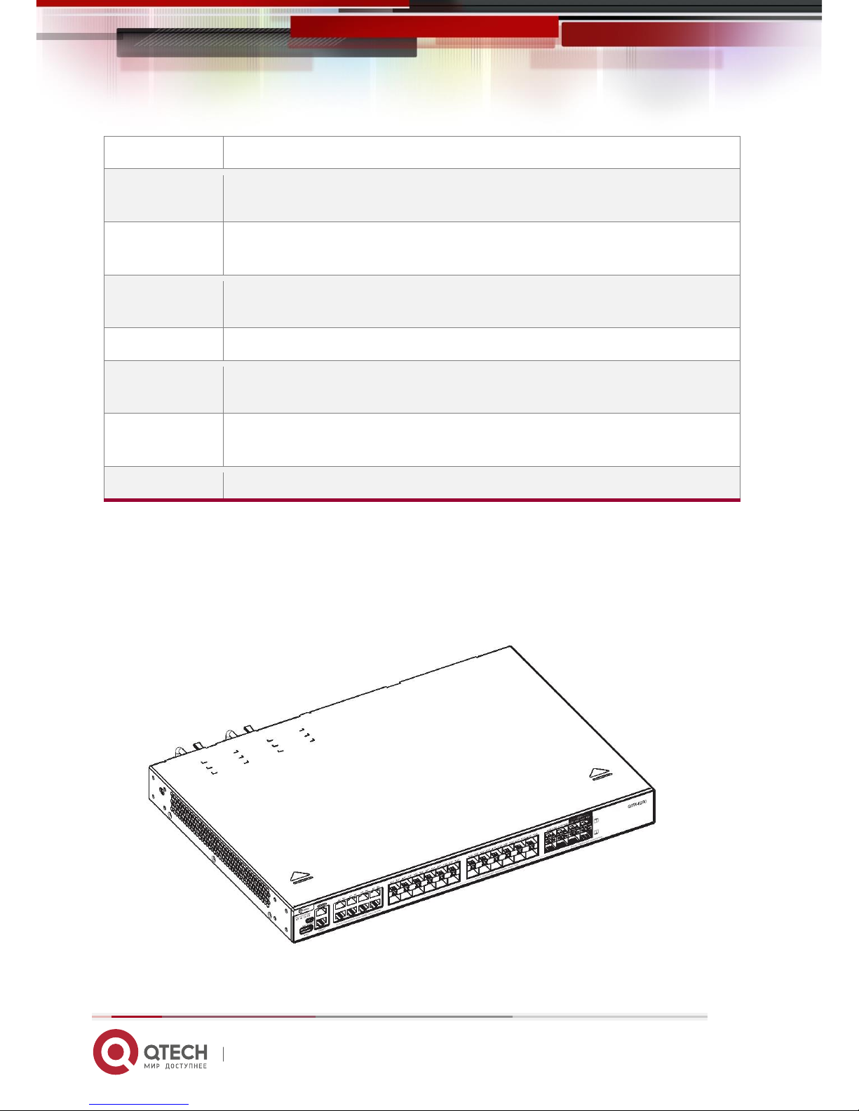
The QSW-6200-32T Ethernet switch provides 28 10/100/1000Base-T Ethernet ports, 4 GE SFP combo ports, 4 10GE
SFP+ ports, 1 MGMT port, 1 USB port, 1 Mini USB port, and 1 Console port on the front panel, as well as 2 power module
slots and 2 expansion module slots on the back panel (The Console and Mini USB ports are a combo Console port. When
they are connected meanwhile, the Mini USB port takes the precedence).
QSW-6200 Series Switch Hardware Installation and Reference Guide 7
www.qtech.ru
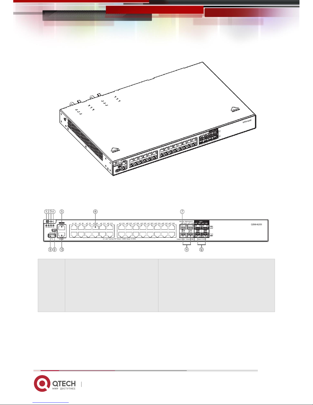
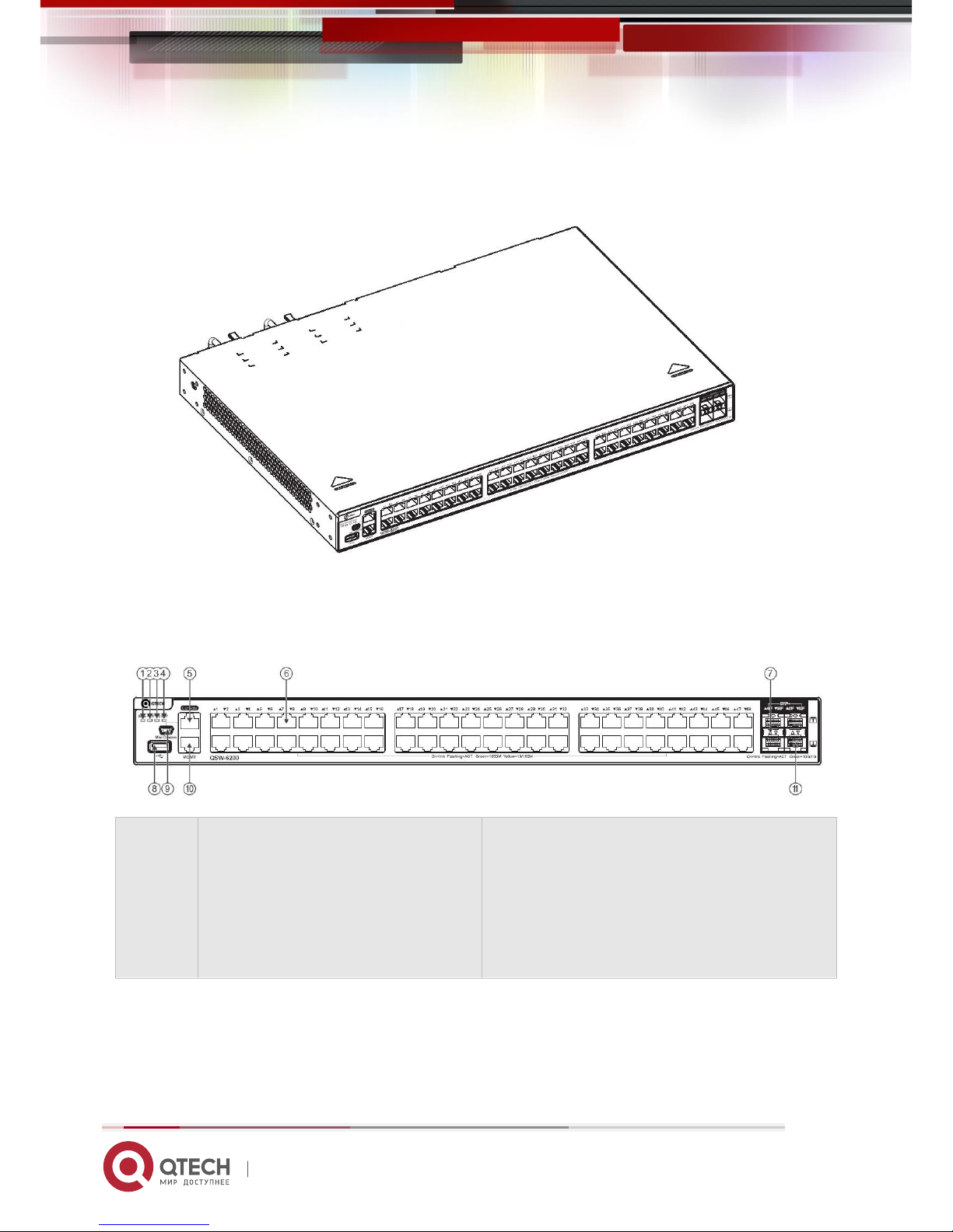
Figure 1-1 Appearance of QSW-6200-32T
Front Panel
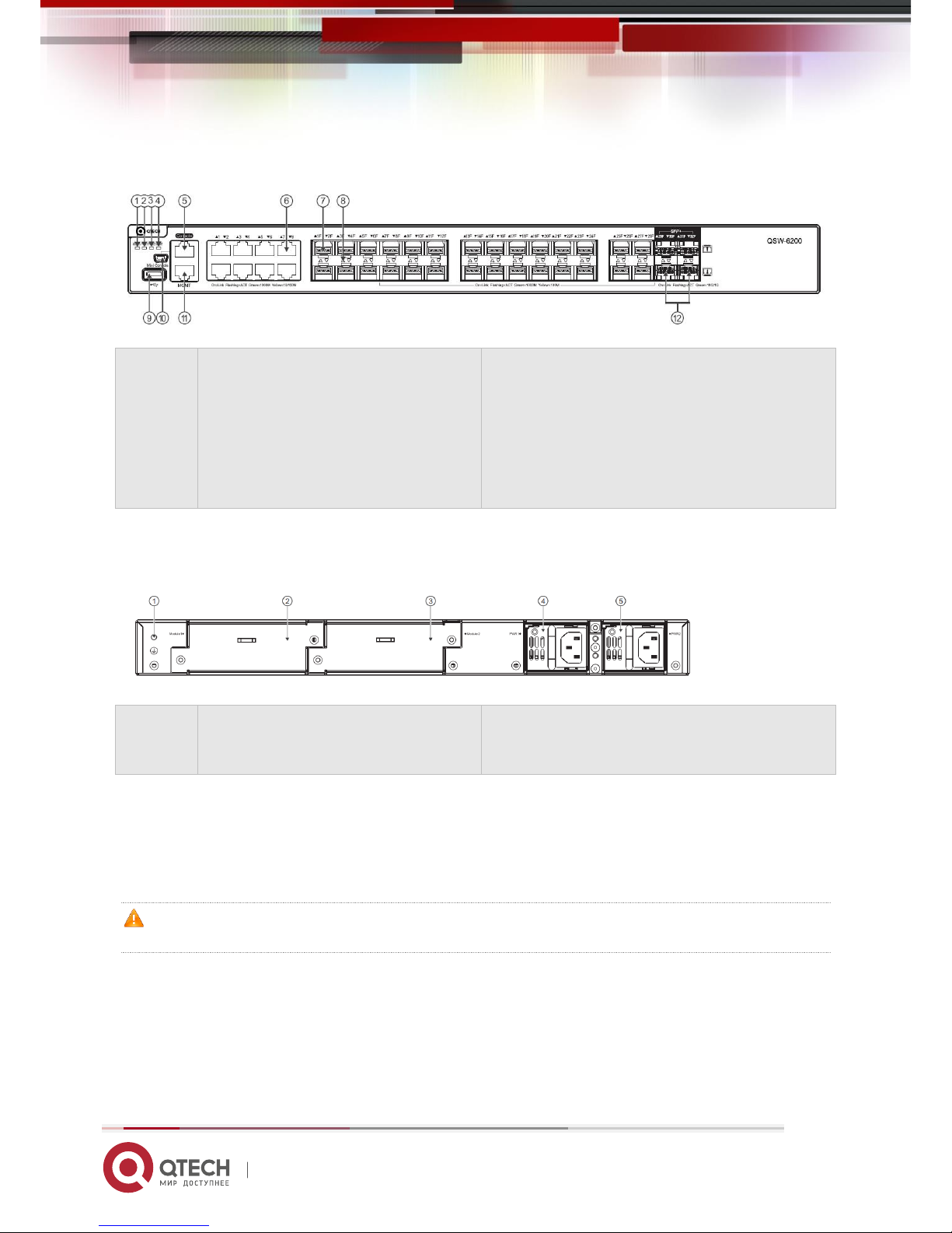
Figure 1-2 Front Panel of QSW-6200-32T
Note:
1. System status LED
2. Power status LED (PWR1)
3. Power status LED (PWR2)
4. MGMT port status LED
5. Console port
6. 10/100/1000 Base-T auto-sensing Ethernet
port
7. Switch port status LED
8. USB port
9. Mini USB port
10. MGMT port
11. GE SFP port
13. 10GE SFP+ port
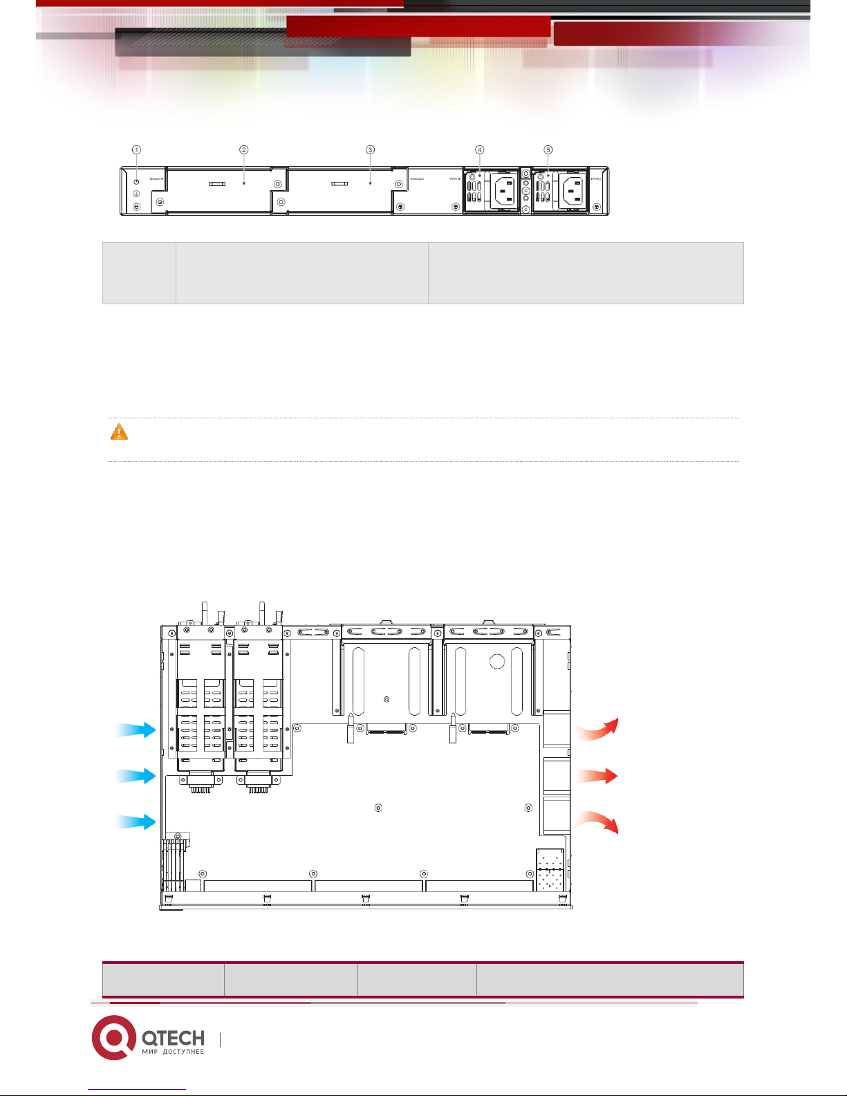
Back Panel
Figure 1-3 Back Panel of QSW-6200-32T
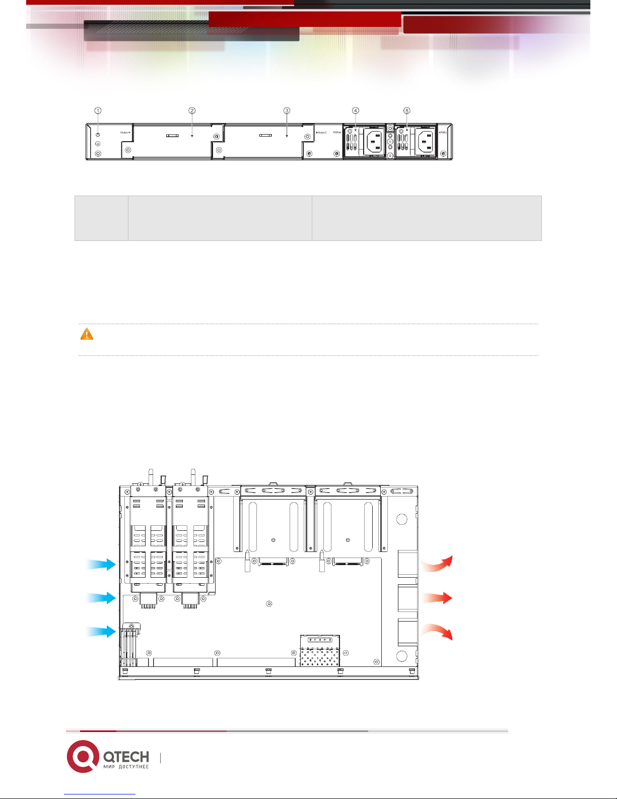
QSW-6200 Series Switch Hardware Installation and Reference Guide 8
www.qtech.ru
Note:
1. Grounding connector
2. Expansion module slot 1
3. Expansion module slot 2
4. Power module slot 1
5. Power module slot 2
Power Supply
QSW-6200-32T supports 2 power modules. For details, see the section “Power Modules”.
Dual-power input: The switch can be powered by one power module, or two power modules. When both two modules are
available, the switch is powered in current sharing mode.
When the switch is powered by the dual-power modules, if the system working power is greater than the capacity of
single power module, power redundancy cannot work; if one power module fails, the switch system will be affected.
Heat Dissipation
The QSW-6200-32T is designed with left and right fans for heat dissipation, thereby ensuring the normal function of the
device in the specified environment. Maintain a minimum clearance of 10cm around the chassis to allow air circulation.
Figure 1-4 Flow Scheme of Heat Dissipation
LED
QSW-6200 Series Switch Hardware Installation and Reference Guide 9
www.qtech.ru
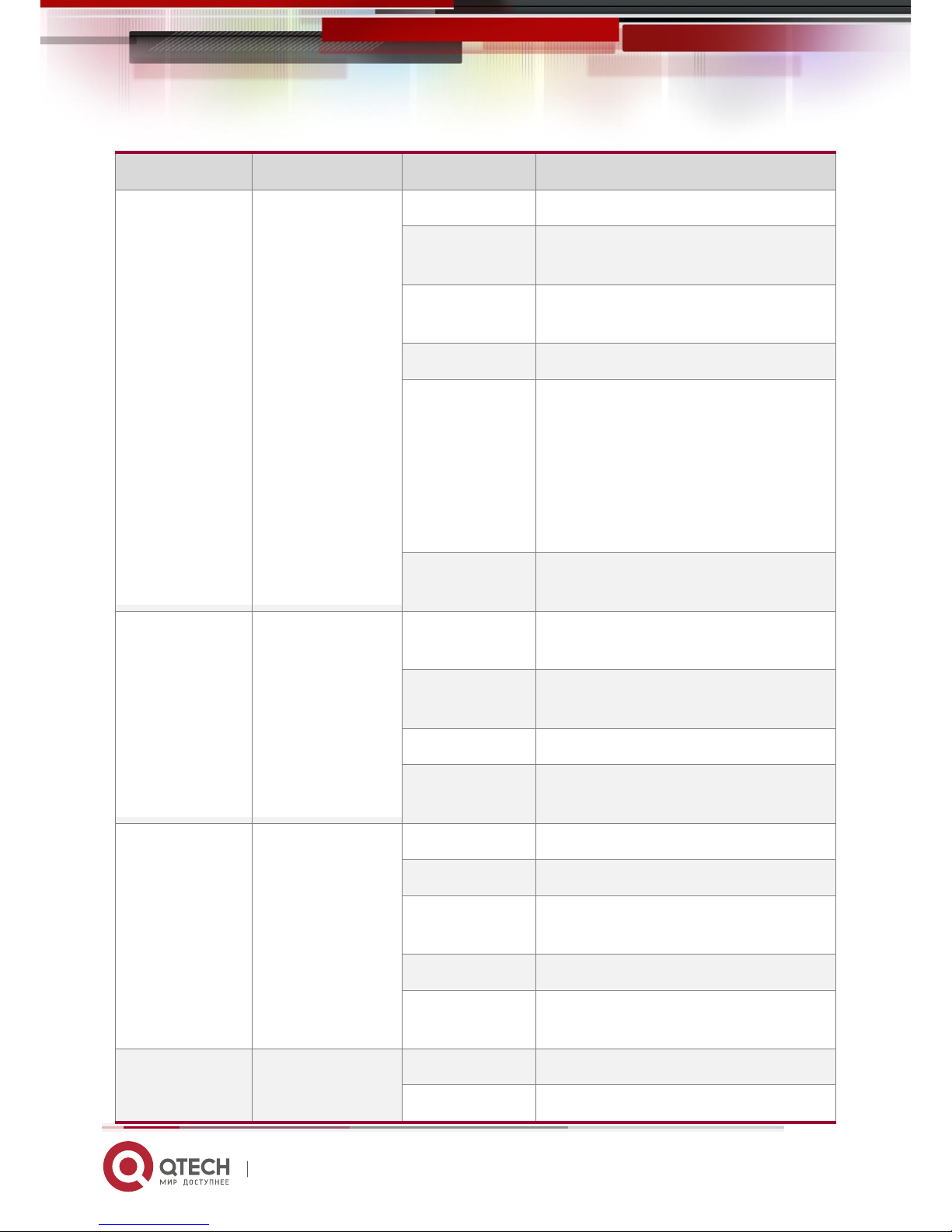
LED
Panel Identification
State
Meaning
System status LED
Status
Off
The switch is not receiving power.
Blinking green
(3 Hz)
The switch is being initialized with 3Hz blinking.
Continuous blinking indicates errors.
Blinking green
(10Hz)
Supports remote on/off to locate the switch.
Solid green
The switch is operational.
Solid yellow
Temperature alarm:
1. Temperature of inlet/outlet air exceeds the
normal operating temperature range.
2. The power supplies cannot support the whole
system.
Check the working environment of the switch and
power supplies immediately.
Solid red
The switch is faulty. For details, see the chapter
“Troubleshooting”.
Power status LED
PWR1/PWR2
Off
The power module is not in place or not receiving
power.
Solid green
The power module is connected and can supply
power.
Solid yellow
The power model is identified but not recognized.
Solid red
The redundant power is faulty or the AC power
cord is not connected.
MGMT port status
LED
MGMT
Off
The port is not connected.
Solid green
The port is connected at 1000 Mbps.
Blinking green
The port is receiving or transmitting traffic at
1000 Mbps.
Solid yellow
The port is connected at 10/100 Mbps.
Blinking yellow
The port is receiving or transmitting traffic at
10/100 Mbps.
10GE SFP+ port
status LED
29F-32F
Off
The port is not connected.
Solid green
The port is connected at 1/10 Gbps.
QSW-6200 Series Switch Hardware Installation and Reference Guide 10
www.qtech.ru
Blinking green
The port is receiving or transmitting traffic at 1/10
Gbps.
GE SFP port status
LED
25F-28F
Off
The port is not connected.
Solid green
The port is connected at 1000 Mbps.
Blinking green
The port is receiving or transmitting traffic at
1000 Mbps.
Solid yellow
The port is connected at 100 Mbps.
Blinking yellow
The port is receiving or transmitting traffic at 100
Mbps.
10/100/1000Base-T
auto-sensing
Ethernet port status
LED
1-28
Off
The port is not connected.
Solid green
The port is connected at 1000 Mbps.
Blinking green
The port is receiving or transmitting traffic at
1000 Mbps.
Solid yellow
The port is connected at 10/100 Mbps.
Blinking yellow
The port is receiving or transmitting traffic at
10/100 Mbps.
1.2 QSW-6200-52T
Technical Specifications
Model
QSW-6200-52T
Expansion Module
Slot
2 slots
Power Module
Slot
2 slots
AC input
Rated voltage: 100V to 240V
Maximum voltage: 90V to 264V
Frequency : 50/60 Hz
Rated current per input: 2A
HVDC input
Rated voltage: 120V to 340V

QSW-6200 Series Switch Hardware Installation and Reference Guide 11
www.qtech.ru
Maximum voltage: 110V to 380V
Rated current per input: 2A
DC input:
Rated voltage: -36V to -72V
Rated current per input: 3.15A
SFP Port
Not supported
SFP+ Port
10GBase-R
1000Base-X
Power
Consumption
≤45W (without expansion modules)
Temperature
Operating temperature: 0 ºC to 50ºC
Storage temperature: -40 ºC to 70ºC
Humidity
Operating humidity: 10% to 90% RH
Storage humidity: 5% to 95% RH
Fan
Speed adjustment and fault alarm
Temperature
Alarm
Supported
Dimensions
(W x D x H)
440 mm x 300 mm x 44 mm
Weight
4.2 kg
Product Appearance
The QSW-6200-52T Ethernet switch provides 48 10/100/1000Base-T Ethernet ports, 4 10GE SFP+ ports, 1 MGMT port,
1 USB port, 1 Mini USB port, and 1 Console port on the front panel, as well as 2 power module slots and 2 expansion
module slots on the back panel (The Console and Mini USB ports are a combo Console port. When they are connected
meanwhile, the Mini USB port takes the precedence).
QSW-6200 Series Switch Hardware Installation and Reference Guide 12
www.qtech.ru
Figure 1-5 Appearance of QSW-6200-52T
Front Panel
Figure 1-6 Front Panel of QSW-6200-52T
Note:
1. System status LED
2. Power status LED (PWR1)
3. Power status LED (PWR1)
4. MGMT port status LED
5. Console port
6. 10/100/1000Base-T auto-sensing Ethernet
port
7. Switch port status LED
8. USB port
9. Mini USB port
10. MGMT port
11. 10GE SFP+ port
Back Panel
Figure 1-7 Back Panel of QSW-6200-52T
QSW-6200 Series Switch Hardware Installation and Reference Guide 13
www.qtech.ru
Note:
1. Grounding connector
2. Expansion module slot 1
3. Expansion module slot 2
4. Power module slot 1
5. Power module slot 2
Power Supply
The QSW-6200-52T supports two power modules. For details, see the section “Power Modules”.
Dual-power input: The switch can be powered by one power module, or two power modules. When both two modules are
available, the switch is powered in current sharing mode.
When the switch is powered by the dual-power modules, if the system working power is greater than the capacity of
single power module, power redundancy cannot work; if one power module fails, the switch system will be affected.
Heat Dissipation
QSW-6200-52T adopts left and right fans for heat dissipation, thereby ensuring the normal function of the device in the
specified environment. Sufficient space (10 cm distance from both sides and the back panel of the cabinet) should be
reserved around the cabinet to allow air circulation.
Figure 1-8 Flow Scheme of Heat Dissipation
LED
LED
Panel Identification
State
Meaning

QSW-6200 Series Switch Hardware Installation and Reference Guide 14
www.qtech.ru
System status LED
Status
Off
The switch is not receiving power.
Blinking green
(3 Hz)
The switch is being initialized with 3Hz blinking.
Continuous blinking indicates errors.
Blinking green
(10Hz)
Supports remote on/off to locate the switch.
Solid green
The switch is operational.
Solid yellow
Temperature alarm:
1. Temperature of inlet/outlet air exceeds the
normal operating temperature range.
2. The power supplies cannot support the whole
system.
Check the working environment of the switch and
power supplies immediately.
Solid red
The switch is faulty. For details, see the chapter
“Troubleshooting”.
Power status LED
PWR1/PWR2
Off
The power module is not in place or not receiving
power.
Solid green
The power module is connected and can supply
power.
Solid red
The redundant power is faulty or the AC power
cord is not connected.
MGMT port status
LED
MGMT
Off
The port is not connected.
Solid green
The port is connected at 1000 Mbps.
Blinking green
The port is receiving or transmitting traffic at
1000 Mbps.
Solid yellow
The port is connected at 10/100 Mbps.
Blinking yellow
The port is receiving or transmitting traffic at
10/100 Mbps.
10GE SFP+ port
status LED
49F-52F
Off
The port is not connected.
Solid green
The port is connected at 1/10 Gbps.
Blinking green
The port is receiving or transmitting traffic at 1/10

QSW-6200 Series Switch Hardware Installation and Reference Guide 15
www.qtech.ru
Gbps.
10/100/1000Base-T
auto-sensing
Ethernet port status
LED
1-48
Off
The port is not connected.
Solid green
The port is connected at 1000 Mbps.
Blinking green
The port is receiving or transmitting traffic at
1000 Mbps.
Solid yellow
The port is connected at 10/100 Mbps.
Blinking yellow
The port is receiving or transmitting traffic at
10/100 Mbps.
1.3 QSW-6200-32F
Technical Specifications
Model
QSW-6200-32F
Expansion Module
Slot
2 slots
Power Module
Slot
2 slots
AC input:
Rated voltage: 100V to 240V
Maximum voltage: 90V to 264V
Frequency: 50/60 Hz
Rated current per input: 2 A
HVDC input:
Rated voltage: 120V to 340V
Maximum voltage: 110V to 380V
Rated current per input: 2A
DC input:
Rated voltage: -36V to -72V
Rated current per input: 3.15A
SFP Port
100Base-X
1000Base-X
SFP+ Port
10GBbase-R
QSW-6200 Series Switch Hardware Installation and Reference Guide 16
www.qtech.ru
1000Base-X
Power
Consumption
≤55W (without expansion modules)
Temperature
Operating temperature: 0 ºC to 50ºC
Storage temperature: -40ºC to 70ºC
Humidity
Operating humidity: 10% to 90% RH
Storage humidity: 5% to 95% RH
Fan
Speed adjustment and fault alarm
Temperature
Alarm
Supported
Dimensions
(W x D x H)
440 mm x 300 mm x 44 mm
Weight
4.2kg
Product Appearance
The QSW-6200-32F Ethernet switch provides 28 GE SFP ports, 8 10/100/1000Base-T GE combo ports, 4 10GE SFP+
ports, 1 MGMT port, 1 USB port, 1 Mini USB port, and 1 Console port on the front panel, as well as 2 power module slots
and 2 expansion module slots on the back panel.
Figure 1-9 Appearance of QSW-6200-32F
Front Panel
QSW-6200 Series Switch Hardware Installation and Reference Guide 17
www.qtech.ru
Figure 1-10 Front Panel of QSW-6200-32F
Note:
1. System status LED
2. Power status LED (PWR1)
3. Power status LED (PWR2)
4. MGMT port status LED
5. Console port
6. 10/100/1000Base-T auto-sensing Ethernet
port
7. GE SFP port
8. Switch port status LED
9. USB port
10.Mini USB port
11. MGMT port
12.10GE SFP+ port
Back Panel
Figure 1-11 Back Panel of QSW-6200-32F
Note:
1. Grounding connector
2. Expansion module slot 1
3. Expansion module slot 2
4. Power module slot 1
5. Power module slot 2
Power Supply
The QSW-6200-32F supports two power modules. For details, see the section “Power Modules”.
Dual-power input: The switch can be powered by one power module, or two power modules. When both two modules are
available, the switch is powered in current sharing mode.
When the switch is powered by the dual-power modules, if the system working power is greater than the capacity of
single power module, power redundancy cannot work; if one power module fails, the switch system will be affected.
Heat Dissipation
The QSW-6200-32F is designed with left and right fans for heat dissipation, thereby ensuring the normal function of the
device in the specified environment. Sufficient space (10 cm distance from both sides and the back panel of the cabinet)
should be reserved to allow air circulation.

QSW-6200 Series Switch Hardware Installation and Reference Guide 18
www.qtech.ru
Figure 1-12 Flow Scheme of Heat Dissipation
LED
LED
Panel Identification
State
Meaning
System status LED
Status
Off
The switch is not receiving power.
Blinking green
(3 Hz)
The switch is being initialized with 3Hz blinking.
Continuous blinking indicates errors.
Blinking green
(10Hz)
Supports remote on/off to locate the switch.
Solid green
The switch is operational.
Solid yellow
Temperature alarm:
1. Temperature of inlet/outlet air exceeds the
normal operating temperature range.
2. The power supplies cannot support the whole
system.
Check the working environment of the switch and
power supplies immediately.
Solid red
The switch is faulty. For details, see the chapter
“Troubleshooting”.
Power status LED
PWR1/PWR2
Off
The power module is not in place or not receiving
power.

QSW-6200 Series Switch Hardware Installation and Reference Guide 19
www.qtech.ru
Solid green
The power module is in place and can supply
power.
Solid red
The redundant power is faulty or the AC power
cord is not connected.
MGMT port status
LED
MGMT
Off
The port is not connected.
Solid green
The port is connected at 1000 Mbps.
Blinking green
The port is receiving or transmitting traffic at
1000 Mbps.
Solid yellow
The port is connected at 10/100 Mbps.
Blinking yellow
The port is receiving or transmitting traffic at
10/100 Mbps.
10GE SFP+ port
status LED
29F-32F
Off
The port is not connected.
Solid green
The port is connected at 1/10 Gbps.
Blinking green
The port is receiving or transmitting traffic at 1/10
Gbps.
GE SFP port status
LED
1F-28F
Off
The port is not connected.
Solid green
The port is connected at 1000 Mbps.
Blinking green
The port is receiving or transmitting traffic at
1000 Mbps.
Solid yellow
The port is connected at 100 Mbps.
Blinking yellow
The port is receiving or transmitting traffic at 100
Mbps.
10/100/1000Base-T
auto-sensing
Ethernet port status
LED
1-8
Off
The port is not connected.
Solid green
The port is connected at 1000 Mbps.
Blinking green
The port is receiving or transmitting traffic at
1000 Mbps.
Solid yellow
The port is connected at 10/100 Mbps.
Blinking yellow
The port is receiving or transmitting traffic at
10/100 Mbps.

QSW-6200 Series Switch Hardware Installation and Reference Guide 20
www.qtech.ru
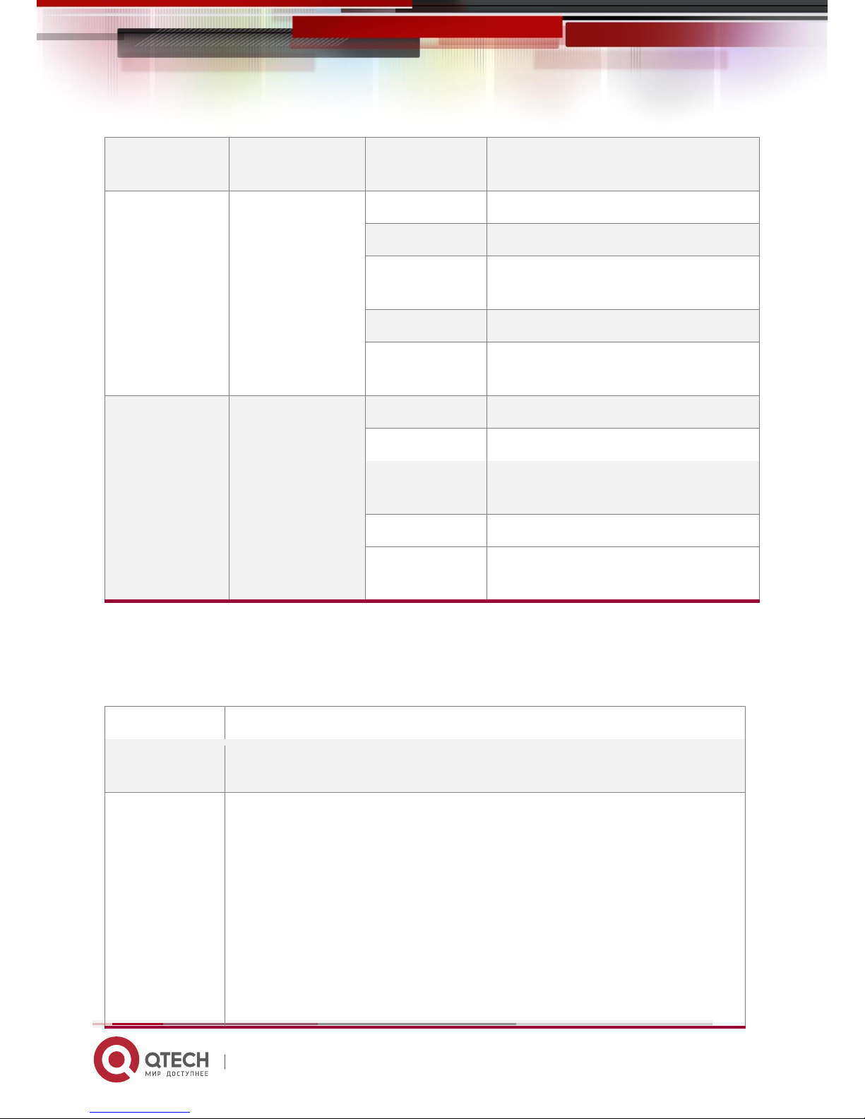
1.4 Expansion Modules
The QSW-6200-52T series switches support the following modules: QSW-M-6200-4SFP+ and QSW-M-6200-STACK.
QSW-M-6200-4SFP+ is only supported on the expansion module slot 1 of QSW-6200-52T.
The QSW-6200-32T and QSW-6200-32F series switches support the QSW-M-6200-STACK module.
Module
Description
External port
QSW-M-6200-4SFP+
4-port 10GE optical module
4 SFP+ ports
QSW-M-6200-STACK
1-port stack module
1 QSFP+ port
For the detailed description about those two modules, see
Switch Extension Module Manual
.
1.5 Power Modules
At present, the QSW-6200 series switches support the swappable QSW-M-6200-PWR and QSW-M-6200-PWR2 power
module. The QSW-M-6200-PWR power module provides AC (HVDC) input and DC output, 12V voltage output and up to
70W power output to the switch. And the QSW-M-6200-PWR2 power module provides DC input, 12V voltage output and
up to 70W power output to the switch.
Only the QSW-M-6200-PWR and QSW-M-6200-PWR2 power module is supported. Do not apply other power
modules.
QSW-M-6200-PWR
Specification
Model
QSW-M-6200-PWR (AC input)
QSW-M-6200-PWR (HVDC input)
Rated Voltage
100V to 240V
50/60 Hz
120V to 340V
Maximum Voltage
90V to 264V
47/63Hz
110V to 380V
Input Current
2A
Output Voltage
12V
Max Current Output
5.83A
Max Power Output
70W

QSW-6200 Series Switch Hardware Installation and Reference Guide 21
www.qtech.ru
Dimensions
(L x W x H)
156 mm x 50.5 mm x 38 mm
Weight
≈0.395 kg
Temperature
Operating temperature: -10℃ to 50℃
Storage temperature: -40℃ to 70℃
Humidity
Operating humidity: 10% to 90%
Storage humidity: 5% to 95%
Altitude
Operating altitude: 0 m to 5,000 m
Storage altitude: 0 m to 10,000 m
Features
Feature
Description
Conformal Coating
Protects circuits against moisture, frog, mould, electrical shock and leakage, and so on.
Protection
Provides protection over over-voltage/current input/output, short-circuit output and so
on.
I2C Communication
Allows the host to communicate with the power module by I2C.
Power Supply Redundancy
Supports dual power modules to cooperate in parallel, enabling PE with 1+1
redundancy and redundant power supplies with current sharing.
Hot Swapping
Supports to disconnect one redundant power module from the outside power supply
system, plug and unplug power modules while the device is powered on.
Power Supply Alarm
Alarms power supply faults through the power status LED.
LED
LED
Panel Identification
State
Meaning
Status LED
DC OK
Off
There is no power input or input under voltage.
Solid green
The module is operational.

QSW-6200 Series Switch Hardware Installation and Reference Guide 22
www.qtech.ru
QSW-M-6200-PWR2
Specification
Model
QSW-M-6200-PWR2 (DC input)
Rated Voltage
-36V to -72V
Input Current
3.15A
Output Voltage
12V
Max Current Output
5.83A
Max Power Output
70W
Dimensions
(L x W x H)
156mm x 50.5mm x 38mm
Weight
0.385 kg
Temperature
Operating temperature: -10℃ to +50℃
Storage temperature: -40℃ to +70℃
Humidity
Operating humidity: 10% to 90%
Storage humidity: 5% to 95%
Altitude
Operating altitude: 0 m to 5,000 m
Storage altitude: 0 m to 10,000 m
Features
Feature
Description
Conformal Coating
Protects circuits against moisture, frog, mould, electrical shock and leakage, and so on.
Protection
Provides protection over over-voltage/current input/output, short-circuit output and so
on.
I2C Communication
Allows the host to communicate with the power module by I2C.
Power Supply Redundancy
Supports dual power modules to cooperate in parallel, enabling PE with 1+1
redundancy and redundant power supplies with current sharing.
Hot Swapping
Supports to disconnect one redundant power module from the outside power supply
system, plug and unplug power modules while the device is powered on.
Power Supply Alarm
Alarms power supply faults through the power status LED.

QSW-6200 Series Switch Hardware Installation and Reference Guide 23
www.qtech.ru
LED
LED
Panel Identification
State
Meaning
Status LED
OUT
Off
There is no power input or input under voltage.
Solid green
The module is operational.

QSW-6200 Series Switch Hardware Installation and Reference Guide 24
www.qtech.ru
2 Preparation before Installation
2.1 Safety Suggestions
To avoid personal injury and equipment damage, please carefully read the safety suggestions before you install the
QSW-6200 series.
The following safety suggestions may not cover all possible dangers.
2.1.1 Installation
Keep the chassis clean and free from dust.
Do not place the equipment in a passage.
Do not wear loose clothes or any other things that may be caught by the chassis during installation and
maintenance.
Turn off all power supplies and remove the power sockets and cables before dismantling the cabinet.
2.1.2 Movement
Do not frequently move the device.
While moving the device, keep its balance and avoid your legs, feet and back from being hurt.
Before moving the device, turn off all power supplies and dismantle all power modules.
2.1.3 Electricity
Observe local regulations and specifications when performing electric operations. Relevant operators must be
qualified.
Carefully check any potential danger in the working area, such as ungrounded power supply, unreliable
grounding of the power supply, and damp/wet ground or floor.
Find out the location of the emergency power supply switch in the room before installation. First cut off the power
supply in the case of an accident.
Do no maintain the switch that is powered-on alone.
Make sure that the power is turned off when necessary.
Do not place the equipment in a damp place. Do not let any liquid enter the chassis.
Any non-standard and impropriate electric operations may cause an accident such as a fire or electrical shock, thus
causing severe even fatal damage to human bodies and equipment.
Direct or indirect touch through a wet object on high-voltage and commercial electricity may bring a fatal danger.

QSW-6200 Series Switch Hardware Installation and Reference Guide 25
www.qtech.ru
2.1.4 ESD
To prevent Electronic Static Discharge (ESD), pay attention to the following:
Connect the device's circuit to the ground.
Clear up the dust.
Maintain the proper humidity.
2.1.5 Laser
Among the modules supported by the QSW-6200 series, many are Class I laser products. Therefore, pay attention to the
following when using them:
When a fiber transceiver works, ensure that the port has been connected with an optical fiber or is covered with a
dust cap, to keep out dust and avoid burning your eyes.
Do not stare into the optical ports.
Do not approach or stare into any optical port, as this may cause permanent damage to your eyes.
2.2 Installation Site Requirements
The QSW-6200 series must be used indoors. To ensure its functioning and prolong its service life, the installation site
must meet the following requirements.
The machine room should be at least 5km away from the heavy pollution source such as the smelter, coal mine
and thermal power plant, 3.7km away from the medium pollution source such as the chemical industry, rubber
industry and electroplating industry, and 2km away from the light pollution source such as the food manufacturer
and leather plant. If the pollution source is unavoidable, the machine room should be located on the windward
side of the pollution source perennially with advanced protection.
The machine room should be at least 3.7km away from the sea or salt lake. Otherwise, the machine room must
be sealed, with air conditioner installed for temperature control. Saline soil cannot be used for construction.
Otherwise, you should select devices with advanced protection against severe environment.
Do not build the machine room in the proximity of livestock farms. Otherwise, the machine room should be
located on the windward side of the pollution source perennially. The previous livestock house or fertilizer
warehouse cannot be used as the machine room.
The machine room should be firm enough to withstand severe weather conditions such as windstorm and heavy
rain as well as away from dust. If the dust is unavoidable, keep the door and window away from the pollution
source.
The machine room should be away from the residential area. Otherwise, the machine room should meet the
construction standard in terms of noise.
Make sure the air vent of the machine room is away from the sewage pipe, septic tank, and sewage treatment
tank. Keep the machine room under positive pressure to prevent corrosive gas from entering the machine room
to corrode components and circuit boards. Keep the machine room away from industrial boiler and heating boiler.

QSW-6200 Series Switch Hardware Installation and Reference Guide 26
www.qtech.ru
The machine room had better be on the second floor or above. Otherwise, the machine room floor should be
600mm higher than the highest flood level ever recorded.
Make sure there are no cracks or holes in the wall and floor. If there are cable entries in the wall or window, take
proper sealing measures. Ensure that the wall is flat, wear-resistant, and dust-free, which should be up to the
standard for flame retarding, soundproofing, heat absorption, dust reduction, and electromagnetic shielding.
Keep the door and the window closed to make the machine room sealed.
The steel door is recommended for soundproofing.
Sulfur-containing materials are forbidden.
Pay attention to the location of the air conditioner. Keep the air conditioner from blowing wind straight toward the
device or blowing water drops from the window or air vent toward the device.
2.2.1 Ventilation
QSW-6200 should be placed at least 10 cm away from surrounding walls to effective ventilation and heat dissipation.
Cables should be bunched or put on the cable frame after being connected in order to prevent blocking the air intake.
2.2.2 Temperature and Humidity
The temperature and humidity in the room must be stable to ensure the device's proper functioning and prolong its service
life.
Continuous improper temperature and humidity will cause damage to the device.
High relative humidity will reduce the insulation of insulation materials and cause electric leakage. Sometimes it may lead
to changes in the mechanical characters of materials and rust metal components.
Low relative humidity will dry the insulation sheets and generate static electricity, which will damage the electric circuits of
the device.
High temperature will large affect the device's reliability, shorten its service life and accelerate its aging.
Temperature and humidity requirements of the QSW-6200 series are as follows:
Temperature
Relative Humidity
0 ºC to 50ºC
10% to 90%
The working temperature and humidity are measured 1.5 m above the ground and 0.4 m away from the front plat and
when the chassis’ front and rear protective plates are removed.
2.2.3 Cleanness
Dust poses the top threat to the running of the equipment. The indoor dust falling on the equipment may be adhered by
the static electricity, causing bad contact of the metallic joint. Such electrostatic adherence may occur more easily when
the relative humidity is low, not only affecting the use life of the equipment, but also causing communication faults. The
following table shows the requirements for the dust content and granularity in the equipment room.

QSW-6200 Series Switch Hardware Installation and Reference Guide 27
www.qtech.ru
Max Dust Diameter (μm)
0.5
1
3
5
Dust Particle (Particles/m3)
1.4 x 10
7 x 10
2.4 x 10
1.3 x 10
Apart from dust, the salt, acid and sulfide in the air in the equipment room must also meet strict requirements; as such
poisonous substances may accelerate the corrosion of the metal and the aging of some parts. The equipment room
should be protected from the intrusion of harmful gases (for example, SO2, H2S, NO2 and Cl2), whose requirements are
listed in the following table.
Gas
Average (mg/m3)
Maximum (mg/m3)
SO2
0.2
1.5
H2S
0.006
0.03
NO2
0.04
0.15
NH3
0.05
0.15
Cl2
0.01
0.3
2.2.4 Grounding
A good grounding system is the basis for the stable and reliable operation of the QSW-6200 series, preventing lightning
stroke and resisting interference. Please carefully check the grounding conditions on the installation site according to the
grounding requirements, and perform grounding operations properly as required.
The correct connection of grounding lines guarantees the lighting and interference resistance of switches and must
be performed with precision.
Safety Grounding
The equipment using AC power supply must be grounded by using the yellow/green safety grounding cable. Otherwise,
when the insulating resistance decreases the power supply and the enclosure in the equipment, electric shock may occur.
Lightning Grounding
The lightning protection system of a facility is an independent system that consists of the lightning rod, downlead
conductor and the connector to the grounding system, which usually shares the power reference ground and yellow/green
safety cable ground. The lightning discharge ground is for the facility only, but unnecessary for equipment.
EMC Grounding
The grounding required for EMC design includes shielding grounding, filter grounding, noise and interference suppression,
and level reference. All the above constitute the comprehensive grounding requirements. The grounding resistance
should be less than 1Ω. The QSW-6200 back panel has one grounding connector.
Figure 2-1 Grounding of the QSW-6200

QSW-6200 Series Switch Hardware Installation and Reference Guide 28
www.qtech.ru
2.2.5 Lightning Resistance
When the AC power cable is imported outdoors and directly connected to the power port of the switch, lightning
preventing wires should be adopted to prevent the switch from being hit by lightning shocks. The lightning preventing
wires can be fixed on the cabinet, work station, or the equipment room’s wall through line buckles and screws. In
applications, the AC current first enters the lightning preventing wires and then the switch.
The lightning preventing wires are not provided and should be purchased by users as required. For the usage of
lightning preventing wires, refer to their manuals.
2.2.6 EMI
All kinds of interference, from inside or outside of the device or application system, create impacts on the device by
transmission of capacity coupling, inductance coupling and electromagnetic waves.
Electromagnetic interference can be divided into two categories by transmission types, namely i.e. radiated interference
and conducted interference.
Power, normally RF power, transmitted from a device through space to a sensor is called radiated interference. The origin
of the interference source can either be part of or a unit separated electrically from the interfered system. Conducted
interference is transmitted through magnetic wires or signal cables from the source origin to sensors. Generally,
conducted interference affects the power supply of a device and can be controlled by a wave filter. Given that radiated
interference can interrupt any signal paths of the device, it is difficult to shield the device from such interference.
The AC power supplying system is the TN system. The single-phase three-wire socket with protecting grounding
must be used as the socket for the power supply to enable the device’s upper filter circuit to effective filter the
power interface.
The switch should be far from high-power radio transmitting stations, radar stations and high-frequency and
large-current devices.
Electromagnetic shielding methods should be applied when necessary, such as using the shielded cable as the
interface cable.
Cables must be connected to interfaces inside the room to prevent damage to the device’s signal ports caused

QSW-6200 Series Switch Hardware Installation and Reference Guide 29
www.qtech.ru
by over-voltage and over-current generated by thunder and lightning.
2.3 Precautions for Fiber Connections
Before you connect the fibers, check that the optical connector type and fiber type match the optical interface type used. In
addition, pay attention to the Tx and Rx directions of the fiber. The Tx end of this device should be connected to the Rx
end of the peer device, and the Rx end of this device to the Tx end of the peer device.
2.4 Installation Tools
List of Installation Tools
Common Tools
Phillips screwdriver, flat-head screwdriver, related electric cables and optical cables,
bolts, diagonal pliers, straps
Special Tools
Anti-static tools
Meters
Multimeter
QSW-6200 is not provided with a tool kit. Please prepare tools on your own.

QSW-6200 Series Switch Hardware Installation and Reference Guide 30
www.qtech.ru
3 Product Installation
Please ensure that you have carefully read Chapter 2 and make sure that the requirements set forth in Chapter 2
have been met.
3.1 Installation Flowchart
Mount the switch to the rack
Connect the system grounding
Connect the power supply
Connect interface cables
Bundle the power cables or optical fibers
Installation check
3.2 Pre-installation Confirmation
Before installation, please confirm the following points:
Whether sufficient airflow is available for the switch
Whether the requirements of the switch for temperature and humidity are met
Whether power cables are already laid out and whether the requirements of electrical current are met
Whether related network cables are already laid out
3.3 Installing the Switch
Precautions
During installation, note the following points:
Connect the power cables of different colors to the corresponding grounding posts.
Ensure that the connected power cables have sound contact.
Do not place heavy items on the switch.
Reserve a spacing of at least 10 cm around the chassis for good ventilation. Do not stack the devices.
The switch should be located far away from the large power radio launch pad, radar launch pad, and
high-frequency large-current devices. If necessary, electromagnetic shielding should be adopted. For example,
use interface cables to shield cables.
Interface cables should be laid inside the equipment room. Outdoor cabling is prohibited, avoiding damages to

QSW-6200 Series Switch Hardware Installation and Reference Guide 31
www.qtech.ru
device signal interfaces caused by over-voltage or over-current of lightning.
3.3.1 Mounting the Switch in a Standard 19-inch Rack
The QSW-6200 series switches follow the EIA standard dimensions and can be installed in 19-inch rack. During the
installation, place the front panel of the switch to the rack. For safety purposes, screw up the distributed screws as shown
in the 3-1.
Figure 3-1 Attaching the Mounting Bracket to the Switch
3.3.2 Mounting the Switch on the Wall
The QSW-6200 series switches can be mounted on a wall with the supplied mounting brackets, as shown in Figure 3-2.
Figure 3-2 Attaching the Mounting Brackets to the Switch for Wall-Mounting
3.3.3 Mounting the Switch on a Table
For often, users may not have a 19-inch rack. Thus, it is common to mount the switch on the workbench with 2 simple
steps:

QSW-6200 Series Switch Hardware Installation and Reference Guide 32
www.qtech.ru
Attach the four rubber feet to the recessed areas on the bottom of the switch.
Place the switch on the table and keep good ventilation.
3.4 Installing and Removing the Expansion Modules
Wear anti-static gloves before the following operations.
3.5 Installing and Removing the Power Modules
Please wear anti-static gloves equipment.
Installing an QSW-M-6200-PWR Power Module
Step 1: Take a new power module out of the package and confirm the input mode and the input parameters of the power
module match the requirements.
Step 2: Remove the power baffle and take the plane printed with power information as the top panel of the power module.
Hold the handle of the power module with one hand, and hold the end of the power module with the other hand. Insert it
into the chassis along the guide rail uprightly and slowly until a click is heard, and make sure that it is in good contact with
the power slot.
Figure 3-5 Installing a Power Module
Insert the power module smoothly. Please pay attention to the direction of the power panel to avoid wrong insertion.
If it is difficult or even impossible to insert the module, pull out the module, make sure the expansion module and
guide rail are well aligned, and then insert the module again.
Removing an QSW-M-6200-PWR Power Module
Step 1: Press the plug of the power module, Hold on to the module handle with one hand to pull out part of the module,
hold the bottom of it with the other hand, and pull out the power module uprightly and slowly.
Step 2: Install a baffle in the power module slot and put the removed power module into its package.
Figure 3-4 Removing a Power Module

QSW-6200 Series Switch Hardware Installation and Reference Guide 33
www.qtech.ru
Remove the power module uprightly and slowly.
Install a baffle in the location where the power module is removed to ensure the normal ventilation and dissipation
and avoid the dust in the chassis.
Installing an QSW-M-6200-PWR2 Power Module
Step 1: Take a new power module out of the package and confirm the input mode and the input parameters of the power
module match the requirements.
Step 2: Remove the power baffle and take the plane printed with power information as the top panel of the power module.
Hold the handle of the power module with one hand, and hold the end of the power module with the other hand. Insert it
into the chassis along the guide rail uprightly and slowly until a click is heard, and make sure that it is in good contact with
the power slot. The three screws are the input terminals of the DC power module. Remove the screws, and then put the
ends of power cables in place before driving the screws back. From left to right, cables are blue, red and yellow-green.
Then, remember to cover the terminals with protective caps.
Step 3: Connect the other ends of power cables to the DC panelboard: connect the blue one to the -48VDC terminal, the
red one to -48VGND, and the yellow-green one to PGND.
Figure 3-7 Installing a Power Module
Figure 3-7 Connecting Power Cables to the DC Panelboard

QSW-6200 Series Switch Hardware Installation and Reference Guide 34
www.qtech.ru
Insert the power module smoothly. Please pay attention to the direction of the power panel to avoid wrong insertion.
If it is difficult or even impossible to insert the module, pull out the module, make sure the expansion module and
guide rail are well aligned, and then insert the module again.
Removing an QSW-M-6200-PWR2 Power Module
Step 1: Press the plug of the power module, Hold on to the module handle with one hand to pull out part of the module,
hold the bottom of it with the other hand, and pull out the power module uprightly and slowly.
Step 2: Install a baffle in the power module slot and put the removed power module into its package.
Figure 3-9 Removing a Power Module
Remove the power module uprightly and slowly.
Install a baffle in the location where the power module is removed to ensure the normal ventilation and dissipation
and avoid the dust in the chassis.

QSW-6200 Series Switch Hardware Installation and Reference Guide 35
www.qtech.ru
3.6 Grounding the Switch
QSW-6200 has a PGND on the back panel. First connect the PGND to the grounding lug of the rack and then connect the
grounding lug to the grounding bar of the equipment room.
Precautions
The sectional area of the grounding wire should be determined according to the possible maximum current.
Cables of good conductor should be used.
Do not use bare wire.
The grounding electric resistance should be less than 1Ω.
To guarantee the security of the body and the device, the switch must be well-grounded. The grounding resistance
for combined grounding should be less than 1Ω.
The maintenance personnel shall check whether or not the AC socket powering the switch is well connected to the
building protective earth (PE). If not, the personnel shall connect the grounding lug of the AC socket with the PE by using
a grounding connector.
The AC socket shall be installed near the equipment and shall be easily used.
When installing the switch, make sure the grounding is connected first and disconnected last.
The cross-sectional area of PE conductor shall be at least 2.5 mm2 (12AWG).
3.7 Connecting the External Port Cables
Precautions
Correctly distinguish single-mode and multi-mode fibers and ports.
Avoid bends of small radius at the connector.
Steps
Step 1: Connect one end of the RJ45 connector to the Ethernet interface of the device board, and the other end to the
NMS or a control terminal.
Step 2: Insert the single-mode or multi-mode fiber into the appropriate interface according to the identification on the panel
of the module.
Step 3: Insert the twisted pair with the RJ45 port into the appropriate interface according to the identification on the panel
of the module. Distinguish the crossover cable and straight-through cable.

QSW-6200 Series Switch Hardware Installation and Reference Guide 36
www.qtech.ru
3.8 Bundling the Cables
Precautions
The power cables and other cables should be bundled in a pleasing way.
When you bundle fibers, make sure that the fibers at the connectors have natural bends or bends of large radius.
Do not bundle fibers and twisted pairs too tightly, as this may press hard the fibers and affect their service time
and transmission performance.
Steps
Bind the drooping part of the fibers and twisted pairs of each board, and lead them to both sides of the chassis for
convenience.
On the both sides of the chassis, fasten the fibers and twisted pairs to the cabinet cable management ring or
cabling chute.
For the power cables, you should bundle them closely along the bottom of the chassis, in a straight line wherever
possible.
3.9 Checking after Installation
Before checking the installation, switch off the power supply to avoid any personal injury or damage to the
component due to connection errors.
Check that the ground line is connected.
Check that the cables and power input cables are correctly connected.
Check that all interface cables are laid out inside the equipment room. In the case of external cabling, check that
the lightning resistance socket or network interface lightning protector is connected.
Check that sufficient airflow is available around the device (over 10 cm).

QSW-6200 Series Switch Hardware Installation and Reference Guide 37
www.qtech.ru
4 System Commissioning
4.1 Establishing the Configuration Environment
Establishing the Configuration Environment
Use the Console cable to connect the PC to the switch.
Figure 4-1 Configuration Environment
Connecting the Console Cable
The QSW-6200 series switches support the following connecting ways:
Step 1: Connect the serial & Console ports
Connect the DB-9 end of the Console cable to the serial port of the PC.
Connect the RJ45 end of the Console cable to the Console port of the switch.
Step 2: Connect the USB & Mini USB ports
Connect the USB end of the cable to the USB port of the PC.
Connect the Type-B Mini USB end of the cable to the Mini USB port of the switch.
QSW-6200 supports Mini USB Console combo by the Mini USB Console driver, which can be downloaded on the TI
website. If both the Mini USB port and Console port are connected, the default Console port is the former.
When the Mini USB port is connected to PCs, besides the Mini USB Console driver should be installed on PCs and
the cable connector is different, other configuration is the same as that of the serial port.

QSW-6200 Series Switch Hardware Installation and Reference Guide 38
www.qtech.ru
Setting Terminal Parameters
Step 1: Start the PC and run the terminal simulation program on the PC, such as Terminal on Windows 3.1 or
HyperTerminal on Windows 95/98/NT/2000/XP.
Step 2: Set terminal parameters. The parameters are as follows: baud rate 9600, data bit 8, parity check none, stop bit 1,
and flow control as none.
Choose Setup > Program > Attachment > Communication > Super Terminal.
Choose Cancel to display the following page.
Figure 4-2
Enter the name of the new connection and click OK to display the following page. Choose the series port used currently in
the column [use when connecting].
Figure 4-3

QSW-6200 Series Switch Hardware Installation and Reference Guide 39
www.qtech.ru
After choosing the series port, click OK to display the series port parameter setting page, set the baud rate at 9600, data
bit at 8, parity check as none, stop bit at 1 and flow control as none.
Figure 4-4
After setting the parameters, click OK to enter the super terminal page.
4.2 Power-on Startup
Checking before Power-on
The switch is fully grounded.
The power cable is correctly connected.
The power cable is buckled after connected.
The power supply voltage complies with the requirement of the switch.
The console cable is correctly connected; the terminal (can be a PC) used for configuration is already started; the
parameters are already configured.
Checking after Power-on (Recommended)
After power-on, you are recommended to perform the following checks to ensure the normal operation of
follow-up configurations.

QSW-6200 Series Switch Hardware Installation and Reference Guide 40
www.qtech.ru
Check that information is displayed on the terminal interface.
Check that the device LEDs are normal.

QSW-6200 Series Switch Hardware Installation and Reference Guide 41
www.qtech.ru
5 Monitoring and Maintenance
Monitoring LED
When the QSW-6200 is running, users can monitor the status of host and each module by inspecting corresponding
LEDs.
When the system status LED is red, it means the system has a fault, in which case you can determine and
eliminate the fault by viewing with the management software.
When the system status LED is yellow, it means the system temperature exceeds the alarm temperature,
affecting the system operation performance. However, the system can continue running. In this case, you can
determine and eliminate the fault by viewing with the management software.
When the system status LED is red or blinking, it indicates a failure, in which case you need to find out the cause,
and turn off the power when necessary.
When power status LED is yellow, it means that the power is not enough to support the host and expansion
modules, in which case you should apply RPS modules.
When the power status LED is red, check whether or not the power cable is in place and operational; if not
problem, it means the power supply is faulty, in which case you should replace it promptly.
When the LED of expansion modules is blinking or red, it means the expansion modules are faulty, in which case
you should plug and check the modules.
The fast green blinking (10Hz) state of the system status LED is used to locate a switch, which should be
distinguished from the slow blinking state (3Hz).
CLI Commands
The QSW-6200 allows you to monitor various system states by executing the appropriate CLI commands, including:
System working status
Port configuration and status
Working status of fans and power supplies
System temperature
QSW-6200 supports the Data Center Manageability Interface (DCMI) protocol.
For the configuration and functions, refer to the
Configuration Guide
.
5.1 Hardware Maintenance
Expansion Module Maintenance
If any fault occurs and an expansion module shall be replaced, remove it and install a new one according to the section
“Installing and Removing the Expansion Modules”.

QSW-6200 Series Switch Hardware Installation and Reference Guide 42
www.qtech.ru
Ventilation System Maintenance
The fan in the equipment responsible for heat dissipation is provided with the fault monitoring signals. When the
fan fails, a corresponding alarm will occur.
Replace the faulty fan with a qualified one.
Tighten the captive screws of the fan module.
Power Supply Maintenance
When the power supply fails, you only need to disconnect the power cable, unplug the power module, replace it with a
qualified one, and then connect the power cables tightly.
Replacing Lithium Battery
The built-in lithium batteries can support the real time clock of the QSW-6200 switch without external power supply.
Please contact the TAC of QTECH for replacing lithium batteries. Technical staff of QTECH will replace the battery of the
same model.
Replacing Fuses
Please contact the TAC of QTECH for replacing fuses. Technical staff of QTECH will replace the fuse of the same model.

QSW-6200 Series Switch Hardware Installation and Reference Guide 43
www.qtech.ru
6 Troubleshooting
6.1 General Troubleshooting Flowchart
Make sure that the switch is installed to the rack.
Make sure that that the power cables are correctly connected.
Check the indicators.
Make sure that the serial port is connected firmly, and the parameters are set correctly.
Make sure that the optical fibers or cables are correctly connected to the ports.
Contact QTECH Customer Service Department for any hardware failure.
6.2 Troubleshooting Common Faults
Fault 1: The password to login the management interface is lost.
Fault Description:
A password is manually configured but it is forgotten or lost, causing failure in login and configuration.
Troubleshooting:
Contact TAC of QTECH for technical support.
Fault 2: The AC power module does not work.
Fault Description:
The Status LED of each service module is OFF, the Power LED of the fan tray is OFF, and the fan does not work. The
LED on the panel of the power module is OFF. The fan does not work.
Troubleshooting:
First place the switches of all the power modules to OFF. Check if the cables of the cabinet have
been correctly connected. Check whether the power cables are tightly connected to the cabinet
power sockets and power modules. Check whether the power modules are installed correctly. If
necessary, pull out the power modules and check whether the connectors on the backboard of
the power system are tightened.
Fault 3: The serial port console has no output.
Fault Description:
After the system is started, the serial port console does not display any information.
Troubleshooting:
Check whether serial port cables are connected correctly and whether the connected serial port is identical with that
configured on the super terminal. Check whether the configuration of the serial port on the super terminal is the same as

QSW-6200 Series Switch Hardware Installation and Reference Guide 44
www.qtech.ru
that described in Configuration Guide. If not, modify the serial port configuration parameters. If there is still no serial port
printed information, please contact TAC of QTECH for technical support.
Fault 4: The serial port console outputs illegible characters.
Fault Description:
The serial port console outputs illegible characters.
Troubleshooting:
Such problem is related to the settings of the serial port. Check if the settings of such parameters as the baud rate match
those in the Configuration Guide.
Fault 5: The newly-inserted expansion module fails to be powered on.
Fault Description:
The system is running, yet all LEDs on the panel of the newly-inserted expansion modules are OFF, and the port is faulty.
Troubleshooting:
Check whether the expansion module is connected correctly and whether the PWR1 and PWR2 LEDs turn yellow. If the
LEDs become yellow, it means the system is short of power, please add an RPS power module or change the power
module. If all checking are OK, but the newly-inserted expansion module still cannot be powered on, please contact TAC
of QTECH for technical support.
Fault 6: The link cannot be set up between fiber interfaces.
Fault Description:
The system runs normally. After the fiber interface is inserted into the optical module and the optical fiber is properly
connected, the link cannot be set up.
Troubleshooting:
First confirm whether the interface is a copper/fiber combo interface. If yes, it should be configured in fiber mode. Then, do
as follows:
Check whether the receiving and sending ends are wrongly connected. The sending end of the fiber interface
needs to be connected to the receiving end of the other fiber interface. You can check by changing the sequence
in which the two optical fibers are connected on the optical module.
Check whether the optical module wavelengths of the two sides are consistent. For example, an optical module
of 1310nm wavelength cannot be connected to an optical module of 1550nm wavelength.
Check whether the distance between the two sides exceeds the length indicated on the optical module.
Check whether the rates of the two sides match and whether the optical fiber type meets requirements. In
addition, for ports supporting different rate, check whether rate modes are configured correctly.

QSW-6200 Series Switch Hardware Installation and Reference Guide 45
www.qtech.ru
Addition A Connectors and Connection Media
1000BASE-T/100BASE-TX/10BASE-T Ports
The 1000BASE-T/100BASE-TX/10BASE-T is a port that supports adaptation of three rates, and automatic MDI/MDIX
Crossover at these three rates.
The 1000BASE-T complies with IEEE 802.3ab, and uses the cable of 100-ohm Category-5 or Supper Category-5 UTP or
STP, which can be up to 100 m.
The 1000BASE-T port uses four pairs of wires for transmission, all of which must be connected. Figure A-1 shows the
connections of the twisted pairs used by the 1000BASE-T port.
Figure A-1 Schematic Diagram for the Four Twisted Pairs of the 1000BASE-T
In addition to the above cables, the 100BASE-TX/10BASE-T can also use 100-ohm Category-3, 4, 5 cables for 10 Mbps,
and 100-ohm Category-5 cables for 100 Mbps, both of which can be up to 100 m. 0 shows the pinouts of the
100BASE-TX/10BASE-T.
Figure A-2 Pinouts of the 100BASE-TX/10BASE-T
Figure A-3 shows the straight-through and crossover cable connections for the 100BASE-TX/10BASE-T.

QSW-6200 Series Switch Hardware Installation and Reference Guide 46
www.qtech.ru
Figure A-3 Connections of the Twisted Pairs of the 100BASE-TX/10BASE-T
Optical Fiber Connection
For the optical fiber ports, select single-mode or multiple-mode optical fibers for connection according to the fiber module
connected. The connection schematic diagram is shown in Figure A-4:
Figure A-4 Schematic Diagram for optical fiber connection

QSW-6200 Series Switch Hardware Installation and Reference Guide 47
www.qtech.ru
Addition B Lightning Protection
Installing AC Power Arrester (lightning protection cable row)
The external lightning protection cable row shall be used on the AC power port to prevent the switch from being struck by
lightning when the AC power cable is introduced from the outdoor and directly connected to the power port of the switch.
The lightning protection cable row is fixed on the cabinet, operating table or the wall in the machine room using the line
buttons and screws.
Figure B-1 Schematic Diagram for the Power Arrester
The power arrester is not provided and the user shall purchase it to address the practical requirement.
Precautions for installation:
Make sure that the PE terminal of the power arrester has been well-grounded;
After connecting the switch AC power plug to the socket of the power arrester (lightning protection socket),
lightning protection function implements if the RUN LED is Green and the ALARM LED is OFF.
If the ALARM LED on the power arrester is Red, you shall check what the reason is, poor grounding connection
or the reversed connection of the Null and Live lines: Use the multimeter to check the polarity of the power socket
for the arrester when the LED is Red, if the N line is on the left and the L line is on the right, the arrester PE
terminal is not grounded; if the L line is on the left and the N line is on the right, the polarity of the arrester power
cable shall be reversed; if the LED is still Red, it is confirmed that the arrester PE terminal has not been
grounded.

QSW-6200 Series Switch Hardware Installation and Reference Guide 48
www.qtech.ru
Installing the Ethernet Port Arrester
During the switch usage, the Ethernet port arrester shall be connected to the switch to prevent the switch damage by
lightning before the outdoor network cable connects to the switch.
Tools: Cross or straight screwdriver, Multimeter, Diagonal pliers
Installation Steps:
Tear one side of the protection paper for the double-sided adhesive tape and paste the tape to the framework of
the Ethernet port arrester. Tear the other side of the protection paper for the double-sided adhesive tape and
paste the Ethernet port arrester to the switch framework. The paste location for the Ethernet port arrester shall be
as close to the grounding terminal of the switch.
Based on the distance of the switch grounding terminal, cut the grounding line for the Ethernet port arrester and
firmly tighten the grounding line to the grounding terminal of the switch.
Use the multimeter to check whether the grounding line for the arrester is in good contact with the switch
grounding terminal and the framework.
According to the description on the Ethernet Port Arrester Hardware Installation Guide, connect the arrester
using the adapter cable(note that the external network cable is connected to the end of IN, while the adapter
cable connected to the switch is connected to the end of OUT) and observe whether the LED on the borad is
normal or not.
Use the nylon button to bundle the power cables.
Figure B-2 Schematic Diagram for the Ethernet port Arrester Installation
The Ethernet port arrester is only for the 10M/100M copper Ethernet ports with the RJ-45 connector;
The Ethernet port arrester is not provided, the user can purchase them to address their own pratical requirements.

QSW-6200 Series Switch Hardware Installation and Reference Guide 49
www.qtech.ru
For the detailed information during the arrester installation, please refer to Ethenet Port Arrester Hardware Installation
Guide, which contains the technical specification and the maintenance and installation of the arrester.
You may pay attention to the following conditions during the actual installation to avoid influencing the performance of the
Ethernet port arrester:
Reversed direction of the arrester installation. You shall connect the external network cable to the “IN” end and
connect the switch Ethernet port to the “OUT” end.
Poor arrester grounding. The length of the grounding line should be as short as possible to ensure that it is in
good contact with the switch grounding terminal. Use the multimeter to confirm the contact condition after the
grounding.
Incomplete arrester installation. If there is more than one port connected to the peer device on the switch, it
needs to install the arresters on all connection ports for the purpose of the lightning protection.

QSW-6200 Series Switch Hardware Installation and Reference Guide 50
www.qtech.ru
Addition C Cabling Recommendations
When QSW-6200 series switches are installed in standard 19-inch racks, route cable bundles upward or downward along
the sides of the rack depends on the actual situation in the equipment room. All cable connectors should be placed at the
bottom of the rack rather than be exposed outside of the cabinet. Power cords should be routed upward or downward
beside the rack close to the location of the DC power distribution cabinet, AC power outlet, or lightning protection box.
Required Minimum Cable Bend Radius
The minimum bend radius of a power, communication or flat cable should be 5 times the overall diameter of the
cable. If the cable is constantly bent, plugged or unplugged, the bend radius should be 7 times the overall
diameter.
The minimum bend radius of a coaxial cable should be 7 times the overall diameter of the cable. If the cable is
constantly bent, plugged or unplugged, the bend radius should be 10 times the overall diameter.
The minimum bend radius of a high-speed cable, such as an SFP+ cable should be 5 times the overall diameter
of the cable. If the cable is constantly bent, plugged or unplugged, the bend radius should be 10 times the overall
diameter.
Required Minimum Fiber Bend Radius
The diameter of a fiber tray to hold fibers cannot be less than 25 times the diameter of the fiber.
When moving an optical fiber, the bend radius of the fiber should be equal to or greater than 20 times the
diameter of the fiber.
During cabling of an optical fiber, the bend radius of the fiber should be equal to or greater than 10 times the
diameter of the fiber.
Precautions for Cable Bundling
Before bundling cables, correctly mark labels and stick the labels to cables where appropriate.
Cables should be neatly and properly bundled, as shown in Figure C-1.

QSW-6200 Series Switch Hardware Installation and Reference Guide 51
www.qtech.ru
Figure C-1 Bundling Cables
Route and bundle power, signal, ground cables separately. When the cables are close to each other, cross them.
When power cables run parallel to signal cables, the distance between them must b
All cable trays and their accessories shall be smooth and free from sharp edges.
Holes in metal, through which cables pass shall have smooth, well-rounded surfaces or be protected with
insulating bushings.
Use proper cable ties to bind cables together. Do not tie two or more cable ties to bind cables.
Cut off excess cable tie cleanly with no sharp edges after bundling cables, as shown in Figure C-2.
Figure C-2 Cutting off Excess Cable Tie
If cables are to be bent, bind them first but do not tie cable ties within the bend to avoid stress on the cables,
which may otherwise cause the wires inside to break, as shown in Figure C-3.

QSW-6200 Series Switch Hardware Installation and Reference Guide 52
www.qtech.ru
Figure C-3 Do Not Tie Cable Ties within the Bend
Wrap up unnecessary or excess cables and bind them to the appropriate rack position, where device operation is
not affected and no damages occur to the device and cables during debugging.
Do not bind power cords to the rails for moving parts.
Leave a certain length of the cable connecting moving parts, such as the ground wire of the cabinet door, to
avoid stress on the cable; when moving parts are in place, ensure the excess cable length shall not contact heat
sources, sharp corners or edges. If heat sources are unavoidable, use high-temperature cables instead.
When using screws to fasten cable lugs, the bolts or nuts shall be tightened and prevented from loosening, as
shown in Figure C-4.
Figure C-4 Fastening Cable Lugs
Note
Flat washer
Nut
Spring washer
Flat washer
When using a stiff cable, fix it near the cable lug to avoid stress on the lug and cable.

QSW-6200 Series Switch Hardware Installation and Reference Guide 53
www.qtech.ru
Do not use self-tapping screws to fasten terminals.
Bundle cables of the same type and running in the same direction into groups. Keep cables clean and straight.
Cables shall be tied according to the following table.
Diameter of Cable Bundle (mm)
Space between Bundles (mm)
10
80 to 150
10 to 30
150 to 200
30
200 to 300
Do not tie knots for cables or cable bundles.
The metal parts of the cold-pressed terminal blocks, such as air circuit breakers, shall not be exposed outside of
the blocks.

QSW-6200 Series Switch Hardware Installation and Reference Guide 54
www.qtech.ru
Addition D Mini USB Console Driver Installation
The Mini USB Console driver can be downloaded on the official TI website (http://www.ti.com/). The driver is now
supported only on 32-bit Windows XP, 64-bit Windows XP, 32-bit Window Vista, 64-bit Window Vista, 32-bit Windows 7,
and 64-bit Windows 7.
Installation Steps
Step 1: Double click the Setup file and choose Next.
Step 2: Accept the License Agreement and click Next.

QSW-6200 Series Switch Hardware Installation and Reference Guide 55
www.qtech.ru
Step 3: Select the unpackage directory and click Install.
Step 4: After the driver is installed, click Finish.

QSW-6200 Series Switch Hardware Installation and Reference Guide 56
www.qtech.ru
After the Mini USB Console driver is installed, you are able to perform commissioning on devices with Mini USB
ports using Type-A male USB to male Mini USB cables.
Right click Computer, choose Manage-Device Manager-Ports (COM & LPT), you will see the TUSB3410 Device.
Change the serial port number to the port number of TUSB3410 Device, and then perform system commissioning. If
you cannot find TUSB3410 Device there, re-install it or change the Type-A USB to Mini USB cables.
 Loading...