

Page 1

Configuration manual for QSW-3400
QSW-3400 series
Page 2

1
Content
CONTENT ........................................................................................................... 1
CHAPTER 1 SWITCH MANAGEMENT ............................................................. 16
1.1 MANAGEMENT OPTIONS ................................................................................................ 16
1.1.1 Out-Of-Band Management ............................................................................. 16
1.1.2 In-band Management ...................................................................................... 20
1.2 CLI INTERFACE ................................................................ ................................ ............. 26
1.2.1 Configuration Modes ...................................................................................... 27
1.2.2 Configuration Syntax ..................................................................................... 29
1.2.3 Shortcut Key Support..................................................................................... 30
1.2.4 Help Function .................................................................................................. 30
1.2.5 Input Verification ............................................................................................ 31
1.2.6 Fuzzy Match Support ...................................................................................... 31
CHAPTER 2 BASIC SWITCH CONFIGURATION ............................................. 33
2.1 BASIC CONFIGURATION ................................................................................................. 33
2.2 TELNET MANAGEMENT .................................................................................................. 34
2.2.1 Telnet ............................................................................................................... 34
2.2.2 SSH .................................................................................................................. 36
2.3 CONFIGURE SWITCH IP ADDRESSES ............................................................................... 37
2.3.1 Switch IP Addresses Configuration Task List .............................................. 38
2.4 SNMP CONFIGURATION................................................................................................. 39
2.4.1 Introduction to SNMP ..................................................................................... 39
2.4.2 Introduction to MIB ......................................................................................... 40
2.4.3 Introduction to RMON .................................................................................... 41
2.4.4 SNMP Configuration ....................................................................................... 42
2.4.5 Typical SNMP Configuration Examples ........................................................ 45
2.4.6 SNMP Troubleshooting .................................................................................. 46
2.5 SWITCH UPGRADE ......................................................................................................... 47
2.5.1 Switch System Files ....................................................................................... 47
2.5.2 BootROM Upgrade.......................................................................................... 48
2.5.3 FTP/TFTP Upgrade ......................................................................................... 50
CHAPTER 3 FILE SYSTEM OPERATIONS ...................................................... 60
3.1 INTRODUCTION TO FILE STORAGE DEVICES ..................................................................... 60
+7(495) 797-3311 www.qtech.ru
Москва, Новозаводская ул., 18, стр. 1
Page 3

2
3.2 FILE SYSTEM OPERATION CONFIGURATION TASK LIST ...................................................... 60
3.3 TYPICAL APPLICATIONS ................................................................................................. 62
3.4 TROUBLESHOOTING ....................................................................................................... 62
CHAPTER 4 CLUSTER CONFIGURATION ...................................................... 63
4.1 INTRODUCTION TO CLUSTER NETWORK MANAGEMENT ...................................................... 63
4.2 CLUSTER NETWORK MANAGEMENT CONFIGURATION SEQUENCE ...................................... 63
4.3 EXAMPLES OF CLUSTER ADMINISTRATION ....................................................................... 66
4.4 CLUSTER ADMINISTRATION TROUBLESHOOTING .............................................................. 67
CHAPTER 5 PORT CONFIGURATION ............................................................. 68
5.1 INTRODUCTION TO PORT ................................................................................................ 68
5.2 NETWORK PORT CONFIGURATION TASK LIST .................................................................. 68
5.3 PORT CONFIGURATION EXAMPLE ................................................................................... 71
5.4 PORT TROUBLESHOOTING ............................................................................................. 72
CHAPTER 6 PORT ISOLATION FUNCTION CONFIGURATION ...................... 73
6.1 INTRODUCTION TO PORT ISOLATION FUNCTION ................................................................ 73
6.2 TASK SEQUENCE OF PORT ISOLATION ............................................................................. 73
6.3 PORT ISOLATION FUNCTION TYPICAL EXAMPLES ............................................................. 74
CHAPTER 7 PORT LOOPBACK DETECTION FUNCTION CONFIGURATION
.......................................................................................................................... 75
7.1 INTRODUCTION TO PORT LOOPBACK DETECTION FUNCTION ............................................. 75
7.2 PORT LOOPBACK DETECTION FUNCTION CONFIGURATION TASK LIST ............................... 75
7.3 PORT LOOPBACK DETECTION FUNCTION EXAMPLE.......................................................... 77
7.4 PORT LOOPBACK DETECTION TROUBLESHOOTING .......................................................... 78
CHAPTER 8 ULDP FUNCTION CONFIGURATION .......................................... 79
8.1 INTRODUCTION TO ULDP FUNCTION ............................................................................... 79
8.2 ULDP CONFIGURATION TASK SEQUENCE ....................................................................... 80
8.3 ULDP FUNCTION TYPICAL EXAMPLES ............................................................................ 83
8.4 ULDP TROUBLESHOOTING ............................................................................................ 84
CHAPTER 9 LLDP FUNCTION OPERATION CONFIGURATION .................... 86
9.1 INTRODUCTION TO LLDP FUNCTION ............................................................................... 86
9.2 LLDP FUNCTION CONFIGURATION TASK SEQUENCE ........................................................ 87
9.3 LLDP FUNCTION TYPICAL EXAMPLE .............................................................................. 90
9.4 LLDP FUNCTION TROUBLESHOOTING ............................................................................. 91
+7(495) 797-3311 www.qtech.ru
Москва, Новозаводская ул., 18, стр. 1
Page 4

3
CHAPTER 10 PORT CHANNEL CONFIGURATION ......................................... 92
10.1 INTRODUCTION TO PORT CHANNEL ............................................................................... 92
10.2 BRIEF INTRODUCTION TO LACP ................................................................................... 93
10.2.1 Static LACP Aggregation ................................................................ ............. 94
10.2.2 Dynamic LACP Aggregation ........................................................................ 94
10.3 PORT CHANNEL CONFIGURATION TASK LIST ................................................................. 94
10.4 PORT CHANNEL EXAMPLES ......................................................................................... 96
10.5 PORT CHANNEL TROUBLESHOOTING ............................................................................ 98
CHAPTER 11 MTU CONFIGURATION ........................................................... 100
11.1 INTRODUCTION TO MTU ............................................................................................. 100
11.2 MTU CONFIGURATION TASK SEQUENCE ..................................................................... 100
CHAPTER 12 EFM OAM CONFIGURATION .................................................. 101
12.1 INTRODUCTION TO EFM OAM .................................................................................... 101
12.2 EFM OAM CONFIGURATION ...................................................................................... 104
12.3 EFM OAM EXAMPLE ................................ ................................................................ 106
12.4 EFM OAM TROUBLESHOOTING ................................................................ ................. 107
CHAPTER 13 PORT SECURITY ..................................................................... 108
13.1 INTRODUCTION TO PORT SECURITY ........................................................................ 108
13.2 PORT SECURITY CONFIGURATION TASK LIST .......................................................... 108
13.3 EXAMPLE OF PORT SECURITY ............................................................................... 109
13.4 PORT SECURITY TROUBLESHOOTING ..................................................................... 110
CHAPTER 14 DDM CONFIGURATION ........................................................... 111
14.1 INTRODUCTION TO DDM ............................................................................................ 111
14.1.1 Brief Introduction to DDM .......................................................................... 111
14.1.2 DDM Function ............................................................................................. 112
14.2 DDM CONFIGURATION TASK LIST ............................................................................... 113
14.3 EXAMPLES OF DDM .................................................................................................. 114
14.4 DDM TROUBLESHOOTING .......................................................................................... 119
CHAPTER 15 LLDP-MED ............................................................................... 120
15.1 INTRODUCTION TO LLDP-MED .................................................................................. 120
15.2 LLDP-MED CONFIGURATION TASK SEQUENCE........................................................... 120
15.3 LLDP-MED EXAMPLE .............................................................................................. 122
15.4 LLDP-MED TROUBLESHOOTING ............................................................................... 125
CHAPTER 16 BPDU-TUNNEL CONFIGURATION ................................ ......... 126
+7(495) 797-3311 www.qtech.ru
Москва, Новозаводская ул., 18, стр. 1
Page 5

4
16.1 INTRODUCTION TO BPDU-TUNNEL ................................................................................ 126
16.1.1 bpdu-tunnel function .................................................................................. 126
16.1.2 Background of bpdu-tunnel ....................................................................... 126
16.2 BPDU-TUNNEL CONFIGURATION TASK LIST .................................................................. 127
16.3 EXAMPLES OF BPDU-TUNNEL ...................................................................................... 127
16.4 BPDU-TUNNEL TROUBLESHOOTING ............................................................................. 129
CHAPTER 17 EEE ENERGY-SAVING CONFIGURATION ............................. 130
17.1 INTRODUCTION TO EEE ENERGY-SAVING .................................................................... 130
17.2 EEE ENERGY-SAVING CONFIGURATION LIST ................................................................ 130
17.3 EEE ENERGY-SAVING TYPICAL EXAMPLES .................................................................. 130
CHAPTER 18 VLAN CONFIGURATION ......................................................... 131
18.1 VLAN CONFIGURATION ............................................................................................. 131
18.1.1 Introduction to VLAN .................................................................................. 131
18.1.2 VLAN Configuration Task List ................................................................... 132
18.1.3 Typical VLAN Application .......................................................................... 135
18.1.4 Typical Application of Hybrid Port ............................................................ 136
18.2 DOT1Q-TUNNEL CONFIGURATION................................................................................ 138
18.2.1 Introduction to Dot1q-tunnel ..................................................................... 138
18.2.2 Dot1q-tunnel Configuration ....................................................................... 140
18.2.3 Typical Applications of the Dot1q-tunnel ................................................. 140
18.2.4 Dot1q-tunnel Troubleshooting .................................................................. 141
18.3 SELECTIVE QINQ CONFIGURATION ............................................................................. 141
18.3.1 Introduction to Selective QinQ .................................................................. 141
18.3.2 Selective QinQ Configuration .................................................................... 142
18.3.3 Typical Applications of Selective QinQ..................................................... 142
18.3.4 Selective QinQ Troubleshooting ............................................................... 144
18.4 VLAN-TRANSLATION CONFIGURATION ........................................................................ 144
18.4.1 Introduction to VLAN-translation .............................................................. 144
18.4.2 VLAN-translation Configuration ................................................................ 145
18.4.3 Typical application of VLAN-translation ................................................... 146
18.4.4 VLAN-translation Troubleshooting ........................................................... 147
18.5 MULTI-TO-ONE VLAN TRANSLATION CONFIGURATION ................................................. 147
18.5.1 Introduction to Multi-to-One VLAN Translation ....................................... 147
18.5.2 Multi-to-One VLAN Translation Configuration ......................................... 147
18.5.3 Typical application of Multi-to-One VLAN Translation ............................ 148
18.5.4 Multi-to-One VLAN Translation Troubleshooting ..................................... 149
+7(495) 797-3311 www.qtech.ru
Москва, Новозаводская ул., 18, стр. 1
Page 6

5
18.6 DYNAMIC VLAN CONFIGURATION ............................................................................... 149
18.6.1 Introduction to Dynamic VLAN .................................................................. 149
18.6.2 Dynamic VLAN Configuration ................................................................... 150
18.6.3 Typical Application of the Dynamic VLAN ................................................ 152
18.6.4 Dynamic VLAN Troubleshooting ............................................................... 153
18.7 GVRP CONFIGURATION ............................................................................................. 153
18.7.1 Introduction to GVRP ................................................................................. 153
18.7.2 GVRP Configuration Task List ................................................................... 154
18.7.3 Example of GVRP ....................................................................................... 155
18.7.4 GVRP Troubleshooting .............................................................................. 157
18.8 VOICE VLAN CONFIGURATION ................................................................................... 157
18.8.1 Introduction to Voice VLAN ....................................................................... 157
18.8.2 Voice VLAN Configuration ......................................................................... 158
18.8.3 Typical Applications of the Voice VLAN ................................................... 158
18.8.4 Voice VLAN Troubleshooting .................................................................... 160
CHAPTER 19 MAC TABLE CONFIGURATION .............................................. 161
19.1 INTRODUCTION TO MAC TABLE ................................ ................................ .................. 161
19.1.1 Obtaining MAC Table .................................................................................. 161
19.1.2 Forward or Filter ......................................................................................... 162
19.2 MAC ADDRESS TABLE CONFIGURATION TASK LIST ...................................................... 163
19.3 TYPICAL CONFIGURATION EXAMPLES ......................................................................... 165
19.4 MAC TABLE TROUBLESHOOTING ............................................................................... 165
19.5 MAC ADDRESS FUNCTION EXTENSION ....................................................................... 166
19.5.1 MAC Address Binding ................................................................................ 166
19.6 MAC NOTIFICATION CONFIGURATION ......................................................................... 168
19.6.1 Introduction to MAC Notification............................................................... 168
19.6.2 MAC Notification Configuration ................................................................ 168
19.6.3 MAC Notification Example ......................................................................... 170
19.6.4 MAC Notification Troubleshooting ............................................................ 170
CHAPTER 20 MSTP CONFIGURATION ......................................................... 171
20.1 INTRODUCTION TO MSTP........................................................................................... 171
20.1.1 MSTP Region .............................................................................................. 171
20.1.2 Port Roles .................................................................................................... 173
20.1.3 MSTP Load Balance ................................................................................... 173
20.2 MSTP CONFIGURATION TASK LIST ............................................................................. 173
20.3 MSTP EXAMPLE ....................................................................................................... 177
+7(495) 797-3311 www.qtech.ru
Москва, Новозаводская ул., 18, стр. 1
Page 7

6
20.4 MSTP TROUBLESHOOTING ........................................................................................ 182
CHAPTER 21 QOS CONFIGURATION ........................................................... 183
21.1 INTRODUCTION TO QOS ............................................................................................. 183
21.1.1 QoS Terms ................................................................................................... 183
21.1.2 QoS Implementation ................................................................................... 184
21.1.3 Basic QoS Model ........................................................................................ 185
21.2 QOS CONFIGURATION TASK LIST ............................................................................... 188
21.3 QOS EXAMPLE ......................................................................................................... 193
21.4 QOS TROUBLESHOOTING .......................................................................................... 195
CHAPTER 22 FLOW-BASED REDIRECTION ................................................ 196
22.1 INTRODUCTION TO FLOW-BASED REDIRECTION ............................................................ 196
22.2 FLOW-BASED REDIRECTION CONFIGURATION TASK SEQUENCE .................................... 196
22.3 FLOW-BASED REDIRECTION EXAMPLES ...................................................................... 197
22.4 FLOW-BASED REDIRECTION TROUBLESHOOTING HELP ................................................ 197
CHAPTER 23 FLEXIBLE QINQ CONFIGURATION ........................................ 198
23.1 INTRODUCTION TO FLEXIBLE QINQ ................................................................ ............. 198
23.1.1 QinQ Technique .......................................................................................... 198
23.1.2 Basic QinQ .................................................................................................. 198
23.1.3 Flexible QinQ .............................................................................................. 198
23.2 FLEXIBLE QINQ CONFIGURATION TASK LIST ............................................................... 198
23.3 FLEXIBLE QINQ EXAMPLE .......................................................................................... 200
23.4 FLEXIBLE QINQ TROUBLESHOOTING........................................................................... 202
CHAPTER 24 LAYER 3 MANAGEMENT CONFIGURATION ......................... 203
24.1 LAYER 3 MANAGEMENT INTERFACE ............................................................................ 203
24.1.1 Introduction to Layer 3 Management Interface ........................................ 203
24.1.2 Layer 3 Interface Configuration Task List ................................................ 203
24.2 IP CONFIGURATION ................................................................................................... 204
24.2.1 Introduction to IPv4, IPv6 ........................................................................... 204
24.2.2 IP Configuration .......................................................................................... 206
24.2.3 IPv6 Troubleshooting ................................................................................. 208
24.3 STATIC ROUTE .......................................................................................................... 208
24.3.1 Introduction to Static Route ....................................................................... 208
24.3.2 Introduction to Default Route .................................................................... 208
24.3.3 Static Route Configuration Task List ........................................................ 209
24.3.4 Static Route Configuration Examples ....................................................... 209
+7(495) 797-3311 www.qtech.ru
Москва, Новозаводская ул., 18, стр. 1
Page 8

7
24.4 ARP ........................................................................................................................ 210
24.4.1 Introduction to ARP .................................................................................... 210
24.4.2 ARP Configuration Task List...................................................................... 210
24.4.3 ARP Troubleshooting ................................................................................. 210
CHAPTER 25 ARP SCANNING PREVENTION FUNCTION CONFIGURATION
........................................................................................................................ 211
25.1 INTRODUCTION TO ARP SCANNING PREVENTION FUNCTION ......................................... 211
25.2 ARP SCANNING PREVENTION CONFIGURATION TASK SEQUENCE .................................. 211
25.3 ARP SCANNING PREVENTION TYPICAL EXAMPLES ...................................................... 213
25.4 ARP SCANNING PREVENTION TROUBLESHOOTING HELP .............................................. 214
CHAPTER 26 PREVENT ARP SPOOFING CONFIGURATION ...................... 215
26.1 OVERVIEW ................................................................................................................ 215
26.1.1 ARP (Address Resolution Protocol).......................................................... 215
26.1.2 ARP Spoofing .............................................................................................. 215
26.1.3 How to prevent void ARP Spoofing ........................................................... 215
26.2 PREVENT ARP SPOOFING CONFIGURATION ................................................................. 216
26.3 PREVENT ARP SPOOFING EXAMPLE ........................................................................... 217
CHAPTER 27 ARP GUARD CONFIGURATION ............................................. 219
27.1 INTRODUCTION TO ARP GUARD ............................................................................... 219
27.2 ARP GUARD CONFIGURATION TASK LIST ................................................................. 220
CHAPTER 28 GRATUITOUS ARP CONFIGURATION ................................... 221
28.1 INTRODUCTION TO GRATUITOUS ARP ......................................................................... 221
28.2 GRATUITOUS ARP CONFIGURATION TASK LIST ............................................................ 221
28.3 GRATUITOUS ARP CONFIGURATION EXAMPLE ............................................................. 222
28.4 GRATUITOUS ARP TROUBLESHOOTING ....................................................................... 222
CHAPTER 29 DHCP CONFIGURATION ......................................................... 224
29.1 INTRODUCTION TO DHCP .......................................................................................... 224
29.2 DHCP SERVER CONFIGURATION ................................................................................ 225
29.3 DHCP RELAY CONFIGURATION .................................................................................. 227
29.4 DHCP CONFIGURATION EXAMPLES ............................................................................ 229
29.5 DHCP TROUBLESHOOTING ........................................................................................ 232
CHAPTER 30 DHCPV6 CONFIGURATION .................................................... 234
30.1 INTRODUCTION TO DHCPV6 ...................................................................................... 234
30.2 DHCPV6 SERVER CONFIGURATION ............................................................................ 235
+7(495) 797-3311 www.qtech.ru
Москва, Новозаводская ул., 18, стр. 1
Page 9

8
30.3 DHCPV6 RELAY DELEGATION CONFIGURATION ........................................................... 237
30.4 DHCPV6 PREFIX DELEGATION SERVER CONFIGURATION ............................................. 237
30.5 DHCPV6 PREFIX DELEGATION CLIENT CONFIGURATION .............................................. 239
30.6 DHCPV6 CONFIGURATION EXAMPLES ................................................................ ........ 240
30.7 DHCPV6 TROUBLESHOOTING .................................................................................... 242
CHAPTER 31 DHCP OPTION 82 CONFIGURATION ..................................... 243
31.1 INTRODUCTION TO DHCP OPTION 82 .......................................................................... 243
31.1.1 DHCP option 82 Message Structure .......................................................... 243
31.1.2 option 82 Working Mechanism .................................................................. 244
31.2 DHCP OPTION 82 CONFIGURATION TASK LIST ............................................................ 245
31.3 DHCP OPTION 82 APPLICATION EXAMPLES ................................................................ 248
31.4 DHCP OPTION 82 TROUBLESHOOTING ....................................................................... 250
CHAPTER 32 DHCP OPTION 60 AND OPTION 43 ........................................ 251
32.1 DHCPV6 OPTION 60 AND OPTION 43 EXAMPLE ........................................................... 252
32.2 DHCP OPTION 60 AND OPTION 43 TROUBLESHOOTING ................................................ 252
CHAPTER 33 DHCPV6 OPTION37, 38........................................................... 253
33.1 INTRODUCTION TO DHCPV6 OPTION37, 38 ................................................................. 253
33.2 DHCPV6 OPTION37, 38 CONFIGURATION TASK LIST ................................................... 253
33.3 DHCPV6 OPTION37, 38 EXAMPLES ............................................................................ 259
33.3.1 DHCPv6 Snooping option37, 38 Example ................................................ 259
33.3.2 DHCPv6 Relay option37, 38 Example ....................................................... 261
33.4 DHCPV6 OPTION37, 38 TROUBLESHOOTING .............................................................. 262
CHAPTER 34 DHCP SNOOPING CONFIGURATION ..................................... 263
34.1 INTRODUCTION TO DHCP SNOOPING .......................................................................... 263
34.2 DHCP SNOOPING CONFIGURATION TASK SEQUENCE .................................................. 264
34.3 DHCP SNOOPING TROUBLESHOOTING HELP .............................................................. 269
34.3.1 Monitor and Debug Information ................................................................ 269
34.3.2 DHCP Snooping Troubleshooting Help .................................................... 270
CHAPTER 35 DHCP SNOOPING OPTION 82 CONFIGURATION ................. 271
35.1 INTRODUCTION TO DHCP SNOOPING OPTION 82 ......................................................... 271
35.1.1 DHCP Snooping option 82 Working Mechanism ..................................... 272
35.1.2 DHCP Snooping option 82 Configuration Task List ................................ 273
35.2 DHCP SNOOPING OPTION 82 APPLICATION EXAMPLES ................................................ 274
35.3 DHCP SNOOPING OPTION 82 TROUBLESHOOTING ....................................................... 275
+7(495) 797-3311 www.qtech.ru
Москва, Новозаводская ул., 18, стр. 1
Page 10

9
CHAPTER 36 IPV4 MULTICAST PROTOCOL ............................................... 276
36.1 IPV4 MULTICAST PROTOCOL OVERVIEW ..................................................................... 276
36.1.1 Introduction to Multicast ............................................................................ 276
36.1.2 Multicast Address ....................................................................................... 276
36.1.3 IP Multicast Packet Transmission ............................................................. 278
36.1.4 IP Multicast Application ............................................................................. 278
36.2 DCSCM ................................................................................................................... 279
36.2.1 Introduction to DCSCM .............................................................................. 279
36.2.2 DCSCM Configuration Task List ................................................................ 279
36.2.3 DCSCM Configuration Examples .............................................................. 282
36.2.4 DCSCM Troubleshooting ................................................................ ........... 283
36.3 IGMP SNOOPING ...................................................................................................... 283
36.3.1 Introduction to IGMP Snooping ................................................................. 283
36.3.2 IGMP Snooping Configuration Task List .................................................. 284
36.3.3 IGMP Snooping Examples ................................................................ ......... 286
36.3.4 IGMP Snooping Troubleshooting .............................................................. 288
CHAPTER 37 IPV6 MULTICAST PROTOCOL ............................................... 289
37.1 MLD SNOOPING........................................................................................................ 289
37.1.1 Introduction to MLD Snooping .................................................................. 289
37.1.2 MLD Snooping Configuration Task ........................................................... 289
37.1.3 MLD Snooping Examples ........................................................................... 291
37.1.4 MLD Snooping Troubleshooting ............................................................... 294
CHAPTER 38 MULTICAST VLAN .................................................................. 295
38.1 INTRODUCTIONS TO MULTICAST VLAN ....................................................................... 295
38.2 MULTICAST VLAN CONFIGURATION TASK LIST ........................................................... 295
38.3 MULTICAST VLAN EXAMPLES .................................................................................... 296
CHAPTER 39 ACL CONFIGURATION ............................................................ 299
39.1 INTRODUCTION TO ACL ............................................................................................. 299
39.1.1 Access-list ................................................................................................... 299
39.1.2 Access-group .............................................................................................. 299
39.1.3 Access-list Action and Global Default Action .......................................... 299
39.2 ACL CONFIGURATION TASK LIST ................................................................................ 300
39.3 ACL EXAMPLE .......................................................................................................... 313
39.4 ACL TROUBLESHOOTING ........................................................................................... 317
CHAPTER 40 802.1X CONFIGURATION ....................................................... 319
+7(495) 797-3311 www.qtech.ru
Москва, Новозаводская ул., 18, стр. 1
Page 11

10
40.1 INTRODUCTION TO 802.1X .......................................................................................... 319
40.1.1 The Authentication Structure of 802.1x .................................................... 319
40.1.2 The Work Mechanism of 802.1x................................................................. 321
40.1.3 The Encapsulation of EAPOL Messages .................................................. 322
40.1.4 The Encapsulation of EAP Attributes ....................................................... 324
40.1.5 The Authentication Methods of 802.1x ..................................................... 324
40.1.6 The Extension and Optimization of 802.1x ............................................... 329
40.1.7 The Features of VLAN Allocation .............................................................. 330
40.2 802.1X CONFIGURATION TASK LIST ............................................................................ 331
40.3 802.1X APPLICATION EXAMPLE .................................................................................. 334
40.3.1 Examples of Guest Vlan Applications ...................................................... 334
40.3.2 Examples of IPv4 Radius Applications ..................................................... 337
40.3.3 Examples of IPv6 Radius Application ....................................................... 338
40.4 802.1X TROUBLESHOOTING ....................................................................................... 339
CHAPTER 41 THE NUMBER LIMITATION FUNCTION OF MAC AND IP IN
PORT, VLAN CONFIGURATION ..................................................................... 340
41.1 INTRODUCTION TO THE NUMBER LIMITATION FUNCTION OF MAC AND IP IN PORT, VLAN 340
41.2 THE NUMBER LIMITATION FUNCTION OF MAC AND IP IN PORT, VLAN CONFIGURATION TASK
SEQUENCE ....................................................................................................................... 341
41.3 THE NUMBER LIMITATION FUNCTION OF MAC AND IP IN PORT, VLAN TYPICAL EXAMPLES
........................................................................................................................................ 343
41.4 THE NUMBER LIMITATION FUNCTION OF MAC AND IP IN PORT, VLAN TROUBLESHOOTING
HELP ............................................................................................................................... 344
CHAPTER 42 OPERATIONAL CONFIGURATION OF AM FUNCTION .......... 345
42.1 INTRODUCTION TO AM FUNCTION ............................................................................... 345
42.2 AM FUNCTION CONFIGURATION TASK LIST ................................................................. 345
42.3 AM FUNCTION EXAMPLE............................................................................................ 347
42.4 AM FUNCTION TROUBLESHOOTING ............................................................................ 347
CHAPTER 43 SECURITY FEATURE CONFIGURATION ............................... 348
43.1 INTRODUCTION TO SECURITY FEATURE ....................................................................... 348
43.2 SECURITY FEATURE CONFIGURATION .......................................................................... 348
43.2.1 Prevent IP Spoofing Function Configuration Task Sequence ................ 348
43.2.2 Prevent ICMP Fragment Attack Function Configuration Task Sequence
................................................................................................................................ 348
CHAPTER 44 TACACS+ CONFIGURATION .................................................. 350
+7(495) 797-3311 www.qtech.ru
Москва, Новозаводская ул., 18, стр. 1
Page 12

11
44.1 INTRODUCTION TO TACACS+ .................................................................................... 350
44.2 TACACS+ CONFIGURATION TASK LIST ...................................................................... 350
44.3 TACACS+ SCENARIOS TYPICAL EXAMPLES ............................................................... 351
44.4 TACACS+ TROUBLESHOOTING ................................................................................. 352
CHAPTER 45 RADIUS CONFIGURATION ..................................................... 353
45.1 INTRODUCTION TO RADIUS ....................................................................................... 353
45.1.1 AAA and RADIUS Introduction .................................................................. 353
45.1.2 Message structure for RADIUS ................................................................. 353
45.2 RADIUS CONFIGURATION TASK LIST ......................................................................... 355
45.3 RADIUS TYPICAL EXAMPLES .................................................................................... 357
45.3.1 IPv4 Radius Example.................................................................................. 357
45.3.2 IPv6 RadiusExample................................................................................... 358
45.4 RADIUS TROUBLESHOOTING .................................................................................... 358
CHAPTER 46 SSL CONFIGURATION ............................................................ 360
46.1 INTRODUCTION TO SSL.............................................................................................. 360
46.1.1 Basic Element of SSL ................................................................................. 360
46.2 SSL CONFIGURATION TASK LIST ................................................................................ 361
46.3 SSL TYPICAL EXAMPLE ............................................................................................. 362
46.4 SSL TROUBLESHOOTING ........................................................................................... 363
CHAPTER 47 IPV6 SECURITY RA CONFIGURATION .................................. 365
47.1 INTRODUCTION TO IPV6 SECURITY RA ........................................................................ 365
47.2 IPV6 SECURITY RA CONFIGURATION TASK SEQUENCE ................................................ 365
47.3 IPV6 SECURITY RA TYPICAL EXAMPLES ..................................................................... 366
47.4 IPV6 SECURITY RA TROUBLESHOOTING HELP ............................................................ 366
CHAPTER 48 MAB CONFIGURATION ........................................................... 368
48.1 INTRODUCTION TO MAB ............................................................................................ 368
48.2 MAB CONFIGURATION TASK LIST ............................................................................... 368
48.3 MAB EXAMPLE ......................................................................................................... 370
48.4 MAB TROUBLESHOOTING .......................................................................................... 372
CHAPTER 49 PPPOE INTERMEDIATE AGENT CONFIGURATION .............. 373
49.1 INTRODUCTION TO PPPOE INTERMEDIATE AGENT ........................................................ 373
49.1.1 Brief Introduction to PPPoE ...................................................................... 373
49.1.2 Introduction to PPPoE IA ........................................................................... 373
49.2 PPPOE INTERMEDIATE AGENT CONFIGURATION TASK LIST .......................................... 377
+7(495) 797-3311 www.qtech.ru
Москва, Новозаводская ул., 18, стр. 1
Page 13

12
49.3 PPPOE INTERMEDIATE AGENT TYPICAL APPLICATION ................................................. 378
49.4 PPPOE INTERMEDIATE AGENT TROUBLESHOOTING ..................................................... 380
CHAPTER 50 WEB PORTAL CONFIGURATION ........................................... 381
50.1 INTRODUCTION TO WEB PORTAL AUTHENTICATION ...................................................... 381
50.2 WEB PORTAL AUTHENTICATION CONFIGURATION TASK LIST ......................................... 381
50.3 WEB PORTAL AUTHENTICATION TYPICAL EXAMPLE ..................................................... 383
50.4 WEB PORTAL AUTHENTICATION TROUBLESHOOTING .................................................... 384
CHAPTER 51 VLAN-ACL CONFIGURATION ................................................. 385
51.1 INTRODUCTION TO VLAN-ACL .................................................................................. 385
51.2 VLAN-ACL CONFIGURATION TASK LIST ..................................................................... 385
51.3 VLAN-ACL CONFIGURATION EXAMPLE ...................................................................... 386
51.4 VLAN-ACL TROUBLESHOOTING ................................................................................ 388
CHAPTER 52 SAVI CONFIGURATION ........................................................... 389
52.1 INTRODUCTION TO SAVI ............................................................................................ 389
52.2 SAVI CONFIGURATION ............................................................................................... 389
52.3 SAVI TYPICAL APPLICATION ...................................................................................... 393
52.4 SAVI TROUBLESHOOTING .......................................................................................... 394
CHAPTER 53 MRPP CONFIGURATION......................................................... 396
53.1 INTRODUCTION TO MRPP .......................................................................................... 396
53.1.1 Conception Introduction ............................................................................ 396
53.1.2 MRPP Protocol Packet Types .................................................................... 397
53.1.3 MRPP Protocol Operation System ............................................................ 398
53.2 MRPP CONFIGURATION TASK LIST............................................................................. 399
53.3 MRPP TYPICAL SCENARIO ........................................................................................ 401
53.4 MRPP TROUBLESHOOTING ........................................................................................ 403
CHAPTER 54 ULPP CONFIGURATION ......................................................... 404
54.1 INTRODUCTION TO ULPP ........................................................................................... 404
54.2 ULPP CONFIGURATION TASK LIST ............................................................................. 406
54.3 ULPP TYPICAL EXAMPLES ........................................................................................ 408
54.3.1 ULPP Typical Example1 ............................................................................. 408
54.3.2 ULPP Typical Example2 ............................................................................. 410
54.4 ULPP TROUBLESHOOTING ........................................................................................ 411
CHAPTER 55 ULSM CONFIGURATION ......................................................... 413
55.1 INTRODUCTION TO ULSM .......................................................................................... 413
+7(495) 797-3311 www.qtech.ru
Москва, Новозаводская ул., 18, стр. 1
Page 14

13
55.2 ULSM CONFIGURATION TASK LIST ............................................................................. 414
55.3 ULSM TYPICAL EXAMPLE ......................................................................................... 415
55.4 ULSM TROUBLESHOOTING ........................................................................................ 416
CHAPTER 56 MIRROR CONFIGURATION .................................................... 417
56.1 INTRODUCTION TO MIRROR ........................................................................................ 417
56.2 MIRROR CONFIGURATION TASK LIST ........................................................................... 417
56.3 MIRROR EXAMPLES ................................................................................................... 418
56.4 DEVICE MIRROR TROUBLESHOOTING .......................................................................... 419
CHAPTER 57 SFLOW CONFIGURATION ...................................................... 420
57.1 INTRODUCTION TO SFLOW .......................................................................................... 420
57.2 SFLOW CONFIGURATION TASK LIST ............................................................................ 420
57.3 SFLOW EXAMPLES .................................................................................................... 422
57.4 SFLOW TROUBLESHOOTING ....................................................................................... 423
CHAPTER 58 RSPAN CONFIGURATION ....................................................... 424
58.1 INTRODUCTION TO RSPAN ........................................................................................ 424
58.2 RSPAN CONFIGURATION TASK LIST........................................................................... 426
58.3 TYPICAL EXAMPLES OF RSPAN ................................................................................. 427
58.4 RSPAN TROUBLESHOOTING ...................................................................................... 430
CHAPTER 59 ERSPAN ................................................................................... 431
59.1 INTRODUCTION TO ERSPAN ...................................................................................... 431
59.2 ERSPAN CONFIGURATION TASK LIST ........................................................................ 431
59.3 TYPICAL EXAMPLES OF ERSPAN .............................................................................. 432
59.4 ERSPAN TROUBLESHOOTING ................................................................................... 434
CHAPTER 60 SNTP CONFIGURATION ......................................................... 435
60.1 INTRODUCTION TO SNTP ........................................................................................... 435
60.2 TYPICAL EXAMPLES OF SNTP CONFIGURATION........................................................... 436
CHAPTER 61 NTP FUNCTION CONFIGURATION ........................................ 437
61.1 INTRODUCTION TO NTP FUNCTION.............................................................................. 437
61.2 NTP FUNCTION CONFIGURATION TASK LIST ................................................................ 437
61.3 TYPICAL EXAMPLES OF NTP FUNCTION ...................................................................... 440
61.4 NTP FUNCTION TROUBLESHOOTING ........................................................................... 440
CHAPTER 62 SUMMER TIME CONFIGURATION ......................................... 442
62.1 INTRODUCTION TO SUMMER TIME ............................................................................... 442
+7(495) 797-3311 www.qtech.ru
Москва, Новозаводская ул., 18, стр. 1
Page 15

14
62.2 SUMMER TIME CONFIGURATION TASK SEQUENCE ........................................................ 442
62.3 EXAMPLES OF SUMMER TIME ..................................................................................... 442
62.4 SUMMER TIME TROUBLESHOOTING ............................................................................. 443
CHAPTER 63 DNSV4/V6 CONFIGURATION .................................................. 444
63.1 INTRODUCTION TO DNS ............................................................................................. 444
63.2 DNSV4/V6 CONFIGURATION TASK LIST ...................................................................... 445
63.3 TYPICAL EXAMPLES OF DNS ..................................................................................... 447
63.4 DNS TROUBLESHOOTING .......................................................................................... 448
CHAPTER 64 MONITOR AND DEBUG .......................................................... 450
64.1 PING ........................................................................................................................ 450
64.2 PING6 ...................................................................................................................... 450
64.3 TRACEROUTE ............................................................................................................ 450
64.4 TRACEROUTE6 .......................................................................................................... 451
64.5 SHOW ...................................................................................................................... 451
64.6 DEBUG ..................................................................................................................... 452
64.7 SYSTEM LOG ............................................................................................................. 452
64.7.1 System Log Introduction ........................................................................... 452
64.7.2 System Log Configuration ......................................................................... 455
64.7.3 System Log Configuration Example ......................................................... 456
CHAPTER 65 RELOAD SWITCH AFTER SPECIFIED TIME .......................... 457
65.1 INTRODUCE TO RELOAD SWITCH AFTER SPECIFID TIME ................................................ 457
65.2 RELOAD SWITCH AFTER SPECIFID TIME TASK LIST ...................................................... 457
CHAPTER 66 DEBUGGING AND DIAGNOSIS FOR PACKETS RECEIVED
AND SENT BY CPU ........................................................................................ 458
66.1 INTRODUCTION TO DEBUGGING AND DIAGNOSIS FOR PACKETS RECEIVED AND SENT BY
CPU ................................................................................................................................ 458
66.2 DEBUGGING AND DIAGNOSIS FOR PACKETS RECEIVED AND SENT BY CPU TASK LIST .... 458
CHAPTER 67 DYING GASP CONFIGURATION............................................. 459
67.1 INTRODUCTION TO DYING GASP ................................................................................... 459
67.2 DYING GASP TYPICAL EXAMPLES ................................................................................ 459
67.3 DYING GASP TROUBLESHOOTING ................................................................................ 459
CHAPTER 68 POE CONFIGURATION ........................................................... 460
68.1 INTRODUCTION TO POE ............................................................................................. 460
68.2 POE CONFIGURATION ................................................................................................ 460
+7(495) 797-3311 www.qtech.ru
Москва, Новозаводская ул., 18, стр. 1
Page 16

15
68.3 TYPICAL APPLICATION OF POE ................................................................................... 462
68.4 POE TROUBLESHOOTING HELP .................................................................................. 463
+7(495) 797-3311 www.qtech.ru
Москва, Новозаводская ул., 18, стр. 1
Page 17
16
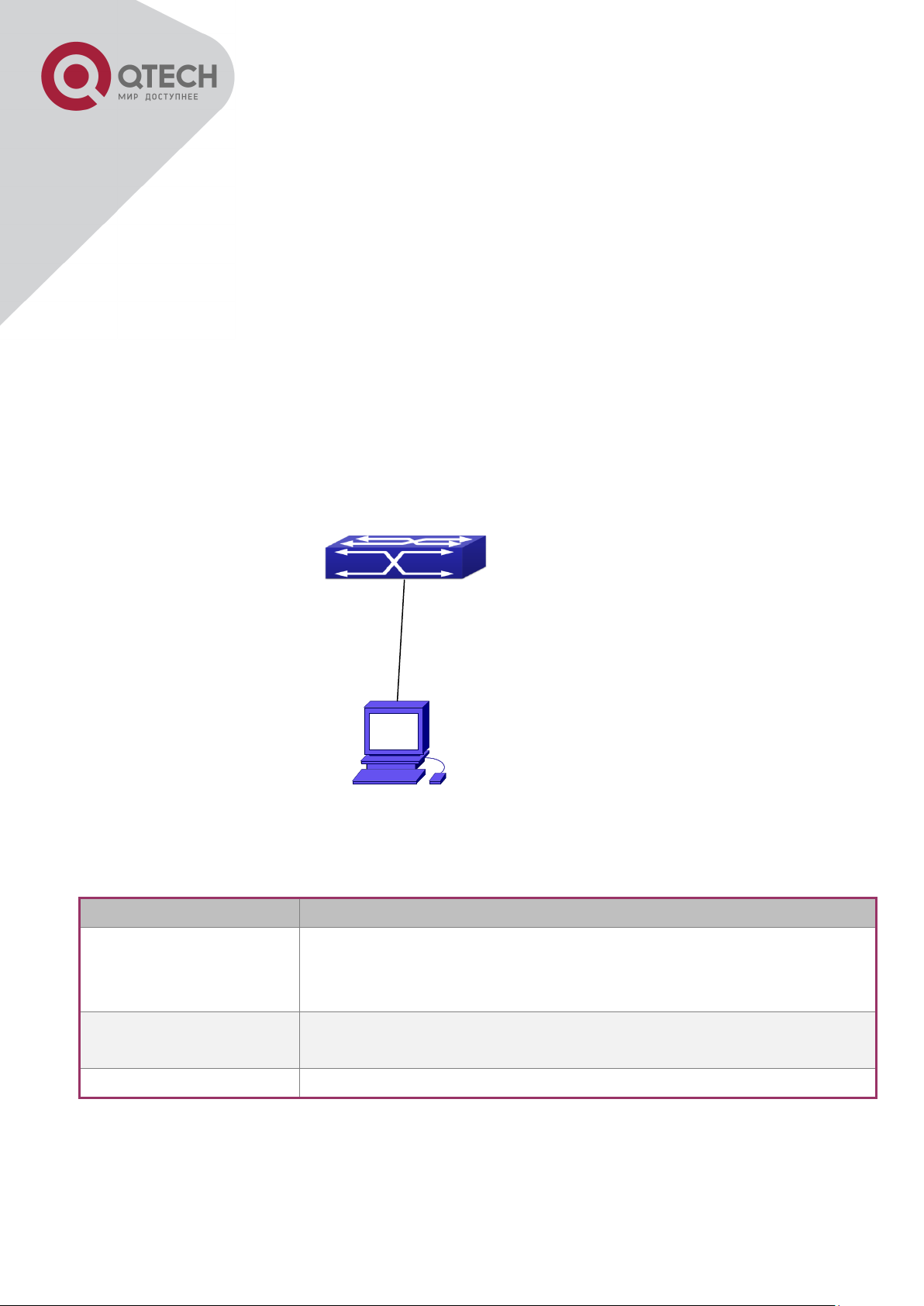
Device Name
Description
PC machine
Has functional keyboard and RS-232, with terminal emulator
installed, such as HyperTerminal included in Windows
9x/NT/2000/XP.
Serial port cable
One end attach to the RS-232 serial port, the other end to the
Console port.
Switch
Functional Console port required.
Connect with serial port
Chapter 1 Switch Management
1.1 Management Options
After purchasing the switch, the user needs to configure the switch for network management.
Switch provides two management options: in-band management and out-of-band management.
1.1.1 Out-Of-Band Management
Out-of-band management is the management through Console interface. Generally, the user
will use out-of-band management for the initial switch configuration, or when in-band
management is not available. For instance, the user must assign an IP address to the switch
via the Console interface to be able to access the switch through Telnet.
The procedures for managing the switch via Console interface are listed below:
Step 1: setting up the environment:
Out-of-band Management Configuration Environment
As shown in above, the serial port (RS-232) is connected to the switch with the serial cable
provided. The table below lists all the devices used in the connection.
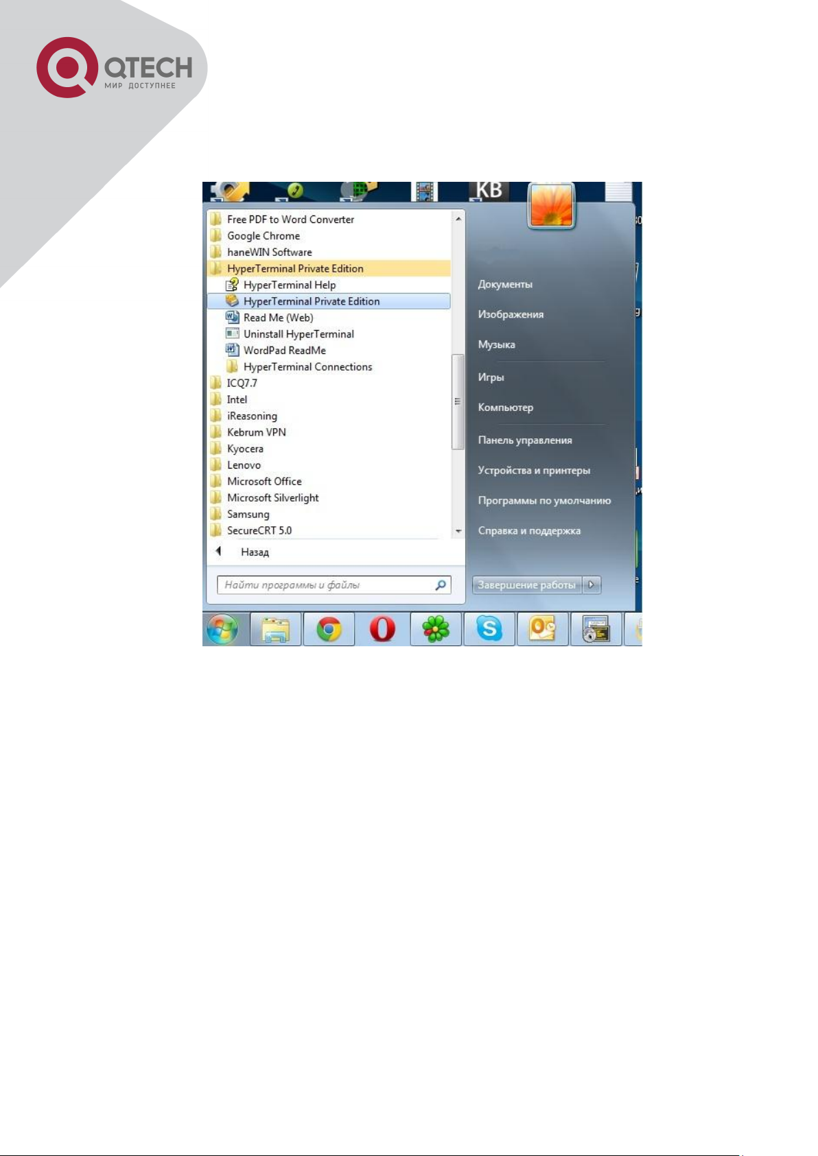
Step 2: Entering the HyperTerminal
+7(495) 797-3311 www.qtech.ru
Москва, Новозаводская ул., 18, стр. 1
Page 18
17
Open the HyperTerminal included in Windows after the connection established. The example
below is based on the HyperTerminal included in Windows XP.
Click Start menu - All Programs -Accessories -Communication - HyperTerminal.
+7(495) 797-3311 www.qtech.ru
Москва, Новозаводская ул., 18, стр. 1
Page 19
18
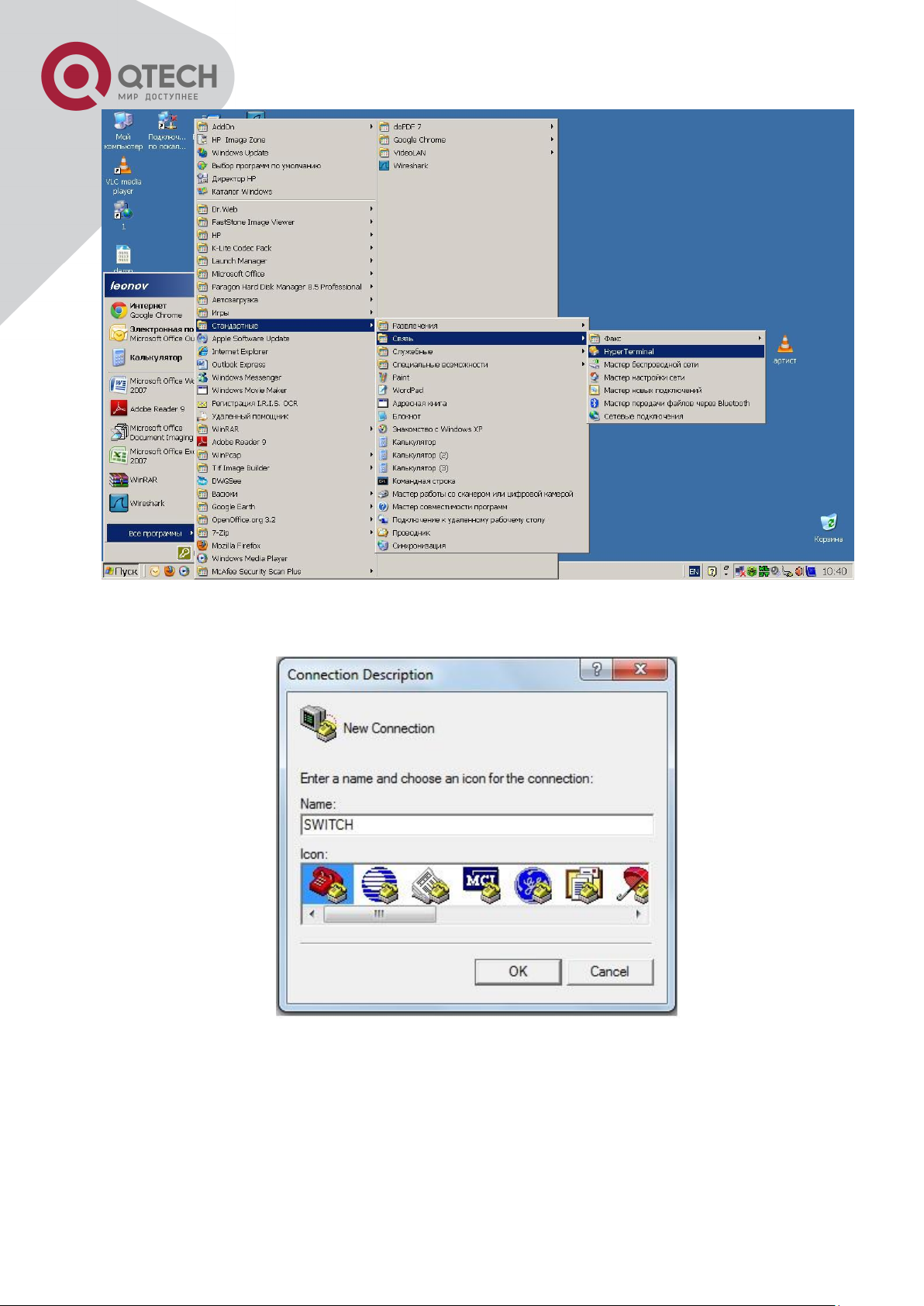
Opening Hyper Terminal
Type a name for opening HyperTerminal, such as “Switch”.
Opening HyperTerminal
In the “Connecting using” drop-list, select the RS-232 serial port used by the PC, e.g. COM1,
and click “OK”.
+7(495) 797-3311 www.qtech.ru
Москва, Новозаводская ул., 18, стр. 1
Page 20
19
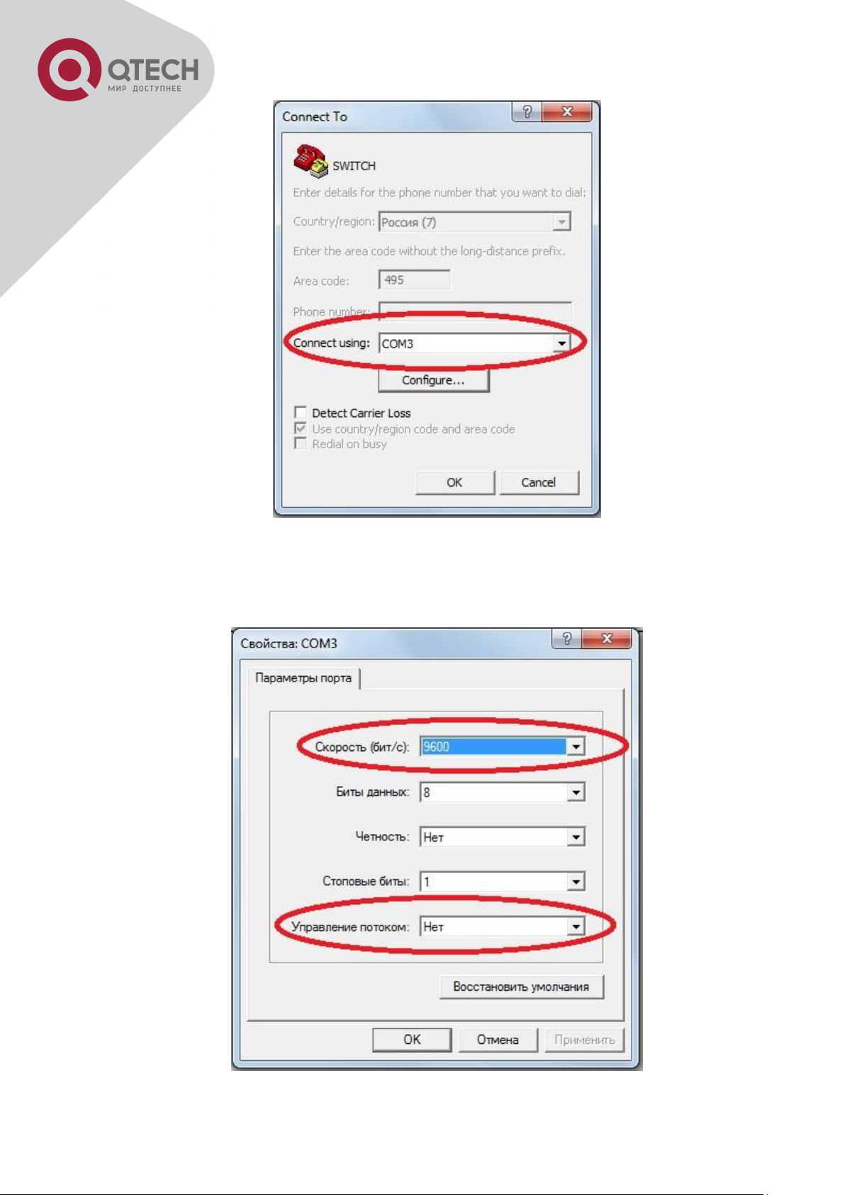
Opening HyperTerminal
COM1 property appears, select “9600” for “Baud rate”, “8” for “Data bits”, “none” for “Parity
checksum”, “1” for stop bit and “none” for traffic control; or, you can also click “Restore default”
and click “OK”.
+7(495) 797-3311 www.qtech.ru
Москва, Новозаводская ул., 18, стр. 1
Page 21

20
Opening HyperTerminal
Step 3: Entering switch CLI interface
Power on the switch, the following appears in the HyperTerminal windows, that is the CLI
configuration mode for Switch.
Testing RAM...
0x077C0000 RAM OK
Loading MiniBootROM...
Attaching to file system ...
Loading nos.img ... done.
Booting......
Starting at 0x10000...
Attaching to file system ...
……
--- Performing Power-On Self Tests (POST) ---
DRAM Test....................PASS!
PCI Device 1 Test............PASS!
FLASH Test...................PASS!
FAN Test.....................PASS!
Done All Pass.
------------------ DONE ---------------------
Current time is SUN JAN 01 00:00:00 2006
……
Switch>
The user can now enter commands to manage the switch. For a detailed description for the
commands, please refer to the following chapters.
1.1.2 In-band Management
In-band management refers to the management by login to the switch using Telnet, or using
HTTP, or using SNMP management software to configure the switch. In-band management
enables management of the switch for some devices attached to the switch. In the case when
in-band management fails due to switch configuration changes, out-of-band management can
be used for configuring and managing the switch.
+7(495) 797-3311 www.qtech.ru
Москва, Новозаводская ул., 18, стр. 1
Page 22
21
Connected with cable
1.1.2.1 Management via Telnet
To manage the switch with Telnet, the following conditions should be met:
1. Switch has an IPv4/IPv6 address configured;
The host IP address (Telnet client) and the switch’s VLAN interface IPv4/IPv6 address is in the
same network segment;
If 2. is not met, Telnet client can connect to an IPv4/IPv6 address of the switch via other
devices, such as a router.
The switch is a Layer 2 switch that can be configured with several IP addresses, the
configuration method refers to the relative chapter. The following example assumes the
shipment status of the switch where only VLAN1 exists in the system.
The following describes the steps for a Telnet client to connect to the switch’s VLAN1 interface
by Telnet(IPV4 address example):
Manage the switch by Telnet
Step 1: Configure the IP addresses for the switch and start the Telnet Server function on the
switch.
First is the configuration of host IP address. This should be within the same network segment
as the switch VLAN1 interface IP address. Suppose the switch VLAN1 interface IP address is
10.1.128.251/24. Then, a possible host IP address is 10.1.128.252/24. Run “ping
10.1.128.251” from the host and verify the result, check for reasons if ping failed.
The IP address configuration commands for VLAN1 interface are listed below. Before in-band
management, the switch must be configured with an IP address by out-of-band management
(i.e. Console mode), the configuration commands are as follows (All switch configuration
prompts are assumed to be “Switch” hereafter if not otherwise specified):
Switch>
Switch>enable
+7(495) 797-3311 www.qtech.ru
Москва, Новозаводская ул., 18, стр. 1
Page 23
22
Switch#config
Switch(config)#interface vlan 1
Switch(Config-if-Vlan1)#ip address 10.1.128.251 255.255.255.0
Switch(Config-if-Vlan1)#no shutdown
To enable the Telnet Server function, users should type the CLI command telnet-server enable
in the global mode as below:
Switch>enable
Switch#config
Switch(config)# telnet-server enable
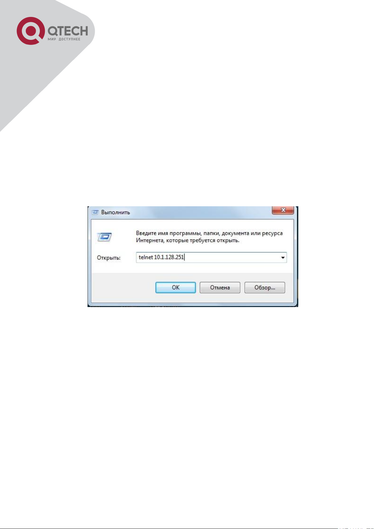
Step 2: Run Telnet Client program.
Run Telnet client program included in Windows with the specified Telnet target.
Run telnet client program included in Windows
Step 3: Login to the switch.
Login to the Telnet configuration interface. Valid login name and password are required,
otherwise the switch will reject Telnet access. This is a method to protect the switch from
unauthorized access. As a result, when Telnet is enabled for configuring and managing the
switch, username and password for authorized Telnet users must be configured with the
following command: username <username> privilege <privilege> [password (0|7) <password>].
To open the local authentication style with the following command: authentication line vty login
local. Privilege option must exist and just is 15. Assume an authorized user in the switch has a
username of “test”, and password of “test”, the configuration procedure should like the
following:
Switch>enable
Switch#config
+7(495) 797-3311 www.qtech.ru
Москва, Новозаводская ул., 18, стр. 1
Page 24

23
Switch(config)#username test privilege 15 password 0 test
Switch(config)#authentication line vty login local
Enter valid login name and password in the Telnet configuration interface, Telnet user will be
able to enter the switch’s CLI configuration interface. The commands used in the Telnet CLI
interface after login is the same as that in the Console interface.
Telnet Configuration Interface
1.1.2.2 Management via HTTP
To manage the switch via HTTP, the following conditions should be met:
1. Switch has an IPv4/IPv6 address configured;
The host IPv4/IPv6 address (HTTP client) and the switch’s VLAN interface IPv4/IPv6 address
are in the same network segment;
If 2. is not met, HTTP client should connect to an IPv4/IPv6 address of the switch via other
devices, such as a router.
Similar to management the switch via Telnet, as soon as the host succeeds to ping/ping6 an
IPv4/IPv6 address of the switch and to type the right login password, it can access the switch
via HTTP. The configuration list is as below:
Step 1: Configure the IP addresses for the switch and start the HTTP server function on the
switch.
For configuring the IP address on the switch through out-of-band management, see the telnet
+7(495) 797-3311 www.qtech.ru
Москва, Новозаводская ул., 18, стр. 1
Page 25
24
management chapter.
To enable the WEB configuration, users should type the CLI command IP http server in the
global mode as below:
Switch>enable
Switch#config
Switch(config)#ip http server
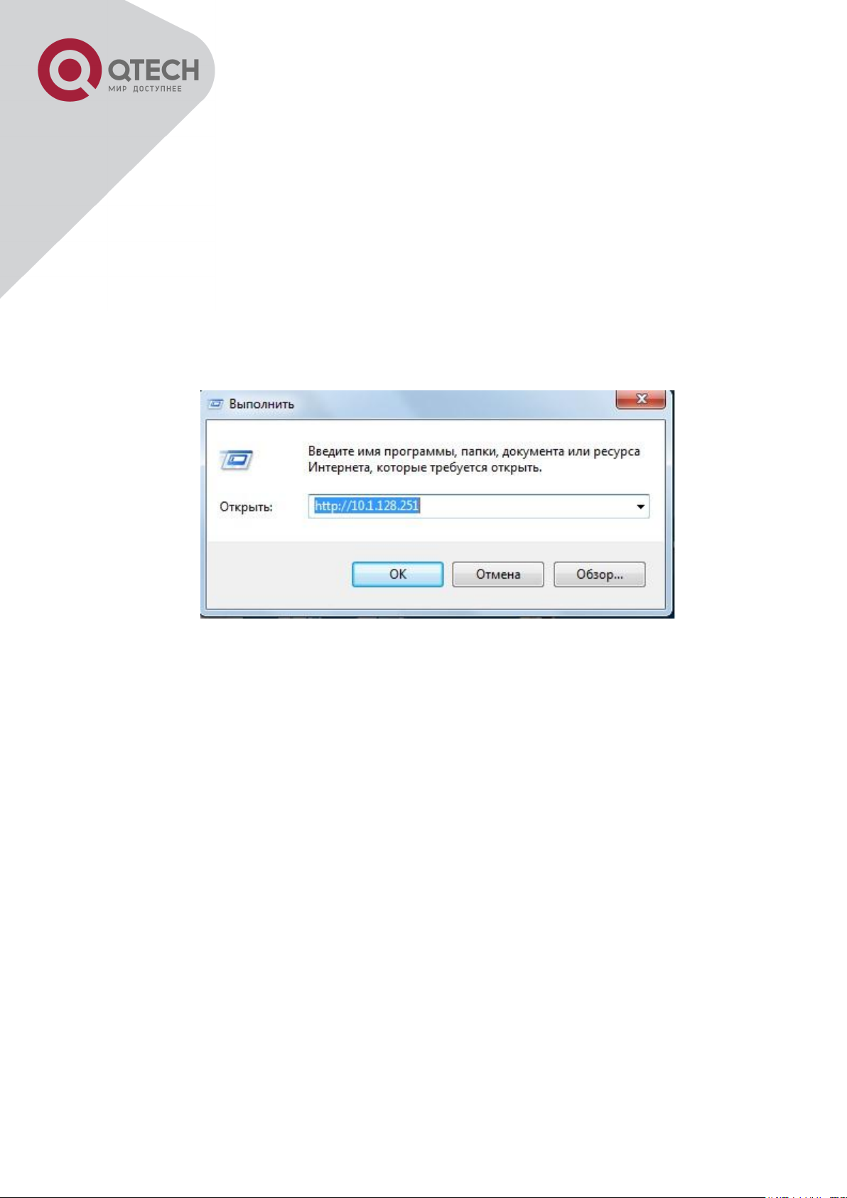
Step 2: Run HTTP protocol on the host.
Open the Web browser on the host and type the IP address of the switch, or run directly the
HTTP protocol on the Windows. For example, the IP address of the switch is “10.1.128.251”;
Run HTTP Protocol
When accessing a switch with IPv6 address, it is recommended to use the Firefox browser
with 1.5 or later version. For example, if the IPv6 address of the switch is 3ffe:506:1:2::3. Input
the IPv6 address of the switch is http://[3ffe:506:1:2::3] and the address should draw together
with the square brackets.
Step 3: Login to the switch.
Login to the Web configuration interface. Valid login name and password are required,
otherwise the switch will reject HTTP access. This is a method to protect the switch from
unauthorized access. As a result, when Telnet is enabled for configuring and managing the
switch, username and password for authorized Telnet users must be configured with the
following command: username <username> privilege <privilege> [password (0|7)
<password>]. To open the local authentication style with the following command:
authentication line web login local. Privilege option must exist and just is 15. Assume an
authorized user in the switch has a username of “admin”, and password of “admin”, the
configuration procedure should like the following:
Switch>enable
+7(495) 797-3311 www.qtech.ru
Москва, Новозаводская ул., 18, стр. 1
Page 26
25
Switch#config
Switch(config)#username admin privilege 15 password 0 admin
Switch(config)#authentication line web login local
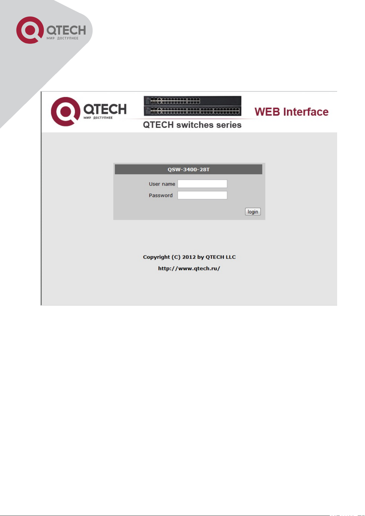
The Web login interface of QSW3400-28T-POE is as below:
Web Login Interface
Input the right username and password, and then the main Web configuration interface is
shown as below.
+7(495) 797-3311 www.qtech.ru
Москва, Новозаводская ул., 18, стр. 1
Page 27

26
Main Web Configuration Interface
Notice: When configure the switch, the name of the switch is composed with English letters.
1.1.2.3 Manage the Switch via SNMP Network Management Software
The necessities required by SNMP network management software to manage switches:
1. IP addresses are configured on the switch;
The IP address of the client host and that of the VLAN interface on the switch it subordinates
to should be in the same segment;
If 2. is not met, the client should be able to reach an IP address of the switch through devices
like routers;
SNMP should be enabled.
The host with SNMP network management software should be able to ping the IP address of
the switch, so that, when running, SNMP network management software will be able to find it
and implement read/write operation on it. Details about how to manage switches via SNMP
network management software will not be covered in this manual, please refer to “Snmp
network management software user manual”.
1.2 CLI Interface
The switch provides thress management interface for users: CLI (Command Line Interface)
interface, Web interface, Snmp netword management software. We will introduce the CLI
interface and Web configuration interface in details, Web interface is familiar with CLI interface
function and will not be covered, please refer to “Snmp network management software user
manual”.
+7(495) 797-3311 www.qtech.ru
Москва, Новозаводская ул., 18, стр. 1
Page 28
27
CLI interface is familiar to most users. As aforementioned, out-of-band management and
Telnet login are all performed through CLI interface to manage the switch.
CLI Interface is supported by Shell program, which consists of a set of configuration
commands. Those commands are categorized according to their functions in switch
configuration and management. Each category represents a different configuration mode. The
Shell for the switch is described below:
Configuration Modes
Configuration Syntax
Shortcut keys
Help function
Input verification
Fuzzy match support
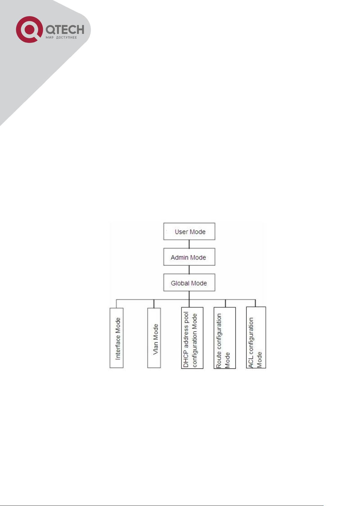
1.2.1 Configuration Modes
Shell Configuration Modes
1.2.1.1 User Mode
On entering the CLI interface, entering user entry system first. If as common user, it is
defaulted to User Mode. The prompt shown is “Switch>“, the symbol “>“ is the prompt for User
Mode. When exit command is run under Admin Mode, it will also return to the User Mode.
Under User Mode, no configuration to the switch is allowed, only clock time and version
+7(495) 797-3311 www.qtech.ru
Москва, Новозаводская ул., 18, стр. 1
Page 29

28
Interface Type
Entry
Operates
Exit
VLAN
Interface
Type interface vlan <Vlanid> command under Global
Mode.
Configure switch IPs,
etc
Use the exit
command to return to
Global Mode.
Ethernet Port
Type interface ethernet
<interface-list> command
under Global Mode.
Configure supported
duplex mode, speed,
etc. of Ethernet Port.
Use the exit
command to return to
Global Mode.
port-channel
Type interface port-channel
<port-channel-number>
command under Global
Mode.
Configure port-channel
related settings such
as duplex mode,
speed, etc.
Use the exit
command to return to
Global Mode.
information of the switch can be queries.
1.2.1.2 Admin Mode
To Admin Mode sees the following: In user entry system, if as Admin user, it is defaulted to
Admin Mode. Admin Mode prompt “Switch#” can be entered under the User Mode by running
the enable command and entering corresponding access levels admin user password, if a
password has been set. Or, when exit command is run under Global Mode, it will also return to
the Admin Mode. Switch also provides a shortcut key sequence "Ctrl+z”, this allows an easy
way to exit to Admin Mode from any configuration mode (except User Mode).
Under Admin Mode, the user can query the switch configuration information, connection status
and traffic statistics of all ports; and the user can further enter the Global Mode from Admin
Mode to modify all configurations of the switch. For this reason, a password must be set for
entering Admin mode to prevent unauthorized access and malicious modification to the switch.
1.2.1.3 Global Mode
Type the config command under Admin Mode will enter the Global Mode prompt
“Switch(config)#”. Use the exit command under other configuration modes such as Port Mode,
VLAN mode will return to Global Mode.
The user can perform global configuration settings under Global Mode, such as MAC Table,
Port Mirroring, VLAN creation, IGMP Snooping start and STP, etc. And the user can go further
to Port Mode for configuration of all the interfaces.
1.2.1.4 Interface Mode
Use the interface command under Global Mode can enter the interface mode specified. Switch
provides three interface type: 1. VLAN interface; 2. Ethernet port; 3. port-channel, accordingly
the three interface configuration modes.
+7(495) 797-3311 www.qtech.ru
Москва, Новозаводская ул., 18, стр. 1
Page 30

29
ACL type
Entry
Operates
Exit
Standard IP
ACL Mode
Type ip access-list
standard command under
Global Mode.
Configure parameters for
Standard IP ACL Mode.
Use the exit
command to return
to Global Mode.
Extended IP
ACL Mode
Type ip access-list
extanded command under
Global Mode.
Configure parameters for
Extended IP ACL Mode.
Use the exit
command to return
to Global Mode.
1.2.1.5 VLAN Mode
Using the vlan <vlan-id> command under Global Mode can enter the corresponding VLAN
Mode. Under VLAN Mode the user can configure all member ports of the corresponding VLAN.
Run the exit command to exit the VLAN Mode to Global Mode.
1.2.1.6 DHCP Address Pool Mode
Type the ip dhcp pool <name> command under Global Mode will enter the DHCP Address
Pool Mode prompt “Switch(Config-<name>-dhcp)#”. DHCP address pool properties can be
configured under DHCP Address Pool Mode. Run the exit command to exit the DHCP Address
Pool Mode to Global Mode.
1.2.1.7 ACL Mode
1.2.2 Configuration Syntax
Switch provides various configuration commands. Although all the commands are different,
they all abide by the syntax for Switch configuration commands. The general commands
format of Switch is shown below:
cmdtxt <variable> {enum1 | … | enumN } [option1 | … | optionN]
Conventions: cmdtxt in bold font indicates a command keyword; <variable> indicates a
variable parameter; {enum1 | … | enumN } indicates a mandatory parameter that should be
selected from the parameter set enum1~enumN; and the square bracket ([ ]) in [option1 | … |
optionN] indicate an optional parameter. There may be combinations of “< >“, “{ }” and “[ ]” in
the command line, such as [<variable>], {enum1 <variable>| enum2}, [option1 [option2]],
etc.
Here are examples for some actual configuration commands:
show version, no parameters required. This is a command with only a keyword and no
parameter, just type in the command to run.
vlan <vlan-id>, parameter values are required after the keyword.
+7(495) 797-3311 www.qtech.ru
Москва, Новозаводская ул., 18, стр. 1
Page 31

30
Key(s)
Function
Back
Space
Delete a character before the cursor, and the cursor moves back.
Up “↑”
Show previous command entered. Up to ten recently entered commands can be
shown.
Down
“↓”
Show next command entered. When use the Up key to get previously entered
commands, you can use the Down key to return to the next command
Left “←”
The cursor moves one character
to the left.
You can use the Left and Right key to modify an
entered command.
Right
“→”
The cursor moves one character
to the right.
Ctrl +p
The same as Up key “↑”.
Ctrl +n
The same as Down key “↓”.
Ctrl +b
The same as Left key “←”.
Ctrl +f
The same as Right key “→”.
Ctrl +z
Return to the Admin Mode directly from the other configuration modes (except
User Mode).
Ctrl +c
Break the ongoing command process, such as ping or other command execution.
Tab
When a string for a command or keyword is entered, the Tab can be used to
complete the command or keyword if there is no conflict.
Access to Help
Usage and function
firewall {enable | disable}, user can enter firewall enable or firewall disable for this
command.
snmp-server community {ro | rw} <string>, the followings are possible:
snmp-server community ro <string>
snmp-server community rw <string>
1.2.3 Shortcut Key Support
Switch provides several shortcut keys to facilitate user configuration, such as up, down, left,
right and Blank Space. If the terminal does not recognize Up and Down keys, ctrl +p and ctrl
+n can be used instead.
1.2.4 Help Function
There are two ways in Switch for the user to access help information: the “help” command and
the “?”.
+7(495) 797-3311 www.qtech.ru
Москва, Новозаводская ул., 18, стр. 1
Page 32

31
Help
Under any command line prompt, type in “help” and press Enter will get a
brief description of the associated help system.
“?”
Under any command line prompt, enter “?” to get a command list of the
current mode and related brief description.
Enter a “?” after the command keyword with an embedded space. If the
position should be a parameter, a description of that parameter type,
scope, etc, will be returned; if the position should be a keyword, then a set
of keywords with brief description will be returned; if the output is “<cr>“,
then the command is complete, press Enter to run the command.
A “?” immediately following a string. This will display all the commands that
begin with that string.
Output error message
Explanation
Unrecognized command or illegal
parameter!
The entered command does not exist, or there is
error in parameter scope, type or format.
Ambiguous command
At least two interpretations is possible basing on the
current input.
Invalid command or parameter
The command is recognized, but no valid parameter
record is found.
This command is not exist in
current mode
The command is recognized, but this command can
not be used under current mode.
Please configure precursor
command "*" at first!
The command is recognized, but the prerequisite
command has not been configured.
syntax error: missing '"' before the
end of command line!
Quotation marks are not used in pairs.
1.2.5 Input Verification
1.2.5.1 Returned Information: success
All commands entered through keyboards undergo syntax check by the Shell. Nothing will be
returned if the user entered a correct command under corresponding modes and the execution
is successful.
Returned Information: error
1.2.6 Fuzzy Match Support
Switch shell support fuzzy match in searching command and keyword. Shell will recognize
commands or keywords correctly if the entered string causes no conflict.
For example:
+7(495) 797-3311 www.qtech.ru
Москва, Новозаводская ул., 18, стр. 1
Page 33

32
1. For command “show interfaces status ethernet1/1”, typing “sh in status ethernet1/1” will
work.
However, for command “show running-config”, the system will report a “> Ambiguous
command!” error if only “show r” is entered, as Shell is unable to tell whether it is “show run” or
“show running-config”. Therefore, Shell will only recognize the command if “sh ru” is entered.
+7(495) 797-3311 www.qtech.ru
Москва, Новозаводская ул., 18, стр. 1
Page 34

33
Command
Explanation
Normal User Mode/ Admin Mode
enable [<1-15>]
disable
The User uses enable command to step into admin mode from
normal user mode or modify the privilege level of the users.
The disable command is for exiting admin mode.
Admin Mode
config [terminal]
Enter global mode from admin mode.
Various Modes
exit
Exit current mode and enter previous mode, such as using this
command in global mode to go back to admin mode, and back
to normal user mode from admin mode.
show privilege
Show privilege of the current users.
Except User Mode/ Admin Mode
end
Quit current mode and return to Admin mode when not at User
Mode/ Admin Mode.
Admin Mode
clock set <HH:MM:SS>
[YYYY.MM.DD]
Set system date and time.
show version
Display version information of the switch.
set default
Restore to the factory default.
write
Save current configuration parameters to Flash Memory.
reload
Hot reset the switch.
show cpu usage
Show CPU usage rate.
show cpu utilization
Show current CPU utilization rate.
show memory usage
Show memory usage rate.
Global Mode
Chapter 2 Basic Switch Configuration
2.1 Basic Configuration
Basic switch configuration includes commands for entering and exiting the admin mode,
commands for entering and exiting interface mode, for configuring and displaying the switch
clock, for displaying the version information of the switch system, etc.
+7(495) 797-3311 www.qtech.ru
Москва, Новозаводская ул., 18, стр. 1
Page 35

34
banner motd <LINE>
no banner motd
Configure the information displayed when the login
authentication of a telnet or console user is successful.
Command
Explanation
Global Mode
telnet-server enable
no telnet-server enable
Enable the Telnet server function in the
switch: the no command disables the Telnet
function.
username <user-name> [privilege
<privilege>] [password [0 | 7] <password>]
no username <username>
Configure user name and password of the
telnet. The no form command deletes the
telnet user authorization.
aaa authorization config-commands
Enable command authorization function for
2.2 Telnet Management
2.2.1 Telnet
2.2.1.1 Introduction to Telnet
Telnet is a simple remote terminal protocol for remote login. Using Telnet, the user can login to
a remote host with its IP address of hostname from his own workstation. Telnet can send the
user’s keystrokes to the remote host and send the remote host output to the user’s screen
through TCP connection. This is a transparent service, as to the user, the keyboard and
monitor seems to be connected to the remote host directly.
Telnet employs the Client-Server mode, the local system is the Telnet client and the remote
host is the Telnet server. Switch can be either the Telnet Server or the Telnet client.
When switch is used as the Telnet server, the user can use the Telnet client program included
in Windows or the other operation systems to login to switch, as described earlier in the Inband management section. As a Telnet server, switch allows up to 5 telnet client TCP
connections.
And as Telnet client, using telnet command under Admin Mode allows the user to login to the
other remote hosts. Switch can only establish TCP connection to one remote host. If a
connection to another remote host is desired, the current TCP connection must be dropped.
2.2.1.2 Telnet Configuration Task List
1. Configure Telnet Server
Telnet to a remote host from the switch.
1. Configure Telnet Server
+7(495) 797-3311 www.qtech.ru
Москва, Новозаводская ул., 18, стр. 1
Page 36

35
no aaa authorization config-commands
the login user with VTY (login with Telnet and
SSH). The no command disables this
function. Only enabling this command and
configuring command authorization manner,
it will request to authorize when executing
some command.
authentication securityip <ip-addr>
no authentication securityip <ip-addr>
Configure the secure IP address to login to
the switch through Telnet: the no command
deletes the authorized Telnet secure address.
authentication securityipv6 <ipv6-addr>
no authentication securityipv6 <ipv6-addr>
Configure IPv6 security address to login to
the switch through Telnet; the no command
deletes the authorized Telnet security
address.
authentication ip access-class {<numstd>|<name>}
no authentication ip access-class
Binding standard IP ACL protocol to login with
Telnet/SSH/Web; the no form command will
cancel the binding ACL.
authentication ipv6 access-class {<numstd>|<name>}
no authentication ipv6 access-class
Binding standard IPv6 ACL protocol to login
with Telnet/SSH/Web; the no form command
will cancel the binding ACL.
authentication line {console | vty | web}
login method1 [method2 …]
no authentication line {console | vty | web}
login
Configure authentication method list with
telnet.
authentication enable method1
[method2 …]
no authentication enable
Configure the enable authentication method
list.
authorization line {console | vty | web} exec
method1 [method2 …]
no authorization line {console | vty | web}
exec
Configure the authorization method list with
telnet.
authorization line vty command <1-15>
{local | radius | tacacs} (none|)
no authorization line vty command <1-15>
Configure command authorization manner
and authorization selection priority of login
user with VTY (login with Telnet and SSH).
The no command recovers to be default
manner.
accounting line {console | vty} command
<1-15> {start-stop | stop-only | none}
Configure the accounting method list.
+7(495) 797-3311 www.qtech.ru
Москва, Новозаводская ул., 18, стр. 1
Page 37

36
method1 [method2…]
no accounting line {console | vty}
command <1-15>
Admin Mode
terminal monitor
terminal no monitor
Display debug information for Telnet client
login to the switch; the no command disables
the debug information.
Telnet to a remote host from the switch
Command
Explanation
Admin Mode
telnet [vrf <vrf-name>] {<ip-addr> | <ipv6addr> | host <hostname>} [<port>]
Login to a remote host with the Telnet client
included in the switch.
Command
Explanation
Global Mode
ssh-server enable
no ssh-server enable
Enable SSH function on the switch; the no
command disables SSH function.
username <username> [privilege
<privilege>] [password [0 | 7] <password>]
no username <username>
Configure the username and password of
SSH client software for logging on the switch;
the no command deletes the username.
ssh-server timeout <timeout>
no ssh-server timeout
Configure timeout value for SSH
authentication; the no command restores the
default timeout value for SSH authentication.
2.2.2 SSH
2.2.2.1 Introduction to SSH
SSH (Secure Shell) is a protocol which ensures a secure remote access connection to network
devices. It is based on the reliable TCP/IP protocol. By conducting the mechanism such as key
distribution, authentication and encryption between SSH server and SSH client, a secure
connection is established. The information transferred on this connection is protected from
being intercepted and decrypted. The switch meets the requirements of SSH2.0. It supports
SSH2.0 client software such as SSH Secure Client and putty. Users can run the above
software to manage the switch remotely.
The switch presently supports RSA authentication, 3DES cryptography protocol and SSH user
password authentication etc.
2.2.2.2 SSH Server Configuration Task List
+7(495) 797-3311 www.qtech.ru
Москва, Новозаводская ул., 18, стр. 1
Page 38

37
ssh-server authentication-retires
<authentication-retires>
no ssh-server authentication-retries
Configure the number of times for retrying
SSH authentication; the no command
restores the default number of times for
retrying SSH authentication.
ssh-server host-key create rsa modulus
<moduls>
Generate the new RSA host key on the SSH
server.
Admin Mode
terminal monitor
terminal no monitor
Display SSH debug information on the SSH
client side; the no command stops displaying
SSH debug information on the SSH client
side.
show crypto key
Show the secret key of ssh.
rypto key clear rsa
Clear the secret key of ssh.
2.2.2.3 Example of SSH Server Configuration
Example1:
Requirement: Enable SSH server on the switch, and run SSH2.0 client software such as
Secure shell client or putty on the terminal. Log on the switch by using the username and
password from the client.
Configure the IP address, add SSH user and enable SSH service on the switch. SSH2.0 client
can log on the switch by using the username and password to configure the switch.
Switch(config)#ssh-server enable
Switch(config)#interface vlan 1
Switch(Config-if-Vlan1)#ip address 100.100.100.200 255.255.255.0
Switch(Config-if-Vlan1)#exit
Switch(config)#username test privilege 15 password 0 test
In IPv6 networks, the terminal should run SSH client software which support IPv6, such as
putty6. Users should not modify the configuration of the switch except allocating an IPv6
address for the local host.
2.3 Configure Switch IP Addresses
All Ethernet ports of switch are default to Data Link layer ports and perform layer 2 forwarding.
VLAN interface represent a Layer 3 interface function which can be assigned an IP address,
which is also the IP address of the switch. All VLAN interface related configuration commands
can be configured under VLAN Mode. Switch provides three IP address configuration methods:
Manual
+7(495) 797-3311 www.qtech.ru
Москва, Новозаводская ул., 18, стр. 1
Page 39

38
Command
Explanation
Global Mode
interface vlan <vlan-id>
no interface vlan <vlan-id>
Create VLAN interface (layer 3 interface); the
no command deletes the VLAN interface.
Command
Explanation
VLAN Interface Mode
ip address <ip_address> <mask>
[secondary]
no ip address <ip_address> <mask>
[secondary]
Configure IP address of VLAN interface; the
no command deletes IP address of VLAN
interface.
ipv6 address <ipv6-address / prefixlength> [eui-64]
no ipv6 address <ipv6-address / prefixlength>
Configure IPv6 address, including aggregation
global unicast address, local site address and
local link address. The no command deletes
IPv6 address.
Command
Explanation
VLAN Interface Mode
ip bootp-client enable
Enable the switch to be a BootP client and
BOOTP
DHCP
Manual configuration of IP address is assign an IP address manually for the switch.
In BOOTP/DHCP mode, the switch operates as a BOOTP/DHCP client, send broadcast
packets of BOOTPRequest to the BOOTP/DHCP servers, and the BOOTP/DHCP servers
assign the address on receiving the request. In addition, switch can act as a DHCP server, and
dynamically assign network parameters such as IP addresses, gateway addresses and DNS
server addresses to DHCP clients DHCP Server configuration is detailed in later chapters.
2.3.1 Switch IP Addresses Configuration Task List
1. Enable VLAN port mode
Manual configuration
BOOTP configuration
DHCP configuration
1. Enable VLAN port mode
Manual configuration
BOOTP configuration
+7(495) 797-3311 www.qtech.ru
Москва, Новозаводская ул., 18, стр. 1
Page 40

39
no ip bootp-client enable
obtain IP address and gateway address
through BootP negotiation; the no command
disables the BootP client function.
DHCP configuration
Command
Explanation
VLAN Interface Mode
ip bootp-client enable
no ip bootp-client enable
Enable the switch to be a DHCP client and
obtain IP address and gateway address
through DHCP negotiation; the no command
disables the DHCP client function.
2.4 SNMP Configuration
2.4.1 Introduction to SNMP
SNMP (Simple Network Management Protocol) is a standard network management protocol
widely used in computer network management. SNMP is an evolving protocol. SNMP v1
[RFC1157] is the first version of SNMP which is adapted by vast numbers of manufacturers for
its simplicity and easy implementation; SNMP v2c is an enhanced version of SNMP v1, which
supports layered network management; SNMP v3 strengthens the security by adding USM
(User-based Security Mode) and VACM (View-based Access Control Model).
SNMP protocol provides a simple way of exchange network management information between
two points in the network. SNMP employs a polling mechanism of message query, and
transmits messages through UDP (a connectionless transport layer protocol). Therefore it is
well supported by the existing computer networks.
SNMP protocol employs a station-agent mode. There are two parts in this structure: NMS
(Network Management Station) and Agent. NMS is the workstation on which SNMP client
program is running. It is the core on the SNMP network management. Agent is the server
software runs on the devices which need to be managed. NMS manages all the managed
objects through Agents. The switch supports Agent function.
The communication between NMS and Agent functions in Client/Server mode by exchanging
standard messages. NMS sends request and the Agent responds. There are seven types of
SNMP message:
Get-Request
Get-Response
Get-Next-Request
Get-Bulk-Request
+7(495) 797-3311 www.qtech.ru
Москва, Новозаводская ул., 18, стр. 1
Page 41

40
Set-Request
Trap
Inform-Request
NMS sends queries to the Agent with Get-Request, Get-Next-Request, Get-Bulk-Request and
Set-Request messages; and the Agent, upon receiving the requests, replies with GetResponse message. On some special situations, like network device ports are on Up/Down
status or the network topology changes, Agents can send Trap messages to NMS to inform the
abnormal events. Besides, NMS can also be set to alert to some abnormal events by enabling
RMON function. When alert events are triggered, Agents will send Trap messages or log the
event according to the settings. Inform-Request is mainly used for inter-NMS communication in
the layered network management.
USM ensures the transfer security by well-designed encryption and authentication. USM
encrypts the messages according to the user typed password. This mechanism ensures that
the messages can’t be viewed on transmission. And USM authentication ensures that the
messages can’t be changed on transmission. USM employs DES-CBC cryptography. And
HMAC-MD5 and HMAC-SHA are used for authentication.
VACM is used to classify the users’ access permission. It puts the users with the same access
permission in the same group. Users can’t conduct the operation which is not authorized.
2.4.2 Introduction to MIB
The network management information accessed by NMS is well defined and organized in a
Management Information Base (MIB). MIB is pre-defined information which can be accessed
by network management protocols. It is in layered and structured form. The pre-defined
management information can be obtained from monitored network devices. ISO ASN.1 defines
a tree structure for MID. Each MIB organizes all the available information with this tree
structure. And each node on this tree contains an OID (Object Identifier) and a brief description
about the node. OID is a set of integers divided by periods. It identifies the node and can be
used to locate the node in a MID tree structure, shown in the figure below:
+7(495) 797-3311 www.qtech.ru
Москва, Новозаводская ул., 18, стр. 1
Page 42

41
ASN.1 Tree Instance
In this figure, the OID of the object A is 1.2.1.1. NMS can locate this object through this unique
OID and gets the standard variables of the object. MIB defines a set of standard variables for
monitored network devices by following this structure.
If the variable information of Agent MIB needs to be browsed, the MIB browse software needs
to be run on the NMS. MIB in the Agent usually consists of public MIB and private MIB. The
public MIB contains public network management information that can be accessed by all NMS;
private MIB contains specific information which can be viewed and controlled by the support of
the manufacturers.
MIB-I [RFC1156] is the first implemented public MIB of SNMP, and is replaced by MIB-II
[RFC1213]. MIB-II expands MIB-I and keeps the OID of MIB tree in MIB-I. MIB-II contains subtrees which are called groups. Objects in those groups cover all the functional domains in
network management. NMS obtains the network management information by visiting the MIB
of SNMP Agent.
The switch can operate as a SNMP Agent, and supports both SNMP v1/v2c and SNMP v3.
The switch supports basic MIB-II, RMON public MIB and other public MID such as BRIDGE
MIB. Besides, the switch supports self-defined private MIB.
2.4.3 Introduction to RMON
RMON is the most important expansion of the standard SNMP. RMON is a set of MIB
definitions, used to define standard network monitor functions and interfaces, enabling the
communication between SNMP management terminals and remote monitors. RMON provides
a highly efficient method to monitor actions inside the subnets.
MID of RMON consists of 10 groups. The switch supports the most frequently used group 1, 2,
3 and 9:
Statistics: Maintain basic usage and error statistics for each subnet monitored by the Agent.
+7(495) 797-3311 www.qtech.ru
Москва, Новозаводская ул., 18, стр. 1
Page 43

42
Command
Explanation
Global Mode
snmp-server enabled
no snmp-server enabled
Enable the SNMP Agent function on the
switch; the no command disables the SNMP
Agent function on the switch.
Command
Explanation
Global Mode
snmp-server community {ro | rw} {0 | 7}
Configure the community string for the switch;
History: Record periodical statistic samples available from Statistics.
Alarm: Allow management console users to set any count or integer for sample intervals and
alert thresholds for RMON Agent records.
Event: A list of all events generated by RMON Agent.
Alarm depends on the implementation of Event. Statistics and History display some current or
history subnet statistics. Alarm and Event provide a method to monitor any integer data
change in the network, and provide some alerts upon abnormal events (sending Trap or record
in logs).
2.4.4 SNMP Configuration
2.4.4.1 SNMP Configuration Task List
1. Enable or disable SNMP Agent server function
2. Configure SNMP community string
3. Configure IP address of SNMP management base
4. Configure engine ID
5. Configure user
6. Configure group
7. Configure view
8. Configuring TRAP
9. Enable/Disable RMON
1. Enable or disable SNMP Agent server function
2. Configure SNMP community string
+7(495) 797-3311 www.qtech.ru
Москва, Новозаводская ул., 18, стр. 1
Page 44

43
<string> [access {<num-std>|<name>}]
[ipv6-access {<ipv6-num-std>|<ipv6name>}] [read <read-view-name>] [write
<write-view-name>]
no snmp-server community <string>
[access {<num-std>|<name>}] [ipv6-access
{<ipv6-num-std>|<ipv6-name>}]
the no command deletes the configured
community string.
Command
Explanation
Global Mode
snmp-server securityip { <ipv4-address> |
<ipv6-address> }
no snmp-server securityip { <ipv4address> | <ipv6-address> }
Configure IPv4/IPv6 security address which is
allowed to access the switch on the NMS; the
no command deletes the configured security
address.
snmp-server securityip enable
snmp-server securityip disable
Enable or disable secure IP address check
function on the NMS.
Command
Explanation
Global Mode
snmp-server engineid <engine-string>
no snmp-server engineid
Configure the local engine ID on the switch.
This command is used for SNMP v3.
Command
Explanation
Global Mode
snmp-server user <use-string> <groupstring> [{authPriv | authNoPriv} auth {md5
| sha} <word>] [access {<numstd>|<name>}] [ipv6-access {<ipv6-numstd>|<ipv6-name>}]
no snmp-server user <user-string> [access
{<num-std>|<name>}] [ipv6-access {<ipv6num-std>|<ipv6-name>}]
Add a user to a SNMP group. This command
is used to configure USM for SNMP v3.
3. Configure IP address of SNMP management station
4. Configure engine ID
5. Configure user
+7(495) 797-3311 www.qtech.ru
Москва, Новозаводская ул., 18, стр. 1
Page 45

44
6. Configure group
Command
Explanation
Global Mode
snmp-server group <group-string>
{noauthnopriv|authnopriv|authpriv} [[read
<read-string>] [write <write-string>] [notify
<notify-string>]] [access {<numstd>|<name>}] [ipv6-access {<ipv6-numstd>|<ipv6-name>}]
no snmp-server group <group-string>
{noauthnopriv|authnopriv|authpriv}
[access {<num-std>|<name>}] [ipv6-access
{<ipv6-num-std>|<ipv6-name>}]
Set the group information on the switch. This
command is used to configure VACM for
SNMP v3.
Command
Explanation
Global Mode
snmp-server view <view-string> <oidstring> {include|exclude}
no snmp-server view <view-string> [<oidstring>]
Configure view on the switch. This command
is used for SNMP v3.
Command
Explanation
Global Mode
snmp-server enable traps
no snmp-server enable traps
Enable the switch to send Trap message. This
command is used for SNMP v1/v2/v3.
snmp-server host { <host-ipv4-address> |
<host-ipv6-address> } {v1 | v2c | {v3
{noauthnopriv | authnopriv | authpriv}}}
<user-string>
no snmp-server host { <host-ipv4address> | <host-ipv6-address> } {v1 | v2c |
{v3 {noauthnopriv | authnopriv | authpriv}}}
<user-string>
Set the host IPv4/IPv6 address which is used
to receive SNMP Trap information. For SNMP
v1/v2, this command also configures Trap
community string; for SNMP v3, this
command also configures Trap user name
and security level. The “no” form of this
command cancels this IPv4 or IPv6 address.
snmp-server trap-source {<ipv4-address> |
Set the source IPv4 or IPv6 address which is
7. Configure view
8. Configuring TRAP
+7(495) 797-3311 www.qtech.ru
Москва, Новозаводская ул., 18, стр. 1
Page 46

45
<ipv6-address>}
no snmp-server trap-source {<ipv4address> | <ipv6-address>}
used to send trap packet, the no command
deletes the configuration.
Command
Explanation
Global mode
rmon enable
no rmon enable
Enable/disable RMON.
9. Enable/Disable RMON
2.4.5 Typical SNMP Configuration Examples
The IP address of the NMS is 1.1.1.5; the IP address of the switch (Agent) is 1.1.1.9.
Scenario 1: The NMS network administrative software uses SNMP protocol to obtain data
from the switch.
The configuration on the switch is listed below:
Switch(config)#snmp-server enable
Switch(config)#snmp-server community rw private
Switch(config)#snmp-server community ro public
Switch(config)#snmp-server securityip 1.1.1.5
The NMS can use private as the community string to access the switch with read-write
permission, or use public as the community string to access the switch with read-only
permission.
Scenario 2: NMS will receive Trap messages from the switch (Note: NMS may have
community string verification for the Trap messages. In this scenario, the NMS uses a Trap
verification community string of usertrap).
The configuration on the switch is listed below:
Switch(config)#snmp-server enable
Switch(config)#snmp-server host 1.1.1.5 v1 usertrap
Switch(config)#snmp-server enable traps
Scenario 3: NMS uses SNMP v3 to obtain information from the switch.
The configuration on the switch is listed below:
Switch(config)#snmp-server
Switch(config)#snmp-server user tester UserGroup authPriv auth md5
+7(495) 797-3311 www.qtech.ru
Москва, Новозаводская ул., 18, стр. 1
Page 47

46
hellotst
Switch(config)#snmp-server group UserGroup AuthPriv read max write
max notify max
Switch(config)#snmp-server view max 1 include
Scenario 4: NMS wants to receive the v3Trap messages sent by the switch.
The configuration on the switch is listed below:
Switch(config)#snmp-server enable
Switch(config)#snmp-server host 10.1.1.2 v3 authpriv tester
Switch(config)#snmp-server enable traps
Scenario 5: The IPv6 address of the NMS is 2004:1:2:3::2; the IPv6 address of the switch
(Agent) is 2004:1:2:3::1. The NMS network administrative software uses SNMP protocol to
obtain data from the switch.
The configuration on the switch is listed below:
Switch(config)#snmp-server enable
Switch(config)#snmp-server community rw private
Switch(config)#snmp-server community ro public
Switch(config)#snmp-server securityip 2004:1:2:3::2
The NMS can use private as the community string to access the switch with read-write
permission, or use public as the community string to access the switch with read-only
permission.
Scenario 6: NMS will receive Trap messages from the switch (Note: NMS may have
community string verification for the Trap messages. In this scenario, the NMS uses a Trap
verification community string of usertrap).
The configuration on the switch is listed below:
Switch(config)#snmp-server host 2004:1:2:3::2 v1 usertrap
Switch(config)#snmp-server enable traps
2.4.6 SNMP Troubleshooting
When users configure the SNMP, the SNMP server may fail to run properly due to physical
connection failure and wrong configuration, etc. Users can troubleshoot the problems by
following the guide below:
Good condition of the physical connection.
+7(495) 797-3311 www.qtech.ru
Москва, Новозаводская ул., 18, стр. 1
Page 48

47
Interface and datalink layer protocol is Up (use the “show interface” command), and the
connection between the switch and host can be verified by ping (use “ping” command).
The switch enabled SNMP Agent server function (use “snmp-server” command)
Secure IP for NMS (use “snmp-server securityip” command) and community string (use
“snmp-server community” command) are correctly configured, as any of them fails,
SNMP will not be able to communicate with NMS properly.
If Trap function is required, remember to enable Trap (use “snmp-server enable traps”
command). And remember to properly configure the target host IP address and
community string for Trap (use “snmp-server host” command) to ensure Trap message
can be sent to the specified host.
If RMON function is required, RMON must be enabled first (use “rmon enable”
command).
Use “show snmp” command to verify sent and received SNMP messages; Use “show
snmp status” command to verify SNMP configuration information; Use “debug snmp
packet” to enable SNMP debugging function and verify debug information.
If users still can’t solve the SNMP problems, Please contact our technical and service center.
2.5 Switch Upgrade
Switch provides two ways for switch upgrade: BootROM upgrade and the TFTP/FTP upgrade
under Shell.
2.5.1 Switch System Files
The system files includes system image file and boot file. The updating of the switch is to
update the two files by overwrite the old files with the new ones.
The system image files refers to the compressed files of the switch hardware drivers, and
software support program, etc, namely what we usually call the IMG update file. The IMG file
can only be saved in the FLASH with a defined name of nos.img
The boot file is for initiating the switch, namely what we usually call the ROM update file (It can
be compressed into IMG file if it is of large size). In switch, the boot file is allowed to save in
ROM only. Switch mandates the name of the boot file to be boot.rom.
The update method of the system image file and the boot file is the same. The switch supplies
the user with two modes of updating: 1. BootROM mode; 2. TFTP and FTP update at Shell
mode. This two update method will be explained in details in following two sections.
+7(495) 797-3311 www.qtech.ru
Москва, Новозаводская ул., 18, стр. 1
Page 49

48
cable
connection
Console
cable
connection
2.5.2 BootROM Upgrade
There are two methods for BootROM upgrade: TFTP and FTP, which can be selected at
BootROM command settings.
Typical topology for switch upgrade in BootROM mode
The upgrade procedures are listed below:
Step 1:
As shown in the figure, a PC is used as the console for the switch. A console cable is used to
connect PC to the management port on the switch. The PC should have FTP/TFTP server
software installed and has the image file required for the upgrade.
Step 2:
Press “ctrl+b” on switch boot up until the switch enters BootROM monitor mode. The operation
result is shown below:
[Boot]:
Step 3:
Under BootROM mode, run “setconfig” to set the IP address and mask of the switch under
BootROM mode, server IP address and mask, and select TFTP or FTP upgrade. Suppose the
switch address is 192.168.1.2, and PC address is 192.168.1.66, and select TFTP upgrade, the
configuration should like:
[Boot]: setconfig
Host IP Address: [10.1.1.1] 192.168.1.2
Server IP Address: [10.1.1.2] 192.168.1.66
FTP(1) or TFTP(2): [1] 2
+7(495) 797-3311 www.qtech.ru
Москва, Новозаводская ул., 18, стр. 1
Page 50

49
Network interface configure OK.
[Boot]
Step 4:
Enable FTP/TFTP server in the PC. For TFTP, run TFTP server program; for FTP, run FTP
server program. Before start downloading upgrade file to the switch, verify the connectivity
between the server and the switch by ping from the server. If ping succeeds, run “load”
command in the BootROM mode from the switch; if it fails, perform troubleshooting to find out
the cause. The following is the configuration for the system update image file.
[Boot]: load nos.img
Loading...
Loading file ok!
Step 5:
Execute write nos.img in BootROM mode. The following saves the system update image file.
[Boot]: write nos.img
File nos.img exists, overwrite? (Y/N)?[N] y
Writing nos.img.....................................................
Write nos.img OK.
[Boot]:
Step 6:
The following update file boot.rom, the basic environment is the same as Step 4.
[Boot]: load boot.rom
Loading…
Loading file ok!
Step 7:
Execute write boot.rom in BootROM mode. The following saves the update file.
[Boot]: write boot.rom
File boot.rom exists, overwrite? (Y/N)?[N] y
Writing boot.rom………………………………………
Write boot.rom OK.
[Boot]:
+7(495) 797-3311 www.qtech.ru
Москва, Новозаводская ул., 18, стр. 1
Page 51

50
Step 8:
After successful upgrade, execute run or reboot command in BootROM mode to return to CLI
configuration interface.
[Boot]: run(or reboot)
Other commands in BootROM mode
2. DIR command
Used to list existing files in the FLASH.
[Boot]: dir
boot.rom 327,440 1900-01-01 00:00:00 --SH
boot.conf 83 1900-01-01 00:00:00 --SH
nos.img 2,431,631 1980-01-01 00:21:34 ----
startup-config 2,922 1980-01-01 00:09:14 ----
temp.img 2,431,631 1980-01-01 00:00:32 ----
CONFIG RUN command
Used to set the IMAGE file to run upon system start-up, and the configuration file to run upon
configuration recovery.
[Boot]: config run
Boot File: [nos.img] nos.img
Config File: [boot.conf]
2.5.3 FTP/TFTP Upgrade
2.5.3.1 Introduction to FTP/TFTP
FTP(File Transfer Protocol)/TFTP(Trivial File Transfer Protocol) are both file transfer protocols
that belonging to fourth layer(application layer) of the TCP/IP protocol stack, used for
transferring files between hosts, hosts and switches. Both of them transfer files in a clientserver model. Their differences are listed below.
FTP builds upon TCP to provide reliable connection-oriented data stream transfer service.
However, it does not provide file access authorization and uses simple authentication
mechanism (transfers username and password in plain text for authentication). When using
FTP to transfer files, two connections need to be established between the client and the server:
a management connection and a data connection. A transfer request should be sent by the
FTP client to establish management connection on port 21 in the server, and negotiate a data
+7(495) 797-3311 www.qtech.ru
Москва, Новозаводская ул., 18, стр. 1
Page 52

51
connection through the management connection.
There are two types of data connections: active connection and passive connection.
In active connection, the client transmits its address and port number for data transmission to
the server, the management connection maintains until data transfer is complete. Then, using
the address and port number provided by the client, the server establishes data connection on
port 20 (if not engaged) to transfer data; if port 20 is engaged, the server automatically
generates some other port number to establish data connection.
In passive connection, the client, through management connection, notify the server to
establish a passive connection. The server then creates its own data listening port and informs
the client about the port, and the client establishes data connection to the specified port.
As data connection is established through the specified address and port, there is a third party
to provide data connection service.
TFTP builds upon UDP, providing unreliable data stream transfer service with no user
authentication or permission-based file access authorization. It ensures correct data
transmission by sending and acknowledging mechanism and retransmission of time-out
packets. The advantage of TFTP over FTP is that it is a simple and low overhead file transfer
service.
Switch can operate as either FTP/TFTP client or server. When switch operates as a FTP/TFTP
client, configuration files or system files can be downloaded from the remote FTP/TFTP
servers (can be hosts or other switches) without affecting its normal operation. And file list can
also be retrieved from the server in ftp client mode. Of course, switch can also upload current
configuration files or system files to the remote FTP/TFTP servers (can be hosts or other
switches). When switch operates as a FTP/TFTP server, it can provide file upload and
download service for authorized FTP/TFTP clients, as file list service as FTP server.
Here are some terms frequently used in FTP/TFTP.
ROM: Short for EPROM, erasable read-only memory. EPROM is repalced by FLASH memory
in switch.
SDRAM: RAM memory in the switch, used for system software operation and configuration
sequence storage.
FLASH: Flash memory used to save system file and configuration file.
System file: including system image file and boot file.
System image file: refers to the compressed file for switch hardware driver and software
support program, usually refer to as IMAGE upgrade file. In switch, the system image file is
allowed to save in FLASH only. Switch mandates the name of system image file to be
uploaded via FTP in Global Mode to be nos.img, other IMAGE system files will be rejected.
Boot file: refers to the file initializes the switch, also referred to as the ROM upgrade file
(Large size file can be compressed as IMAGE file). In switch, the boot file is allowed to save in
+7(495) 797-3311 www.qtech.ru
Москва, Новозаводская ул., 18, стр. 1
Page 53

52
ROM only. Switch mandates the name of the boot file to be boot.rom.
Configuration file: including start up configuration file and running configuration file. The
distinction between start up configuration file and running configuration file can facilitate the
backup and update of the configurations.
Start up configuration file: refers to the configuration sequence used in switch startup.
Startup configuration file stores in nonvolatile storage, corresponding to the so-called
configuration save. If the device does not support CF, the configuration file stores in FLASH
only, if the device supports CF, the configuration file stores in FLASH or CF, if the device
supports multi-config file, names the configuration file to be .cfg file, the default is startup.cfg. If
the device does not support multi-config file, mandates the name of startup configuration file to
be startup-config.
Running configuration file: refers to the running configuration sequence use in the switch. In
switch, the running configuration file stores in the RAM. In the current version, the running
configuration sequence running-config can be saved from the RAM to FLASH by write
command or copy running-config startup-config command, so that the running
configuration sequence becomes the start up configuration file, which is called configuration
save. To prevent illicit file upload and easier configuration, switch mandates the name of
running configuration file to be running-config.
Factory configuration file: The configuration file shipped with switch in the name of factoryconfig. Run set default and write, and restart the switch, factory configuration file will be
loaded to overwrite current start up configuration file.
2.5.3.2 FTP/TFTP Configuration
The configurations of switch as FTP and TFTP clients are almost the same, so the
configuration procedures for FTP and TFTP are described together in this manual.
2.5.3.2.1 FTP/TFTP Configuration Task List
1. FTP/TFTP client configuration
(1) Upload/download the configuration file or system file.
(2) For FTP client, server file list can be checked.
2. FTP server configuration
(1) Start FTP server
(2) Configure FTP login username and password
(3) Modify FTP server connection idle time
(4) Shut down FTP server
3. TFTP server configuration
(1) Start TFTP server
+7(495) 797-3311 www.qtech.ru
Москва, Новозаводская ул., 18, стр. 1
Page 54

53
Command
Explanation
Admin Mode
copy <source-url> <destination-url> [ascii
| binary]
FTP/TFTP client upload/download file.
Admin Mode
ftp-dir <ftpServerUrl>
For FTP client, server file list can be checked.
FtpServerUrl format looks like: ftp: //user:
password@IPv4|IPv6 Address.
Command
Explanation
Global Mode
ftp-server enable
no ftp-server enable
Start FTP server, the no command shuts down FTP
server and prevents FTP user from logging in.
Command
Explanation
Global Mode
ip ftp username <username>
password [0 | 7] <password>
no ip ftp username<username>
Configure FTP login username and password; this no
command will delete the username and password.
Command
Explanation
Global Mode
ftp-server timeout <seconds>
Set connection idle time.
(2) Configure TFTP server connection idle time
(3) Configure retransmission times before timeout for packets without acknowledgement
(4) Shut down TFTP server
1. FTP/TFTP client configuration
(1) FTP/TFTP client upload/download file
(2) For FTP client, server file list can be checked.
2. FTP server configuration
(1) Start FTP server
(2) Configure FTP login username and password
(3) Modify FTP server connection idle time
3. TFTP server configuration
(1) Start TFTP server
+7(495) 797-3311 www.qtech.ru
Москва, Новозаводская ул., 18, стр. 1
Page 55

54
Command
Explanation
Global Mode
tftp-server enable
no tftp-server enable
Start TFTP server, the no command shuts down TFTP
server and prevents TFTP user from logging in.
Command
Explanation
Global Mode
tftp-server retransmission-timeout
<seconds>
Set maximum retransmission time within timeout
interval.
Command
Explanation
Global Mode
tftp-server retransmission-number
<number>
Set the retransmission time for TFTP server.
10.1.1.2
10.1.1.1
(2) Modify TFTP server connection idle time
(3) Modify TFTP server connection retransmission time
2.5.3.3 FTP/TFTP Configuration Examples
The configuration is same for IPv4 address or IPv6 address. The example only for IPv4
address.
Download nos.img file as FTP/TFTP client
Scenario 1: The switch is used as FTP/TFTP client. The switch connects from one of its ports
to a computer, which is a FTP/TFTP server with an IP address of 10.1.1.1; the switch acts as a
FTP/TFTP client, the IP address of the switch management VLAN is 10.1.1.2. Download
“nos.img” file in the computer to the switch.
+7(495) 797-3311 www.qtech.ru
Москва, Новозаводская ул., 18, стр. 1
Page 56

55
FTP Configuration
Computer side configuration:
Start the FTP server software on the computer and set the username “Switch”, and the
password “superuser”. Place the “12_30_nos.img” file to the appropriate FTP server directory
on the computer.
The configuration procedures of the switch are listed below:
Switch(config)#interface vlan 1
Switch(Config-if-Vlan1)#ip address 10.1.1.2 255.255.255.0
Switch(Config-if-Vlan1)#no shut
Switch(Config-if-Vlan1)#exit
Switch(config)#exit
Switch#copy ftp: //Switch:switch@10.1.1.1/12_30_nos.img nos.img
With the above commands, the switch will have the “nos.img” file in the computer downloaded
to the FLASH.
TFTP Configuration
Computer side configuration:
Start TFTP server software on the computer and place the “12_30_nos.img” file to the
appropriate TFTP server directory on the computer.
The configuration procedures of the switch are listed below:
Switch(config)#interface vlan 1
Switch(Config-if-Vlan1)#ip address 10.1.1.2 255.255.255.0
Switch(Config-if-Vlan1)#no shut
Switch(Config-if-Vlan1)#exit
Switch(config)#exit
Switch#copy tftp: //10.1.1.1/12_30_nos.img nos.img
Scenario 2: The switch is used as FTP server. The switch operates as the FTP server and
connects from one of its ports to a computer, which is a FTP client. Transfer the “nos.img” file
in the switch to the computer and save as 12_25_nos.img.
The configuration procedures of the switch are listed below:
Switch(config)#interface vlan 1
Switch(Config-if-Vlan1)#ip address 10.1.1.2 255.255.255.0
Switch(Config-if-Vlan1)#no shut
Switch(Config-if-Vlan1)#exit
+7(495) 797-3311 www.qtech.ru
Москва, Новозаводская ул., 18, стр. 1
Page 57

56
Switch(config)#ftp-server enable
Switch(config)# username Admin password 0 superuser
Computer side configuration:
Login to the switch with any FTP client software, with the username “Switch” and password
“superuser”, use the command “get nos.img 12_25_nos.img” to download “nos.img” file from
the switch to the computer.
Scenario 3: The switch is used as TFTP server. The switch operates as the TFTP server and
connects from one of its ports to a computer, which is a TFTP client. Transfer the “nos.img” file
in the switch to the computer.
The configuration procedures of the switch are listed below:
Switch(config)#interface vlan 1
Switch(Config-if-Vlan1)#ip address 10.1.1.2 255.255.255.0
Switch(Config-if-Vlan1)#no shut
Switch(Config-if-Vlan1)#exit
Switch(config)#tftp-server enable
Computer side configuration:
Login to the switch with any TFTP client software, use the “tftp” command to download
“nos.img” file from the switch to the computer.
Scenario 4: Switch acts as FTP client to view file list on the FTP server. Synchronization
conditions: The switch connects to a computer by an Ethernet port, the computer is a FTP
server with an IP address of 10.1.1.1; the switch acts as a FTP client, and the IP address of
the switch management VLAN1 interface is 10.1.1.2.
FTP Configuration:
PC side:
Start the FTP server software on the PC and set the username “Switch”, and the password
“superuser”.
Switch:
Switch(config)#interface vlan 1
Switch(Config-if-Vlan1)#ip address 10.1.1.2 255.255.255.0
Switch(Config-if-Vlan1)#no shut
Switch(Config-if-Vlan1)#exit
Switch#copy ftp: //Switch: superuser@10.1.1.1
220 Serv-U FTP-Server v2.5 build 6 for WinSock ready...
331 User name okay, need password.
+7(495) 797-3311 www.qtech.ru
Москва, Новозаводская ул., 18, стр. 1
Page 58

57
230 User logged in, proceed.
200 PORT Command successful.
150 Opening ASCII mode data connection for /bin/ls.
recv total = 480
nos.img
nos.rom
parsecommandline.cpp
position.doc
qmdict.zip
…(some display omitted here)
show.txt
snmp.TXT
226 Transfer complete.
2.5.3.4 FTP/TFTP Troubleshooting
2.5.3.4.1 FTP Troubleshooting
When upload/download system file with FTP protocol, the connectivity of the link must be
ensured, i.e., use the “Ping” command to verify the connectivity between the FTP client and
server before running the FTP program. If ping fails, you will need to check for appropriate
troubleshooting information to recover the link connectivity.
The following is what the message displays when files are successfully transferred.
Otherwise, please verify link connectivity and retry “copy” command again.
220 Serv-U FTP-Server v2.5 build 6 for WinSock ready...
331 User name okay, need password.
230 User logged in, proceed.
200 PORT Command successful.
nos.img file length = 1526021
read file ok
send file
150 Opening ASCII mode data connection for nos.img.
226 Transfer complete.
close ftp client.
The following is the message displays when files are successfully received. Otherwise,
please verify link connectivity and retry “copy” command again.
220 Serv-U FTP-Server v2.5 build 6 for WinSock ready...
+7(495) 797-3311 www.qtech.ru
Москва, Новозаводская ул., 18, стр. 1
Page 59

58
331 User name okay, need password.
230 User logged in, proceed.
200 PORT Command successful.
recv total = 1526037
************************
write ok
150 Opening ASCII mode data connection for nos.img (1526037 bytes).
226 Transfer complete.
If the switch is upgrading system file or system start up file through FTP, the switch
must not be restarted until “close ftp client” or “226 Transfer complete.” is displayed,
indicating upgrade is successful, otherwise the switch may be rendered unable to start.
If the system file and system start up file upgrade through FTP fails, please try to
upgrade again or use the BootROM mode to upgrade.
2.5.3.4.2 TFTP Troubleshooting
When upload/download system file with TFTP protocol, the connectivity of the link must be
ensured, i.e., use the “Ping” command to verify the connectivity between the TFTP client and
server before running the TFTP program. If ping fails, you will need to check for appropriate
troubleshooting information to recover the link connectivity.
The following is the message displays when files are successfully transferred.
Otherwise, please verify link connectivity and retry “copy” command again.
nos.img file length = 1526021
read file ok
begin to send file, wait...
file transfers complete.
Close tftp client.
The following is the message displays when files are successfully received. Otherwise,
please verify link connectivity and retry “copy” command again.
begin to receive file, wait...
recv 1526037
************************
write ok
transfer complete
close tftp client.
If the switch is upgrading system file or system start up file through TFTP, the switch must not
be restarted until “close tftp client” is displayed, indicating upgrade is successful, otherwise the
switch may be rendered unable to start. If the system file and system start up file upgrade
+7(495) 797-3311 www.qtech.ru
Москва, Новозаводская ул., 18, стр. 1
Page 60

59
through TFTP fails, please try upgrade again or use the BootROM mode to upgrade.
+7(495) 797-3311 www.qtech.ru
Москва, Новозаводская ул., 18, стр. 1
Page 61

60
Command
Explanation
Admin Configuration Mode
format <device>
Format the storage device.
Command
Explanation
Admin Configuration Mode
mkdir <directory>
Create a sub-directory in a designated
directory on a certain device.
Command
Explanation
Admin Configuration Mode
rmdir <directory>
Delete a sub-directory in a designated
Chapter 3 File System Operations
3.1 Introduction to File Storage Devices
File storage devices used in switches mainly include FLASH cards. As the most common
storage device, FLASH is usually used to store system image files (IMG files), system boot
files (ROM files) and system configuration files (CFG files).
Flash can copy, delete, or rename files under Shell or Bootrom mode.
3.2 File System Operation Configuration Task list
1. The formatting operation of storage devices
2. The creation of sub-directories
3. The deletion of sub-directory
4. Changing the current working directory of the storage device
5. The display operation of the current working directory
6. The display operation of information about a designated file or directory
7. The deletion of a designated file in the file system
8. The renaming operation of files
9. The copying operation of files
1. The formatting operation of storage devices
2. The creation of sub-directories
3. The deletion of sub-directory
+7(495) 797-3311 www.qtech.ru
Москва, Новозаводская ул., 18, стр. 1
Page 62

61
directory on a certain device.
Command
Explanation
Admin Configuration Mode
cd <directory>
Change the current working directory of the
storage device.
Command
Explanation
Admin Configuration Mode
pwd
Display the current working directory.
Command
Explanation
Admin Configuration Mode
dir [WORD]
Display information about a designated file or
directory on the storage device.
Command
Explanation
Admin Configuration Mode
delete <file-url>
Delete the designated file in the file system.
Command
Explanation
Admin Configuration Mode
rename <source-file-url> <dest-file>
Change the name of a designated file on the
switch to a new one.
Command
Explanation
Admin Configuration Mode
copy <source-file-url > <dest-file-url>
Copy a designated file one the switch and
store it as a new one.
4. Changing the current working directory of the storage device
5. The display operation of the current working directory
6. The display operation of information about a designated file or directory
7. The deletion of a designated file in the file system
8. The renaming operation of files
9. The copy operation of files
+7(495) 797-3311 www.qtech.ru
Москва, Новозаводская ул., 18, стр. 1
Page 63

62
3.3 Typical Applications
Copy an IMG file flash:/nos.img stored in the FLASH on the boardcard, to cf:/nos-6.1.11.0.img.
The configuration of the switch is as follows:
Switch#copy flash:/nos.img flash:/nos-6.1.11.0.img
Copy flash:/nos.img to flash:/nos-6.1.11.0.img? [Y:N] y
Copyed file flash:/nos.img to flash:/nos-6.1.11.0.img.
3.4 Troubleshooting
If errors occur when users try to implement file system operations, please check whether they
are caused by the following reasons
Whether file names or paths are entered correctly.
When renaming a file, whether it is in use or the new file name is already used by an
existing file or directory
+7(495) 797-3311 www.qtech.ru
Москва, Новозаводская ул., 18, стр. 1
Page 64

63
Chapter 4 Cluster Configuration
4.1 Introduction to cluster network management
Cluster network management is an in-band configuration management. Unlike CLI, SNMP and
Web Config which implement a direct management of the target switches through a
management workstation, cluster network management implements a direct management of
the target switches (member switches) through an intermediate switch (commander switch). A
commander switch can manage multiple member switches. As soon as a Public IP address is
configured in the commander switch, all the member switches which are configured with
private IP addresses can be managed remotely. This feature economizes public IP addresses
which are short of supply. Cluster network management can dynamically discover cluster
feature enabled switches (candidate switches). Network administrators can statically or
dynamically add the candidate switches to the cluster which is already established. Accordingly,
they can configure and manage the member switches through the commander switch. When
the member switches are distributed in various physical locations (such as on the different
floors of the same building), cluster network management has obvious advantages. Moreover,
cluster network management is an in-band management. The commander switch can
communicate with member switches in existing network. There is no need to build a specific
network for network management.
Cluster network management has the following features:
Save IP addresses
Simplify configuration tasks
Indifference to network topology and distance limitation
Auto detecting and auto establishing
With factory default settings, multiple switches can be managed through cluster
network management
The commander switch can upgrade and configure any member switches in the cluster
4.2 Cluster Network Management Configuration Sequence
Cluster Network Management Configuration Sequence:
1. Enable or disable cluster function
2. Create cluster
(1) Configure private IP address pool for member switches of the cluster
+7(495) 797-3311 www.qtech.ru
Москва, Новозаводская ул., 18, стр. 1
Page 65

64
Command
Explanation
Global Mode
cluster run [key <WORD>] [vid <VID>]
no cluster run
Enable or disable cluster function in the
switch.
Command
Explanation
Global Mode
cluster ip-pool <commander-ip>
no cluster ip-pool
Configure the private IP address pool
for cluster member devices.
cluster commander [<cluster_name>]
no cluster commander
Create or delete a cluster.
cluster member {nodes-sn <nodes-sn> | macaddress <mac-addr> [id <member-id> ] | auto-touser}
Add or remove a member switch.
(2) Create or delete cluster
(3) Add or remove a member switch
3. Configure attributes of the cluster in the commander switch
(1) Enable or disable automatically adding cluster members
(2) Set automatically added members to manually added ones
(3) Set or modify the time interval of keep-alive messages on switches in the cluster.
(4) Set or modify the max number of lost keep-alive messages that can be tolerated
(5) Clear the list of candidate switches maintained by the switch
4. Configure attributes of the cluster in the candidate switch
(1) Set the time interval of keep-alive messages of the cluster
(2) Set the max number of lost keep-alive messages that can be tolerated in the cluster
5. Remote cluster network management
(1) Remote configuration management
(2) Remotely upgrade member switch
(3) Reboot member switch
6. Manage cluster network with web
(1) Enable http
7. Manage cluster network with snmp
(1) Enable snmp server
1. Enable or disable cluster
2. Create a cluster
+7(495) 797-3311 www.qtech.ru
Москва, Новозаводская ул., 18, стр. 1
Page 66

65
no cluster member {id <member-id> | macaddress <mac-addr>}
Command
Explanation
Global Mode
cluster auto-add
no cluster auto-add
Enable or disable adding newly
discovered candidate switch to the
cluster.
cluster member auto-to-user
Change automatically added members
into manually added ones.
cluster keepalive interval <second>
no cluster keepalive interval
Set the keep-alive interval of the
cluster.
cluster keepalive loss-count <int>
no cluster keepalive loss-count
Set the max number of lost keep-alive
messages that can be tolerated in the
cluster.
Admin mode
clear cluster nodes [nodes-sn <candidate-snlist> | mac-address <mac-addr>]
Clear nodes in the list of candidate
switches maintained by the switch.
Command
Explanation
Global Mode
cluster keepalive interval <second>
no cluster keepalive interval
Set the keep-alive interval of the cluster.
cluster keepalive loss-count <int>
no cluster keepalive loss-count
Set the max number of lost keep-alive messages that
can be tolerated in the clusters.
Command
Explanation
Admin Mode
rcommand member <member-id>
In the commander switch, this command is used to
configure and manage member switches.
rcommand commander
In the member switch, this command is used to
configure the commander switch.
3. Configure attributes of the cluster in the commander switch
4. Configure attributes of the cluster in the candidate switch
5. Remote cluster network management
+7(495) 797-3311 www.qtech.ru
Москва, Новозаводская ул., 18, стр. 1
Page 67

66
cluster reset member [id <memberid> | mac-address <mac-addr>]
In the commander switch, this command is used to
reset the member switch.
cluster update member <memberid> <src-url> <dst-filename>[ascii |
binary]
In the commander switch, this command is used to
remotely upgrade the member switch. It can only
upgrade nos.img file.
Command
Explanation
Global Mode
ip http server
Enable http function in commander switch and member switch.
Notice: must insure the http function be enabled in member switch
when commander switch visiting member switch by web. The
commander switch visit member switch via beat member node in
member cluster topology.
Command
Explanation
Global Mode
snmp-server enable
Enable snmp server function in commander switch and member
switch.
Notice: must insure the snmp server function be enabled in
member switch when commander switch visiting member switch
by snmp. The commander switch visit member switch via configure
character string <commander-community>@sw<member id>.
6. Manage cluster network with web
7. Manage cluster network with snmp
4.3 Examples of Cluster Administration
Scenario:
The four switches SW1-SW4, amongst the SW1 is the command switch and other switches
are member switch. The SW2 and SW4 is directly connected with the command switch, SW3
connects to the command switch through SW2.
+7(495) 797-3311 www.qtech.ru
Москва, Новозаводская ул., 18, стр. 1
Page 68

67
E1
E1
E1
E1
E2
E2
SW1
SW2
SW3
SW4
Examples of Cluster
Configuration Procedure
1. Configure the command switch
Configuration of SW1:
Switch(config)#cluster run
Switch(config)#cluster ip-pool 10.2.3.4
Switch(config)#cluster commander 5526
Switch(config)#cluster auto-add
2. Configure the member switch
Configuration of SW2-SW4
Switch(config)#cluster run
4.4 Cluster Administration Troubleshooting
When encountering problems in applying the cluster admin, please check the following
possible causes:
If the command switch is correctly configured and the auto adding function (cluster
auto-add) is enabled. If the ports connected the command switch and member switch
belongs to the cluster vlan.
After cluster commander is enabled in VLAN1 of the command switch, please don’t
enable a routing protocol (RIP, OSPF, BGP) in this VLAN in order to prevent the
routing protocol from broadcasting the private cluster addresses in this VLAN to other
switches and cause routing loops.
Whether the connection between the command switch and the member switch is
correct. We can use the debug cluster packets to check if the command and the
member switches can receive and process related cluster admin packets correctly.
+7(495) 797-3311 www.qtech.ru
Москва, Новозаводская ул., 18, стр. 1
Page 69

68
Command
Explanation
Global Mode
interface ethernet <interface-list>
Enters the network port configuration mode.
Chapter 5 Port Configuration
5.1 Introduction to Port
Switch contains Cable ports and Combo ports. The Combo ports can be configured to
as either 1000GX-TX ports or SFP Gigabit fiber ports.
If the user needs to configure some network ports, he/she can use the interface
ethernet <interface-list> command to enter the appropriate Ethernet port configuration mode,
where <interface-list> stands for one or more ports. If <interface-list> contains multiple ports,
special characters such as ';' or '-' can be used to separate ports, ';' is used for discrete port
numbers and '-' is used for consecutive port numbers. Suppose an operation should be
performed on ports 2,3,4,5 the command would look like: interface ethernet 1/2-5. Port speed,
duplex mode and traffic control can be configured under Ethernet Port Mode causing the
performance of the corresponding network ports to change accordingly.
5.2 Network Port Configuration Task List
1. Enter the network port configuration mode
2. Configure the properties for the network ports
(1) Configure combo mode for combo ports
(2) Enable/Disable ports
(3) Configure port names
(4) Configure port cable types
(5) Configure port speed and duplex mode
(6) Configure bandwidth control
(7) Configure traffic control
(8) Enable/Disable port loopback function
(9) Configure broadcast storm control function for the switch
(10) Configure scan port mode
(11) Configure rate-violation control of the port
(12) Configure interval of port-rate-statistics
3. Virtual cable test
1. Enter the Ethernet port configuration mode
+7(495) 797-3311 www.qtech.ru
Москва, Новозаводская ул., 18, стр. 1
Page 70

69
Command
Explanation
Port Mode
media-type {copper | copper-preferredauto | fiber | sfp-preferred-auto}
Sets the combo port mode (combo ports only).
shutdown
no shutdown
Enables/Disables specified ports.
description <string>
no description
Specifies or cancels the name of specified
ports.
mdi {auto | across | normal}
no mdi
Sets the cable type for the specified port; this
command is not supported by combo port and
fiber port of switch.
speed-duplex {auto [10 [100 [1000]] [auto
| full | half |]] | force10-half | force10-full |
force100-half | force100-full | force100-fx
[module-type {auto-detected | no-phyintegrated | phy-integrated}] | {{force1ghalf | force1g-full} [nonegotiate [master |
slave]]}| force10g-full}
no speed-duplex
Sets port speed and duplex mode of
100/1000Base-TX or 100Base-FX ports. The no
format of this command restores the default
setting, i.e., negotiates speed and duplex mode
automatically.
negotiation {on|off}
Enables/Disables the auto-negotiation function
of 1000Base-FX ports.
bandwidth control <bandwidth> [both |
receive | transmit]
no bandwidth control
Sets or cancels the bandwidth used for
incoming/outgoing traffic for specified ports.
flow control
no flow control
Enables/Disables traffic control function for
specified ports.
loopback
no loopback
Enables/Disables loopback test function for
specified ports.
storm control {unicast | broadcast |
multicast} {kbps <Kbits> | pps <PPS>}
no strom control {unicast | broadcast |
multicast}>
Enables the storm control function for
broadcasts, multicasts and unicasts with
unknown destinations (short for broadcast), and
sets the allowed broadcast packet number or
the bit number passing per second; the no
format of this command disables the broadcast
storm control function.
switchport flood-control
Configure that switch does not transmit
2. Configure the properties for the Ethernet ports
+7(495) 797-3311 www.qtech.ru
Москва, Новозаводская ул., 18, стр. 1
Page 71

70
{ bcast|mcast|ucast }
no switchport flood-control
{ bcast|mcast|ucast }
broadcast, unknown multicast or unknown
unicast packets any more to the specified port;
no command restores the default configuration.
Note: This switch does not support this
command.
port-scan-mode {interrupt | poll}
no port-scan-mode
Configure port-scan-mode as interrupt or poll
mode, the no command restores the default
port-scan-mode.
rate-violation <200-2000000> [recovery
<0-86400>]
no rate-violation
Set the max packet reception rate of a port. If
the rate of the received packet violates the
packet reception rate, shut down this port and
configure the recovery time, the default is 300s.
The no command will disable the rate-violation
function of a port. Command
Explanation
Port Mode
switchport discard packet { all | untag }
no switchport discard packet { all |
untag }
Configure the port not to receive any packet or
untag; the no command cancel the restriction of
discard, it means the port is allowed to receive
any packet or untag.
Command
Explanation
Global Mode
port-rate-statistics interval <interval value>
Configure the interval of port-rate-statistics.
Command
Explanation
Admin Mode
virtual-cable-test interface ethernet
<interface-list>
Test virtual cables of the port.
3. Virtual cable test
+7(495) 797-3311 www.qtech.ru
Москва, Новозаводская ул., 18, стр. 1
Page 72

71
Switch
Port
Property
Switch1
1/7
Ingress bandwidth limit: 50 M
Switch2
1/8
Mirror source port
1/9
100Mbps full, mirror source port
1/10
1000Mbps full, mirror destination port
Switch3
1/12
100Mbps full
1/
Switch
Switch
1/
1/11/1/10
Switch
5.3 Port Configuration Example
Port Configuration Example
No VLAN has been configured in the switches, default VLAN1 is used.
The configurations are listed below:
Switch1:
Switch1(config)#interface ethernet 1/7
Switch1(Config-If-Ethernet1/7)#bandwidth control 50000 receive
Switch2:
Switch2(config)#interface ethernet 1/9
Switch2(Config-If-Ethernet1/9)#speed-duplex force100-full
Switch2(Config-If-Ethernet1/9)#exit
Switch2(config)#interface ethernet 1/10
Switch2(Config-If-Ethernet1/10)#speed-duplex force1g-full
Switch2(Config-If-Ethernet1/10)#exit
Switch2(config)#monitor session 1 source interface ethernet 1/8;1/9
Switch2(config)#monitor session 1 destination interface ethernet 1/10
Switch3:
Switch3(config)#interface ethernet 1/12
Switch3(Config-If-Ethernet1/12)#speed-duplex force100-full
+7(495) 797-3311 www.qtech.ru
Москва, Новозаводская ул., 18, стр. 1
Page 73

72
Switch3(Config-If-Ethernet1/12)#exit
5.4 Port Troubleshooting
Here are some situations that frequently occurs in port configuration and the advised solutions:
Two connected fiber interfaces won’t link up if one interface is set to auto-negotiation
but the other to forced speed/duplex. This is determined by IEEE 802.3.
The following combinations are not recommended: enabling traffic control as well as
setting multicast limiting for the same port; setting broadcast, multicast and unknown
destination unicast control as well as port bandwidth limiting for the same port. If such
combinations are set, the port throughput may fall below the expected performance.
+7(495) 797-3311 www.qtech.ru
Москва, Новозаводская ул., 18, стр. 1
Page 74

73
Command
Explanation
Global Mode
isolate-port group <WORD>
no isolate-port group <WORD>
Set a port isolation group; the no operation of
this command will delete the port isolation
group.
Command
Explanation
Global Mode
isolate-port group <WORD> switchport
interface [ethernet] <IFNAME>
no isolate-port group <WORD> switchport
interface [ethernet] <IFNAME>
Add one port or a group of ports into a port
isolation group to isolate, which will become
isolated from the other ports in the group; the
no operation of this command will remove one
port or a group of ports out of a port isolation
group.
Chapter 6 Port Isolation Function Configuration
6.1 Introduction to Port Isolation Function
Port isolation is an independent port-based function working in an inter-port way, which
isolates flows of different ports from each other. With the help of port isolation, users can
isolate ports within a VLAN to save VLAN resources and enhance network security. After this
function is configured, the ports in a port isolation group will be isolated from each other, while
ports belonging to different isolation groups or no such group can forward data to one another
normally. No more than 16 port isolation groups can a switch have.
6.2 Task Sequence of Port Isolation
1. Create an isolate port group
2. Add Ethernet ports into the group
3. Display the configuration of port isolation
1. Create an isolate port group
2. Add Ethernet ports into the group
3. Display the configuration of port isolation
+7(495) 797-3311 www.qtech.ru
Москва, Новозаводская ул., 18, стр. 1
Page 75

74
Command
Explanation
Admin Mode and Global Mode
show isolate-port group [ <WORD> ]
Display the configuration of port isolation,
including all configured port isolation groups
and Ethernet ports in each group.
e1/1
S1
Vlan
e1/15
S3
S2
e1/10
6.3 Port Isolation Function Typical Examples
Typical example of port isolation function
The topology and configuration of switches are showed in the figure above, with e1/1, e1/10
and e1/15 all belonging to VLAN 100. The requirement is that, after port isolation is enabled on
switch S1, e1/1 and e1/10 on switch S1 can not communicate with each other, while both of
them can communicate with the uplink port e1/15. That is, the communication between any
pair of downlink ports is disabled while that between any downlink port and a specified uplink
port is normal. The uplink port can communicate with any port normally.
The configuration of S1:
Switch(config)#isolate-port group test
Switch(config)#isolate-port group test switchport interface ethernet
1/1;1/10
+7(495) 797-3311 www.qtech.ru
Москва, Новозаводская ул., 18, стр. 1
Page 76

75
Chapter 7 Port Loopback Detection Function
Configuration
7.1 Introduction to Port Loopback Detection Function
With the development of switches, more and more users begin to access the network through
Ethernet switches. In enterprise network, users access the network through layer-2 switches,
which means urgent demands for both internet and the internal layer 2 Interworking. When
layer 2 Interworking is required, the messages will be forwarded through MAC addressing the
accuracy of which is the key to a correct Interworking between users. In layer 2 switching, the
messages are forwarded through MAC addressing. Layer 2 devices learn MAC addresses via
learning source MAC address, that is, when the port receives a message from an unknown
source MAC address, it will add this MAC to the receive port, so that the following messages
with a destination of this MAC can be forwarded directly, which also means learn the MAC
address once and for all to forward messages.
When a new source MAC is already learnt by the layer 2 device, only with a different source
port, the original source port will be modified to the new one, which means to correspond the
original MAC address with the new port. As a result, if there is any loopback existing in the link,
all MAC addresses within the whole layer 2 network will be corresponded with the port where
the loopback appears (usually the MAC address will be frequently shifted from one port to
another ), causing the layer 2 network collapsed. That is why it is a necessity to check port
loopbacks in the network. When a loopback is detected, the detecting device should send
alarms to the network management system, ensuring the network manager is able to discover,
locate and solve the problem in the network and protect users from a long-lasting
disconnected network.
Since detecting loopbacks can make dynamic judgment of the existence of loopbacks in the
link and tell whether it has gone, the devices supporting port control (such as port isolation and
port MAC address learning control) can maintain that automatically, which will not only reduce
the burden of network managers but also response time, minimizing the effect caused
loopbacks to the network.
7.2 Port Loopback Detection Function Configuration Task List
1. Configure the time interval of loopback detection
2. Enable the function of port loopback detection
3. Configure the control method of port loopback detection
4. Display and debug the relevant information of port loopback detection
+7(495) 797-3311 www.qtech.ru
Москва, Новозаводская ул., 18, стр. 1
Page 77

76
Command
Explanation
Global Mode
loopback-detection interval-time
<loopback> <no-loopback>
no loopback-detection interval-time
Configure the time interval of loopback
detection.
Command
Explanation
Port Mode
loopback-detection specified-vlan <vlanlist>
no loopback-detection specified-vlan
<vlan-list>
Enable and disable the function of port
loopback detection.
Command
Explanation
Port Mode
loopback-detection control {shutdown
|block| learning}
no loopback-detection control
Enable and disable the function of port
loopback detection control.
Command
Explanation
Admin Mode
debug loopback-detection
no debug loopback-detection
Enable the debug information of the function
module of port loopback detection. The no
operation of this command will disable the
debug information.
show loopback-detection [interface
<interface-list>]
Display the state and result of the loopback
detection of all ports, if no parameter is
provided; otherwise, display the state and
result of the corresponding ports.
5. Configure the loopback-detection control mode (automatic recovery enabled or not)
1. Configure the time interval of loopback detection
2. Enable the function of port loopback detection
3. Configure the control method of port loopback detection
4. Display and debug the relevant information of port loopback detection
+7(495) 797-3311 www.qtech.ru
Москва, Новозаводская ул., 18, стр. 1
Page 78

77
Command
Explanation
Global Mode
loopback-detection control-recovery
timeout <0-3600>
Configure the loopback-detection control
mode (automatic recovery enabled or not) or
recovery time.
Network
5. Configure the loopback-detection control mode (automatic recovery enabled or not)
7.3 Port Loopback Detection Function Example
Typical example of port loopback detection
As shown in the above configuration, the switch will detect the existence of loopbacks in the
network topology. After enabling the function of loopback detection on the port connecting the
switch with the outside network, the switch will notify the connected network about the
existence of a loopback, and control the port on the switch to guarantee the normal operation
of the whole network.
The configuration task sequence of SWITCH:
Switch(config)#loopback-detection interval-time 35 15
Switch(config)#interface ethernet 1/1
Switch(Config-If-Ethernet1/1)#loopback-detection special-vlan 1-3
Switch(Config-If-Ethernet1/1)#loopback-detection control block
If adopting the control method of block, MSTP should be globally enabled. And the
corresponding relation between the spanning tree instance and the VLAN should be
configured.
Switch(config)#spanning-tree
Switch(config)#spanning-tree mst configuration
+7(495) 797-3311 www.qtech.ru
Москва, Новозаводская ул., 18, стр. 1
Page 79

78
Switch(Config-Mstp-Region)#instance 1 vlan 1
Switch(Config-Mstp-Region)#instance 2 vlan 2
Switch(Config-Mstp-Region)#
7.4 Port Loopback Detection Troubleshooting
The function of port loopback detection is disabled by default and should only be enabled if
required.
+7(495) 797-3311 www.qtech.ru
Москва, Новозаводская ул., 18, стр. 1
Page 80

79
g1/1
Switch
Switch
g1/2
g1/
Switch A
g1/
Switch
g1/
g1/
g1/
Switch A
Chapter 8 ULDP Function Configuration
8.1 Introduction to ULDP Function
Unidirectional link is a common error state of link in networks, especially in fiber links.
Unidirectional link means that only one port of the link can receive messages from the other
port, while the latter one can not receive messages from the former one. Since the physical
layer of the link is connected and works normal, via the checking mechanism of the physical
layer, communication problems between the devices can not be found. As shown in Graph, the
problem in fiber connection can not be found through mechanisms in physical layer like
automatic negotiation.
Fiber Cross Connection
One End of Each Fiber Not Connected
This kind of problem often appears in the following situations: GBIC (Giga Bitrate Interface
Converter) or interfaces have problems, software problems, hardware becomes unavailable or
operates abnormally. Unidirectional link will cause a series of problems, such as spinning tree
topological loop, broadcast black hole.
ULDP (Unidirectional Link Detection Protocol) can help avoid disasters that could happen in
the situations mentioned above. In a switch connected via fibers or copper Ethernet line (like
+7(495) 797-3311 www.qtech.ru
Москва, Новозаводская ул., 18, стр. 1
Page 81

80
Command
Explanation
Global configuration mode
uldp enable
uldp disable
Globally enable or disable ULDP function.
Command
Explanation
Port configuration mode
ultra five-kind twisted pair), ULDP can monitor the link state of physical links. Whenever a
unidirectional link is discovered, it will send warnings to users and can disable the port
automatically or manually according to users’ configuration.
The ULDP of switches recognizes remote devices and check the correctness of link
connections via interacting ULDP messages. When ULDP is enabled on a port, protocol state
machine will be started, which means different types of messages will be sent at different
states of the state machine to check the connection state of the link by exchanging information
with remote devices. ULDP can dynamically study the interval at which the remote device
sends notification messages and adjust the local TTL (time to live) according to that interval.
Besides, ULDP provides the reset mechanism, when the port is disabled by ULDP, it can
check again through reset mechanism. The time intervals of notification messages and reset in
ULDP can be configured by users, so that ULDP can respond faster to connection errors in
different network environments.
The premise of ULDP working normally is that link works in duplex mode, which means ULDP
is enabled on both ends of the link, using the same method of authentication and password.
8.2 ULDP Configuration Task Sequence
1. Enable ULDP function globally
2. Enable ULDP function on a port
3. Configure aggressive mode globally
4. Configure aggressive mode on a port
5. Configure the method to shut down unidirectional link
6. Configure the interval of Hello messages
7. Configure the interval of Recovery
8. Reset the port shut down by ULDP
9. Display and debug the relative information of ULDP
1. Enable ULDP function globally
2. Enable ULDP function on a port
+7(495) 797-3311 www.qtech.ru
Москва, Новозаводская ул., 18, стр. 1
Page 82

81
uldp enable
uldp disable
Enable or disable ULDP function on a port.
Command
Explanation
Global configuration mode
uldp aggressive-mode
no uldp aggressive-mode
Set the global working mode.
Command
Explanation
Port configuration mode
uldp aggressive-mode
no uldp aggressive-mode
Set the working mode of the port.
Command
Explanation
Global configuration mode
uldp manual-shutdown
no uldp manual-shutdown
Configure the method to shut down
unidirectional link.
Command
Explanation
Global configuration mode
uldp hello-interval <integer>
no uldp hello-interval
Configure the interval of Hello messages,
ranging from 5 to 100 seconds. The value is
10 seconds by default.
Command
Explanation
Global configuration mode
uldp recovery-time <integer>
no uldp recovery-time <integer>
Configure the interval of Recovery reset,
ranging from 30 to 86400 seconds. The value
is 0 second by default.
3. Configure aggressive mode globally
4. Configure aggressive mode on a port
5. Configure the method to shut down unidirectional link
6. Configure the interval of Hello messages
7. Configure the interval of Recovery
8. Reset the port shut down by ULDP
+7(495) 797-3311 www.qtech.ru
Москва, Новозаводская ул., 18, стр. 1
Page 83

82
Command
Explanation
Global configuration mode or port configuration mode
uldp reset
Reset all ports in global configuration mode;
Reset the specified port in port
configuration mode.
Command
Explanation
Admin mode
show uldp [interface ethernet IFNAME]
Display ULDP information. No parameter
means to display global ULDP information.
The parameter specifying a port will display
global information and the neighbor
information of the port.
debug uldp fsm interface ethernet
<IFname>
no debug uldp fsm interface ethernet
<IFname>
Enable or disable the debug switch of the
state machine transition information on the
specified port.
debug uldp error
no debug uldp error
Enable or disable the debug switch of error
information.
debug uldp event
no debug uldp event
Enable or disable the debug switch of event
information.
debug uldp packet {receive|send}
no debug uldp packet {receive|send}
Enable or disable the type of messages can
be received and sent on all ports.
debug uldp {hello|probe|echo| unidir|all}
[receive|send] interface ethernet <IFname>
no debug uldp {hello|probe|echo|
unidir|all} [receive|send] interface ethernet
<IFname>
Enable or disable the content detail of a
particular type of messages can be received
and sent on the specified port.
9. Display and debug the relative information of ULDP
+7(495) 797-3311 www.qtech.ru
Москва, Новозаводская ул., 18, стр. 1
Page 84

83
g1/2
Switch B
g1/4
g1/3
g1/1
PC1
PC2
8.3 ULDP Function Typical Examples
Fiber Cross Connection
In the network topology in Graph, port g1/1 and port g1/2 of SWITCH A as well as port g1/3
and port g1/4 of SWITCH B are all fiber ports. And the connection is cross connection. The
physical layer is connected and works normally, but the data link layer is abnormal. ULDP can
discover and disable this kind of error state of link. The final result is that port g1/1, g1/2 of
SWITCH A and port g1/3, g1/4 of SWITCH B are all shut down by ULDP. Only when the
connection is correct, can the ports work normally (won’t be shut down).
Switch A configuration sequence:
SwitchA(config)#uldp enable
SwitchA(config)#interface ethernet 1/1
SwitchA(Config-If-Ethernet1/1)#uldp enable
SwitchA(Config-If-Ethernet1/1)#exit
SwitchA(config)#interface ethernet 1/2
SwitchA(Config-If-Ethernet1/2)#uldp enable
Switch B configuration sequence:
SwitchB(config)#uldp enable
SwitchB(config)#interface ethernet1/3
SwitchB(Config-If-Ethernet1/3)#uldp enable
SwitchB(Config-If-Ethernet1/3)#exit
SwitchB(config)#interface ethernet 1/4
SwitchB(Config-If-Ethernet1/4)#uldp enable
As a result, port g1/1, g1/2 of SWITCH A are all shut down by ULDP, and there is notification
information on the CRT terminal of PC1.
%Oct 29 11:09:50 2007 A unidirectional link is detected! Port
+7(495) 797-3311 www.qtech.ru
Москва, Новозаводская ул., 18, стр. 1
Page 85

84
Ethernet1/1 need to be shutted down!
%Oct 29 11:09:50 2007 Unidirectional port Ethernet1/1 shut down!
%Oct 29 11:09:50 2007 A unidirectional link is detected! Port
Ethernet1/2 need to be shutted down!
%Oct 29 11:09:50 2007 Unidirectional port Ethernet1/2 shutted down!
Port g1/3, and port g1/4 of SWITCH B are all shut down by ULDP, and
there is notification information on the CRT terminal of PC2.
%Oct 29 11:09:50 2007 A unidirectional link is detected! Port
Ethernet1/3 need to be shutted down!
%Oct 29 11:09:50 2007 Unidirectional port Ethernet1/3 shutted down!
%Oct 29 11:09:50 2007 A unidirectional link is detected! Port
Ethernet1/4 need to be shutted down!
%Oct 29 11:09:50 2007 Unidirectional port Ethernet1/4 shutted down!
8.4 ULDP Troubleshooting
Configuration Notice:
In order to ensure that ULDP can discover that the one of fiber ports has not connected
or the ports are incorrectly cross connected, the ports have to work in duplex mode and
have the same rate.
If the automatic negotiation mechanism of the fiber ports with one port misconnected
decides the working mode and rate of the ports, ULDP won’t take effect no matter
enabled or not. In such situation, the port is considered as “Down”.
In order to make sure that neighbors can be correctly created and unidirectional links
can be correctly discovered, it is required that both end of the link should enable ULDP,
using the same authentication method and password. At present, no password is
needed on both ends.
The hello interval of sending hello messages can be changed (it is10 seconds by
default and ranges from 5 to 100 seconds) so that ULDP can respond faster to
connection errors of links in different network environments. But this interval should be
less than 1/3 of the STP convergence time. If the interval is too long, a STP loop will be
generated before ULDP discovers and shuts down the unidirectional connection port. If
the interval is too short, the network burden on the port will be increased, which means
a reduced bandwidth.
ULDP does not handle any LACP event. It treats every link of TRUNK group (like Port-
channel, TRUNK ports) as independent, and handles each of them respectively.
+7(495) 797-3311 www.qtech.ru
Москва, Новозаводская ул., 18, стр. 1
Page 86

85
ULDP does not compact with similar protocols of other vendors, which means users
can not use ULDP on one end and use other similar protocols on the other end.
ULDP function is disabled by default. After globally enabling ULDP function, the debug
switch can be enabled simultaneously to check the debug information. There are
several DEBUG commands provided to print debug information, such as information of
events, state machine, errors and messages. Different types of message information
can also be printed according to different parameters.
The Recovery timer is disabled by default and will only be enabled when the users
have configured recovery time (30-86400 seconds).
Reset command and reset mechanism can only reset the ports automatically shut
down by ULDP. The ports shut down manually by users or by other modules won’t be
reset by ULDP.
+7(495) 797-3311 www.qtech.ru
Москва, Новозаводская ул., 18, стр. 1
Page 87

86
Chapter 9 LLDP Function Operation
Configuration
9.1 Introduction to LLDP Function
Link Layer Discovery Protocol (LLDP) is a new protocol defined in 802.1ab. It enables
neighbor devices to send notices of their own state to other devices, and enables all ports of
every device to store information about them. If necessary, the ports can also send update
information to the neighbor devices directly connected to them, and those neighbor devices
will store the information in standard SNMP MIBs. The network management system can
check the layer-two connection state from MIB. LLDP won’t configure or control network
elements or flows, but only report the configuration of layer-two. Another content of 802.1ab is
to utilizing the information provided by LLDP to find the conflicts in layer-two. IEEE now uses
the existing physical topology, interfaces and Entity MIBs of IETF.
To simplify, LLDP is a neighbor discovery protocol. It defines a standard method for Ethernet
devices, such as switches, routers and WLAN access points, to enable them to notify their
existence to other nodes in the network and store the discovery information of all neighbor
devices. For example, the detail information of the device configuration and discovery can both
use this protocol to advertise.
In specific, LLDP defines a general advertisement information set, a transportation
advertisement protocol and a method to store the received advertisement information. The
device to advertise its own information can put multiple pieces of advertisement information in
one LAN data packet to transport. The type of transportation is the type length value (TLV) field.
All devices supporting LLDP have to support device ID and port ID advertisement, but it is
assumed that, most devices should also support system name, system description and system
performance advertisement. System name and system description advertisement can also
provide useful information for collecting network flow data. System description advertisement
can include data such as the full name of the advertising device, hardware type of system, the
version information of software operation system and so on.
802.1AB Link Layer Discovery Protocol will make searching the problems in an enterprise
network an easier process and can strengthen the ability of network management tools to
discover and maintain accurate network topology structure.
Many kinds of network management software use “Automated Discovery” function to trace the
change and condition of topology, but most of them can reach layer-three and classify the
devices into all IP subnets at best. This kind of data are very primitive, only referring to basic
events like the adding and removing of relative devices instead of details about where and how
these devices operate with the network.
+7(495) 797-3311 www.qtech.ru
Москва, Новозаводская ул., 18, стр. 1
Page 88

87
Command
Explanation
Global Mode
lldp enable
lldp disable
Globally enable or disable LLDP function.
Command
Explanation
Port Mode
lldp enable
lldp disable
Configure the port-base LLDP function switch.
Command
Explanation
Port Mode
Layer 2 discovery covers information like which devices have which ports, which switches
connect to other devices and so on, it can also display the routs between clients, switches,
routers, application servers and network servers. Such details will be very meaningful for
schedule and investigate the source of network failure.
LLDP will be a very useful management tool, providing accurate information about network
mirroring, flow data and searching network problems.
9.2 LLDP Function Configuration Task Sequence
1. Globally enable LLDP function
2. Configure the port-based LLDP function switch
3. Configure the operating state of port LLDP
4. Configure the intervals of LLDP updating messages
5. Configure the aging time multiplier of LLDP messages
6. Configure the sending delay of updating messages
7. Configure the intervals of sending Trap messages
8. Configure to enable the Trap function of the port
9. Configure the optional information-sending attribute of the port
10. Configure the size of space to store Remote Table of the port
11. Configure the type of operation when the Remote Table of the port is full
12. Display and debug the relative information of LLDP
1. Globally enable LLDP function
2. Configure the port-base LLDP function switch
3. Configure the operating state of port LLDP
+7(495) 797-3311 www.qtech.ru
Москва, Новозаводская ул., 18, стр. 1
Page 89

88
lldp mode (send|receive|both|disable)
Configure the operating state of port LLDP.
Command
Explanation
Global Mode
lldp tx-interval <integer>
no lldp tx-interval
Configure the intervals of LLDP updating
messages as the specified value or default
value.
Command
Explanation
Global Mode
lldp msgTxHold <value>
no lldp msgTxHold
Configure the aging time multiplier of LLDP
messages as the specified value or default
value.
Command
Explanation
Global Mode
lldp transmit delay <seconds>
no lldp transmit delay
Configure the sending delay of updating
messages as the specified value or default
value.
Command
Explanation
Global Mode
lldp notification interval <seconds>
no lldp notification interval
Configure the intervals of sending Trap
messages as the specified value or default
value.
Command
Explanation
Port Configuration Mode
lldp trap <enable|disable>
Enable or disable the Trap function of the
port.
4. Configure the intervals of LLDP updating messages
6. Configure the aging time multiplier of LLDP messages
7. Configure the sending delay of updating messages
8. Configure the intervals of sending Trap messages
8. Configure to enable the Trap function of the port
+7(495) 797-3311 www.qtech.ru
Москва, Новозаводская ул., 18, стр. 1
Page 90

89
Command
Explanation
Port Configuration Mode
lldp transmit optional tlv [portDesc]
[sysName] [sysDesc] [sysCap]
no lldp transmit optional tlv
Configure the optional information-sending
attribute of the port as the option value of
default values.
Command
Explanation
Port Configuration Mode
lldp neighbors max-num < value >
no lldp neighbors max-num
Configure the size of space to store
Remote Table of the port as the specified
value or default value.
Command
Explanation
Port Configuration Mode
lldp tooManyNeighbors {discard | delete}
Configure the type of operation when the
Remote Table of the port is full.
Command
Explanation
Admin, Global Mode
show lldp
Display the current LLDP configuration
information.
show lldp interface ethernet <IFNAME>
Display the LLDP configuration information
of the current port.
show lldp traffic
Display the information of all kinds of
counters.
show lldp neighbors interface ethernet <
IFNAME >
Display the information of LLDP
neighbors of the current port.
show debugging lldp
Display all ports with LLDP debug enabled.
Admin Mode
debug lldp
no debug lldp
Enable or disable the DEBUG switch.
debug lldp packets interface ethernet
<IFNAME>
Enable or disable the DEBUG packetreceiving and sending function in port or
10. Configure the optional information-sending attribute of the port
11. Configure the size of space to store Remote Table of the port
12. Configure the type of operation when the Remote Table of the port is full
2. Display and debug the relative information of LLDP
+7(495) 797-3311 www.qtech.ru
Москва, Новозаводская ул., 18, стр. 1
Page 91

90
no debug lldp packets interface ethernet
<IFNAME>
global mode.
Port configuration mode
clear lldp remote-table
Clear Remote-table of the port.
9.3 LLDP Function Typical Example
LLDP Function Typical Configuration Example
In the network topology graph above, the port 1,3 of SWITCH B are connected to port 2,4 of
SWITCH A. Port 1 of SWITCH B is configured to message-receiving-only mode, Option TLV of
port 4 of SWITCH A is configured as portDes and SysCap.
SWITCH A configuration task sequence:
SwitchA(config)# lldp enable
SwitchA(config)#interface ethernet 1/4
SwitchA(Config-If-Ethernet1/4)#lldp transmit optional tlv portDesc
sysCap
SwitchA(Config-If-Ethernet1/4)exit
SWITCH B configuration task sequence:
SwitchB(config)#lldp enable
SwitchB(config)#interface ethernet1/1
SwitchB(Config-If-Ethernet1/1)#lldp mode receive
SwitchB(Config-If-Ethernet1/1)#exit
+7(495) 797-3311 www.qtech.ru
Москва, Новозаводская ул., 18, стр. 1
Page 92

91
9.4 LLDP Function Troubleshooting
LLDP function is disabled by default. After enabling the global switch of LLDP, users
can enable the debug switch “debug lldp” simultaneously to check debug information.
Using “show” function of LLDP function can display the configuration information in
global or port configuration mode.
+7(495) 797-3311 www.qtech.ru
Москва, Новозаводская ул., 18, стр. 1
Page 93

92
S1
S2
Chapter 10 Port Channel Configuration
10.1 Introduction to Port Channel
To understand Port Channel, Port Group should be introduced first. Port Group is a group of
physical ports in the configuration level; only physical ports in the Port Group can take part in
link aggregation and become a member port of a Port Channel. Logically, Port Group is not a
port but a port sequence. Under certain conditions, physical ports in a Port Group perform port
aggregation to form a Port Channel that has all the properties of a logical port, therefore it
becomes an independent logical port. Port aggregation is a process of logical abstraction to
abstract a set of ports (port sequence) with the same properties to a logical port. Port Channel
is a collection of physical ports and used logically as one physical port. Port Channel can be
used as a normal port by the user, and can not only add network’s bandwidth, but also provide
link backup. Port aggregation is usually used when the switch is connected to routers, PCs or
other switches.
Port aggregation
As shown in the above, S1 is aggregated to a Port Channel, the bandwidth of this Port
Channel is the total of all the four ports. If traffic from S1 needs to be transferred to S2 through
the Port Channel, traffic allocation calculation will be performed based on the source MAC
address and the lowest bit of target MAC address. The calculation result will decide which port
to convey the traffic. If a port in Port Channel fails, the other ports will undertake traffic of that
port through a traffic allocation algorithm. This algorithm is carried out by the hardware.
Switch offers two methods for configuring port aggregation: manual Port Channel creation and
LACP (Link Aggregation Control Protocol) dynamic Port Channel creation. Port aggregation
can only be performed on ports in full-duplex mode.
For Port Channel to work properly, member ports of the Port Channel must have the same
properties as follows:
+7(495) 797-3311 www.qtech.ru
Москва, Новозаводская ул., 18, стр. 1
Page 94

93
All ports are in full-duplex mode.
All Ports are of the same speed.
All ports are Access ports and belong to the same VLAN or are all TRUNK ports, or are
all Hybrid ports.
If the ports are all TRUNK ports or Hybrid ports, then their “Allowed VLAN” and “Native
VLAN” property should also be the same.
If Port Channel is configured manually or dynamically on switch, the system will automatically
set the port with the smallest number to be Master Port of the Port Channel. If the spanning
tree function is enabled in the switch, the spanning tree protocol will regard Port Channel as a
logical port and send BPDU frames via the master port.
Port aggregation is closely related with switch hardware. Switch allow physical port
aggregation of any two switches, maximum 14 groups and 8 ports in each port group are
supported.
Once ports are aggregated, they can be used as a normal port. Switch have a built-in
aggregation interface configuration mode, the user can perform related configuration in this
mode just like in the VLAN and physical interface configuration mode.
10.2 Brief Introduction to LACP
LACP (Link Aggregation Control Protocol) is a kind of protocol based on IEEE802.3ad
standard to implement the link dynamic aggregation. LACP protocol uses LACPDU (Link
Aggregation Control Protocol Data Unit) to exchange the information with the other end.
After LACP protocol of the port is enabled, this port will send LACPDU to the other end to
notify the system priority, the MAC address of the system, the priority of the port, the port ID
and the operation Key. After the other end receives the information, the information is
compared with the saving information of other ports to select the port which can be aggregated,
accordingly, both sides can reach an agreement about the ports join or exit the dynamic
aggregation group.
The operation Key is created by LACP protocol according to the combination of configuration
(speed, duplex, basic configuration, management Key) of the ports to be aggregated.
After the dynamic aggregation port enables LACP protocol, the management Key is 0 by
default. After the static aggregation port enables LACP, the management Key of the port is the
same with the ID of the aggregation group.
For the dynamic aggregation group, the members of the same group have the same operation
Key, for the static aggregation group, the ports of Active have the same operation Key.
The port aggregation is that multi-ports are aggregated to form an aggregation group, so as to
implement the out/in load balance in each member port of the aggregation group and provides
+7(495) 797-3311 www.qtech.ru
Москва, Новозаводская ул., 18, стр. 1
Page 95

94
the better reliability.
10.2.1 Static LACP Aggregation
Static LACP aggregation is enforced by users configuration, and do not enable LACP protocol.
When configuring static LACP aggregation, use “on” mode to force the port to enter the
aggregation group.
10.2.2 Dynamic LACP Aggregation
1. The summary of the dynamic LACP aggregation
Dynamic LACP aggregation is an aggregation created/deleted by the system automatically, it
does not allow the user to add or delete the member ports of the dynamic LACP aggregation.
The ports which have the same attribute of speed and duplex, are connected to the same
device, have the same basic configuration, can be dynamically aggregated together. Even if
only one port can create the dynamic aggregation, that is the single port aggregation. In the
dynamic aggregation, LACP protocol of the port is at the enable state.
2. The port state of the dynamic aggregation group
In dynamic aggregation group, the ports have two states: selected or standby. Both selected
ports and standby ports can receive and send LACP protocol, but standby ports can not
forward the data packets.
Because the limitation of the max port number in the aggregation group, if the current number
of the member ports exceeds the limitation of the max port number, then the system of this end
will negotiates with the other end to decide the port state according to the port ID. The
negotiation steps are as follows:
Compare ID of the devices (the priority of the system + the MAC address of the system). First,
compare the priority of the systems, if they are same, then compare the MAC address of the
systems. The end with a small device ID has the high priority.
Compare the ID of the ports (the priority of the port + the ID of the port). For each port in the
side of the device which has the high device priority, first, compare the priority of the ports, if
the priorities are same, then compare the ID of the ports. The port with a small port ID is
selected, and the others become the standby ports.
In an aggregation group, the port which has the smallest port ID and is at the selected state
will be the master port, the other ports at the selected state will be the member port.
10.3 Port Channel Configuration Task List
1. Create a port group in Global Mode
2. Add ports to the specified group from the Port Mode of respective ports
3. Enter port-channel configuration mode
+7(495) 797-3311 www.qtech.ru
Москва, Новозаводская ул., 18, стр. 1
Page 96

95
Command
Explanation
Global Mode
interface port-channel <port-channelnumber>
Enter port-channel configuration mode.
Command
Explanation
Global Mode
port-group <port-group-number>
no port-group <port-group-number>
Create or delete a port group.
Command
Explanation
Port Mode
port-group <port-group-number> mode
{active | passive | on}
no port-group
Add the ports to the port group and set their
mode.
Command
Explanation
Aggregation port configuration mode
load-balance {src-mac | dst-mac | dst-src-mac |
src-ip | dst-ip | dst-src-ip}
Set load-balance for port-group.
Command
Explanation
Global mode
lacp system-priority <system-priority>
no lacp system-priority
Set the system priority of LACP
protocol, the no command restores
4. Set load-balance method for port-group
5. Set the system priority of LACP protocol
6. Set the port priority of the current port in LACP protocol
7. Set the timeout mode of the current port in LACP protocol
1. Creating a port group
2. Add physical ports to the port group
3. Enter port-channel configuration mode.
4. Set load-balance method for port-group
5. Set the system priority of LACP protocol
+7(495) 797-3311 www.qtech.ru
Москва, Новозаводская ул., 18, стр. 1
Page 97
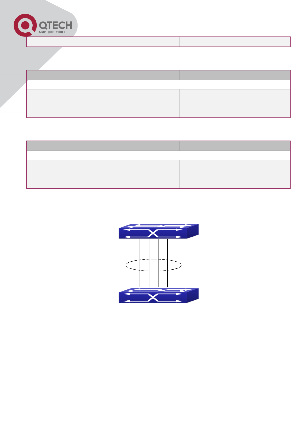
96
the default value.
Command
Explanation
Port mode
lacp port-priority <port-priority>
no lacp port-priority
Set the port priority in LACP protocol.
The no command restores the default
value.
Command
Explanation
Port mode
lacp timeout {short | long}
no lacp timeout
Set the timeout mode in LACP
protocol. The no command restores
the default value.
S1
S2
6. Set the port priority of the current port in LACP protocol
7. Set the timeout mode of the current port in LACP protocol
10.4 Port Channel Examples
Scenario 1: Configuring Port Channel in LACP.
Configure Port Channel in LACP
The switches in the description below are all switch and as shown in the figure, ports 1, 2, 3, 4
of S1 are access ports and add them to group1 with active mode. Ports 6, 8, 9, 10 of S2 are
access ports and add them to group2 with passive mode. All the ports should be connected
with cables.
The configuration steps are listed below:
Switch1#config
+7(495) 797-3311 www.qtech.ru
Москва, Новозаводская ул., 18, стр. 1
Page 98

97
S1
S2
Switch1(config)#interface ethernet 1/1-4
Switch1(Config-If-Port-Range)#port-group 1 mode active
Switch1(Config-If-Port-Range)#exit
Switch1(config)#interface port-channel 1
Switch1(Config-If-Port-Channel1)#
Switch2#config
Switch2(config)#port-group 2
Switch2(config)#interface ethernet 1/6
Switch2(Config-If-Ethernet1/6)#port-group 2 mode passive
Switch2(Config-If-Ethernet1/6)#exit
Switch2(config)#interface ethernet 1/8-10
Switch2(Config-If-Port-Range)#port-group 2 mode passive
Switch2(Config-If-Port-Range)#exit
Switch2(config)#interface port-channel 2
Switch2(Config-If-Port-Channel2)#
Configuration result:
Shell prompts ports aggregated successfully after a while, now ports 1, 2, 3, 4 of S1 form an
aggregated port named “Port-Channel1”, ports 6, 8, 9, 10 of S2 form an aggregated port
named “Port-Channel2”; can be configured in their respective aggregated port mode.
Scenario 2: Configuring Port Channel in ON mode.
Configure Port Channel in ON mode
As shown in the figure, ports 1, 2, 3, 4 of S1 are access ports and add them to group1 with
“on” mode. Ports 6, 8, 9, 10 of S2 are access ports and add them to group2 with “on” mode.
The configuration steps are listed below:
Switch1#config
+7(495) 797-3311 www.qtech.ru
Москва, Новозаводская ул., 18, стр. 1
Page 99

98
Switch1(config)#interface ethernet 1/1
Switch1(Config-If-Ethernet1/1)#port-group 1 mode on
Switch1(Config-If-Ethernet1/1)#exit
Switch1(config)#interface ethernet 1/2
Switch1 (Config-If-Ethernet1/2)#port-group 1 mode on
Switch1 (Config-If-Ethernet1/2)#exit
Switch1 (config)#interface ethernet 1/3
Switch1 (Config-If-Ethernet1/3)#port-group 1 mode on
Switch1 (Config-If-Ethernet1/3)#exit
Switch1 (config)#interface ethernet 1/4
Switch1 (Config-If-Ethernet1/4)#port-group 1 mode on
Switch1 (Config-If-Ethernet1/4)#exit
Switch2#config
Switch2(config)#port-group 2
Switch2(config)#interface ethernet 1/6
Switch2 (Config-If-Ethernet1/6)#port-group 2 mode on
Switch2 (Config-If-Ethernet1/6)#exit
Switch2 (config)#interface ethernet 1/8-10
Switch2(Config-If-Port-Range)#port-group 2 mode on
Switch2(Config-If-Port-Range)#exit
Configuration result:
Add ports 1, 2, 3, 4 of S1 to port-group1 in order, and we can see a group in “on” mode is
completely joined forcedly, switch in other ends won’t exchange LACP PDU to complete
aggregation. Aggregation finishes immediately when the command to add port 1/2 to portgroup 1 is entered, port 1 and port 2 aggregate to be port-channel 1, when port 1/3 joins portgroup 1, port-channel 1 of port 1 and 2 are ungrouped and re-aggregate with port 3 to form
port-channel 1, when port 1/4 joins port-group 1, port-channel 1 of port 1, 2 and 3 are
ungrouped and re-aggregate with port 4 to form port-channel 1. (It should be noted that
whenever a new port joins in an aggregated port group, the group will be ungrouped first and
re-aggregated to form a new group.) Now all four ports in both S1 and S2 are aggregated in
“on” mode and become an aggregated port respectively.
10.5 Port Channel Troubleshooting
If problems occur when configuring port aggregation, please first check the following for
causes.
+7(495) 797-3311 www.qtech.ru
Москва, Новозаводская ул., 18, стр. 1
Page 100

99
Ensure all ports in a port group have the same properties, i.e., whether they are in full-
duplex mode, forced to the same speed, and have the same VLAN properties, etc. If
inconsistency occurs, make corrections.
Some commands cannot be used on a port in port-channel, such as arp, bandwidth, ip,
ip-forward, etc.
+7(495) 797-3311 www.qtech.ru
Москва, Новозаводская ул., 18, стр. 1
 Loading...