

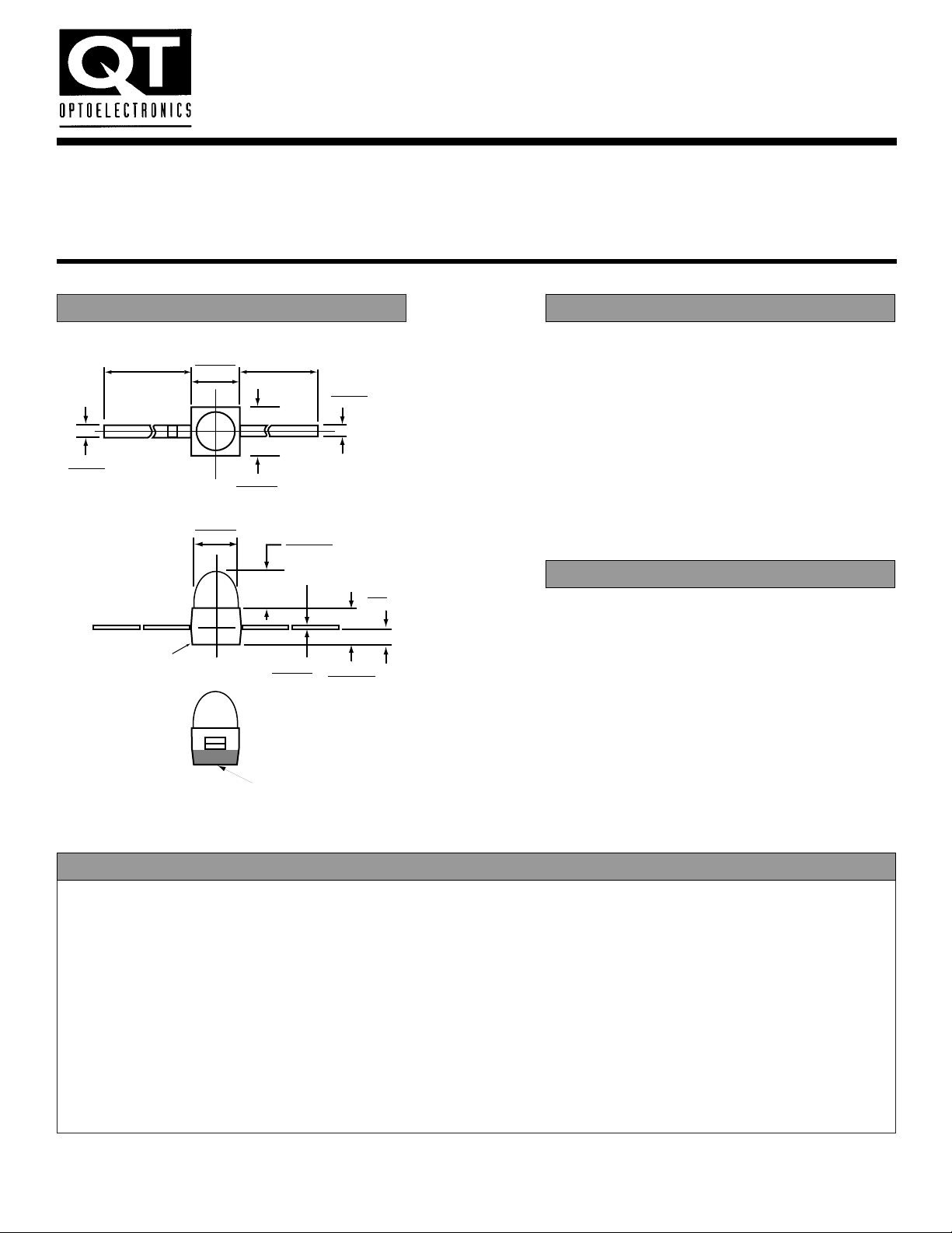
PACKAGE DIMENSIONS DESCRIPTION
The QT Optoelectronics family of T-3/4 subminiature LED lamps feature a square-base, transfer
molded package for surface mount applications.
A tinted diffused or water clear epoxy lens —
available in AIGaAs red, high-efficiency red,
green, and yellow — produces wide-angle beam
emission and sharp on/off contrast. The LEDs are
offered with gullwing lead bends for top mounting,
as well as yoke lead bends and Z-bends for
mounting to the back of a PCB.
■ Subminiature T-3/4 transfer molded
■ Low package profile
■ Axial leads
■ Wide viewing angle
■ SMT versions
FEATURES
SUBMINIATURE T-3/4 LED
DIFFUSED and CLEAR LAMPS
HIGH EFF. RED HLMP-6305A Water Clear MV6700A Diffused
YELLOW HLMP-6405A Water Clear MV6300A Diffused
GREEN HLMP-6505A Water Clear MV6400A Diffused
AIGaAs RED HLMP-Q105A Water Clear HLMP-Q150A Diffused
.031 (.78)
.023 (.58)
.058 (1.48)
.050 (1.28)
.276 (7.0) MIN.276 (7.0) MIN
NOTE:
1. ALL DIMENSIONS ARE IN INCHES (mm)
.056 (1.44)
.048 (1.24)
.010 (.26)
.002 (.06)
CATHODE MARK
.075 (1.9)
.063 (1.6)
.087 (2.2)
.079 (2.0)
.024 (.6)
.016 (.4)
.020 (.5)
.012 (.3)
.091 (2.3)
.083 (2.1)
DIA
CATHODE MARK
TYPE SOURCE COLOR LENS COLOR
HLMP-6305A High Efficiency Red Water Clear
HLMP-6405A Yellow Water Clear
HLMP-6505A Green Water Clear
HLMP-Q105A AIGaAs Red Water Clear
MV6700A High Efficiency Red Red Diffused
MV6300A Yellow Yellow Diffused
MV6400A Green Green Diffused
HLMP-Q150A AIGaAs Red Red Diffused
PHYSICAL CHARACTERISTICS
HLMP- TEST
PART NUMBER QTLP- MV6700A MV6300A MV6400A Q150A CONDITIONS
Luminous intensity (mcd) IF = 10 mA
minimum 1.0 1.0 1.0 1.0*
typical 3.0 3.0 3.0 1.8*
Forward voltage (V) IF = 10 mA
minimum 1.5 1.5 1.5
typical 1.8 2.0 2.0 1.6*
maximum 3.0 3.0 3.0 1.8*
Peak wavelength (nm) 635 583 570 660
Spectral line half width (nm) 40 36 28 20 IR =100 mA
Reverse voltage (V) 5 5 5 5
Viewing angle (°) 50 50 28 50
ELECTRO-OPTICAL CHARACTERISTICS (TA = 25° C Unless otherwise specified)
PARAMETER HLMP-6305A HLMP-6405A HLMP-6505A HLMP-Q105A UNITS
MV6700A MV6300A MV6400A HLMP-Q150A
Power dissipation 135 85 135 85 mW
Average forward current 30 20 30 30 mA
Peak forward current
(1mS pulsewidth, 0.1% DF) 90 60 90 300 mA
Lead soldering time at 260° C 3 3 3 3 sec
Operating temperature -55 to 100 -55 to 100 -55 to 100 -20 to 100 °C
Storage temperature -55 to 100 -55 to 100 -55 to 100 -55 to 100 °C
ABSOLUTE MAXIMUM RATING (TA = 25° C Unless otherwise specified)
HLMP- HLMP- HLMP- HLMP- TEST
PART NUMBER QTLP- 6305A 6405A 6505A Q105A CONDITIONS
Luminous intensity (mcd) IF = 10 mA
minimum 3.0 3.0 3.0 20.0*
typical 12.0 12.0 12.0 50.0*
Forward voltage (V) IF = 10 mA
minimum 1.5 1.5 1.5
typical 1.8 2.0 2.0 1.8*
maximum 3.0 3.0 3.0 2.4*
Peak wavelength (nm) 635 583 570 660
Spectral line half width (nm) 40 36 28 20
Reverse voltage (V) 5 5 5 5 IR =100 mA
Viewing angle (°) 25 25 25 25
ELECTRO-OPTICAL CHARACTERISTICS (TA = 25° C Unless otherwise specified)
SUBMINIATURE T-3/4 LED
DIFFUSED and CLEAR LAMPS
*Tested at
IF= 1 mA
*Tested at
IF= 20 mA

SUBMINIATURE T-3/4 LED
DIFFUSED and CLEAR LAMPS
TYPICAL ELECTRO-OPTICAL CHARACTERISTIC CURVES (TA = 25° C)
GREEN
YELLOW
H-E RED
AIGaAs RED
WAVELENGTH (l) — nm
RELATIVE OUTPUT
520 540 560 580 600 620 640 660 680
120%
100%
80%
60%
40%
20%
0%
700
YELLOW
GREEN
H-E RED
INSTANTANEOUS FORWARD CURRENT I
F
(mA)
LUMINOUS INTENSITY
60 80
40
30
20
10
0
40200
VF — FORWARD VOLTAGE — V
I
F
— FORWARD CURRENT — mA
300.0
200.0
100.0
50.0
20.0
10.0
5.0
2.0
1.0
.5
.2
.1
3.52.51.5 3.01.0.50 2.0
GREEN
H-E RED
YELLOW
AIGaAs
RED
FORWARD VOLTAGE V
F
(VOLTS)
PEAK FORWARD CURRENT I
F
(mA)
100
50
60
80
70
40
30
20
10
0 1 2 3 4
90
FIG. 1 - Forward Current vs. Forward Voltage FIG. 2 - Luminous Intensity vs. Forward Current
FIG. 3 - Forward Current vs. Forward Voltage—AIGaAs
FIG. 4 - Spectral Distribution

DESCRIPTION
These subminiature solid state lamps are transfer molded
in an axial lead package. They are available in yellow,
green, high efficiency red and AIGaAs red in both diffused
and water clear lens.
Automatic placement equipment can be used to mount the
LEDs on the PC board. The lamps can be mounted using
either batch or in line vapor phase reflow solder processes.
■ Available in Gullwing, Yoke and Z-bend lead formings
■ Compatible with automatic placement equipment
■ Compatible with vapor phase reflow soldering processes
■ Long life — solid state reliability
■ Reel and tape or bulk packaging available
FEATURES
SUBMINIATURE T-3/4 LED
DIFFUSED and CLEAR LAMPS
OPTIONAL CONFIGURATIONS
GULLWING LEAD CONFIGURATION
YOKE LEAD CONFIGURATION
Z-BEND LEAD CONFIGURATION
Call QT Optoelectronics for more information or the phone number of your nearest distributor.
United States 800-533-6786 ■France 33 01/43.99.25.12 ■Germany 49 089/96.30.51■United Kingdom 44 01296/39.44.99 ■Asia/Pacific 603/735-2417
NOTE:
ALL DIMENSIONS ARE IN INCHES (mm)
PACKAGE DIMENSIONS
© 1996 QT Optoelectronics QT-009-A
DS 100
ANODE
.020 (.5)
.012 (.3)
.039 (1.0)
.028 (.7)
.115 (2.92)
.099 (2.52)
.016 (.4)
.008 (.2)
.087 (2.2)
.079 (2.0)
.154 (3.90)
.148 (3.75)
.033 (.82)
.000 (.00)
.078 (1.9)
.063 (1.6)
.058 (1.48)
.050 (1.28)
CATHODE MARK
CATHODE
.024 (.6)
.016 (.4)
.091 (2.3)
.083 (2.1)
CATHODE
.010 (.26)
.002 (.06)
.020 (.5)
.012 (.3)
ANODE
.047 (1.2)
.031 (0.8)
.033 (.85)
.026 (.65)
.048 (1.22)
.032 (.82)
.115 (2.92)
.099 (2.52)
.087 (2.2)
.079 (2.0)
.300 (7.62) MAX
.078 (1.9)
.063 (1.6)
CATHODE
CATHODE
.117 (2.96)
.100 (2.56)
.058 (1.48)
.050 (1.28)
CATHODE MARK
.024 (.6)
.016 (.4)
.091(2.3)
.083 (2.1)
.010 (.26)
.002 (.06)
.020 (.5)
.012 (.3)
ANODE CATHODE
.010 (.26)
.002 (.06)
.039 (.99)
.023 (.59)
.240 (1.6)
.232 (5.9)
.087 (2.2)
.079 (2.0)
.189 (4.8)
.173 (4.4)
.128 (3.24)
.112 (2.84)
.078 (1.9)
.063 (1.6)
CATHODE
.033 (.85)
.026(.65)
CATHODE
.091 (2.3)
.083 (2.1)
.024 (.6)
.016 (.4)
.034 (.86)
.026 (.66)
.058 (1.48)
.050 (1.28)
 Loading...