

Page 1
User Manual
Manuel de
l’utilisateur
Bedienhandbuch
Manual del Usuario
• PL218
• PL224
• PL230
• PL236
*TD-000088-00*
TD-000088-00
Rev. B
PL2 Amplifiers
POWERLIGHT 2
1
Page 2
Explanation of
graphical symbols
Explication des
symboles graphiques
Erklärung der
Bildsymbole
Explicación de
símbolos
The lightning flash with arrowhead
symbol, within an equilateral
triangle, is intended to alert the user
to the presence of uninsulated
“dangerous voltage” within the
product’s enclosure that may be of
sufficient magnitude to constitute a
risk of electric shock to humans.
The exclamation point within an
equilateral triangle is intended to
alert the users to the presence of
important operating and
maintenance (servicing) instructions
in the literature accompanying the
product.
Le symbole éclair avec pointe de
flèche à l'intérieur d'un triangle
équilatéral est utilisé pour alerter
l'utilisateur de la présence à
l'intérieur du coffret de "tension nonisolée dangereuse" d'ampleur
suffisante pour constituer un risque
de choc électrique pour l'être
humain.
Le point d'exclamation à l'intérieur
d'un triangle équilatéral est employé
pour alerter les utilisateur de la
présence d'instructions importantes
pour le fonctionnement et l'entretien
(service) dans les documents
accompagnant l'appareil.
Das Blitzzeichen innerhalb eines
gleichseitigen Dreiecks warnt den
Benutzer vor nicht isolierter,
gefährlicher Spannung im Inneren
des Gerätes. Diese Spannung ist
hoch genug, um Personen durch
elektrischen Schlag zu gefährden.
Das Ausrufungszeichen innerhalb
eines gleichseitigen Dreiecks weist
den Benutzer auf wichtige
Bedienungs- und
Wartungsanweisungen hin, die in
den gerätebegleitenden Unterlagen
aufgeführt sind.
El rayo dentro de un tríangulo
equilátero alerta al usuario de la
presencia de voltaje peligroso no
aislado dentro del producto, que
puede tener un nivel suficiente para
constitutuir un riesgo de descarga
eléctrica para el usario.
El signo de exclamación inscrito en
un triángulo equilátero alerta a los
usuarios de la presencia de
instrucciones importantes de
funcionamiento y mantenimiento
(servicio) en la literatura que
acompaña al producto.
CAUTION
RISK OF ELECTRIC SHOCK
DO NOT OPEN
CAUTION: To reduce the risk of
electric shock, do not remove
the cover. No user-serviceable
parts inside. Refer servicing to
qualified service personnel.
WARNING: To prevent fire or
electric shock, do not expose
this equipment to rain or moisture.
2
ATTENTION!
RISQUE DE CHOC ÉLECTRIQUE
NE PAS OUVRIR
ATTENTION: Pour éviter les
risques de choc électrique, ne
pas enlever le couvercle. Cet
appareil ne comporte aucune
pièce pouvant être réparée par
l'utilisateur. Confier l'entretien
à un technicien qualifié.
AVERTISSEMENT: Pour éviter le
risque de choc électrique ou
d'incendie, n'exposez cet
appareil ni à l'humidité excessive ni aux projections d'eau
(pluie, ruissellement, etc …)
VORSICHT: Um Gefährdung
durch elektrischen Schlag zu
vermeiden, darf das Gehäuse
nicht geöffnet werden. Es
befinden sich keine vom
Benutzer reparierbaren Teile im
Inneren des Gerätes. Überlassen Sie jegliche Reparatur
dem qualifizierten Fachmann.
WARNUNG: Um die Gefahr eines
Brandes bzw. eine Verletzung
durch elektrischen Schlag zu
vermeiden, sollten Sie das Gerät
niemals Regen oder Feuchtigkeit aussetzen.
VORSICHT
GEFAHR EINES ELEKTRISCHEN
SCHLAGES. NICHT ÖFFNEN!
PRECAUCIÓN
RIESGO DE DESCARGA ELÉCTRICA.
PRECAUCIÓN: Para reducir el
riesgo de alguna descarga
eléctrica, no quite la tapa. El
usario no debe ajustar los
componentes internos. Para
mantenimiento solicite la ayuda
de personal cualificado.
AVISO: Para evitar un incendio
o una descarga eléctrica, no
exponga este equipo a la lluvia
o humedad.
NO LO ABRA.
Page 3

TABLE OF CONTENTS • TABLE DES MATIÈRES • INHALTSVERZEICHNIS • TABLA DE LAS MATERIAS
Explanation of graphical symbols...................... 2
Explication des symboles graphiques
Erklärung der Bildsymbole
Explicación de símbolos
TABLE OF CONTENTS.............................................. 3
Table des matières
Inhaltsverzeichnis
Tabla de las materias
FCC Interference Statement ................................. 4
INTRODUCTION ........................................5–8
AVANT-PROPOS
EINFÜHRUNG
INTRODUCCIÓN
Front panel .................................................................7
Panneau avant
Vorderseite
Panel frontal
Rear panel .................................................................8
Panneau arrière
Rückseite
Panel posterior
FEATURES & SETUP............................... 9–15
CARACTÉRISTIQUES ET LEUR UTILISATION
AUSSTATTUNG & EINSTELLUNGEN
CARACTERÍSTICAS Y AJUSTES
Clip limiter .................................................................9
Limiteur d'écrêtement
Clip Limiter
Limitador de picos
Input filter ................................................................10
Filtres d'entrée
Eingangsfilter
Filtro de entrada
Parallel input mode ................................................11
Mode entrées parallèles
Eingangsparallelschaltung
Modo de entradas paralelas
Bridge mono mode .......................................... 12-13
Mode ponté mono
Monobrückenbetrieb
Modo puenteado en mono
What are the differences among Stereo,
Parallel Input, and Bridge
Mono modes? .......................................... 14-15
Modes stéréo, parallèle et ponté, quelles sont
les différences?
Unterschiede zwischen Stereo-, Parallel- und
Monobrückenbetrieb
¿Cuáles son las diferencias entre los modos Estéreo,
Entradas Paralelas y Puenteado en Mono?
INSTALLATION ...................................... 16-17
INSTALLATION
EINBAU
INSTALACIÓN
CONNECTIONS ......................................18–22
CONNEXIONS
ANSCHLÜSSE
CONEXIONES
Inputs....................................................................... 18
Entrées
Eingänge
Entradas
Speakon™ outputs ............................................... 20
Sorties Speakon™
Speakon™ Ausgänge
Salidas Speakon™
Binding post outputs ............................................ 21
Bornes à écrou
Anschlussklemmen
Terminales con tornillo
Operating voltage (AC mains) ............................. 22
Tension d’utilisation (alimentation CA)
Netzanschluß
Voltaje de operación (CA principal)
DataPort .................................................................. 22
Port de données
DataPort
Puerto de datos
OPERATION ............................................ 23–26
UTILISATION
BETRIEB
OPERACIÓN
AC power switch .................................................. 23
Interrupteur d'alimentation CA
Netzschalter
Interruptor de encendido
LED indicators ....................................................... 23
Indicateurs DEL
LED-Anzeige
Indicadores LED
Gain controls ......................................................... 23
Contrôles de gain
Verstärkungsregler
Controles de ganancia
Security panel .................................................. 24-25
Panneau de securité
Sicherheitsabdeckung
Panel de seguridad
Fan cooling ............................................................ 26
Ventilation
Lüfterkühlung
Ventilación
Safe operating levels ........................................... 26
Niveaux d'utilisation sécuritaires
Betriebspegel
Niveles adecuados de operación
APPLICATIONS ................................................. 27–29
APPLICATIONS
ANWENDUNGSBEISPIELE
APLICACIONES
TROUBLESHOOTING ....................................... 30–33
DÉPANNAGE
FEHLERBEHEBUNG
SOLUCIÓN DE PROBLEMAS
Problem:
Problem:
Problem:
Problem:
Problem:
Problem:
no sound ........................................... 30-31
Problème:
pas de son
Problem:
kein Ton
Problema:
no hay sonido
distorted sound .................................... 32
Problème:
son distortionné
Problem:
Verzerrungen
Problema:
sonido distorsionado
no channel separation ....................... 32
Problème:
pas de séparation des canaux
Problem:
keine Kanaltrennung
Problema:
no hay separación entre los canales
hum ......................................................... 33
Problème:
ronflement
Problem:
Brummen
Problema:
zumbidos
hiss ......................................................... 33
Problème:
sifflement
Problem:
Rauschen/Zischen
Problema:
ruido (
hiss
)
squeals and feedback ........................ 33
Problème:
bruits et effet Larsen
Problem:
Pfeifen und Rückkopplungen
Problema:
chillidos y retroalimentación
INNER WORKINGS ............................................ 34-35
SOUS LE CAPOT
INNERER AUFBAU
OPERACIÓN INTERNA
SPECIFICATIONS .............................................. 36–37
SPÉCIFICATIONS
TECHNISCHE DATEN
ESPECIFICACIONES
WARRANTY INFORMATION ................................. 38
INFORMATIONS DE GARANTIE
GARANTIE-BEDINGUNGEN
INFORMACIÓN DE GARANTÍA
ADDRESS & TELEPHONE INFORMATION ........... 39
ADRESSE POSTALE ET NUMÉROS
ADRESSE UND TELEFONNUMMERN
DIRECCIÓN Y TELÉFONO
3
3
Page 4

NOTE: This equipment has been tested and found to comply with the limits for a Class B digital device,
pursuant to part 15 of the FCC rules. These limits are designed to provide reasonable protection against harmful
interference in a residential installation. This equipment generates, uses, and can radiate radio frequency
energy and if not installed and used in accordance to the instructions, may cause harmful interference to radio
communications. However, there is no guarantee that interference will not occur in a particular installation. If
this equipment does cause harmful interference to radio or television reception, which can be determined by
turning the equipment off and on, the user is encouraged to try to correct the interference by one or more of the
following measures:
• Reorient or relocate the receiving antenna.
• Increase the separation between the equipment and the receiver.
• Connect the equipment into an outlet on a circuit different from that to which the receiver is connected.
• Consult the dealer or an experienced radio/TV technician for help.
4
Page 5
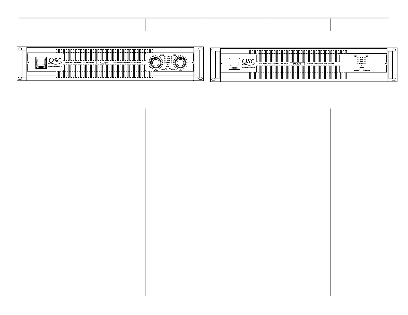
Left: the front panel of a POWERLIGHT 2 amplifier
A gauche: le panneau avant d’un amplificateur POWERLIGHT 2
Links: die Vorderseite eines POWERLIGHT 2-Verstärkers
Izquierda: el panel frontal de un amplificador POWERLIGHT 2
Right: a POWERLIGHT 2 amplifier with security panel installed
A droite: le panneau avant avec plaquette protectrice installée
Rechts: ein POWERLIGHT 2-Verstärker mit Sicherheitsabdeckung
Derecha: un amplificador PL2 con el panel de seguridad instalado
INTRODUCTION
Thank you for the purchase of
your new PowerLight 2
amplifier. To get the most out of
your amplifier, review this manual
carefully. The installation and
operation sections provide proper
connection and operation guidelines.
The PL2 continues the PowerLight
tradition of offering the finest
combination of high fidelity and
reliability available. Visually, the PL2
is easily identifiable as a member of
the PowerLight family. Yet, the PL2
has an expanded feature set
designed to meet the demands of
the touring professional.
EINFÜ HRUNG
INTRODUCCIÓ NAVANT-PROPOS
© Copyright 2000, QSC Audio Products, Inc.
QSC® is a registered trademark, and PowerWave™ is a trademark, of QSC Audio
Products, Inc.
“QSC” and the QSC logo are registered with the U.S. Patent and Trademark
Office.
All other trademarks are the property of their respective owners.
•
Improved Power Supply
The PL2 power supply delivers 1200
watts more power than the original
PowerLight. The front end of the
supply has 50% more energy
storage while the back end storage
has increased by 236%. A regulated
“housekeeping” supply has been
added and switching losses have
been reduced. These changes result
in a more efficient energy transfer to
the output stage even during heavy
loads and low AC line conditions.
5
5
Page 6

INTRODUCTION AVANT-PROPOS E I N F Ü HRUNG INTRODUCCIÓ N
•
Improved Clipping Behavior
The smoother clipping behavior of
the PL2 produces fewer high
frequency artifacts than previous
models. This reduces listening stress
at high output levels.
•
New Output and Input
Connectors
Neutrik Speakons have been added
for additional output flexibility. 5way binding posts are also provided.
The combination XLR/TRS input
jacks have been replaced by
separate heavy duty XLR jacks, 1/4
inch TRS jacks and 3-pin terminal
block connectors. All inputs are
wired in parallel to offer easy signal
distribution between amplifiers. A
Dataport connection offers superior
flexibility by interfacing with new
amplifier accessories and distributed
sound networks.
•
Selectable Low-Frequency
Filter
Each channel has its own selectable
LF filter. This filter attenuates the
signal level of frequencies beneath
30 or 50 Hz and allows the
amplifier to be optimized to the
speaker system. When the filter is
switched off, the input rolls off at 5 Hz
to protect from DC inputs.
•
New Power Cord Retaining
Clip!
The PL2 comes with an accesory clip
for the power cord that prevents
accidental power cord disconnection.
This ingenious little clip will insure
the power keeps flowing.
Your new PowerLight 2 amplifier will
give you years of dependable, highperformance audio.
6
Page 7
INTRODUCTION
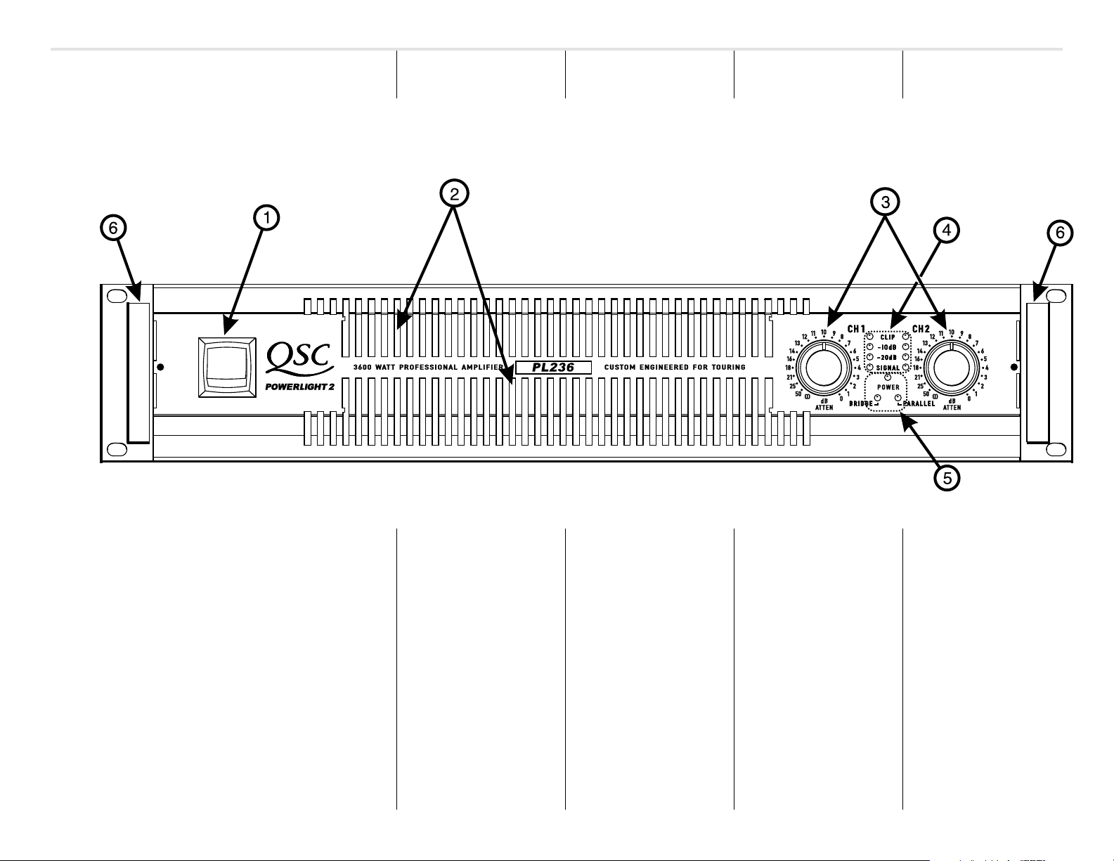
POWERLIGHT 2 Front Panel
EINFÜ HRUNG
INTRODUCCIÓ NAVANT-PROPOS
Front panel
1. Power switch
2. Cooling vents
3. Gain control (1 per channel)
4.
CLIP, -10 dB, -20 dB
SIGNAL
indicator LEDs, 1 per
channel
5.
POWER, BRIDGE
PARALLEL
6. Handles
and
, and
indicator LEDs
Panneau avant
1. Commande marche/arrêt
2. Bouches de ventilation
3. Commande de gain (1 par canal)
4. DELs
CLIP
-20 dB
canaux)
5. DELs
POWER
BRIDGE
PARALLEL
6. Poignées
(écrêtage),
, et
SIGNAL
(mode mono ponté), et
-10 dB
(tous les
(alimentation),
(entrées parallèles)
Vorderseite
1. Netzschalter
2. Abluftöffnungen
3. Pegelsteller (1 pro Kanal)
,
4. LED-Anzeige für
-20 dB
Kanäle)
5. LED-Anzeige für
BRIDGE
und
PARALLEL
(Eingangsparallelschaltung)
6. Griffe
CLIP, -10 dB
und
SIGNAL
(alle
POWER
(Betrieb),
(Mono-Brückenschaltung)
Panel frontal
1. Interruptor de encendido
2. Rejillas de ventilación
3. Control de ganancia (1 por canal)
4. Indicadores LED para
,
-10 dB, -20 dB
todos los canales)
5. Indicadores LED de
(encendido),
(puenteado en mono) y
PARALLEL
6. Asas
BRIDGE
(entradas paralelas)
y
SIGNAL
POWER
CLIP
,
(en
7
7
Page 8
INTRODUCTION
EINFÜ HRUNG
INTRODUCCIÓ NAVANT-PROPOS
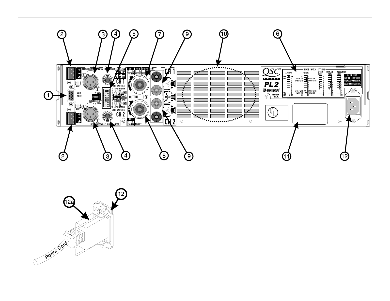
POWERLIGHT 2 Rear Panel
Rear panel
1. DataPort
2. Terminal block inputs
3. XLR inputs
4. TRS inputs
5. Configuration switch
6. Configuration switch chart
7. Speakon output, Channel 1
plus Channel 2 (4-wire)
8. Speakon output, Channel 2
9. Binding post outputs
10. Cooling air inlet vents
11. Serial number label
12. IEC connector for AC power cord
12a. Power cord retaining clip (install
on item 12)
8
Panneau arrière
1. DataPort (port de données)
2. Entrées sur blocs détachables
3. Entrées XLR
4. Entrées TRS
5. Sélecteur de configuration
6. Diagramme au sélecteur de
configuration
7. Sortie Speakon, Canal 1 plus
Canal 2 (4-fils)
8. Sortie Speakon (Canal 2)
9. Sorties sur bornes à écrou
10. Bouches de ventilation
11. Étiquette du numéro en série
12. Connecteur IEC pour cordon
d'alimentaion
12a.
Rückseite
1. DataPort
2. Euroblock (Phönix)
Anschlußstecker
3. XLR-Eingänge
4. Stereoklinken
5. Konfigurationsschalter
6. Erläuterung des
Konfigurationsschalters
7. Speakon-Ausgang, Kanal 1 mit
Kanal 2
8. Speakon-Ausgang (Kanal 2)
9. Anschlussklemmen
10. Lufteinlaßöffnung
11. Seriennummer
12. IEC Kaltgeräteanschluß
12a.
Panel posterior
1. DataPort (puerto de datos)
2. Entradas terminales de bloque
3. Entradas XLR
4. Entradas TRS
5. Selector de configuración
6. Esquema del selector de
configuración
7. Salida Speakon (canal 1 y
canal 2) (4 cables)
8. Salida Speakon (Canal 2)
9. Salidas de sujeción
10. Rejillas de ventilación
11. Etiqueta del número de serie
12. Conector IEC para cable de
poder CA
12a.
Page 9
FEATURES & SETUP CARACTERÍSTICAS
CARACTÉRISTIQUES
AUSSTATTUNG &
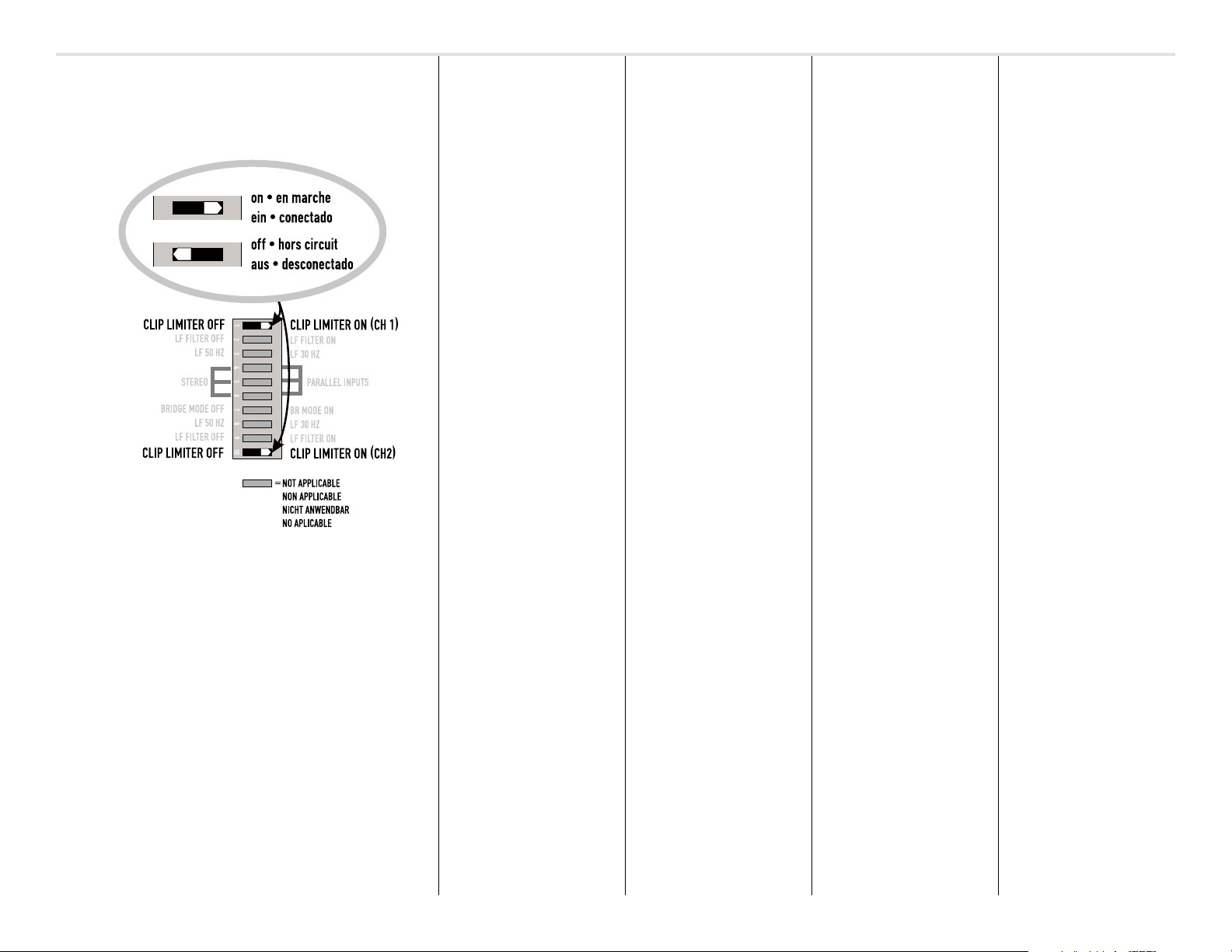
Clip Limiter Configuration
Switch Settings
Clip limiter
DESCRIPTION
When the audio signal drives the
amp's output circuit beyond its power
capability, the amp clips and flattens
the peaks of the waveform. The clip
limiter detects this and quickly
reduces the gain to minimize the
amount of overdrive. To preserve as
much of the program dynamics as
possible, limiting occurs only during
actual clipping.
Each channel has its own clip limiter
that can be switched on or off
independently, as shown at left.
WHEN TO USE IT
When driving full-range speakers,
clip limiting reduces high frequency
distortion caused by bass overloads.
It also protects high frequency
drivers from excess overdrive and
harsh clipping harmonics.
We recommend using the clip
limiters in all applications.
ET LEUR UTILISATION
Limiteur d'écrêtement
DESCRIPTION
Quand le signal audio dépasse la
capacité de puissance du circuit de
sortie de l'amplificateur, le signal est
écrêté, tronquant les pointes de la
forme d'onde. Le circuit limiteur
d'écrêtement détecte cette condition
et réduit rapidement le gain de
l'amplificateur pour minimiser la
surtension. Afin de préserver le
maximum de la dynamique du signal,
le limiteur ne reste en fonction que
pour la durée de l'écrêtement.
Chaque canal est muni de son propre
limiteur, que vous pouvez activer et
désactiver indépendamment, tel
qu'illustré à gauche.
UTILISATION
Lors de l'utilisation de l'amplificateur
avec un signal plein registre, le circuit
limiteur réduit la distorsion des hautes
fréquences causée par les surtensions
des basses fréquences. Le circuit
protège aussi les haut-parleurs de
hautes fréquences des surtensions et
des harmoniques dues aux écrêtements.
Nous recommandons l'urilisation des
limiteurs pour toutes les applications.
EINSTELLUNGEN
Clip Limiter
BESCHREIBUNG
Wenn das Audiosignal die Ausgangsverstärker übersteuert, wird das Signal
geklippt, was zu einer Abflachung der
Wellenspitzen führt. Der Clip Limiter
(Spitzenbegrenzer) erkennt dies und
verringert schnell die Verstärkung um
die Stärke der Übersteuerung zu
reduzieren. Um dabei gleichzeitig aber
soviel Dynamik als möglich zu erhalten,
spricht der Spitzenbegrenzer nur
während echter Übersteuerungen an.
Jeder Kanal hat seinen eigenen Limiter,
der wahlweise zu- oder abgeschaltet
werden kann (siehe Zeichnung).
EINSATZ DES LIMITERS
Bei der Verwendung von BreitbandLautsprechersystemen reduziert der
Einsatz eines Spitzenbegrenzers die
Hochfrequenzverzerrungen, welche von
Übersteuerungen im Bassbereich verursacht werden. Außerdem werden die
Höhentreiber vor Übersteuerung und
hart geklippten Harmonischen geschützt.
Wir empfehlen die Verwendung
eines Spitzenbegrenzers für alle
applikationen.
Y AJUSTES
Limitador de picos
DESCRIPCIÓN
Cuando la señal de audio estimula el
circuito de salida del amplificador más
allá de su capacidad de potencia se
satura con los picos de la forma de
onda. El limitador de picos detecta este
fenómeno y rápidamente reduce la
ganancia para minimizar la cantidad de
sobresaturación. Para conservar las
dinámicas del programa al máximo,
la limitación sólo ocurrira durante el
instante mismo de la saturación.
Cada canal tiene su propio limitador
de picos, usted los puede activar o
desactivar independientemente,
como se muestra a la izquierda.
¿CUÁNDO USARLO?
Cuando se usan bocinas de rango
completo, el limitador de picos reduce
la distorsión de las frecuencias agudas
causada por la sobrecarga de graves.
También protege a los drivers de frecuencias agudas del exceso de saturación y armónicos descontrolados.
Recomendamos usar los limitadores de
clip para todas las aplicaciones.
CAUTION: Clip limiting reduces
extreme overdrive peaks,
allowing a higher average signal
level without audible distortion.
However, increasing the gain
with the clip limiter engaged, until
clipping is again audible, can
double the average output power.
Be careful not to exceed the
power rating of your speakers.
ATTENTION; le circuit de limiteur
d'écrêtement réduit les pointes
de surtension, augmentant le
niveau moyen du signal sans
distortion audible. On peut ainsi
facilement doubler la puissance
moyenne livrée aux hautparleurs. Il faut prendre soin
de ne pas excéder la puissance
admissible des haut-parleurs.
ACHTUNG: Der Einsatz eines
Spitzenbegrenzers ermöglicht
eine höheres Durchschnittssignal ohne hörbare Verzerrungen. Eine Erhöhung der
Verstärkung mit eingeschaltetem Clip Limiter kann die durchschnittliche Ausgangsleistung
auf das Doppelte erhöhen. Bitte
achten Sie daher darauf, die
Leistungsangaben Ihrer Lautsprecher nicht zu überschreiten.
ADVERTENCIA: El limitador de
picos reduce señales extremas
de saturación, permitiendo un
nivel de señal más alto sin
distorsión audible. Sin embargo,
aumentar la ganancia con el
limitador de picos activado
puede doblar la capacidad de
salida. Tenga cuidado de no
rebasar el límite de potencia
de sus bocinas.
9
9
Page 10
FEATURES & SETUP
CARACTÉRISTIQUES
AUSSTATTUNG &
CARACTERÍSTICAS
Y AJUSTES
Filtro de entrada
DESCRIPCIÓN
El filtro de frecuencias graves (LF) le
permite atenuar señales abajo de los
30 Hz ó 50 Hz. Esto mejora el
rendimiento de las frecuencias graves
limitando una porción de audio no
audible que mueve el cono, dejando
más potencia disponible para el
rango de frecuencia de las bocinas.
Los ajustes del filtro para cada canal
se controlan individualmente con el
interruptor tipo DIP, como se describe.
Un atenuador de 5 Hz ofrece protección
contra DC o entradas de frecuencias
ultragraves cuando se apaga el filtro.
¿CUÁNDO USARLO?
Por regla, sus bocinas sonarán mejor
con el filtro apropiado. A menos que
anteriormente haya utilizado otro
aparato para filtrar y haya igualado las
frecuencias graves de sus bocinas. Las
bocinas con ventilación (como la bass
reflex, ported, etc …) son especialmente sensibles al desplazamiento
exagerado de los conos causado por
frecuencias por debajo de su límite.
Los filtros de 50 Hz funcionan bien con
la mayoría de bocinas compactas de
rango completo, como sistemas
suround. Tiene un pequeño aumento en
100 Hz para hacerlo mas completo.
El filtro de 30 Hz está pensado para
woofers y para bocinas de alto
rendimiento con rejillas. La posición
de apagado (off) debe ser usada
únicamente para sistemas de subwoofers capaces de una respuesta
inferior a los 30 Hz, o si procesadores
posteriores, como crossovers,
ofrecen filtros apropiados.
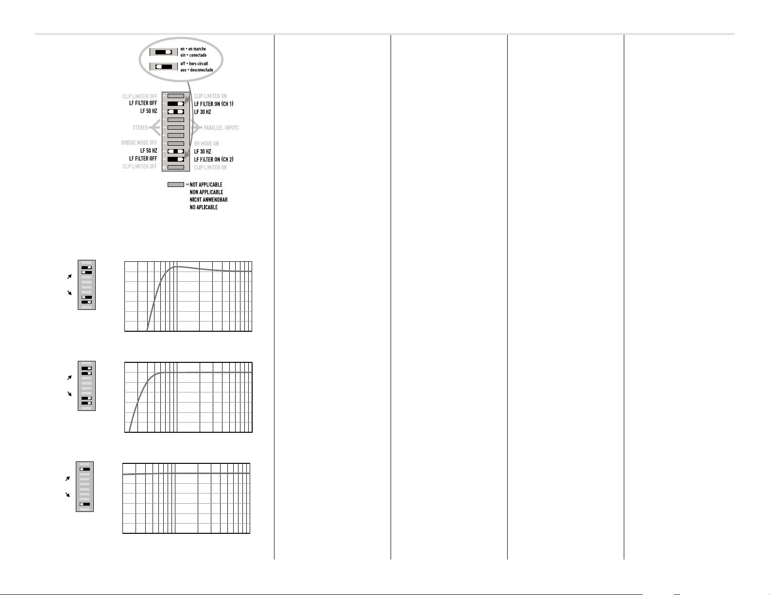
Input Filter Selection Switch Settings
Ch. 1
Ch. 2
1234567891012345678910
50 HZ
50 HZ
LF ON
LF ON
0 dB
+1
-1
-2
-3
-4
-5
-6
80 1 kHz50050 30030 60
100 20020 Hz 40040
LF Filter Frequency Response- 50 Hertz filter on
1234567891012345678910
Ch. 1
Ch. 2
LF ON
30 HZ
30 HZ
LF ON
0 dB
+1
-1
-2
-3
-4
-5
-6
80 1 kHz50050 30030 60
100 20020 Hz 40040
LF Filter Frequency Response- 30 Hertz filter on
12345678910
Ch. 1
Ch. 2
LF OFF
LF OFF
12345678910
0 dB
+1
-1
-2
-3
-4
-5
-6
80 1 kHz50050 30030 60
100 20020 Hz 40040
LF Filter Frequency Response- filter off
Input filter
DESCRIPTION
The low-frequency (LF) filter rolls off
signals below either 30 Hz or 50 Hz.
This improves bass performance by
limiting sub-audio cone motion,
making more power available for the
speaker's rated frequency range.
The filter settings for each channel are
controlled individually through the DIP
switch settings shown. When the filter
is turned off, a 5 Hz rolloff protects
against DC or deep sub-audio inputs.
WHEN TO USE IT
As a rule, your speakers will sound
better with proper filtering. Unless
you already have filtering in a
preceding device, match the setting
to the low frequency rating of your
speakers. Vented (bass reflex,
ported, etc.) speakers are especially
sensitive to cone over-excursion at
frequencies below their rated limit.
The 50 Hz filter works well with most
compact full-range speakers. It has a
slight boost at 100 Hz for greater
fullness. The 30 Hz filter is intended for
woofers and large full-range
speakers. The "off" position should
be used only for subwoofer systems
capable of response below 30 Hz, or if
preceding devices such as crossovers
already provide adequate filtering.
ET LEUR UTILISATION
Filtres d'entrée
DESCRIPTION
Le filtre passe-haut, lorsqu'activé, réduit
le niveau de signal sous 30 Hz ou 50 Hz.
Ce filtre améliore la performance du
système en limitant le mouvement
excessif du cône du haut-parleur de
basses à des fréquences infrasoniques,
donnant plus de puissance
disponible dans le spectre audible.
Les ajustements des filtres pour chaque
canal se font séparément sur les
interrupteurs tel que montré ci-contre.
Lorsque les filtres sont désactivés, un
filtre passe-haut à 5 Hz entre en
fonction afin de protéger le hautparleur contre les tensions continues,
et contre les signaux infrasoniques.
UTILISATION
En règle générale, les haut-parleurs
fonctionnent mieux avec un filtre
bien ajusté. A moins que d'autres
équipements en amont dans la
chaîne soient munis de filtre, ajustez
le filtre de votre amplificateur en
accord avec votre haut-parleur. Les
enceintes à évent (bass reflex, etc)
sont particulièrement sensibles aux
surexcursion des cônes aux
fréquences inférieures à la
fréquence d'accord de l'enceinte.
Le filtre à 50 Hz fonctionne bien avec la
majorité des enceintes compactes, tel
les haut-parleurs de surround. Le filtre
fournit une légère hausse autour de
100 Hz, ce qui donne un son plus plein.
Le filtre à 30 Hz est conçu pour les
enceintes de basses et pour les hautparleurs principaux derrière l’écran. La
position “dérivation” ne devrait ètre
utilisée qu’avec des haut-parleurs
conçus pour reproduire les signaux
sous 30 Hz, ou encore si un autre
appareil dans a cha”ne est muni d’un
filtre adéquat.
EINSTELLUNGEN
Eingangsfilter
BESCHREIBUNG
Ein LF- oder Hochpassfilter schneidet
Frequenzen unterhalb 30 Hz, bzw. 50 Hz
ab. Hierdurch wird die Basswiedergabe verbessert, da ultratiefe, störende
Frequenzen abgeschnitten werden, und
hierdurch mehr Leistung für die normale
Wiedergabe zur Verfügung steht.
Die Filtereinstellungen werden durch
den links abgebildeten DIP-Schalter
eingestellt. Bei abgeschaltetem Filter
werden die Frequenzen unterhalb
5 Hz unterdrückt, damit ein Schutz
von Gleichspannung und
Infraschallanteilen besteht.
EINSATZ DES EINGANGSFILTERS
In der Regel werden Ihre Lautsprecher
bei richtiger Filterung besser klingen.
Falls nicht schon an anderer Stelle eine
entsprechende Filterung stattgefunden
hat, stellen Sie die Filterung entsprechend dem Frequenzgang Ihrer Lautsprecher ein. Belüftete Lautsprecher
(z.B. Bassreflex, etc.) sind ausgesprochen empfindlich gegen zu große
Auslenkungen der Membran unterhalb
des spezifizierten Frequenzbereichs.
Der 50 Hz Hochpass arbeitet zufriedenstellend mit den meisten Breitbandlautsprechern, wie sie in Surroundsystemeneingesetzt werden. Er weist
eine leichte Überhöhung bei 100 Hz
auf um einen klanglich volleren Eindruck
zu erzeugen. Das 30 Hz Filter ist für
Woofer und große Breitbandsysteme
gedacht. Die Schalterstellung “OFF”
sollte nur zusammen mit Subwoofer
Systemen verwendet werden, die
tiefere Frequenzen als 30 Hz
verarbeiten können, oder falls eine
entsprechende Filterung in den
vorgeschalteten Frequenzweichen
vorgenommen wurde.
10
Page 11
FEATURES & SETUP
CARACTÉRISTIQUES
AUSSTATTUNG &
CARACTERÍSTICAS
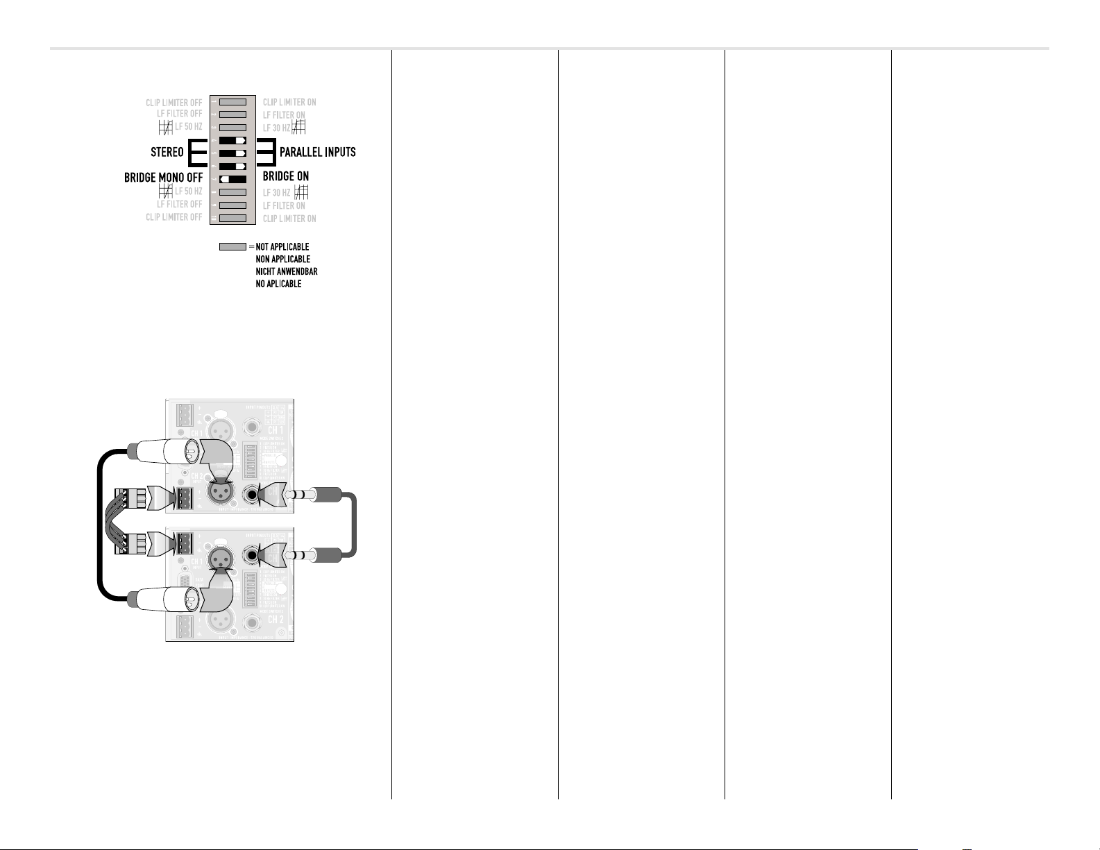
Mode Selection Switch Location and Settings
"Daisy-Chaining" upper amplifier's input signal
to lower amplifier's input. Use one of the connection
methods shown (XLR, 1/4 "TRS or terminal block).
Parallel input mode
DESCRIPTION
The "Parallel Input" switches let you
operate the amplifier in parallel
mode, delivering the same signal to
two channels without using a
Y-cable. Each channel drives its own
speaker load, with independent gain,
filtering, and clip limiting.
Set switch positions 4, 5, and 6
to couple the inputs together.
the switches off for stereo,
bi-amping, or other 2-channel
modes.
The orange
LED indicator on the front panel
warns you when the switches are set
to parallel.
1 SIGNAL INTO 2 CHANNELS
Parallel the inputs when you need to
drive two amp channels with one
input signal
keeping separate control of both
channels' gain, filtering, and limiting.
(parallel mode)
Branching to other amps
In addition to parallel mode, you can
parallel the inputs in
mode
to carry the signal to additional
amplifiers through the unused extra
input jacks. This is often called a
"daisy-chain." See page 14 for an
explanation of amp operating
modes.
NOTE: If you're using a
balanced signal, use only
balanced patch cables; even
one unbalanced cable will
unbalance the entire signal
chain, possibly causing hum.
NOTE: Turn off the "Parallel
Inputs" switches when
feeding two separate signals
to the two channels.
"ON"
Turn
PARALLEL
while
bridged mono
ET LEUR UTILISATION
Mode entrées parallèles
DESCRIPTION
Les interrupteurs "Parallel Inputs" vous
permettent d'utiliser l'amplificateur
en mode parallèle, où le même signal
est livré aux deux canaux sans avoir
à utiliser un câble "Y". Chaque canal
amplifie le signal indépendamment,
avec ajustements propres de gain,
de filtre, et de limiteur.
Ajustez les interrupteurs 4, 5, et 6 en
position "on" pour joindre les entrées des
deux canaux. Laissez les interrupteurs
en position "off" pour utilisation en
mode stéréo, bi-amplification, ou toute
autre application 2 canaux. La DEL
jaune
PARALLEL
allume pour indiquer que l'amplificateur
est réglé en mode parallèle.
1 SIGNAL —> 2 CANAUX
Joignez les entrées (mode parallèle)
quand vous voulez contrôler deux
haut-parleurs avec des ajustements
spécifiques de gain, de filtre et de
limiteur à partir d'un même signal,
comme dans un système
ambiophonique (surround).
NOTE; désengager les interrupteurs "parallel inputs"
quand vous amenez des signaux
différents aux deux canaux.
sur le panneau avant
EINSTELLUNGEN
Parallelbetrieb
BESCHREIBUNG
Durch die "Parallel Input" Schalter kann
der Verstärker parallel betrieben werden,
wobei das gleiche Signal beiden Kanälen
zugeführt wird. Jeder Verstärkerkanal
treibt dabei seinen eigenen Lautsprecher
mit unabhängiger Verstärkung,
Filterung und Spitzenbegrenzung.
Stellen Sie die Schalterpositionen 4,
5 und 6 auf "ON" um die Eingänge zu
verkoppeln. Schalten Sie die Schalter
aus für Stereo-, Bi-Amping- oder einen
anderen 2-Kanalbetrieb. Die gelbe
PARALLEL
leuchtet auf, wenn Parallelbetrieb
gewählt wurde.
Mit parallelgeschalteten Eingängen
können die anderen Eingangsstecker
benutzt werden, um das Signal an
weitere Verstärker zu liefern.
1 SIGNAL —> 2 KANÄLE
Schalten Sie die Eingänge parallel,
wenn zwei Lautsprecher mit einem
Signal angefahren, und dabei aber
separate Verstärkung, Filterung oder
Begrenzung benutzt werden soll.
BITTE BEACHTEN SIE: Wenn Sie
ein symmetrisches Eingangssignal anlegen, benutzen Sie auch
ausschließlich symmetrische
Kabel zur Weiterverbindung, da
auch nur ein einziges unsymmetrisches Kabel das Gesamtsignal
unsymmetrisch werden läßt,
was möglicherweise Brummen
verursachen kann.
BITTE BEACHTEN SIE: Schalten
Sie den Parallelbetrieb aus,
wenn zwei separate Signale
eingespeist werden sollen.
-LED auf der Frontplatte
Y AJUSTES
Modo de entradas paralelas
¿QUÉ ES?
El interruptor "Parallel Input" le permite
operar el amplificador en modo
paralelo, enviando la misma señal
hacia ambos canales sin necesidad
de utilizar un cable tipo "Y". Cada
canal controla su propia carga de
bocinas, con ganancia independiente,
filtros y limitador de picos.
Ajuste los selectores 4, 5 y 6 en la
posición de "ON", para acoplar las
entradas. Coloque los interruptores
en la posición de "OFF" para trabajar
en el modo estéreo, biamplificado, o
cualquier otro modo de 2 canales. El
indicador LED amarillo para el modo
PARALLEL
advierte cuando el interruptor ha
sido ajustado en el modo paralelo.
1 SEÑAL —> 2 CANALES
Utilice la entrada paralela cuando se
alimentan dos bocinas con una sola
señal de entrada (modo paralelo)
mientras se mantiene control por
separado de la ganancia, los filtros y
la limitación de ambos canales. Use
el modo "puenteado" en mono para
conectar la señal a amplificadores
adicionales por medio de los
conectores extra de entrada.
NOTA: Si usa una señal balanceada, utilice únicamente
cables adecuados. Un solo
cable no balanceado puede
afectar el recorrido de la
señal y producir zumbidos.
NOTA: Cuando alimente el
amplificador con dos señales
independientes, coloque el
interruptor "Parallel Inputs" en
la posición de apagado—"Off".
del panel frontal, le
11
11
Page 12
FEATURES & SETUP
CARACTÉRISTIQUES
AUSSTATTUNG &
CARACTERÍSTICAS
Setting DIP switch #7 for bridge mono operation
Setting DIP switches #4, 5 and 6 so that channel 1's
input is available for "daisy-chaining" on channel
2's input connectors.
Bridge mono mode
DESCRIPTION
Bridged mono mode combines the
power of both amplifier channels into
one speaker load, resulting in twice
the voltage swing, four times the
peak power, and approximately three
times the sustained power of a
single channel. This mode uses the
input, gain control, input filter, and
clip limiter of Channel 1; Channel 2's
filter and limiter have no effect.
The yellow
front panel indicates when the amp
is in bridged mono mode.
WHEN TO USE IT
Use bridged mono to deliver the power
of two channels to a
4-ohm load, such as a subwoofer.
Set switch position 7 to
ON
connect the speaker as shown.
Using the parallel inputs and bridge
mono together will illuminate both
the yellow
PARALLEL
BRIDGE
LED on the
single
8- or
BRIDGE
. Use Channel 1's input, and
BRIDGE
and orange
LEDs on the front panel.
ET LEUR UTILISATION
Mode ponté mono
DESCRIPTION
Le mode ponté mono combine la
puissance de deux canaux de
l'amplificateur (canaux 1 et 2) pour
utilisation sur une seule charge de
hautparleur, doublant ainsi le
tension, quadruplant la puissance de
crête, et donnant environ trois fois la
puissance continue par rapport à un
canal simple. En mode ponté, utiliser
l'entrée, le contrôle de gain, le filtre
et le limiteur du canal 1, les contrôle
du canal 2 étant sans effet.
La DEL
BRIDGE
avant allume pour indiquer que
l'amplificateur est réglé en mode
ponté mono.
UTILISATION
Utilisez le mode ponté mono pour
amener la puissance de deux des
canaux sur une seule charge de 8 ou 4
ohms, tel un haut-parleur de sousgraves. Ajustez l'interrupteur 7 en
position "on". Utilisez l'entrée du canal
1 et branchez la charge tel qu'indiqué
ci-contre.
sur le panneau
EINSTELLUNGEN
Monobrückenbetrieb
BESCHREIBUNG
Monobrückenbetrieb vereint die
Leistung von zwei Verstärkerkanälen
(Kanal 1 & 2, und/oder 3 & 4) in eine
Lautsprecherlast, resultierend in
doppelter Verstärkerspannung,
vervierfachter Spitzenleistung, und
etwa verdreifachter Dauerleistung
eines einzelnen Kanals. Dieser
Modus benutzt den Eingang, den
Verstärkungsregler, den
Eingangsfilter und den Clip Limiter
von Kanal 1 oder Kanal 3. Die
entsprechenden Komponenten von
Kanal 2 und/oder Kanal 4 werden
nicht benutzt.
Die „BRIDGE"-LED auf der
Frontplatte leuchtet im
Monobrückenbetrieb auf.
ANWENDUNG
Sie benötigen diese Anwendung,
wenn Sie die Leistung von zwei
Kanälen auf eine einzelne 8- oder 4
Ohm Last geben wollen, z.B. auf
einen Subwoofer.
Schalter Nr. 7 auf Bridge Mode On.
Benutzen Sie den Eingang von
Kanal 1, und verbinden Sie den
Lautsprecher wie gezeigt.
Y AJUSTES
Modo puenteado en mono
¿QUÉ ES?
El modo puenteado en mono combina
la potencia de dos canales de
amplificador (canales 1 y 2 y/ó 3 y 4 )
hacia una bocina, aumentando dos
veces el consumo de voltaje, cuatro
veces la potencia de picos y
aproximadamente tres veces la
potencia de sostenimiento de un solo
canal. Este modo utiliza la entrada, el
control de ganancia, filtro y limitador
del canal 1 (ó canal 3). Los controles del
canal 2 ó el 4 no producen ningún efecto.
El LED marcado BRIDGE en el panel
frontal, indica la posición del
amplificador en el modo
"puenteado" en mono.
¿CUÁNDO (O CUÁNDO NO)
USARLO?
Utilice el modo puenteado en mono
para pasar la potencia de dos
canales, a una sola carga de 8 ó 4
ohmios. Ajuste el selector número 7
en la posición "BRIDGE MONO ON".
Use las entradas del canal 1 y
conecte la bocina como se muestra
en la figura.
12
12
Page 13

FEATURES & SETUP
CARACTÉRISTIQUES
AUSSTATTUNG &
CARACTERÍSTICAS
Bridged mono output connection uses channel 1's Speakon only
• Mono ponté • Monobrückenbetrieb • Mono puente
Bridge mono mode
(continued)
BRIDGE MONO OUTPUT
CONNECTION-
Note that speaker connection for
bridge mono mode is different than
other modes. The illustrations to the
left show proper bridge mono
connections for both Speakon and
binding post connectors.
ET LEUR UTILISATION
Mode ponté mono
(suite)
EINSTELLUNGEN
Monobrückenbetrieb
(Fortsetzung)
Y AJUSTES
Modo puenteado en
mono (continuación)
Bridge mono operation- Binding post output connection uses
Ch.1 and Ch.2 "+" terminals.
BRIDGED-MONO PRECAUTIONS:
This mode puts a high demand
on the amplifier and speaker.
Excessive clipping may cause
protective muting or speaker
damage. Ensure the speaker
has a sufficient power rating.
Output voltages greater than
100 volts rms are available
between the amplifier's
bridged terminals. CLASS 3
wiring methods, as specified
in accordance with national
(NEC) and local codes, must be
used to connect the speaker.
PRÉCAUTIONS EN MODE
MONO PONTÉ:
Le mode ponté mono place un
stress supplémentaire sur
l'amplificateur et le haut-parleur.
L'écrêtage excessif peut causer
la mise en sourdine par le
circuit de protection et/ou peut
endommager le haut-parleur.
Veuillez vous assurer que le
haut-parleur peut accepter la
puissance de l'amplificateur.
Des pointes de tension de plus
de 100 Vrms sont possibles
entre les bornes de sortie de
l'amplificateur en mode ponté
mono. Installez votre système
selon les codes électriques
local et national du site
d'installation.
BRÜCKENBETRIEB
VORSICHTSMAßNAHMEN:
Diese Betriebsart stellt hohe Anforderungen an Verstärker und
Lautsprecher. Übermäßige Übersteuerung kann zu Abschalten
des Verstärkers oder auch
Lautsprecherbeschädigungen
führen. Stellen Sie sicher, daß
der Lautsprecher entsprechende
Leistungen verarbeiten kann.
Ausgangsspannungen von mehr
als 100 Volt rms liegen zwischen
den Ausgangsanschlüssen an.
Daher müssen die einschlägigen
Sicherheitsmaßnahmen beim
Anschluß der Lautsprecher
beachtet werden.
PRECAUCIONES DEL MODO
PUENTEADO EN MONO
Este modo implica un gran
requerimiento para el amplificador y las bocinas. La
saturación excesiva puede
provocar un silencio para
proteger de cualquier daño a
la bocina. Asegúrese de que
ésta tenga el rango de
potencia necesario.
Los voltajes de salida mayores
a 100 voltios RMS están
disponibles entre las
terminales "puenteadas" del
amplificador. Los métodos de
conexión CLASS 3 (NEC), se
especifican de acuerdo a los
códigos locales o nacionales,
y deben utilizarse para
conectar la bocina.
13
Page 14

FEATURES & SETUP
CARACTÉRISTIQUES
AUSSTATTUNG &
CARACTERÍSTICAS
ET LEUR UTILISATION
What are the differences
among Stereo, Parallel
Input, and Bridge
Mono modes?
STEREO MODE
This is the "normal" way of using the
amplifier, in which each channel is
fully independent. Separate signals
connect at the inputs, the gain knobs
control their respective channels,
and separate speakers connect to
each output.
Examples:
Stereo, bi-amp, 2 channel mode
Parallel input mode
14
• Two-channel (stereo) or multi-
channel playback.
• Bi-amp operation, with the low
frequencies in one channel and
the highs in the other.
PARALLEL INPUT MODE
This mode is just like Stereo mode,
except that the inputs for Channels 1
and 2 are internally connected
together. A signal into any input jack
will therefore drive both channels
directly. Each channel's gain control
and filter still functions
independantly, and each channel
feeds its own speaker load.
You can patch the input signal on to
additional amplifiers by using any of
the remaining input jacks.
Example:
• One program signal driving both
channels, with independent gain
control for each speaker system.
Modes stéréo, parallèle
et ponté, quelles sont
les différences?
MODE STÉRÉO
C'est la façon "normale" d'utiliser
l'amplificateur, où les des canaux sont
distincts. Des signaux différents peuvent
se trouver aux deux entrées, des
ajustements de gain, de filtre et de
limiteur sont possibles, et des hautparleurs distincts sont branchés aux
deux sorties.
Exemples:
• Réécoute deux canaux (stéréo) ou
canaux multiples
• Utilisation en mode bi-amplifié, avec
les basses fréquences amplifiées
par le canal 1 et les hautes par le
canal 2 . (recquiert l'utilisation
d'un séparateur de fréquences
électronique vendu séparément)
MODE PARALLÈLE
Similaire au mode stéréo, sauf que
les entrées des canaux 1 et 2 sont
reliées à l'intérieur. Un signal amené
à l'une ou l'autre des entrées sera
donc amplifié par la paire de canaux.
Les contrôles de gain individuels
fonctionnent comme d'habitude, et
chaque canal alimente sa sortie de
haut-parleur.
Vous pouvez envoyer le signal vers
un autre amplificateur en vous
servant de la seconde entrée comme
sortie.
Exemple:
• Un seul signal d'ambiophonie
(surround) alimente les deux
canaux, avec contrôles de gain et
filtres indépendants pour chaque
systeme de haut-parleurs.
EINSTELLUNGEN
Unterschiede zwischen
Stereo-, Parallel- und
Monobrücken-Betrieb
STEREOBETRIEB
Das ist die normale Betriebsart. Jeder
Kanal arbeitet unabhängig. Separate
Eingangssignalverbindungen, die
Verstärkungsregler werden für ihren
jeweiligen Kanal benutzt und separate
Lautsprecher werden an den Ausgangsverbindungen angeschlossen.
Beispiele:
• Zwei-Kanal- oder Stereo-, oder
Mehrkanal-Wiedergabe.
• Bi-Amp Betrieb: Tieffrequenter
Lautsprecher an Kanal 1,
hochfrequenter Lautsprecher an
Kanal 2.
PARALLELBETRIEB
Wie Stereomodus, außer daß die
Eingänge von Kanal 1 und 2 intern
zusammengeschaltet sind. Ein Signal
in einen der Eingangsbuchsen wird
daher auf beide Kanäle gleichförmig
gegeben. Jeder der beiden
Verstärkerregler reagiert nach wie
vor separat und jeder Kanal liefert
separat Leistung an die
Lautsprecher.
Sie können das Eingangssignal an
weitere Verstärker weiterschleifen,
indem Sie einen der noch verfügbar
freien Eingangsbuchsen hierzu
benutzen.
Beispiel:
• Ein Surround-Kanal-Signal geht auf
beide Kanäle, mit unabhängigen
Verstärkungsreglern für jedes
Lautsprechersystem.
Y AJUSTES
¿Cuáles son las diferencias entre los modos
Estéreo, Entradas
Paralelas y Puenteado
en Mono?
MODO ESTÉREO
Esta es la manera "normal" de usar el
amplificador, donde cada canal
funciona independientemente. Con
señales separadas conectadas a las
entradas, botones de ganancia que
controlan su respectivo canal y
bocinas separadas conectadas a
cada salida.
Ejemplos:
• Reproducción multicanal o de dos
canales (estéreo)
• Operación bi-amplificada, con las
frecuencias graves por el canal 1
y las frecuencias agudas por el
canal 2 .
MODO DE ENTRADAS PARALELAS
Este modo es como el modo estéreo,
excepto por las entradas del canal 1 y
2 están unidas internamente. Una
señal conectada a cualquiera de las
entradas alimentará a ambos
canales directamente. Los controles de
ganancia de cada canal funcionarán
de una manera normal, y cada canal
lleva su propia carga para la bocina.
Usted puede conectar la señal de
entrada a otros amplificadores,
usando el conector que queda libre.
Ejemplo:
• Señal de canal surround
alimentando a los dos canales con
controles de ganancia
independientes para cada sistema
de bocinas.
14
Page 15

FEATURES & SETUP
CARACTÉRISTIQUES
AUSSTATTUNG &
CARACTERÍSTICAS
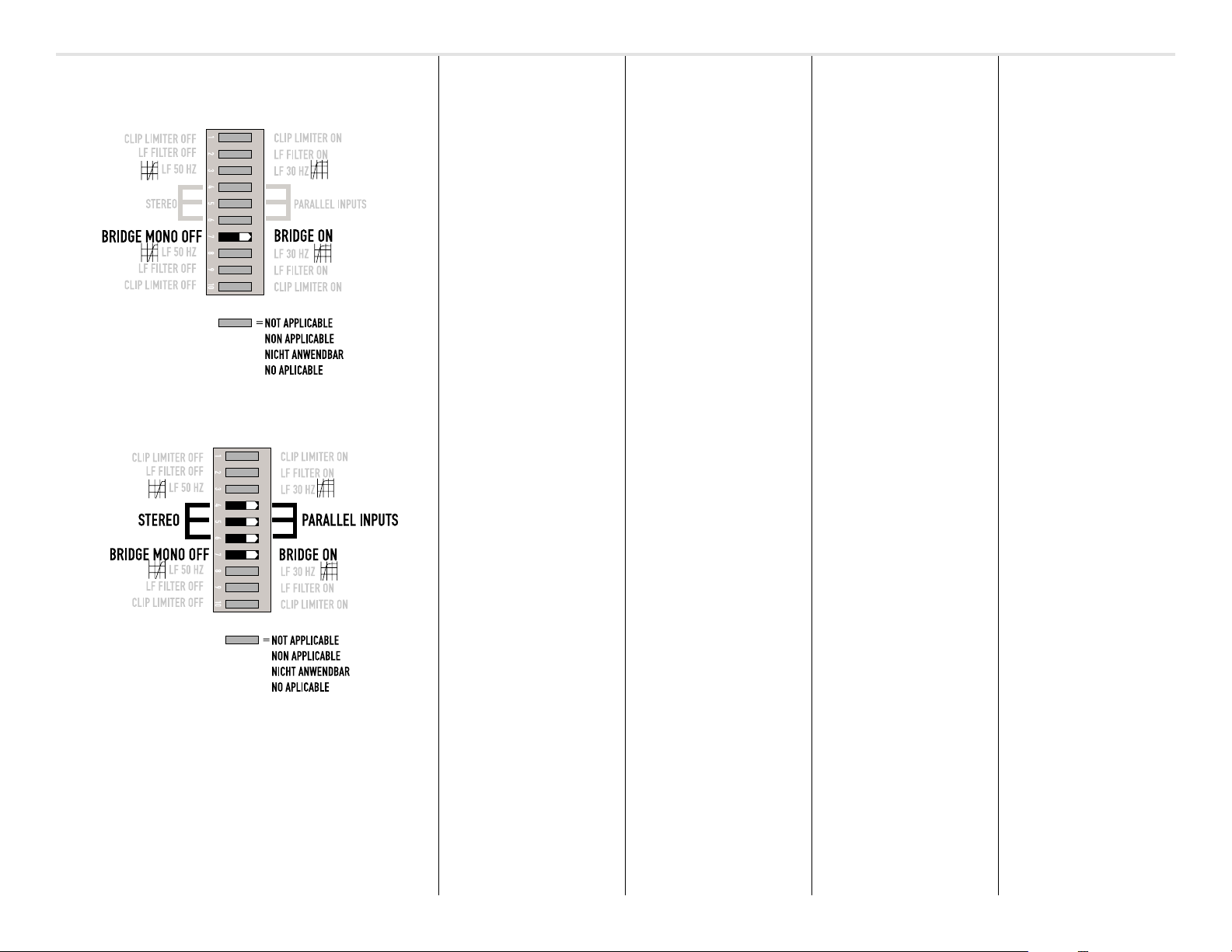
Bridge mono mode with configuration switch set for "Stereo"
Bridge mono mode with configuration switch set for "Parallel Inputs"
Minimum bridge mono load on PL2 amplifiers is 4 ohms.
L'impedance de charge minimum au modèle PL2 en le mode ponté
mono est 4 ohms.
Minimale Lastimpedanz bei Monobrückenbetrieb der PL2 ist 4 Ohm.
La impedancia de carga mínima del amplificador PL2 en el modo
puenteado en mono es 4 ohmios.
BRIDGE MONO MODE
This mode combines the full power
capabilities of both channels into a
single speaker system. The amplifier
internally re-configures so that the
drive signal is applied to both
channels with the correct phase
relationship. This delivers double the
output voltage, resulting in four
times the peak power and three
times the sustained power into a
single 8- or 4-ohm speaker load. The
Bridge Mono mode section on pages
12 and 13 describes the special
speaker connection used.
Examples:
• Driving a single 8-ohm speaker
with the combined 4-ohm power
of two channels.
• Driving a single 4-ohm speaker
with the combined 2-ohm power
of both channels.
Precautions:
• Bridge Mono mode makes it
possible to drive thousands of
watts into a single speaker. AC
current consumption will usually
be higher. Avoid excessive signal
level, and make sure the wiring
and speaker can handle the
power.
• If the load is less than 4 ohms, or
prolonged overloads occur, the
amplifier will probably mute for
several seconds during peaks.
• Do not use 2-ohm loads.
SEE THE ADDITIONAL BRIDGE
MONO MODE WARNINGS ON
PAGES 12 AND 13.
ET LEUR UTILISATION
MODE PONTÉ MONO
Ce mode combine la puissance des
deux canaux vers une seule sortie.
L'amplificateur est rebranché de
façon à ce que les deux canaux
fonctionnent en tant qu'unité. Ce
branchement double la tension de
sortie, ce qui multiplie par un facteur
de 4 la puissance en pointe et triple
la puissance en continu par rapport à
un canal simple dans un charge de 4
ou de 8 ohms. La section Mode
ponté mono en page 12-13 décrit les
branchements spéciaux des hautparleurs en ce mode.
Exemples:
• faire fonctionner un haut-parleur de
8 ohms avec la puissance combinée
à 4 ohms des deux canaux
• faire fonctionner un haut-parleur de
4 ohms avec la puissance combinée
à 2 ohms des deux canaux
Précautions:
• Le mode ponté mono permet
d'envoyer des milliers de watts de
puissance vers un seul haut-parleur.
La consommation de courant sera
plus élevée. S'assurer que le câblage
et le haut-parleur peuvent
supporter la puissance générée.
• Si la charge (haut-parleur) est de
moins de 4 ohms ou que des
surtensions prolongées se
produisent, il est possible que
l'amplificateur passe en mode
protection pour quelques
secondes lors de surtensions.
• Ne pas utiliser de charges de 2 ohms.
VOIR LES INSTRUCTIONS
ADDITIONNELLES POUR
UTILISATION EN MODE PONTÉ
MONO EN PAGE 12-13.
EINSTELLUNGEN
MONOBRÜCKENBETRIEB
Diese Betriebsart addiert die volle
Verstärkung beider Kanäle für eine
einzelnes Lautsprechersystem. Der
Verstärker wird intern so umkonfiguriert,
so daß beide Kanäle wie ein einzelner
Kanal funktionieren. Hierdurch steht
ungefähr die doppelte Ausgangsspannung, die vierfache Spitzenleistung
und ungefähr die dreifache Dauerleistung eines Einzelkanals in eine 8
oder 4 Ohm Last zur Verfügung.
Weitere Erläuterungen zur
besonderen Art des Anschlusses der
Lautsprecher finden Sie auf Seite 12
und 13.
Beispiele:
• Betrieb eines einzelnen 8 Ohm
Laut-sprecher mit der addierten 4
Ohm Leistung der zwei Kanäle
• Betrieb eines einzelnen 4 Ohm
Laut-sprecher mit der addierten 2
Ohm Leistung beider Kanäle
Vorsichtsmaßnahmen:
• Im Monobrückenbetrieb können
tausende Watt Leistung an einen
einzelnen Lautsprecher abgegeben
werden. Die Stromaufnahme des
Verstärkers wird höher als normal
sein. Vermeiden Sie daher über-
höhte Signalpegel und stellen Sie
sicher, daß die Verkabelung und
der Lautsprecher die hohe
Leistung verarbeiten können.
• Bei Lasten kleiner als 4 Ohm, oder
zu langen Übersteuerungen kann
der Verstärker für einige
Sekunden abschalten.
• 2 Ohm Lasten dürfen nicht
betrieben werden.
BITTE BEACHTEN SIE DIE
WARNHINWEISE AUF SEITE 12
UND 13.
Y AJUSTES
MODO PUENTEADO EN MONO
Este modo combina la capacidad
total de potencia de ambos canales,
en un solo sistema de bocinas. El
amplificador se reconfigura
internamente de manera que ambos
canales operen como uno. Esto
produce el doble de voltaje de salida,
cuatro veces la potencia en picos y
tres veces la potencia de sostenimiento en cargas de 8 y 4 ohmios. La
sección del modo "Puenteado en
Mono" en la página 12-13 describe
la conexión usada para las bocinas.
Ejemplos:
• Para alimentar una bocina de 8ohmios, con la potencia de dos
canales de 4-ohms.
• Para alimentar una bocina de 4ohmios, con la potencia de dos
canales de 2-ohms.
Precauciones:
• El modo de puenteado en mono
puede mandar miles de watts a
una sola bocina. El consumo de
corriente alterna (AC) también
será mayor. Evite niveles de
señales excesivos, y asegurese
que el cableado y las bocinas
resistan la potencia.
• Si la carga es menor a 4 ohms, ó
la saturación es muy frecuente, el
amplificador puede enmudecerse
(función Mute) durante los picos
por varios segundos.
• No use cargas de 2 ohmios.
LEA LAS PRECAUCIONES
ADICIONALES PARA EL MODO
DE PUENTEADO EN MONO EN
LA PÁGINA 12 y 13.
15
Page 16

PL2 dimensional information
INSTALLATION
Use four screws and washers when
mounting the amplifier to the front
rack rails. Support the amplifier while
securing to the rails to avoid
distorting the front ears.
Supporting the amp at the rear is
important, especially for mobile and
touring use. Rear rack mounting ear
kits are available from QSC’s
technical services department or by
special order from your dealer or
distributor.
INSTALLATION
Utiliser les quatre vis et rondelles de
montage pour fixer le devant de
l'amplificateur sur les rails de montage.
Il est recommandé de supporter
l'arrière de l'amplificateur, tout
particulièrement pour applications
mobiles et de tournée; des ensembles
de support sont disponibles du
service à la clientèle de QSC, ou en
commande spéciale chez votre
marchand ou distributeur local.
EINBAU
Benutzen Sie vier Befestigungsschrauben und Unterlegscheiben
zum Fronteinbau in das Rack.
Stützen Sie den Verstärker auch an
seiner Rückseite ab. Dies gilt besonders
für den mobilen Einsatz. Rückwärtige
Einbausätze können direkt bei QSC
oder den jeweiligen Händlern oder
Distributoren bestellt werden.
INSTALACIÓ N
Utilice cuatro tornillos con rondanas
cuando coloque el amplificador en la
parte frontal del rack.
De la misma manera apoye la parte
posterior, especialmente cuando
vaya a transportar el equipo. Las
asas de montaje están disponibles
en el departamento de servicios
técnicos de QSC o pídalas
directamente a su distribuidor.
PL2 rack mounting installation
and major dimensions
16
16
Page 17

Rear rack mounting ear kit installation-
INSTALLATION
The rear rack mouting ear kit may be
intsalled in two different ways.
Method 1: The amplifier is first
installed from the front of the rack
and then the ears are secured
directly to the amplifier with two
machine screws as shown, left. Then
the ears are secured to the rails
using ordinary rail hardware.
INSTALLATION EINBAU
INSTALACIÓ N
Method 1:
front & rear screws.
Method 2: The amplifier can be installed and removed easily
from the front without removing any rear hardware.
The amplifier can be removed only by removing
Method 2: The amplifier is first
installed from the front of the rack.
Then, the accessory rear ears are
positioned on the rear rack rails and
secured. The pin installation position
can now be selected. Install the pin
so that it fits well into the slot
provided on the amplifier's rear
mounting tab.
17
17
Page 18

or
ou
oder
ó
or
ou
oder
ó
CONNECTIONS
Inputs
Eingänge
CONEXIONESCONNEXIONS ANSCHLÜ SSE
EntradasEntrées
Use one of the three input connection options
shield
inverting
non-inverting
Each channel has active balanced
"Euro-style" terminal block, XLR and
¼-inch (6.3 mm) TRS jacks wired in
parallel. The input impedance is
12 kOhm balanced or 6 kOhm
unbalanced. Each channel's three
input jacks are wired in parallel.
Unused input jacks may be daisychained to additional amplifiers if
desired.
Balanced connection is
recommended. Balanced signals are
less prone to AC hum, but
unbalanced signals can be suitable
for short cable runs. The signal
source's output impedance should
be less than 600 Ohms to avoid high
frequency loss in long cables.
Chaque canal est muni de prises
XLR, ¼” (6.3 mm) et bloc détachable
“Euro-style” montés en parallèle,
avec branchement symétrique.
L’impédance d’entrée est de 12kOhm
en symétrique, et de 6kOhm en
branchement asymétrique.
Les signaux reçus en mode
symétrique sont moins sujets aux
ronflements dû aux interférences de
réseau électrique (hum), alors que les
branchements asymétriques peuvent
convenir pour les courtes distances.
L'impédance de sortie de la source
de signal devrait être de moins de
600 Ohm afin de réduire les pertes
en hautes fréquences avec de longs
câbles.
Jeder Kanal verfügt über electrisch
symmetrierte XLR Anschlüsse,
6,3 mm Stereo-Klinken und
Euroblock (Phönix) Anschlußstecker.
Die Eingangsim-pedanz beträgt
12 kOhm, symmetrisch und 6 kOhm
unsymmetrisch.
Symmetrische Signale verursachen
weniger Brummproblem, wobei
unsymmetrische Verbindungen
allerdings bei kurzen Kabelwegen
häufig ausreichen. Die
Quellimpedanz sollte dabei weniger
als 600 Ohm betragen, um einen
Höhenverlust bei längeren
Kabelwegen zu vermeiden.
Cada canal tiene una entrada activa
balanceada "Euro-style" tipo
terminal de bloque, XLR y TRS de 1/
4" (6.3mm) cableados en paralelo con
una impedancia de 12 kOhm
balanceada y 6 kOhm no
balanceada.
Las señales balanceadas son menos
propensas a inducir zumbidos debido
a la corriente alterna, pero para
cables cortos pueden usarse señales
no balanceadas. La impedancia de
salida debe ser menor de 600 ohms
para prevenir la pérdida de
frecuencias agudas en cables largos.
1/4-inch (6.3mm) TRS and XLR connection
•Balanced•Symétrique•Symmetrisch•Balanceado
shield
Terminal block balanced • bloc détachable
symêtrique • symetrische Anschlußstecker
• Entrada de bloque balanceado
18
Balanced inputs: Use the XLR, ¼-
inch (6.3 mm) TRS input jacks, or the
detachable terminal blocks.
Proper connection for all three
balanced input options are shown at
left.
Entrées symétriques: Utiliser la
prise XLR, ¼” (6.3 mm) ou le bloc
détachable “Euro-style.”
Symmetrische Eingänge: Verwenden Sie die XLR oder 6,3mm
Stereoklinkenbuchsen, oder die
Anschlußstecker.
Entradas balanceadas: Use las
entradas XLR o TRS de ¼ pulgada
(6.3 mm), o la terminal de bloque
modular.
Page 19

CONNECTIONS CONEXIONESCONNEXIONS ANSCHLÜ SSE
shield and
inverting
non-inverting
1/4-inch (6.3mm) phone plug connection
•Unbalanced•Asymétrique•Unsymmetrisch•No Balanceado
jumper
XLR unbalanced • XLR asymêtrique • unsymetrische XLR •
XLR no balanceado
jumper
Inputs (continued)
Unbalanced inputs: Connect the
unused side of the balanced input to
ground, as shown at left. A tip-sleeve
¼-inch (6.3 mm) connector will
correctly terminate the unused side
of the input without modification.
For two-channel (stereo) operation,
use the inputs for both Channel 1 and
Channel 2; for parallel or bridged
mono operation, use only the
Channel 1 input. See the section on
operating modes for more explanation.
To patch the audio signal to other
amps (parallel and bridged modes
only), see the instructions for using
parallel inputs on page 11.
TRS unbalanced • TRS
asymêtrique • unsymetrische Stereoklinke • TRS
no balanceado
Entrées (suite)
Entrées asymétriques:
Connectez le côté non-utilisé de
l'entrée symétrique au châssis, tel
qu'illustré ci-contre. Une fiche ¼" (6.3
mm) mono (Tip Sleeve) fermera le
circuit sans modification.
En utilisation deux canaux (stéréo),
utilisez les prises des canaux 1 et 2;
en mode parallèle ou ponté mono,
utilisez la prise du canal 1. Voir les
explications dans les sections
appropriées du présent manuel. Pour
relier le signal audio de cet
amplificateur vers d'autres
amplificateurs (mode parallèle et
ponté mono seulement), voyez les
instructions en page 11.
Eingänge (Fortsetzung)
Unsymmetrische Eingänge:
Verbinden Sie den ungenutzten Pin
des symmetrischen Steckers mit
Masse (siehe Abbildung). Bei einem
Mono-Klinkenstecker ist keine
Änderung nötig.
Im 2-Kanalbetrieb (Stereo), verwenden
Sie bitte beide Eingänge; im
Parallel-, bzw. Monobrückenbetrieb
verwenden Sie nur Eingang 1. Bitte
beachten sie die jeweiligen
Beschreibungen der ver-schiedenen
Betriebszustände. Um das Signal an
weitere Verstärker zu leiten (nur im
Parallel-, bzw. Monobrücken-
betrieb), beachten Sie bitte die
Beschreibungen auf Seite 11.
Entradas (continuado)
Entradas no balanceadas:
Conecte el lado libre de la salida
balanceada a tierra, como se muestra
a la izquierda. Con un conector tipo
tip-sleeve de ¼" (6.3mm) se llevará a
cabo la terminación apropiada del
conductor sin usar de la entrada sin
ninguna modificación.
Para operación en dos canales
(estéreo), use las entradas de los
canales 1 y 2. Para operación en
paralelo o puenteada en mono, use
la entrada del canal 1. Lea la sección
de los modos de operación para una
explicación más detallada. Para
enviar la señal de audio a otros
amplificadores (sólo en los modos
paralelo o puenteado en mono), lea
las instrucciones para entradas
paralelas en la página 11.
shield
jumper from
— to shield
Terminal block unbalanced •
bloc détachable asymêtrique •
unsymetrische Anschlußstecker
• Entrada de bloque no
balanceado
19
19
Page 20

2 channels/canaux/Kanäle/canales & 2 Speakons
(Stereo, bi-amp, or parallel mode; Modes stéreo, bi-amp ou parallèle; Stereo-, Bi-
amp- oder Parallelbetrieb; Modos estéreo, bi-amp o paralelo)
2 channels/canaux/Kanäle/canales & 1 Speakon
(Stereo, bi-amp, or parallel mode; Modes stéreo, bi-amp ou parallèle; Stereo-, Bi-
Amp- oder Parallelbetrieb; Modos estéreo, bi-amp o paralelo)
CONNECTIONS CONEXIONESCONNEXIONS ANSCHLÜ SSE
Outputs
The PL2 amplifier offers a choice of
output connections: two Neutrik
NL4MD Speakon jacks and "touchproof" binding post outputs.
Speakon™ Outputs
The Speakon connector is designed
specially for high-power speaker
connections. It locks in place,
prevents shock hazard, and assures
the correct polarity.
The upper Speakon jack has both
Channel 1 and Channel 2 outputs, so
it is especially useful for parallel, biamp, or bridged mono operation (see
bridged mono operating precautions
on page 13). The other Speakon
carries only Channel 2’s output. See
the illustrations at left.
For easier insertion, use the newerstyle NL4FC Speakon connectors
with quicklock thumb latches.
SPEAKER CABLING
Always use the largest wire size and
shortest length of wire practical for
any given inatallation. Larger wire
sizes and shorter lengths minimize
both loss of power and degradation
of damping factor.
speaker cables next to input
wiring.
Do not place
Sorties Speakon™
Les amplificateurs de série PL2 vous
offrent un choix de connexion de
sortie: deux prises Speakon et des
bornes à écrou.
Les prises Speakon sont conçues
spécifiquement pour la connexion de
haut-parleurs de haute puissance. Elles
verrouillent en place, préviennent les
risques de choc électrique, et assurent
le branchement avec polarité correcte.
La prise Speakon du haut porte les
signaux de sortie des deux canaux, elle
est donc très utile lors de branchement
en modes parallèle, bi-amplifié, ou
ponté mono (voir les instructions et
précautions à suivre pour le branchement
en mode ponté mono en page 13). La
prise du bas ne porte que le signal du
canal 2. Voir les illustrations ci-contre.
Pour insertion plus facile, utiliser la
nouvelle génération des Speakon
NL4FC avec loquet à ressort.
CÂBLAGE DU HAUT-PARLEUR
Les câbles de fort calibres et les courtes
distances minimisent à la fois les pertes
de puissance et la dégradation du
coefficient d'amortissement. Evitez
de placer les câbles de haut-parleurs
à proximité des câbles d'entrée.
Speakon™ Ausgänge
Die verstärker der PL2-Serie bieten
zwei verschiedene
Ausgangsanschlüsse: zwei Neutrik
NL4MD Speakonstecker und
anschlussklemmen.
Der Speakonanschluß wurde speziell
für den Anschluß von Hochleistungslautsprechern konzipiert. Er rastet
ein, verhindert elektrischen Schlag
und sorgt für die richtige Polarität.
Die obere Speakonbuchse enthält
beide Kanäle, so daß sie besonders für
Parallel-, Biamp- oder Monobrückenbetrieb geeignet ist (bitte beachten
Sie die Vorsichtsmaßnahmen wie
auf Seite 13 beschrieben). Die
andere Speakonbuchse enthält nur
die Signale von Kanal 2 (siehe auch
nebenstehende Zeichnung).
Für eine leichtere Anbindung,
verwenden Sie die NL4FC-Speakonstecker der neueren Generation.
LAUTSPRECHERKABEL
Dickere und kürzere Kabel verringern
sowohl Leistungsverlust wie eine Verschlechterung des Dämpfungsfaktors.
Verlegen Sie keine Ausgangskabel
neben den Eingangskabeln.
Salidas Speakon™
Los amplificadores PL2 ofrecen
diferentes opciones para conexiones
de salida: dos conectores Speakon
NL4MD de Neutrik y por medio de
las terminales con tornillo.
El conector Speakon está diseñado
especialmente para conexiones de
bocinas de alta potencia. Se ajusta
fijamente, previene cortos eléctricos
y asegura una correcta polaridad.
El conector Speakon superior tiene
las salidas de los canales 1 y 2, y se
usa para una operación en paralelo,
biamplificada, o puenteada en mono
(lea las recomendaciones de la
página 13). El otro conector Speakon
sólo tiene la salida del canal 2.
Observe las ilustraciones a la
izquierda.
Para facilitar la inserción de los
conectores, le recomendamos que
use los nuevos conectores Speakon
NL4FC con retén.
CABLEADO DE BOCINAS
Los cables gruesos y los trayectos cortos
minimizan la pérdida de potencia y
degradación por el factor de amortiguación. No coloque los cables de las
bocinas cercanos a los de entrada.
Bridged mono • Mono ponté • Monobrückenbetrieb • Mono puente
20
WARNING: To prevent electric
shock, do not operate the amplifier with any of the conductor
portion of the speaker wire exposed.
AVERTISSEMENT: Afin de
prévenir les risques de choc
électrique, ne pas utiliser
l'amplificateur si une portion de
conducteur du fil de hautparleur est exposée.
WARNUNG: Um elektrische
Schläge zu vermeiden, sollte der
Verstärker nicht betrieben
werden, wenn blanke Kabelenden sichtbar sind.
¡AVISO! Para evitar una
descarga eléctrica, no opere el
amplificador si alguno de los
cables de la bocina está
expuesto.
Page 21

CONNECTIONS
Binding post outputs
Three methods may be used to
connect to the binding post output
terminals:
• Stripped wire inserted from the side
and passed through the hole in the
binding post shaft; then the barrel
is tightened.
• Spade terminal (1/4-inch stud size)
inserted from the side and then
secured by tightening the barrel.
• Banana plug (single or dual)
inserted directly into the post ends.
Tighten down the barrel to allow
full insertion of the banana plug.
Banana plug capability is
provided on
models ONLY!
non-European
Bornes à écrou
CONEXIONESCONNEXIONS ANSCHLÜ SSE
Anschlussklemmen Terminales con tornillo
WARNING: To prevent electric
shock, do not operate the amplifier with any of the conductor portion of the speaker wire
exposed.
Connections for stereo and parallel
operations.
Connections for bridged mono
operation. See bridged mono
operating precautions on page 13.
SPEAKER CABLING
Always use the largest wire size and
shortest length of wire practical for
any given installation. Larger wire
sizes and shorter lengths minimize
both loss of power and degradation
of damping factor.
speaker cables next to input
wiring.
Do not place
AVERTISSEMENT: Afin de
prévenir les risques de choc
électrique, ne pas utiliser
l'amplificateur si une portion de
conducteur du fil de hautparleur est exposée.
Connexions pour utilisation en
modes stéréo ou parallèle.
Connexions pour utilisation en mode
ponté mono. Voir les instructions et
précautions à suivre pour le branchement en mode ponté mono en page 13.
CÂBLAGE DU HAUT-PARLEUR
Les câbles de fort calibres et les
courtes distances minimisent à la fois
les pertes de puissance et la
dégradation du coefficient
d'amortissement. Evitez de placer les
câbles de haut-parleurs à proximité
des câbles d'entrée.
WARNUNG: Um elektrische
Schläge zu vermeiden, sollte
der Verstärker nicht betrieben
werden, wenn blanke Kabelenden sichtbar sind.
Anschlüsse für Stereo-, bzw.
Parallelbetrieb.
Anschluß im Monobrückenbetrieb.
Bitte beachten Sie die
Erläuterungen auf Seite 13.
LAUTSPRECHERKABEL
Dickere und kürzere Kabel verringern
sowohl Leistungsverlust wie eine Verschlechterung des Dämpfungsfaktors.
Verlegen Sie keine Ausgangskabel
neben den Eingangskabeln.
¡AVISO! Para evitar una
descarga eléctrica, no opere el
amplificador si alguno de los
cables de la bocina está
expuesto.
Conexiones para operación en
estéreo o paralelo.
Conexiones para operación
puenteada en mono. Lea las
recomendaciones de la página 13.
CABLEADO DE BOCINAS
Los cables gruesos y los trayectos cortos
minimizan la pérdida de potencia y
degradación por el factor de amortiguación. No coloque los cables de las
bocinas cercanos a los de entrada.
21
21
Page 22

CONNECTIONS CONEXIONESCONNEXIONS ANSCHLÜ SSE
Examples of Accessories for PL2 Amplifiers
2-way system
3-way system
Subwoofer
Operating voltage
(AC mains)
The correct AC line voltage is shown
on the serial number label (page 8,
item #11). Connecting to the wrong
line voltage is dangerous and may
damage the amplifier. The power
cord attaches to the IEC connector
on the rear panel (page 8, item #12).
Use the cord supplied with the
amplifier, or an equivalent. Insure
that the wire gauge of the cord is
#14 AWG. Use of smaller wire
gauges can reduce the line voltage
available to the amplifier. A power
cord retaining clip (page 8, item
#12a) is provided with the amplifier.
We recommend you install and use
the retaining clip to prevent
accidental power cord disconnection.
DATAPORT
The amplifier features a DataPort
(page 8, item #1) which connects to
accessory products to enhance your
amplifier application. The CM16a
Amplifier Network Monitor can
remotely control and monitor your
PL2 amplifier. Other QSC accessories
connect via the HD-15 DataPort
connector.
ACCESSORIES
Accessories for the PL2 amplifiers
include crossover, filter and DSP
modules that mount directly to the
rear panel of the amplifier.
These accessories include the XC-3,
a 2-way crossover; the SF-3
Subwoofer Filter; and the LF-3 LowFrequency filter. You can use these
accessories to create 2-way, 3-way,
and 4-way (3-way plus subwoofer)
active systems.
For accessory information, contact
QSC's Technical Services
Department or your QSC
representative.
Tension d'utilisation
(alimentation CA)
Port de données
ACCESSOIRES
Netzanschluß Voltaje de operación
(alimentación CA)
DataPort
ZUBEHÖR
DataPort (puerto de datos)
ACCESORIOS
22
Page 23

OPERATION
UTILISATION BETRIEBOPERACIÓ N
Power Switch Operation
Gain Control
Ch.1
Front Panel (right side)- LED indicators and Gain controls
LED indicators
-ledoM 812LP 422LP 032LP 632LP
mumixaM
BdniniaG
Bd23Bd43Bd53Bd63
Maximum Gain (in dB) by Model Number
Gain Control
Ch. 2
AC power switch
Before applying power, check all
connections and turn down the gain
controls. The "soft start" sequence
starts with the
LED at half brightness. A few
seconds later the fan starts, the
POWER
and the amplifier mutes for two
seconds. The
bright red. When the CLIP LEDs go
out, the amplifier is ready for
operation.
POWER
indicator
indicator fully illuminates
CLIP
LEDs will glow
LED indicators
At full brightness, the green
POWER
LED indicates that the
amplifier is operating. Half
brightness means the amp is in its
startup sequence or that the
amplifier is in
As the input signal strength
increases, the green
-20dB,
indicators light respectively at 0.1%,
1% and 10% of full power.
The red
during overload (clipping). A bright,
steady glow indicates protective
muting. If this occurs during use, see
Troubleshooting.
The yellow
when the amp is in bridged mono
mode.
The orange
illuminates when the amp is in
Parallel Input mode.
STANDBY
and amber
CLIP
-10dB
LED indicator flashes
BRIDGE
PARALLEL
mode.
SIGNAL,
LED
LED illuminates
LED
Gain controls
The gain controls are detented (21
steps) for repeatable adjustment.
Surrounding the gain control knob,
the attenuation level is shown in dB.
Maximum gain differs by model and is
given in the table at the left.
Interrupteur
d'alimentation CA
Avant de mettre l'amplificateur en
marche, vérifiez toutes les connexions
et fermez les contrôles de gain. A la
mise en marche, la fonction "Soft
start" est activée, avec comme indication
l'allumage de la DEL
intensité. Quelques secondes plus tard
le ventilateur démarre et l'amplificateur
passe en mode protection pour une
seconde, tel qu'indiqué par la DEL
qui passe au rouge. La DEL
passe alors à pleine intensité et
l'amplificateur est prêt à fonctionner.
POWER
à demi-
CLIP
POWER
Indicateurs DEL
Au fur et à mesure que le niveau de
signal augmente, les DEL vertes
SIGNAL, -20dB
respectivement à 0.1%, 1%, et 10% de
la pleine puissance de l'amplificateur.
La DEL
(écrêtement). La DEL reste allumée à
pleine intensité pour indiquer la mise
en sourdine par le circuit de
protection. Si cette condition se
présentait lors de l'utilisation, voir la
section dépannage de ce manuel.
La DEL jaune
l'amplificateur a été réglé en mode
ponté mono.
La DEL jaune
que l'amplificateur a été réglé en
mode parallèle.
, et
-10dB
CLIP
clignote lors de surcharges
BRIDGE
PARALLEL
allument
indique que
indique
Contrôles de gain
Les contrôles de gain à taquets
permet les réajustements répétés. Le
gain en tension de l'amplification est
indiqué en dB.
Netzschalter
Bevor Sie einschalten, überprüfen
Sie alle Verbindungen und drehen
Sie die Verstärkung zurück. Die
Softstart-Sequenz beginnt mit
halber Helligkeit der
Einige Sekunden später beginnt der
Ventilator zu laufen und der
Verstärker schaltet für etwa eine
Sekunde stumm, wobei die rote
CLIP
LED hell aufleuchtet. Danach
erscheint die
voller Helligkeit und der Verstärker
ist betriebsbereit.
POWER
POWER
-Anzeige in
LED.
LED-Anzeige
Bei steigendem Eingangssignal,
leuchten die grünen
und
-10dB
und zeigen 0,1%, 1% und 10% der
möglichen vollen Leistung an.
Die rote
CLIP
Übersteuerungen (Clipping) auf. Ein
helles, gleichmäßiges Leuchten zeigt
außerdem schützendes Stummschalten
an. Falls dieser Zustand während des
Betriebs auftritt, lesen Sie bitte den
Abschnitt Fehlerbehebung.
Die gelbe
wenn der Verstärker Monobrücke
betrieben wird.
Die gelbe
daß die Parallel Input Schalter
eingestellt wurden.
SIGNAL, -20dB
LEDs nacheinander auf
LED leuchtet während
BRIDGE
LED leuchtet auf,
PARALLEL
LED zeigt an,
Verstärkungsregler
Die Regler wurden als Rastpotentiometer ausgelegt, um reproduzierbare
Einstellungen zu erlauben. Die
tatsächliche Verstärkung wird in dB
angezeigt.
Interruptor de encendio
Antes de encender el equipo, revise
las conexiones y baje los controles
de ganancia. La secuencia de
encendido "suave" inicia con el
indicador LED
Un par de segundos después el
ventilador se enciende y el
amplificador hace un silencio
momentáneo de protección, que se
puede visualizar en los indicadores
LED rojos de
indicador
completamente y el amplificador
está listo para operar.
POWER
CLIP
POWER
a media luz.
. Después el
se enciende
Indicadores LED
A medida de que la señal aumenta,
los indicadores verdes de
los de
-20 dB
respectivamente al 0.1%, 1%, y 10%
de la potencia máxima.
El indicador LED rojo de
parpadea cuando hay saturación
(clips). Cuando permanece
encendido indica "enmudecimiento"
(función Mute) de protección. Si
ocurre durante el uso, lea la sección
Solución de Problemas.
El LED amarillo de
que el amplificador está en modo
puenteado en mono.
El LED amarillo de
que los interruptores de entrada
paralela se han activado.
y
-10 dB
BRIDGE
PARALLEL
SIGNAL
, se iluminan
CLIP
,
indica
indica
Controles de ganancia
Los controles de ganancia han sido
diseñados para un ajuste continuo.
El voltaje de ganancia del amplificador
aparece en decibeles.
,
23
23
Page 24

Security Panel Installation: Step 1
Security Panel Installation: Step 2
OPERATION
Security panel
After setting the gain controls, you
can install the security panel to
prevent tampering and accidental
misadjustment. After the knobs have
been removed and the gain setting
checked, install the security panel as
shown in the general illustration to
the left and on next page.
INSTALLING THE SECURITY
PANEL
NOTE! The numbered steps (below)
refer to the numbered
illustrations on this and the
following page.
1. Remove the gain control knobs by
firmly grasping each knob with
your fingers and firmly pulling
straight out. Do not pry on the
knob, as damage to the gain
control could result.
2. Use a 9/64" or 3.5 mm hex key to
back the screw out several turns.
3. Slide the right end of the security
panel just under the screw head.
4. There are tabs on the left end of
the security panel. Insert them
into the keyed portion of the
rightmost ventilation slots, then
slide the panel to the right so it
locks in the slot.
5. Now insert the tabs on the right
end of the security panel into the
pair of slots at that end, then
tighten the screw to secure the
panel. Do not overtighten.
UTILISATION BETRIEBOPERACIÓ N
Plaquette de sécurité
Après avoir ajusté les contrôles de
gain, vous pouvez installer la
plaquette de sécurité afin de
prévenir l’altération ou les mauvais
ajustements accidentels.
INSTALLATION DE LA
PLAQUETTE DE SÉCURITÉ
1.
2. Utiliser une clé hexagonale de 9/64"
3. Glisser l’extrémité droite de la
4. Passer les griffes de l’autre
5. Pousser les chevilles de l’extrémité
ou 3.5 mm pour desserrer la vis
plaquette sous la vis
extrémité de la plaquette par la
dernière bouche de ventilation,
puis glisser vers la droite jusqu’à
ce que la plaquette s’aligne dans
les ouvertures prévues à cet effet.
droite de la plaquette dans les
ouvertures prévues à cet effet,
puis resserrer la vis. Prendre soin
de ne pas trop serrer.
Sicherheitsabdeckung
Nachdem die Verstärkung eingestellt
wurde, kann das Abdeckblech installiert
werden, um eine Fehlbedienung
auszuschließen oder unabsichtliches
Verstellen zu verhindern.
INSTALLATION DER
SICHERHEITSABDECKUNG
1.
2. Verwenden Sie einen 3,5 mm
Innensechskantschlüssel um die
Schraube zu lockern
3. Schieben Sie die rechte Seite der Abdeckung unter den Schraubenkopf
4. Auf der linken Seite des Abdeckungsbleches befinden sich kleine
Halterungen. Schieben Sie diese
in den vorgesehenen Teil auf der
rechten Seite des Lüftungsgitters.
Schieben Sie die Abdeckung dann
nach rechts, so daß es sich in der
Öffnung verkeilt
5. Schieben Sie gleichzeitig die
Halterungen in die dafür
vorgesehenen Öffnungen auf der
rechten Seite und ziehen Sie die
Schrauben fest.
Panel de seguridad
Después de haber ajustado los controles de ganancia, puede instalar el
panel de seguridad para prevenir
que estos sean reajustados o que los
ajustes sean cambiados por accidente.
INSTALACIÓN DEL PANEL DE
SEGURIDAD
1.
2. Use una llave Allen (hex) de 9/64"
ó 3.5 mm para girar el tornillo
varias vueltas.
3. Resbale la parte derecha del
panel de seguridad un poco abajo
de la cabeza del tornillo.
4. En la parte izquierda del panel de
seguridad encontrará lengüetas.
Insértelas en el espacio indicado en
las ranuras del ventilador, después
mueva el panel hacia la derecha
hasta que quede asegurado con
la ranura.
5. Ahora inserte las lengüetas en el
par de ranuras al final de la parte
derecha del panel, y después apriete
el tornillo para asegurarlo. No lo
apriete excesivamente.
24
Page 25

Security Panel Installation: Step 3
OPERATION
Security Panel
UTILISATION
Plaquette de sécurité
BETRIEB
Sicherheitsabdeckung
OPERACIÓ N
Panel de seguridad
Security Panel Installation: Step 4
REMOVING THE SECURITY
PANEL
1. Use an angle 9/64" or 3.5 mm hex
key to back the screw out several
turns.
2. Use a small flat screwdriver to lift
the right end of the security panel
so that its tabs are free of the
slots in the front panel.
3. Slide the security panel to the left
until you can lift the left end free
of the slots, then slide the panel
to the left to remove it from
behind the screw.
4. Re-install the gain control knobs
by aligning the flat spot on the
shaft with the flat on the knob,
and then pushing the knob firmly
onto the shaft.
POUR ENLEVER LA PLAQUETTE
DE SÉCURITÉ
1. Utiliser une clé hexagonale de 9/64"
ou 3.5 mm pour desserrer la vis
sur plusieurs tours.
2. Utiliser un petit tournevis pour lever
l’extrémité droite de la plaquette,
afin de dégager les chevilles.
3. Glisser la plaquette vers la gauche
pour dégager les griffes, puis
retirer la plaquette.
4.
Security Panel Installation: Step 5
AUSBAU DER
SICHERHEITSABDECKUNG
1. Verwenden Sie den 3,5 mm
abgewinkelten Innensechskant,
um die Schraube zu lockern.
2. Heben Sie die rechte Seite der
Abdeckung mit einem kleinen,
flachen Schraubenzieher heraus.
3. Schieben Sie die Abdeckung
unter der Schraube so weit nach
links, daß sie problemlos entfernt
werden kann.
4.
PARA QUITAR EL PANEL DE
SEGURIDAD
1. Use una llave Allen (hex) de 9/64"
ó 3.5 mm para girar el tornillo
varias vueltas.
2. Use un destornillador pequeño
para levantar la parte derecha del
panel de manera que las
lengüetas sean liberadas de las
ranuras en el panel frontal.
3. Mueva el panel de seguridad
hacia la izquierda hasta que lo
pueda sacar de las ranuras,
después resbalelo hacia la
izquierda para sacarlo detrás del
tornillo.
4.
25
Page 26

OPERATION
UTILISATION BETRIEBOPERACIÓ N
Rear-to-Front Air Flow of QSC Amplifiers
Fan cooling
The fan varies speed automatically
to maintain safe internal
temperatures and minimize noise.
Keep the front and rear vents clear
to allow full air flow.
Hot air exhausts out the front of the
amp so it does not heat the interior
of the rack. Make sure that plenty of
cool air can enter the rack, especially
if there are other units which
exhaust hot air into it.
Safe operating levels
The amp's protective muting system
guards against excessive internal
temperatures. With normal
ventilation and 4- to 8-ohm loads,
the amplifier will handle any signal
level including overdrive—but make
sure that the speakers can handle
the full power! However, lower load
impedances and higher signal levels
produce more internal heating. Into
2-ohm loads, frequent or prolonged
clipping (indicated by constant
flashing of the red
trigger power cutback or even
protective muting.
Bridged mono
output impedance of the amp;
4 ohms is the minimum load
impedance. Heavy clipping may
cause muting. If this happens, see
Troubleshooting section.
CLIP
LED) may
mode doubles the
Ventilation
La vitesse de rotation du ventilateur
est proportionnelle à la température
du radiateur, afin de maintenir la
température interne à un niveau
acceptable et de réduire le bruit.
S’assurer de ne pas bloquer les
entrées ou sorties d’air de
l’amplificateur.
L'air chaud sort par le devant de
l'amplificateur afin de pas surchauffer
l'intérieur du coffret d'équipement.
Assurez vous que beaucoup d'air
frais puisse entrer dans le coffret,
tout particulièrement si vous utilisez
d'autres appareils qui soufflent leur
air chaud à l'intérieur du coffret.
Niveaux d'utilisation
sécuritaire
Le circuit de protection de l'amplificateur
entre en fonction et met le signal en
sourdine lors de température excessive.
Avec une charge de 4 ou de 8 ohms et
avec une ventilation normale, l'amplificateur fonctionnera sans arrêt avec
tout signal, incluant les surcharges—
assurez vous cependant que les hautparleurs peuvent accepter toute la puissance de l'amplificateur. Il est possible
que des charges d'impédance plus faible
ou que des niveaux de signal plus élevés
génèrent plus de chaleur. Ainsi, une
charge de 2 ohms accompagnée de
surcharges constantes, tel qu'indiqué
par l'allumage continuel de la DEL
CLIP
, pourrait amener l'amplificateur
à réduire le niveau de puissance,
voire à amener le passage en mode
protection, avec mise en sourdine.
Le mode ponté mono double l'impédance
de sortie de l'amplificateur; 4 Ohm
devient donc la charge minimum.
L'écrêtage continuel pourrait entraîner
la mise en sourdine. Si cette condition
se présentait lors de l'utilisation, voir la
section dépannage de ce manuel.
Lüfterkühlung
Die Lüftergeschwindigkeit ist geregelt,
um immer einen sicheren Betrieb zu
gewährleisten und Störgeräusche zu
vermindern. Stellen Sie sicher, daß die
Lufteintritts- und -austrittsöffnungen
nicht verlegt sind.
Die heiße Abluft tritt aus der Front
des Verstärkers aus, damit das Rack
nicht aufgeheizt wird. Stellen Sie
sicher, daß ausreichend kühle Luft in
das Rack gelangen kann. Dies gilt
besonders dann, wenn andere Geräte
warme Kühlluft in das Rack leiten.
Betriebspegel
Die Schutzabschaltung des Verstärkers
schützt vor übermäßigen internen
Temperaturen. Bei normaler Lüftung und
Lasten von 4–8 Ohm kann der
Verstärker jedes Signal,
einschließlich Über-steuerungen
problemlos verarbeiten—stellen Sie
aber sicher, daß die
angeschlossenen Lautsprecher die
Leistung verarbeiten können.
Niedrigere Impedanzen und höhere
Signalpegel führen zu größerer Abwärme. Häufige oder lange Übersteuer-
ungen (erkennbar durch dauerndes
Aufflackern der roten
Lasten von 2 Ohm können eine
Leistungs-verringerung oder sogar
eine Abschalt-ung der Endstufe zur
Folge haben.
Der Monobrückenbetrieb verdoppelt die
Ausgangsimpedanz des Verstärkers.
Daher dürfen in dieser Betriebsart
keine Lasten kleiner 4 Ohm
angeschlossen werden. Erhebliche
Übersteuerungen können ein
Abschalten zur Folge haben. In
diesem Fall lesen Sie bitte den
Abschnitt Fehlerbehebung.
CLIP
LED) mit
Ventilación
Para minimizar el ruido, el ventilador
varía su velocidad automáticamente
haciendo que se mantengan
temperaturas operativas internas
seguras. Mantenga las ranuras de
respiración libres para permitir que
el aire fluya libremente.
El aire caliente sale por la parte frontal
del amplificador para no calentar el
rack. Asegúrese de que circule aire
fresco en el rack, especialmente si
hay otras unidades que generan aire
caliente hacio adentro.
Niveles adecuados de
operación
El sistema de "enmudecimiento"
(función
Mute
con temperaturas altas internas. Con
una ventilación normal y cargas de 4 y
8 ohmios, el amplificador puede manejar
cualquier nivel de señal incluyendo la
saturación—pero verifique que sus
bocinas puedan manejar esa potencia.
Sin embargo, las bajas impedancias y
los altos niveles de señal producen calor
interno. En cargas de 2 ohmios, con
'clipeo'
cado por el parpadeo del LED
puede ocurrir un corte de corriente o
un "enmudecimiento" de protección.
El modo puenteado en mono duplica la
impedancia de salida del amplificador;
4 ohmios es la mínima impedancia de
carga. La saturación extrema puede
causar paro total. Si ocurriese ésto
lea la sección Solución de
Problemas.
) de protección, se activa
frecuente o prolongado (indi-
CLIP
)
26
26
Page 27

SOUND REINFORCEMENT
APPLICATIONS APPLICATIONS ANWENDUNGS-
APLICACIONES
BEISPIELE
Mono Mix
Stereo Mix
Biamp Monitor
27
Page 28

SOUND REINFORCEMENT
APPLICATIONS APPLICATIONS ANWENDUNGS-
APLICACIONES
BEISPIELE
Stereo biamp mix #1, + subwoofer
Stereo biamp mix #1
Stereo biamp mix #2
28
Page 29

1 Cabinet
APPLICATIONS
INSTRUMENT AMPLIFICTAION
APPLICATIONS APLICACIONES
ANWENDUNGSBEISPIELE
Biamp
2 Cabinet
29
29
Page 30

TROUBLESHOOTING
D É PANNAGE FEHLERBEHEBUNG
SOLUCIÓN DE PROBLEMAS
Problem:
• Indication:
no sound
POWER
indicator not lit
• Check the AC plug.
• Confirm that the AC outlet works
by plugging in another device. If
too many amplifiers are used on
one outlet, the building's circuit
breaker may trip and shut off power.
• An overload in
may cause the amplifier to click
off for three seconds, indicated by
the half-bright
followed by a normal restart cycle.
Check the load impedance (4 ohms
minimum), or reduce signal level.
• An amplifier which keeps shutting
off may have a serious internal
fault. Turn it off, remove AC
power, and have the amplifier
serviced by a qualified technician.
•
INDICATION:
NOT LIT
• If the green
LED is at full brightness, yet the
signal LEDs indicate no signal,
check the input. Make sure the
signal source is operating and try
another input cable. Connect the
source to another channel or
amplifier to confirm its operation.
bridged mono
POWER
SIGNAL LED
POWER
mode
LED,
indicator
Problème:
•
Indication:
pas de son
DEL
"POWER" éteinte
• Vérifiez le branchement du
cordon d'alimentation.
• Assurez vous que la prise de courant
fonctionne en y branchant un autre
appareil. Un trop grand nombre
d'amplificateurs reliés au même
circuit pourraient faire déclencher le
disjoncteur, coupant l'alimentation.
• Une surcharge en mode ponté mono
pourrait éteindre momentanément
l'amplificateur, tel qu'indiqué par
la DEL
POWER
qui passera à demiintensité, suivi par le cycle normal
d'allumage. Vérifiez l'impédance de
la charge (4 ohms minimum), ou
réduisez le niveau de signal.
L'allumage continu des DEL
indique la mise en sourdine par le
circuit de protection à cause de
surchauffe.
• Un amplificateur qui passe
continuellement en mode protection
pourrait être défectueux. Eteignez
l'amplificateur, débranchez le,
puis faites le vérifier par un
technicien compétent.
•
INDICATION:
ÉTEINTS
• Si la DEL
mais que les DEL
éteintes, vérifiez la source de
signal. Assurez vous que la source
fonctionne normalement, puis
essayez d'autres câbles de raccord.
Brancher le signal de source à un
autre canal d'amplificateur pour
confirmer la présence de signal.
DEL SIGNAL
POWER
est allumée,
SIGNAL
CLIP
restent
Problem:
•
ANZEICHEN:
kein Ton
POWER
Anzeige leuchtet nicht
•Überprüfen Sie den Netzstecker.
• Stellen Sie sicher, daß die Steck-
dose Strom führt, indem Sie ein
anderes Gerät einstecken. Falls zu
viele Verstärker angeschlossen sind,
kann die Haussicherung ansprechen
und die Versorgung unterbrechen.
• Eine Übersteuerung im Monobrückenbetrieb kann den Verstärker
für drei Sekunden stummschalten,
was durch eine halbhelle
LED angezeigt wird. Überprüfen Sie
die Impedanz der angeschlossenen
Lautsprecher (minimal 4 Ohm!),
oder reduzieren Sie den
Signalpegel. Eine hell
aufleuchtende, rote
zeigen eine thermische
Abschaltung an.
• Ein Verstärker der ausgeschaltet
bleibt, kann einen internen Defekt
haben. Schalten Sie ihn aus,
trennen Sie ihn von der
Netzversorgung und lassen Sie
den Verstärker von qualifiziertem
Servicepersonal überprüfen.
•
ANZEICHEN:
ANZEIGEN LEUCHTEN NICHT
• Wenn die grüne
voller Helligkeit leuchtet, die Signal
LEDs aber kein Signal anzeigen,
überprüfen Sie den Eingang.
Stellen Sie sicher, daß die Quelle
arbeitet und versuchen Sie es mit
einem anderen Eingangskabel.
Schließen Sie die Quelle an einen
anderen Verstärker an, um
sicherzustellen, daß sie arbeitet.
CLIP
SIGNAL
POWER
POWER
LED
LED in
Problema:
• Indicación:
no hay sonido
El indicador de
encendido no se ilumina
• Revise el cable de corriente.
• Confirme que la toma de corriente
funcione conectando otro aparato. Si
se conectan muchos amplificadores
a una sola toma, el circuito se
sobrecarga y se desconecta.
• Una sobrecarga en el modo de
puenteado en mono puede causar
un apagado momentáneo, como de
tres segundos, y el indicador LED
de
POWER
bajará la intensidad de
su luz, reiniciando la secuencia de
encendido. Verifique la impedancia
de carga (4 ohmios mínimo), o
reduzca el nivel de la señal. Si el
LED rojo de
indicará un apagado térmico.
• Un amplificador que se apagada
continuamente, puede tener una
falla interna. Apáguelo,
desconéctelo de la toma de
corriente y llévelo con un técnico
especializado para su revisión.
•
INDICACIÓN:
LED DE SEÑAL NO SE ILUMINA
• Si el indicador verde de
está completamente iluminado,
pero el LED de signal no indica
nada, revise las entradas.
Asegúrese de que exista la señal
y cambie los cables en las
entradas. Conecte la señal a otro
canal u otro amplificador para
confirmar su funcionamiento.
CLIP
se ilumina
EL INDICADOR
POWER
30
30
Page 31

TROUBLESHOOTING
D É PANNAGE FEHLERBEHEBUNG
SOLUCIÓN DE PROBLEMAS
No sound (continued)
•
INDICATION:
RESPONDING TO SIGNAL
LEVEL
• If the green SIGNAL, -20 dB,
and -10 dB indicators are lighting
normally, the fault is somewhere
between the amp and the speaker.
Check the speaker wiring for breaks.
Try another speaker and cable.
•
INDICATION:
BRIGHT AND STEADY
The amplifier is in protective muting.
• One second of muting is normal
when the amp is turned on or off.
• Overheating will cause protective
muting. The fan will be running at
full speed and the chassis will be
hot to the touch; sound should
resume within a minute as the
amplifier cools to a safe operating
temperature. Check for proper
ventilation. If the fan isn't running
at all, the amplifier requires
servicing.
SIGNAL LEDs
CLIP LEDs
Pas de son (suite)
•
INDICATION:
FONCTIONNENT
NORMALEMENT
• Si les DEL
-10dB
le problème se situe entre la sortie
de l'amplificateur et le haut-parleur.
Vérifiez l'intégrité du câble de
haut-parleur. Essayez un autre
câble et un autre haut-parleur.
•
INDICATION:
ALLUMÉES EN CONTINU
L'amplificateur est en mode
protection.
• La mise en sourdine pour une
seconde est normale lors de la
mise en tension et hors-tension
de l'amplificateur.
• La surchauffe de l'amplificateur
entraîne la mise en sourdine de
l'amplificateur. Le ventilateur
tournera alors à pleine vitesse et le
châssis sera chaud au contact; le son
devrait revenir sitôt l'amplificateur
refroidi à température normale
d'utilisation. Assurez une ventilation
suffisante. Si le ventilateur ne
tournait pas, l'amplificateur
serait défectueux.
DEL DE SIGNAL
SIGNAL, -20dB
fonctionnent normalement,
DEL CLIP
et
Kein Ton (Fortsetzung)
•
ANZEICHEN:
ZEIGEN LEUCHTEN NORMAL
• Wenn die grüne
und
-10dB
liegt der Fehler an anderer Stelle
zwischen Verstärker und Lautsprecher. Überprüfen Sie die Lautsprecherleitungen auf Unterbrechungen. Schließen Sie einen anderen
Lautsprecher mit anderen Kabeln an.
•
ANZEICHEN:
LEUCHTET HELL UND
GLEICHMÄßIG
Die Schutzschaltung hat den
Verstärker abgeschaltet.
• Eine Abschaltung von einer
Sekunde Dauer ist beim Ein- oder
Ausschalten normal.
•Überhitzung führt zur Sicherheits-
abschaltung. Dabei läuft der Lüfter
in der höchsten Stufe, wobei sich das
Gehäuse sehr heiß anfühlt. Der Ton
sollte nach einer Minute wieder zur
Verfügung stehen, nachdem die
Endstufe wieder Betreibstemperatur
erreicht hat. Soregen Sie für eine
freie Luftzufuhr. Falls der Lüfter
nicht hochläuft, liegt ein Defekt
vor. Wenden Sie sich bitte an Ihre
nächste Servicestation.
SIGNAL AN-
SIGNAL, -20dB
LEDs normal aufleuchten,
CLIP ANZEIGE
No hay sonido (continuación)
•
INDICACIÓN:
LED DE "SIGNAL" Y LOS INDICADORES DE NIVELES SE
ENCIENDAN AL DETECTAR
EL NIVEL DE LA SEÑAL
• Si los indicadores LED verdes de
SIGNAL, -20 dB
dean, la falla ocurre entre el
amplificador y las bocinas. Revise
los cables de las bocinas, e intente
cambiarlas o cambiar los cables.
•
INDICACIÓN:
INDICADORES CLIP
PERMANECEN ENCENDIDOS
El amplificador está haciendo un "enmudecimiento" (
• Un segundo de asilenciamiento
(
mute
ciende o se apaga el amplificador.
• El sobrecalentamiento causará
muteo temporal de protección. El
ventilador correrá a máxima velocidad y el chasis se sentirá caliente
al tacto; el sonido debe recuperarse
en aproximadamente un minuto
mientras que el amplificador llegue
a una temperatura segura para su
uso. Asegúrese que el ventilador
esté operando. Si el ventilador no
está funcionando, el amplificador
necesita servicio.
EL INDICADOR
y
-10 dB
parpa-
LOS
mute
) de protección.
) es normal cuando se en-
•
INDICATION:
FLASHING
• If the red
when signal is applied, the
amplifier output may be shorted.
Check the speaker wiring for stray
strands or breaks in the
insulation.
CLIP LED
CLIP
indicator flashes
•
INDICATION:
CLIGNOTE
• Si la DEL
présence de signal, la sortie de
l'amplificateur est court-circuitée.
Vérifiez l'intégrité du câblage.
DEL CLIP
CLIP
clignote lors de la
•
ANZEICHEN:
BLINKT
• Wenn die rote
liegendem Eingangssignal blinkt,
kann der Verstärkerausgang kurzgeschlossen sein. Überprüfen Sie
die Anschlußklemmen auf
eventuell herausstehende Drähte
oder Brüche der Isolation.
CLIP LED
CLIP
LED bei an-
•
INDICACIÓN:
LED DE CLIP PARPADEA
• Si ésto sucede cuando entra una
señal, la salida del amplificador
puede estar en corto circuito.
Vaya a los cables de las bocinas y
revise si tienen alambres sueltos
o averías en el aislamiento.
EL INDICADOR
31
Page 32

TROUBLESHOOTING
D É PANNAGE
FEHLERBEHEBUNG
SOLUCIÓN DE PROBLEMAS
Problem:
distorted
sound
•
INDICATION:
FLASHING
• If the red
before all three signal indicators
do, the load impedance is abnormally
low or shorted. Unplug each speaker
one-by-one
CLIP
disconnect a cable, that cable or
speaker is shorted. Try another cable
and speaker to locate the fault.
•
INDICATION:
NOT FLASHING
• This could be caused by a faulty
speaker or loose connection. Check
the wiring and try another speaker.
• The signal source may be clipping.
Keep the amplifier gain controls at
least halfway up so that the source
does not have to be overdriven.
CLIP LED
CLIP
indicator flashes
at the amplifier.
LED goes out when you
CLIP INDICATOR
If the
Problème:
son
distortionné
•
INDICATION:
CLIGNOTE
• Si la DEL
les trois DEL de niveau de signal,
ou l'impédance de charge est trop
faible, ou la sortie de l'amplificateur
est court-circuitée. Débranchez
les haut-parleurs un à un à
l'amplificateur. Si la DEL
s'éteint quand vous débranchez
un câble, ou le câble ou le hautparleur est court-circuité. Essayez
un autre câble puis un autre hautparleur pour localiser le problème.
•
INDICATION:
N'ALLUMENT PAS
• Peut être dû à du câblage ou un
haut-parleur défectueux. Vérifiez
le câblage et essayez un autre
haut-parleur.
• Le signal pourrait être distortionné
à la source. Utilisez l'amplificateur
avec les contrôles de gain au moins
à mi-course afin d'éviter avoir à
surcharger la source de signal.
DEL CLIP
CLIP
clignote avant que
DEL CLIP
CLIP
Problem:
•
ANZEICHE:
• Falls die rote
alle drei Signal-Anzeigen aufleuchten, ist die angeschlossene Last
entweder zu niedrig oder kurzgeschlossen. Schließen Sie jeden Lautsprecher, einen nach dem anderen,
auf der Verstärkerseite ab. Wenn die
CLIP
abgeschlossen wird, weisen entweder Kabel oder Lautsprecher
einen Kurzschluß auf. Versuchen
Sie ein anderes Kabel/Lautsprecher um den Fehler zu finden.
•
ANZEICHE:
BLINKT NICHT
• Hier liegt die Ursache wahrscheinlich bei einem fehlerhaften
Lautsprecher oder einem
Wackelkontakt. Überprüfen Sie
die Verkabelung und versuchen
Sie einen anderen Lautsprecher.
• Die Signalquelle kann verzerren.
Halten Sie die Gain-Regler etwa
halb aufgedreht, damit die Quelle
nicht übersteuert werden muß.
Verzerrungen
CLIP LED BLINKT
CLIP
LED blinkt, bevor
LED erlischt, wenn ein Kabel
CLIP ANZEIGE
Problema:
sonido
distorsionado
•
INDICACIÓN:
LED DE CLIP PARPADEA
• Si el indicador rojo de
padea antes que los otros tres indicadores de señal, la impedancia de
carga es anormal, muy baja o corta.
Desconecte cada bocina, una por
una, desde el amplificador. Si el
indicador se apaga cuando usted
desconecta un cable, éste o esa
bocina estan bajos. Pruebe con
otros para localizar la falla.
•
INDICACIÓN:
CLIP NO PARPADEA
• Esto puede ser causado por una
defectuosa o por desconexión.
Revise el cableado y pruebe con
otra bocina.
• La fuente de la señal puede que se
esté saturando. Mantenga los controles de ganancia del amplificador
a más de medio trayecto, para que
de esa manera no tenga que exigir
demasiado al fuente de la señal.
EL INDICADOR
CLIP
par-
EL INDICADOR
Problem:
separation
• Check the yellow PARALLEL or
orange BRIDGE MONO LEDs on
the front panel, which indicate
the switch settings on the back of
the amplifier. Neither should be lit
in dual-channel, bi-amp, or stereo
use where different signals go to
each channel. Make sure the
"Parallel Input" and "Bridge
Mode" switches are
• Make sure other equipment in
the signal path, such as mixers,
preamps, etc., are set for stereo,
not mono.
32
no channel
OFF
.
Problème:
pas de
séparation des canaux
• Assurez vous que les DEL jaunes
PARALLEL
sont éteintes sur le panneau avant,
ce qui indiquerait la position des
interrupteurs sur le panneau arrière.
Ni l'une ni l'autre ne devrait être
allumée pour utilisation en mode
stéréo, bi-amplification, ou deux
canaux, quand des signaux distincts
sont amenés aux deux canaux de
l'amplificateur. Assurez vous que
les interrupteurs
BRIDGE
• Assurez vous que les autres
équipements dans la chaîne audio
en amont, soit les pré-amplificateurs,
mixers ou autres, sont réglés en
mode stéréo, et non en mono.
et
BRIDGE MONO
PARALLEL
sont en position OFF.
et
Problem:
keine
Kanaltrennung
•Überprüfen Sie die frontseitigen,
gelben
PARALLEL
MONO
LEDs, welche die Schalterstellung auf der Rückseite anzeigen.
Keine sollte im Zweikanal-, Biamp
oder Stereobetrieb aufleuchten,
bei denen unterschiedliche Signale
den individuellen Kanälen zugeführt
werden. Stellen Sie sicher, daß
die "Parallel Input" und "Bridge
Mono" Schalter auf
• Stellen Sie sicher, daß andere
Geräte der Signalkette, z.B. Mixer
o.ä. nicht im Monobetrieb laufen.
oder
OFF
BRIDGE
stehen.
Problema:
no hay
separación entre los
canales
• Revise los indicadores amarillos
PARALLEL o BRIDGE MONO
el panel frontal del amplificador, que
indican la posición de los interruptores en la parte de atrás del amplificador. Ninguno debe iluminar si
usan los modos de dos canales,
biamplificado o estéreo. Revise que
los interruptores "Parallel Input" y
"Bridge mode" estén apagados.
• Verifique el resto del equipo en el
trayecto de la señal, como mezcladores, preamplificadores, etc., estén
ajustados en estéreo y no en mono.
en
32
Page 33

TROUBLESHOOTING
D É PANNAGE
FEHLERBEHEBUNG
SOLUCIÓN DE PROBLEMAS
Magnetic field from power supplies in equipment can
induce hum into cabling that is located in the field. If hum
is a problem, try relocating cabling so that is away from
power supplies, transformers, and other devices that
produce magnetic fields.
Problem:
• The PowerWave
eliminates internal hum fields, but
AC transformers in other devices
may cause hum. Move cabling
and signal sources to identify "hot
spots" in the system. Cables with
faulty shielding are a frequent
entry point for hum.
Problem:
• Unplug the amplifier input to
confirm that the hiss is coming
from the source or a device
upstream; erratic or popping
noises indicate an electronic fault
in the offending unit.
• To keep the normal noise floor
low, operate the primary signal
source at full level, without
clipping, and avoid boosting the
signal further between the source
and the amplifier.
hum
hiss
TM
supply
Problème:
• Le bloc d'alimentation PowerWave
élimine les champs magnétiques
internes, mais il est possible que
les blocs d'alimentations d'autres
appareils génèrent du bruit sous
forme de ronflement (hum). Déplacez
les câbles et/ou les appareils du
système afin de localiser les
sources de bruit. Les câbles avec
un blindage défectueux sont une
source commune de ronflement.
Problème:
• Débranchez le câble d'entrée pour
confirmer que le bruit provient
d'autres équipements dans la chaîne
audio en amont, soit les pré-
amplificateurs, mixers ou autres;
des bruits transitoires pourraient
indiquer un problème électronique
dans l'unité en cause.
• Afin de reduire le niveau de bruit
de fond au minimum, utilisez les
sources à un niveau de signal
élevé, sans distortion ou
écrêtage, et ajustez le niveau
final sur l'amplificateur.
ronflement
souffle
Problem:
• Das PowerWave Netzteil eliminiert
interne Brummfelder, aber Netztransformatoren in anderen Geräte
können immer noch Brummen verursachen. Bewegen Sie die Verkabelung und Eingangsquellen hin
und her, um Fehlerquellen im System
aufzuspüren. Kabel mit fehlerhafter
Abschirmung sind die häufigste
Ursache für Brummschleifen.
Problem:
Brummen
Rauschen/
Zischen
• Trennen Sie den Verstärkereingang
von der Quelle, um festzustellen, ob
die Störgeräusche von einem vorgeschalteten Gerät stammen. Harte
und poppende Störgeräusche
lassen auf einen elektronischen
Fehler im störenden Gerät schließen.
• Um den normalen Störgeräuschteppich niedrig zu halten, empfiehlt
es sich, die Quelle mit vollem Pegel,
aber ohne Übersteuerungen zu
betreiben. Achten Sie auch darauf,
den Signalpegel zwischen Quelle
und Verstärker weiter anzuheben.
Problema:
• La fuente de alimentación
PowerWave™ elimina los zumbidos
internos, pero los transformadores
de corriente alterna (AC) de otros
aparatos pueden causarlos. Mueva
los cables y la fuente de la señal
para encontrar los "puntos débiles"
del sistema. Los cables con
aislamiento defectuoso por lo
general son un punto de entrada
de zumbidos y ruidos.
Problema:
• Desconecte la entrada del
amplificador para revisar si el
ruido proviene desde la fuente de
la señal o de otro aparato
intermedio. El ruido permanente o
explosivo revela una falla
eléctrica en la unidad.
• Para mantener el ruido de piso
normal abajo, mantenga la fuente
de la señal a un volumen máximo,
sin saturación, y absténgase de
resaltar la señal entre la fuente y
el amplificador.
zumbidos
ruido
(hiss)
Problem:
squeals and
feedback
• Microphone feedback should be
controlled with mixer controls. If
noise continues to build up with
zero mic gain, there is a serious
fault in the signal processors or
cables. Working in succession
from the signal source towards
the amplifier, check each device in
the signal path by reducing its
gain or unplugging it.
Problème:
bruits et
effet Larsen
• L'effet Larsen (feedback) par les
microphones devrait être contrôlé
sur le mixer. Si le problème persiste
avec les micros fermés, il existe une
problème dans le système, soit au
niveau électronique ou au niveau
du câblage. En travaillant à partir de
la source, vérifiez chaque appareil
de la chaîne en en réduisant le
gain ou en le mettant hors-circuit.
Problem:
Pfeifen und
Rückkopplungen
• Rückkopplungen die von Mikrofonen verursacht werden, sollten mit
Hilfe eines Mischpultes unterdrückt
werden. Wenn die Störgeräusche
trotz ausgeschalteter Mikrofonverstärkung erhalten bleiben, liegt
wahrscheinlich ein Fehler innerhalb
eines Signalprozessors oder der
Verkabelung vor. Eine schrittweise
Überprüfung aller beteiligten Geräte,
von der Signalquelle bis hin zum Verstärker, mit Überprüfung der jeweiligen Verstärkung, ist notwendig.
Problema:
chillidos y
retroalimentación
• La retroalimentación del micrófono
puede controlarse desde el mezclador. Si el ruido continua, aún con
la ganancia del micrófono en cero,
entonces debe de haber una falla
seris en los procesadores de
señales o en los cables. Siga el
trayecto de la señal y desconecte
o baje el volumen de los aparatos
uno por uno hacia el amplificador.
33
Page 34

Basic Functional Block Diagram of PowerWave™ Supply
34
INNER WORKINGS
An impressive amount of technology
is packed "under the hood" of a PL2
Series amplifier. Thousands of watts
of power flow inches away from
state-of-the-art low noise inputs.
Precise circuit layout and thorough
protection assure that all of this
activity occurs smoothly and safely.
So, what actually happens when you
turn on the power switch?
Soft Start Sequence. The first
task is to charge the primary energy
reservoir without drawing a large
surge current. A special inrush limiter
allows just enough current to charge
the energy bank in three seconds.
Meanwhile, a low-power switching
supply provides power to start up the
main supply. After three seconds, a
relay bypasses the inrush limiting
and full power operation is enabled.
The audio circuitry mutes for one
second to eliminate start-up thumps.
When the red
amplifier is ready for action.
PowerWave™ Technology.
High current switching devices draw
over 10,000 watts of peak power
from the main energy reservoir,
which is replenished directly from the
AC line for maximum stiffness.
Conventional amplifiers must isolate
the energy bank with a large AC
transformer, which weakens the flow
of current, allows greater sag under
load, and produces hum. The
PowerWave supply performs voltage
conversion at a very high frequency,
allowing better coupling through a
much smaller isolation transformer.
CLIP
lights go out, the
SOUS LE CAPOT
Une quantité impressionnante de
technologie se trouve "sous le capot"
des amplificateurs de série PLX de QSC.
Des milliers de watts de puissance
déferlent à la sortie de l'amplificateur, à
quelques centimètres à peine des circuits d'entrée à faible bruit et de technologie de pointe. L'implantation
précise des composantes électroniques
et les circuits de protections sophistiqués
assurent le fonctionnement sécuritaire
et sans soubresaut. En fait, qu'arrivet'il quand vous mettez l'amplificateur
en marche?
Séquence Soft Start. La première
tâche de l'amplificateur est de charger
le réservoir d'énergie primaire sans faire
un appel de courant trop élevé. Une
résistance spéciale est installée de
façon à ce que l'amplificateur prenne
trois secondes pour charger le réservoir
d'énergie. Pendant ce temps, un circuit
d'alimentation secondaire à faible
courant s'occupe de mettre en marche
le circuit d'alimentation à commutation
principal. Une fois les trois secondes
écoulées, un relais dérive la résistance
d'appel de courant, et l'amplificateur
fonctionne normalement à pleine
puissance potentielle. Le circuit de
protection met le circuit audio en
sourdine pendant une seconde pour
éviter les à-coups de démarrage.
Quand la DEL
l'amplificateur est prêt à fonctionner.
La technologie PowerWave.
Des disposistifs de commutation à
courant élevé peuvent passer plus de
10,000 watts en puissance de pointe à
partir du réservoir d'énergie principal,
qui est lui-même directement alimenté
par la source de courant CA, pour une
tension de base très stable. Les
amplificateurs conventionnels doivent
isoler le réservoir d'énergie de la source
de courant avec un transformateur de
grande dimension, ce qui réduit le
transfert de courant, permet une chute
de tension en pointe de courant, et
produit du ronflement. Le bloc
d'alimentation à commutation
PowerWave effectue le conversion de
tension à très haute fréquence, ce qui
rend possible un bien meilleur couplage
à travers un petit transformateur.
CLIP
s'éteint,
LEDs
OPERACIÓN INTERNA
Una impresionante tecnología se encuentra "escondida" en los amplificadores de la Serie PLX. Miles de wattios
de potencia se mueven a pocos centí-
metros de sus entradas de bajo ruido.
Los elaborados diagramas de circuito y
una protección general le dan la confianza de que toda esa actividad es
precisa y segura. Pero, ¿qué es lo que
realmente ocurre cuando usted
presiona el interruptor de encendido?
Secuencia de encendido suave.
La primera tarea es cargar el receptor
primario de energía sin una gran cantidad de corriente. Una resistencia de
entrada permite tomar sólo la corriente
necesaria para cargar el banco de
energía en tres segundos. Mientras
tanto un interruptor de baja potencia
enciende la fuente principal. Después
de tres segundos, se bloquea la resistencia de entrada y puede así operar a
su máxima potencia. El circuito de
audio se asilencia por un segundo para
eliminar cualquier ruido de encendido
Cuando la luz roja de
quiere decir que el amplificador está
listo para usarse.
La tecnología PowerWave™.
Los aparatos con interruptores de
corriente alta "jalan" más de 10,000
wattios de potencia en picos desde el
contenedor principal de energía, el cual
se alimenta directamente de la línea de
corriente alterna (AC) para máxima
confiabilidad. Los amplificadores convencionales deben aislar el banco de
energía con grandes transformadores
AC, lo que debilita el flujo de corriente,
provocando una gran pérdida de
carga, y produciendo zumbidos o
La fuente de alimentación PowerWave
hace la conversión de voltaje a una
frecuencia muy alta, acoplándose
mejor a un transformador de
aislamiento más pequeño.
INNERER AUFBAU
In jeder PLX ist beeindruckende Technologie verborgen. Tausende Watt
Leistung fließen nur Zentimeter entfernt von State-of-the-Art rauscharmen
Eingängen. Ein präziser Schaltungsaufbau und gründliche Abschirmungen
garantieren einen problemlosen und
sicheren Betrieb. Daher interessiert es
Sie vielleicht, was nach dem Einschaltvorgang im Verstärker passiert.
Softstart Sequenz. Die erste Aufgabe hierbei ist, das primäre Energiereservoir aufzuladen, ohne einen zu
hohen Einschaltstrom zu verursachen.
Ein spezieller Einschaltwiderstand
ermöglicht ausreichend Energie
innerhalb von drei Sekunden an die
Netzkondensatoren zu liefern. In der
Zwischenzeit stellt ein schwaches,
getaktetes Netzteil die Energie zur
Verfügung, um das Hauptnetzteil zu
starten. Nach diesen drei Sekunden,
überbrückt ein Relais den Einschaltwiderstand und die volle Energie steht
zur Verfügung. Die Audio-Schaltkreise
schalten für eine Sekunde stumm, um
Einschaltknackgeräusche zu unterdrücken. Wenn die roten
erlöschen ist der Verstärker
betriebsbereit.
PowerWave Technologie.
Hochleistungs-Schaltnetzteile ziehen
über 10000 Watt Spitzenleistung aus
den Netzkondensatoren, die direkt aus
der Netzleitung versorgt werden.
Konventionelle Verstärker müssen
diese Kondensatoren mit Hilfe eines
großen Transformators versorgen, was
zu höheren Einbrüchen bei hohem
Strombedarf führt, den zur Verfügung
stehenden Strom begrenzt und
zusätzlich Brummen verursacht. Die
PowerWave Technologie wandelt die
Spannungen bei sehr hoher Frequenz,
was mit wesentlich kleineren
Transformatoren zu einer besseren
Ausnützung führt.
CLIP
CLIP
se apaga,
hum
.
34
Page 35

Clip
Limiting
Balanced
In
Temperature
Sense
Muting
Display
Filters Gain
Fan
DC
Blocking
DC Supply
Output
Block Diagram of Audio Path in a PL2 Amplifier
Power
Control
DC Fault Monitor
INNER WORKINGS SOUS LE CAPOT INNERER AUFBAU
High Performance Audio. High
speed power transistors convert this
DC power into the full range audio
output which drives the speakers.
High-current design and special
dual-sense output feedback corrects
errors on both sides of the speaker
terminals, improving damping and
control of speaker motion. The power
devices are directly mounted to
isolated heat sinks, which form a
short, wide air tunnel in front of the
fan for optimum cooling.
+ Out
Each channel has a thermal sensor
– Out
embedded in its heatsink for
accurate temperature monitoring.
The sensor controls fan speed, bias
tracking and thermal shutdown. It
also reports temperature readings to
the DataPort (for remote monitoring
with QSC's CM16a Processor).
The output circuitry is actively
clamped during clipping for smooth
and very fast recovery. The clamp
also feeds a proportional clip limiter,
which actually senses the depth of
clipping and responds accordingly.
The balanced inputs use premium
0.1% precision resistors for very high
noise rejection. The precision
components used in the input filters
and all other circuitry ensure
accurate performance.
Shutdown. The amplifier mutes as
soon as power is shut off, preventing
turn-off noises. Serious faults trigger
a shutdown of the power supply; the
high switching frequency allows the
power supply to shut down within
microseconds to limit damage.
Audio haute performance. Des
transistors de puissance à haute vitesse
convertissent cette puissance de
courant continu en une sortie audio
plein registre qui actionne le hautparleur. La conception à haute tension
et le circuit spécial de rétroaction à
double détecteur corrige les erreurs sur
les tensions positives et négatives
des haut-parleurs, améliorant ainsi le
coefficient d'amortissement et le
contrôle du mouvement du cône du
haut-parleur. Les composantes de
puissance sont montées directement
sur le radiateur isolé, qui lui-même
forme un tunnel d'air large et court
directement devant le ventilateur,
pour un refroidissement optimal.
Une sonde thermique est noyée à
même le radiateur de chaque canal
pour contrôler la température et piloter
la vitesse du ventilateur, le circuit de
protection, le circuit de polarisation,
assurant ainsi une performance audio
maximale à tout niveau de température
ou de signal. Un circuit supervise la
dissipation des transistors et n'active
le délestage de protection que
lorsque vraiment nécessaire.
L'étage de sortie est bloqué
électroniquement lors de l'écrêtage
pour obtenir un rétablissement très
doux et ultra rapide. Le circuit de
blocage pilote aussi le circuit limiteur
proportionnel, en détectant la
montant d'écrêtement et réagissant
en conséquence.
Les entrées symétriques utilisent des
résistances de précision à 0.1% afin
d'obtenir un facteur de différence
(CMRR) très élevé. Les composantes
de précision utilisées dans les filtres
d'entrée et aux autres étages du
circuit audio assurent une
reproduction des plus fidèles.
Arrêt. L'amplificateur passe en
sourdine aussitôt qu'on l'éteint,
éliminant ainsi tout bruit ultérieur.
Toute panne majeure déclenchera le
bloc d'alimentation; le circuit de
commutation à haute fréquence est
désengagé en quelques microsecondes
afin de limiter les dégâts.
High Performance Audio. Hochgeschwindigkeitstransistoren wandeln
diese Gleichspannungsleistung in
Audiosignale mit voller Bandbreite um,
welche zum Betrieb der Lautsprecher
verwendet werden. Ein HochleistungsSchaltungsaufbau und zweifache Ausgangsüberprüfung korrigiert Fehler auf
beiden Seiten der Lautsprecheranschlüsse, verbessert den Dämpfungsfaktor und steuert die Lautsprecherbewegungen. Die Leistungskomponenten
sind direkt mit isolierten Kühlkörpern
verbunden. Zur Erzielung optimaler
Kühlung bilden diese Kühlkörper eine
breite Luftschleuse direkt vor einem
Lüfter. Ein Thermofühler im Kühlkörper
jedes Kanals mißt die Temperatur und
steuert Lüftergeschwindigkeit,
thermisches Abschalten und die Steuerung des BIAS, wodurch höchste
Audioqualität bei allen Betriebstemperaturen und Signalpegeln gewährleistet wird. Ein Schaltkreis überwacht
die Stromaufnahme der Transistoren
und löst schützende Reduktion der
Leistung nur dann aus, wenn sie
auch tatsächlich benötigt wird.
Der Ausgangskreis wird während Übersteuerungen aktiv reduziert, um eine
weiche und schnelle Wiederherstellung
des Signals zu ermöglichen. Diese
Schutzschaltung steuert zusätzlich
einen proportional arbeitenden Spitzenbegrenzer, der die tatsächliche
Stärke der Übersteuerung mißt und
entsprechend reagiert.
Die symmetrischen Eingänge verwenden hochqualitative 0,1% Eingangswiderstände für beste Störgeräuschunterdrückung. Die Präzisionsbauteile, die in den Eingangsfiltern
Verwendung finden, ermöglichen eine
akkuraten, problemlosen Betrieb.
Abschalten. Der Verstärker schaltet
die Ausgangskreise stumm, sobald die
Netzversorgung abgeschaltet wurde,
um hierdurch Ausschaltgeräusche
wirksam zu unterdrücken. Schwerwiegende Fehler verursachen ein
Ausschalten des Netzteiles; die hohe
Schaltgeschwindigkeit des Netzteils
schaltet innerhalb weniger Mikrosekunden ab, um Schaden zu begrenzen.
OPERACIÓN INTERNA
Audio de alto rendimiento. Los
transistores de potencia de alta
velocidad, convierten esta energía
DC en una salida de audio de rango
completo que va a las bocinas. El
diseño de corriente alta y una salida
especial de doble sentido corrige
errores en ambos lados de las terminales de las bocinas, mejorando la
amortiguación y el control del movimiento de la misma. Los aparatos de
potencia están colocados sobre superficies con aislamiento térmico, lo que
forma un túnel de aire frente al ventilador para un enfriamiento óptimo.
Un sensor térmico puesto en cada
canal monitorea la temperatura y
controla la velocidad del ventilador,
del apagado térmico y del control de
polarización (bias), asegurando máxima claridad de audio a cualquier temperatura y nivel de señal. Un circuito
monitorea la disipación de los transistores y realiza cortes de protección
sólo cuando realmente se necesita.
El circuito de salida se comprime activamente durante la saturación para
permitir una recuperación rápida y
suave. El compresor también alimenta
un limitador de picos proporcional, el
cual realmente siente la intensidad del
pico y responde de manera semejante.
Las entradas balanceadas usan
resistores
precisión para un alto rechazo al
ruido. Los componentes de precisión
usados en los filtros de entrada y el
resto de accesorios del circuito le
aseguran un funcionamiento exacto.
Apagado. El amplificador asilencia
tan pronto como se corta la corriente,
evitando ruidos de apagado. El
apagado de la fuente de alimentación
puede provocar un daño serio. La
frecuencia alta del interruptor corta
la potencia en microsegundos para
evitar un daño mayor.
premium
al 0.1% de
35
Page 36

SPECIFICATIONS SPÉCIFICATIONS TECHNISCHE DATEN ESPECIFICACIONES
PL218 PL224 PL230 PL236
OUTPUT POWER
FTC:
EIA: 1 kHz @ 1% THD
Bridged Mono:
DYNAMIC HEADROOM N/A N/A N/A N/A
DISTORTION (all models)
FREQUENCY RESPONSE (all models) 20 Hz to 20 kHz, ±0.2 dB
DAMPING FACTOR (all models) Greater than 500
NOISE (unweighted, 20-20k Hz.) -107 dB -108 dB -107 dB -107 dB
in watts
8 ohms per channel (20 Hz–20 kHz, 0.03% THD) 310 440 575 725
4 ohms per channel (20 Hz–20 kHz, 0.05% THD) 525 725 900 1100
8 ohms per channel 340 475 625 800
4 ohms per channel 600 825 1050 1300
2 ohms per channel 900 1200 1500 1850
16 ohms, 20 Hz–20 kHz, 0.1% THD 650 900 1200 1500
8 ohms, 20 Hz–20 kHz, 0.1% THD 1100 1500 1800 2400
4 ohms, 1 kHz, 1% THD 1800 2400 3000 3600
SMPTE-IM Less than 0.01%
Typical, 10 dB below rated power, 20 Hz–20 kHz <0.015
Typical, full rated power, 5 kHz
(at 10 dB below rated output power) -3 dB points: 8 Hz and 100 kHz
<0.01%
VOLTAGE GAIN 32 dB 34 dB 35 dB 36 dB
INPUT SENSITIVITY, V
for rated power into 4 ohms 1.16 V 1.10 V 1.07 V 1.07 V
INPUT CLIPPING, Vrms (all models) 10 V
INPUT IMPEDANCE (all models) 6 kW unbalanced
CONTROLS (all models) Front: AC switch, Ch. 1 and Ch. 2 gain knobs
INDICATORS (all models) POWER ON: Green LED CLIP/Protect: Red LED, 1 per channel
CONNECTORS (all models) Input: XLR (pin 1, earth; pin 2, +; pin 3, -) and 1/4" (6.3 mm) TRS (tip, +; ring, -; sleeve, earth) and 3-pin detachable terminal block (pin out labeled)
36
for rated power into 8 ohms 1.23 V 1.16 V 1.17 V 1.23 V
rms
12 kW balanced
Rear: DIP Switch for Ch.1and Ch.2: clip limiter on/off, LF fliter on/off, LF filter freq. select 30 or 50 Hz., inputs parallel or stereo, bridge mode
STANDBY: POWER LED 1/2 brightness Level -10 dB: Amber LED, 1 per channel
BRIDGED: Yellow LED Level -20 dB: Green LED, 1 per channel
PARALLEL: Orange LED SIGNAL -35dB : Green LED, 1 per channel
Output: “Touch-Proof” binding posts and Neutrik® Speakon connectors
36
Page 37

SPECIFICATIONS SPÉ CIFICATIONS TECHNISCHE DATEN ESPECIFICACIONES
PL218 PL224 PL230 PL236
COOLING (all models) Continuously variable speed fan, back-to-front air flow
AMPLIFIER PROTECTION (all models) Full short circuit, open circuit, thermal, ultrasonic, and RF protection
LOAD PROTECTION (all models) Turn-on/turn-off muting, DC-fault power supply shutdown, clip limiting
OUTPUT CIRCUIT TYPE Class AB 2-step Class H 2-step Class-H 2-step Class-H
POWER REQUIREMENTS (all models) 120 or 220-240 VAC, 50/60 Hz
POWER CONSUMPTION
(both channels driven)
Idle 1 A 1 A 1 A 1 A
1/8 power, 8 ohms* 6 A 5 A 56A 8 A
1/8 power, 4 ohms* 9 A 8 A 10 A 12 A
1/8 power, 2 ohms* 14 A 12A 15 A 17 A
NOTE: 1/8 power is representative of current draw with typical music program material with occasional clipping. Multiply currents by 0.5 for 230V units *Pink noise
DIMENSIONS (all models) 19.0" (48.3 cm) wide, 3.5" (8.9 cm) tall (2 rack spaces)
WEIGHT (all models) Shipping: 27 lbs (12.3 kg) Net: 21 lbs (9.5 kg)
@ 120 VAC, typical
Stable into reactive or mismatched loads
14.0" (35.6 cm) deep including rear support ears
SPECIFICATIONS SUBJECT TO CHANGE WITHOUT NOTICE
US Patent Number 5767744
37
Page 38

WARRANTY
INFORMATIONS DE
GARANTIE-
INFORMACIÓN DE
INFORMATION
(USA only; see your dealer or
distributor)
Disclaimer
QSC Audio Products, Inc. is not liable
for any damage to speakers,
amplifiers, or any other equipment
that is caused by negligence or
improper installation and/or use of
the PL2 amplifier.
Product Warranty
QSC guarantees the PL2 to be free
from defective material and/or
workmanship for a period of three
years from the date of sale, and will
replace defective parts and repair
malfunctioning products under this
warranty when the defect occurs
under normal installation and use—
provided the unit is returned to our
factory via prepaid transportation
with a copy of the proof of purchase,
i.e., sales receipt. This warranty
provides that examination of the
returned product must indicate, in
our judgment, a manufacturing
defect. This warranty does not
extend to any product which has
been subjected to misuse, neglect,
accident, improper installation, or
where the date code has been
removed or defaced.
GARANTIE
(É-U seulement; consultez votre
marchand ou distributeur)
Décharge
QSC Audio products, Inc. ne peut
être tenu responsable de tout
dommage à des haut-parleurs,
amplificateurs, ou tout autre
équipement qui pourrait être dû à de
la négligence ou mauvaise
installation et/ou utilisation d'un
amplificateur PL2.
Garantie de produit
QSC garantit le produit PL2 libre de
défaut de pièce et/ou de fabrication,
et ce pour une période de trois ans à
partir de la date d'achat, et
remplacera les pièces défectueuses
et réparera le produit sous l'effet de
cette garantie en autant que le
produit est installé et utilisé de façon
normale, et que le produit est
retourné à notre usine port payé,
accompagné d'une copie de la
preuve d'achat, i.e. facture originale.
Cette garantie est conditionnelle à
ce qu'une inspection du produit
retourné révèle, selon notre
jugement, un défaut de fabrication.
Cette garantie ne couvre pas les
produits ayant subi abus, négligence,
accident, installation incorrecte, ou
dont le code de date a été enlevé ou
rendu illisible.
BEDINGUNGEN
(Nur USA; in anderen Ländern
Ihren Fachhändler fragen.)
Haftungserklärung
QSC Audio Products, Inc. haftet nicht
für Schäden an Lautsprechern,
Verstärkern, oder anderen Geräten,
die durch Fahrlässigkeit im Betrieb
oder durch nachlässige Installation
verursacht wurden.
Produktgarantie
QSC garantiert für die PL2Verstärker einwandfreie Herstellung
und Freiheit von Materialmängeln
für die Dauer von drei Jahren nach
Verkaufsdatum. Innerhalb dieser Zeit
ersetzt QSC defekte Teile und
repariert nicht funktionierende
Komponenten /Produkte, wenn der
Defekt unter normalen
Betriebsumständen auftritt. Dies bei
frachtfreiem Versand zum Hersteller,
mit Kaufquittung. Der Garantiefall
muss nach unserer Untersuchung
und nach unserem Urteil, durch
einen Herstellungsfehler ausgelöst
worden sein. Eine weitergehende
Haftung für Produkte, die
missbräuchlich genutzt wurden,
durch Fahrlässigkeit beschädigt
worden sind, durch Unfall, durch
unsachgemässe Installation, oder bei
Entfernung des Datumscodes,
schliessen wir aus.
GARANTÍ A
(EE. UU. solamente; consulte su
comerciante o su distribuidor)
Atención
QSC Audio Products, Inc., no es
responsable por daños a las bocinas,
amplificadores o cualquier otro
equipo que sea causado por
negligencia o mala instalación o uso
de los amplificadores PL2.
Garantía
QSC garantiza que el PL2 estará
libre de defectos en piezas o mano
de obra por un período de tres años
de la fecha de venta, y cambiará las
partes que no funcionen y arreglará
productos cubiertos por esta
garantía mientras que el defecto
surja bajo condiciones normales de
uso y asumiendo que la unidad será
enviada a nuestra fábrica vía
transporte prepagado con una copia
de la prueba de compra (ejemplo:
recibo de venta). Esta garantía
dependerá de una examinación del
producto devuelto y deberá indicar, a
nuestro juicio, un defecto de fabrica.
Esta garantía no se extiende a
ningún producto que ha sido
sometido a uso fuera de nuestras
recomendaciones, accidentes,
instalación deficiente y si el código
de la fecha ha sido enmendado o
retirado.
38
38
Page 39

ADDRESS
&
TELEPHONE
INFORMATION
Mailing address / Adresse postale / Postanschrift / Dirección postal: QSC Audio Products, Inc.
Telephone Numbers / Numéros de téléphone / Telefonnummern / Números de teléfono:
Main Number / Numéro principal / Hauptnummer / Número principal +(714) 754-6175
Sales Direct Line / Ligne directe ventes / Verkauf-Direkt / Línea directo ventas +(714) 957-7100
ADRESSE
ANSCHRIFT
POSTALE
ET
NUMÉ ROS
TELEFONNUMMERN
UND
1675 MacArthur Boulevard
Costa Mesa, CA 92626-1468 USA
DIRECCIÓ N
Y
TELÉ FONO
Sales & Marketing / Ventes & marketing / Verkauf u. Marketing / Ventas y marketing (800) 854-4079
Customer Service / Service à la clientèle / Kundendienst / Servicio a la clientela +(714) 957-7150
(800) 772-2834
Facsimile Numbers / Numéros de télécopieur / Telefaxnummern / Número de FAX:
Sales & Marketing FAX / Télécopie ventes & marketing / Telefax der Verkauf u. Marketing / FAX ventas y marketing
+(714) 754-6174
Customer Service FAX / Télécopie service à la clientèle / Kundendienst-Telefax / FAX servicio a la clientela
+(714) 754-6173
World Wide Web: www.qscaudio.com
E-mail: info@qscaudio.com
service@qscaudio.com
(toll-free in U.S.A. only)
(sans frais aux É-U seulement)
(zollfrei nur beim USA)
(sin costo en EE. UU. solamente)
(toll-free in U.S.A. only)
(sans frais aux É-U seulement)
(zollfrei nur beim USA)
(sin costo en EE. UU. solamente)
39
Page 40

QSC Audio Products, Inc. 1675 MacArthur Boulevard Costa Mesa, California 92626 USA
“QSC” and the QSC logo are registered with the U.S. Patent and Trademark Office.
©1998 & 1999 QSC Audio Products, Inc.
 Loading...