

Page 1
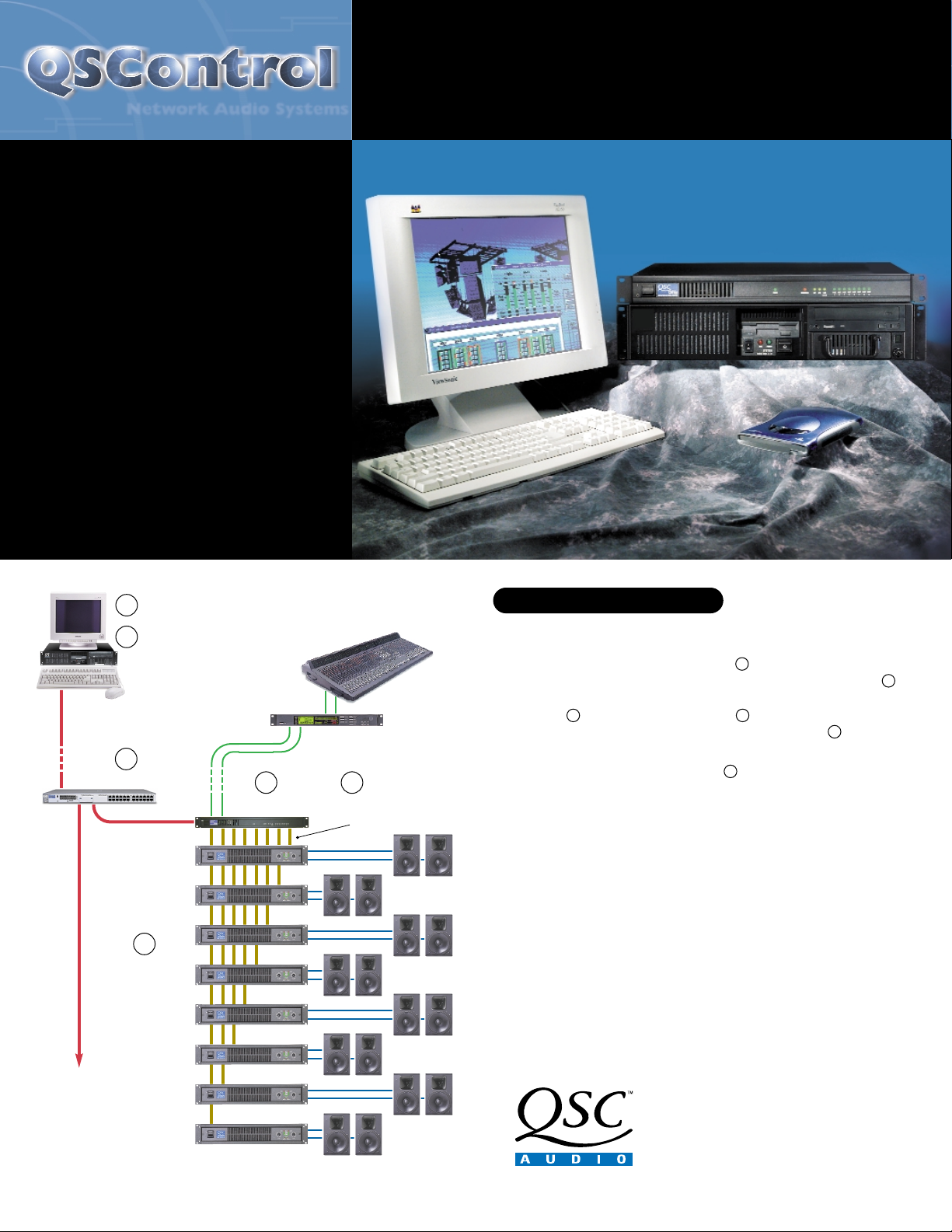
QSControl (pronounced Q’s Control) is a powerful
and flexible system that provides remote
management and diagnostics of QSC amplifiers
and other audio devices over an Ethernet
network—including selected QSC DSP devices,
such as the DSP-3 digital signal processor. You
can monitor and control hundreds of amplifiers
simultaneously, as well as perform a wide range
of advanced functions, including event logging,
real-time monitoring of loudspeaker opens and
shorts, plus configuration of the DSP-3 module.
A QSControl system is composed of a System
Controller (a Microsoft Windows-based PC)
running QSControl Software that is linked via
Ethernet to CM16a Amplifier Network Monitors or
other networked audio devices. Each CM16a
provides sixteen channels of remote level
adjustment and amplifier management for
DataPort-equipped QSC amplifiers.
Key Components of QSControl
CM16a Amplifier Network Monitor
The CM16a Amplifier Network Monitor offers powerful amplifier
management in a QSControl networked audio system, using Ethernet
technology to communicate with the host system controller. The System
Controller uses application software to operate the networked
audio system, including the CM16a units and their amplifiers .
Each CM16a performs monitoring and control functions for QSC DataPortequipped amplifiers using DataPort cables . Further, the CM16a connects
to QSC’s family of digital signal processors such as the DSP-3.
Control Application Software
There are two ways to run QSControl applications on the System Controller.
The first is with System Manager, QSC’s standard application included with
the QSControl system, requiring no user programming. The second is to
create a custom application using the QSControl Development Tools in
Microsoft Visual Basic. Using these tools, the system can be customized to
your specifications.
System Controller
QSControl Software runs on a computer configured with select Microsoft
operating systems—including Windows® 2000. The Graphical User Interface
(GUI) program controls QSC’s and third-party networking products.
NETWORK AUDIO SYSTEMS
Hear the Power of Technology.
1675 MacArthur Boulevard
Costa Mesa, CA 92626
Ph: 800/854-4079 or 714/957-7100
Fax: 714/754-6174
www.qscaudio.com
email: info@qscaudio.com
System Controller
and
QSControl Software
Located either on or off site.
QSC CM16a
QSC Amplifiers
To Additional
Equipment
Typical Audio
Sources and
Processors
Speakers
6
5
1
3
Ethernet Switch
4
DataPort
Cables
2
1
2
3
4
6
5
Page 2
Input / Output Control and Monitoring
■
Input sensitivity selection: 1V or 3V
■
Input source select: Normal/Page
■
Level control
■
Pre-/Post-fader audio signal monitoring
■
Mute control
■
Signal polarity control
■
Pre-/Post-fader signal level metering
Amplifier Output Monitoring
■
Output voltage and current metering
■
Output power in watts
■
Output clip detection monitoring
■
Headroom metering
■
Output signal (speaker terminal) audio monitoring
Load Monitoring
■
Open/shorted load detection
■
Adjustable threshold for detecting load opens and shorts
■
Continuously updated average impedance measurement
Amplifier Management
■
AC standby/operate mode selection
■
AC mode indication (Off/Standby/On)
■
Protect status monitoring
■
Operating temperature metering
■
Overtemp indicator with adjustable overtemp threshold
■
Gain control monitoring
■
Model ID indication
■
Bridge Mono/Parallel/Stereo mode indication
Other Features
■
Fifteen user-definable configuration presets
■
RS-232 port for diagnostics and preset control
■
Internal sine wave signal generator available for system diagnostics
(accessible via Telenet only)
■
Page input with selectable 1V or 3V sensitivity
■
One contact closure input
■
One floating dry-contact SPDT (Single Pole Double Throw) relay output
■
Audio monitor bus with selectable tap points, mixing, and balanced I/O
■
Recessed front panel bypass switch
■
Firmware is updateable via the network to add future upgrades
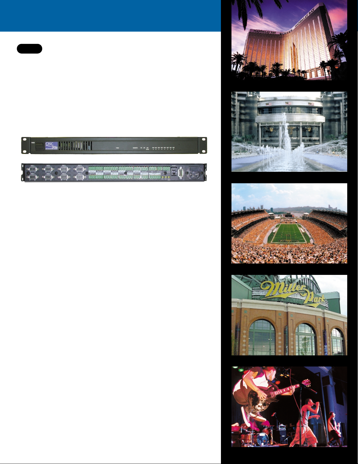
QSControl Amplifier Network Monitor
The CM16a Amplifier Network Monitor is a key hardware component of QSControl, QSC’s
Ethernet-based audio network. Each CM16a provides sixteen channels of audio level control,
monitoring, and amplifier management for DataPort-equipped QSC amplifiers. The CM16a is
operated remotely by a Windows-based PC functioning as the System Controller running
QSControl application software. Control and monitor data is communicated between the System
Controller and CM16a over an Ethernet network. The CM16a, located in the amplifier rack, is linked
to amplifiers via DataPort cables. The CM16a also serves as the network interface for QSC’s digital
signal processors, including the DSP-3.
CM16a
Mandalay Bay Resort, Las Vegas
Petronas Towers, Malaysia
Heinz Field, Pittsburgh
Miller Park, Milwaukee
The Galaxy Theater, California
Page 3

Input Signal
Frequency Response 20 Hz to 20 kHz, ±0.5 dB
10 Hz to 80 kHz, ±3 dB
Distortion <0.01% THD+N @ +4 dBu out
(page input <0.03%)
Dynamic Range >110 dB unweighted (20 Hz–20 kHz)
(page input >100 dB)
Polarity In-phase or reversed
Level Control Range -95.5 to 0 dB in 0.5 dB steps
Precision Attenuator Transients
(“zipper noise”) better than 112 dB below maximum output
Mute >90 dB attenuation
Inputs
Program inputs 16
Paging input 1 Dedicated input with configurable
routing to any or all 16 input sections
Monitor bus input 1
Connector type “Phoenix-style” (a.k.a. “Euro-style”)
detachable terminal blocks
Type Electronically balanced
Grounding All shield terminals connected
to chassis
Nominal level 1V/3V rms selectable (-10 dBV/+4 dBu)
Maximum level +21 dBu
Impedance 25 kΩ balanced
Common-mode rejection Typical, >50 dB, 20 Hz-20 kHz
Worst Case, >40 dB at 20 kHz
Crosstalk (inter-channel
within DataPort pair) >75 dB separation (20 Hz–20 kHz)
Crosstalk (intra-channel
between DataPorts) >90 dB separation, 20 Hz-20 kHz
measured with all inputs and
outputs terminated
Outputs
Program outputs 16 (via HD-15)
Connector type 8 HD-15 DataPort connections
Cable type VGA monitor cable
1
Qualified length 2 meters
Monitor output 1
Connector “Phoenix-style” (a.k.a. “Euro-style”)
detachable terminal blocks
Type Electronically balanced
Grounding Shield terminal connected to chassis
Nominal level +4 dBu
Maximum level +21 dBu
Output impedance 75Ω balanced
Output load 600Ω min
Power Amplifier Output Monitoring
Output Short Detect* Senses load <1Ω for Stereo/Parallel modes;
<2Ω Bridge Mono mode (default threshold)
Threshold is adjustable in software
Output Open Detect* Senses load >60Ω (default threshold)
Threshold is adjustable in software
Output Voltage Meter Range automatically matches to
amplifier model used
Output Current Meter Range automatically matches to
amplifier model used
Amplifier Headroom Reports remaining available power
Amplifier Gain* Calculates and reports amplifier gain
(knob setting)
*Signal level must be higher than -32 dB, referenced to maximum output of amplifier
Power Amplifier Management
Power Amplifier Interface
Compatibility QSC DataPort-equipped amplifiers
Connector and cable HD-15 VGA cable
1
, 2 meters length
2
qualified (for longer runs, contact QSC’s
Technical Services Department)
Amplifiers Up to 16 channels (8 DataPorts) of
QSC DataPort-equipped amplifiers
Amplifier AC Power Control
AC mode control Switches amplifier between operate
and standby mode
AC power indicator Indicates operate, standby, or
power-down mode
Amplifier Status Monitor
Clip indicator Senses channel clip status
Protect indicator Senses amplifier protect status
Temperature meter Reports amplifier operating temperature
Over-temp. alert Software adjustable threshold (80°C default)
Control Room Foldback Monitoring
Number of Signal
Monitoring Buses per CM16a 1
Number of Channels per CM16a 4 (Maximum number assigned
to monitor mix at one time)
Internal Signal Monitor Points
(each with individual level controls)
Pre-fader input signal 16
Post-fader input signal 16
Power amplifier output 16
Monitor Input Summed with internal monitor mix
at unity gain
Monitor in to monitor out 0 dB, ±1 dB
Nominal level +4 dBu
Maximum level +21 dBu
Input impedance 10kΩ balanced
Configuration Active balanced, shield connected to chassis
Common-mode rejection Worst case, >54 dB at 20 Hz rolling off to
>40 dB at 20 kHz
Typical case, >50 dB 20 Hz-20 kHz
Output Sum of external monitor input and signals
from internal monitor mix
Frequency response 20 Hz–20 kHz, ± 0.5 dB
Distortion <.05% THD @ +4 dBu out
Dynamic range >90.5 dB unweighted, 22 Hz–22 kHz
Noise floor -90.5 dB
Nominal level +4 dBu
Maximum level +21 dBu
Output impedance 75Ω balanced
Output load 600Ω min
Configuration Active balanced
RS-232 Port
Cable Type Null-Modem (a.k.a. Laplink), female 9-pin
D-sub chassis connector
Port Settings Bits per Second 9600
Data Bits 8
Parity none
Stop Bits 1
Flow Control Xon/Xoff
Page Input
Specifications
Page 4

Contact Closure Inputs and Outputs
Inputs 1 discrete input
Configuration Single-ended input
Resistance for closure detect < 1kΩ max
Resistance for open detect > 5kΩ min
Input voltage limit 7.000 VDC maximum
(“-” input terminal connected to chassis)
Output 1 discrete output
Configuration Electromechanical relay, dry contacts,
floating, C, NC, NO
Maximum steady-state current 0.5A
Maximum switched current 0.25A
Ground isolation 70V maximum
Connector “Phoenix-style” (a.k.a. “Euro-style”)
detachable terminal block connectors
Network Interface
Physical Network Ethernet
Raw data rate 10 megabits per second
Frame format D.I.X. (Ethernet)
Connector RJ-45 female
Ethernet type 10BASE-T: (via RJ-45)
Cable type 10BASE-T: CAT-3 (or better) twisted pair
Max cable length 10BASE-T: 100 m to hub
Grounding Floating
Transport Network TCP/IP
Internetwork protocol IP
Transport protocol UDP
Application Protocol QSC24
Version 1
Revision 7
General
Physical
Height 1.72" (1RU)
Width 19" (standard rack mount)
Depth 14.84" (37.7 cm), including rear supports
Weight 11 lbs. (5 kg)
Mounting Rear support recommended for portable
or mobile use
Operating Temp. 0 to 50° C
AC Power
Voltage 100-240 VAC (Universal Supply)
Current 1A RMS @ 120V, 1.1A RMS @ 100V,
0.5A RMS @ 230V
Frequency 47–440 Hz
Specifications subject to change.
Architect’s and Engineer’s Specification
The CM16a Amplifier Network Monitor shall provide input, output,
status monitoring, and control for DataPort equipped QSC power
amplifiers in an Ethernet-TCP/IP based network audio system. Sixteen
independent channels shall be provided, grouped in pairs to support up
to sixteen power amplifier channels.
Amplifier Input Control and Monitoring. For each of the sixteen power
amplifier input signals, the CM16a shall provide level, mute and polarity
control, pre- and post-fader signal level metering and audio monitoring,
and selectable +4 dBu/-10 dBV (3V/1V) input sensitivity.
The CM16a shall provide a page input, separate from the normal
program inputs, whose signal may preempt the program signal of any
or all of the sixteen program channels. This input shall have selectable
+4 dBu/-10 dBV (3V/1V) sensitivity.
The CM16a shall provide for the storage and recall of up to sixteen
different presets, numbered 0 through 15. Each preset shall be a
“snapshot” of all of the CM16a functions and settings. Preset #0 shall be
the default boot-up preset.
Amplifier Output Monitoring. For each of the sixteen power amplifier
outputs, the CM16a shall provide clip detect monitoring, short/open
circuit detect, voltage and current metering, amplifier headroom, load
impedance, real output power to load, and audio monitoring of the
voltage signal.
Amplifier Management. For each of the DataPort connected power
amplifiers, the CM16a shall provide AC standby/operate mode control,
AC power state indication, temperature metering, amp gain settings
(front panel knob position with respect to full output), over-temperature
detection, stereo/parallel/bridge-mono indication, amplifier model
detection, and protect status detection (subject to the capabilities of
each amplifier).
Audio Monitoring Chain. For each of the sixteen program channels, the
CM16a shall provide three monitor points as follows: (1) pre-fader level
control, (2) post-fader level control, or (3) power amplifier output. A
channel’s monitor output may be selected from one of these three
signals, or it may be switched off. The signal at the CM16a’s monitor
output connector shall be the sum of the signal at its monitor input
connector and as many as four of the sixteen channel monitor signals
at one time per CM16a. A monitor level control shall be provided for
each monitor tap point to adjust the individual levels of the channel
monitor signals prior to their being mixed with the monitor input signal.
Contact Closure I/O. The CM16a shall provide one trigger contact-closure
sense input which shall also be TTL signal compatible, and one drycontact floating SPDT relay output. These shall be under software control,
with functions definable by the QSControl custom software application.
The contact closure sense input shall be capable of toggling between
presets 14 and 15, regardless of the computer’s connection status.
Data Network. All CM16a functions shall be controlled and monitored
via an Ethernet digital control network using the TCP/IP transport
protocol and the QSC-24 control and monitoring application protocol.
Rear-panel connections shall be provided for 10BASE-T Ethernet
utilizing a standard RJ-45 Unshielded Twisted Pair Category-5
connection. Other than the AC power and bypass switches, the CM16a
shall have no manual controls. A 9-pin, “D” subminiature connector
shall be provided to allow interfacing to an RS-232 connection. This
connector shall be used for CM16a setup, testing, diagnostics, and
limited control functions.
Amplifier Interface. The CM16a’s interface to each power amplifier
DataPort shall be via a HD-15 connector. The amplifier interface shall
use a standard personal computer Video Graphics Adapter (VGA) CRT
monitor cable
1
. This interface shall transmit two amplifier input audio
signals as well as all control and monitoring signals. Special signal
conditioning and grounding techniques shall be used in this interface to
ensure negligible levels of noise and crosstalk.
General. All audio inputs and outputs shall be balanced with a nominal
input level of +4 dBu and maximum level of +21 dBu. Input connectors
shall be of the “Euro-style” depluggable barrier strip type.
1
QSC DataPort cable required for connection with QSC DSP devices.
2
For lengths greater than 2 meters, a QSC DataPort cable is recommended.
Page 5

Block Diagram of the CM16a
QSControl Network Audio Systems
Processor 866 MHz Intel Pentium™ III processor
RAM 128 MB, 133 MHz bus
Hard Disk 4 GB or greater Ultra DMA
Floppy 3.5" 1.44 MB drive
CD-Rom 40x or greater IDE
Network 10/100
BASE-T
Network Configuration TCP/IP host
Modem 56k V.90 internal PCI (optional)
Video 2D/3D Graphics, 133/100 MHz, 4 MB Display cache or better
Sound Sound Blaster® compatible (optional)
Keyboard 104 key, PS/2 compatible
Mouse PS/2 compatible
Operating System Windows NT-4 (SP-6) or Windows 2000 (SP-2)
All specifications are subject to change.
Minimum Recommended Specifications for the System Controller
Audio
Inputs
Power
Status
Detect
Amp
Model
Detect
Amp Functions
Page
Port A Ch 1
Port A Ch 2
Standby /
Operate
Control
Bridge
Mode
Detect
Input
Input
Sensitivity
3V / 1V
Input
Sensitivity
3V / 1V
Output
Open
Detect
Output
Open
Detect
Input
Sensitivity
3V / 1V
Internal DAC
(for Test Tones
and Playback)
Output
Short
Detect
Output
Short
Detect
Input
Source
Normal
/ Page
Input
Source
Normal
/ Page
Parallel
Stereo Mode
Protect
Status
Detect
Protect
Status
Detect
Monitor
Monitor
Load
Detect
Load
Detect
Meter
Mon (Pre)
Meter
Mon (Pre)
Real
Power
Detect
Real
Power
Detect
Level Control
-95.5 to 0 dB
0.5 dB steps
Level Control
-95.5 to 0 dB
0.5 dB steps
Clip
Detect
Clip
Detect
Amp
Gain
Detect
Amp
Gain
Detect
DataPort A
DataPorts B through H (same as DataPort A)
Audio Monitor Chain
(Summing Bus)
From
Mon
Tap Points
Mon 1
Mon 2
Mon 3
Mon 4
Up to four signals may be
sent to the Monitor Bus at
one time. Each tap has
its own gain adjust.
Mute Polarity
Mute Polarity
Overtemp
Detect
Overtemp
Detect
Heat-
sink
Temp
Heat-
sink
Temp
Meter
Mon (Post)
Meter
Mon (Post)
Head-
room
Meter
Head-
room
Meter
RLY
Output
Current
Meter
Output
Current
Meter
Ch 1
Ch 2
Output
Voltage
Meter
Output
Voltage
Meter
C
RLY
Trig in
NCNO
Ch 1
Functions
Mon (Amp)
Mon (Amp)
Ch 2
Functions
Contact
Closure
RLY
Out
I/O
Power Amplifier DataPort Interface
Monitor
Chain
Input Output
RS-232 Ethernet
Serial I/O (DB-9)
Micro-Controller
Monitor
Chain
Internal
Page 6

QSControl Software
QSControl Software allows you to view and adjust signal controls with
the click of a mouse. You can use System Manager, a standard
application included with QSControl Software, or design a custom
application tailored to your specific needs with easy-to-use Visual Basic.
QSControl Software significantly expands the system’s overall
capabilities. Users can now create custom applications with “drag-anddrop” programming, minimizing the need to write code. In addition to
amplifier management, users can control additional audio components
including MIDI devices. A QSControl system can also be accessed and
controlled by multiple System Controllers from multiple locations.
The software supports the CM16a Amplifier Network Monitor, a
1RU unit that links the PC to networked QSC amplifiers to provide remote
control and monitoring functions. The CM16a enables QSControl’s
amplifier monitoring functions by allowing users to adjust thresholds for
detecting load opens and shorts, monitor average load impedance, monitor
amplifier output in watts, and view amplifier headroom. The CM16a
supports all QSC DataPort-equipped amplifiers, including the 4- and 8channel models. The QSControl architecture supports network
communications of QSC’s digital signal processors, such as the DSP-3, via
CM16a DataPorts. Users can also apply future CM16a firmware updates
quickly and easily from a remote PC via Ethernet.
System Manager
System Manager requires no programming whatsoever to operate the
system. You can perform comprehensive signal metering and gain
adjustment for each amplifier:
■
Adjust input sensitivity for 3-volts or 1-volt
■
Adjust input levels to the amplifier
■
Meter pre-fader and post-fader levels
■
Invert the signal polarity
■
Override each channel with an auxiliary input that can be used
for emergency paging
■
Fold back audio to the front-of-house or control position from
selectable points in the audio chain: pre-fader, post-fader,
or the amplifier output
■
Up to sixteen configuration presets can be recalled automatically
You can also perform comprehensive amplifier management:
■
Control amplifier power state (On/Standby)
■
Monitor amplifier status including clip, protect, and operating
temperature
■
Monitor amplifier output including voltage, current, power in
watts, and headroom
■
Load status, including average load resistance and adjustable
thresholds for detecting loudspeaker opens and shorts
■
Amplifier configuration, including gain control settings and
stereo, parallel, or bridge mode
■
Monitor amplifier’s power status and AC standby mode
System Manager also provides an Event Log that allows you to keep
track of system events such as amplifier clipping, protect modes,
loudspeaker opens and shorts, and other conditions. These text files can
be saved for future reference or downloaded remotely via modem.
When any event occurs, System Manager automatically notifies you with
a flashing icon.
Custom Applications
Operate QSControl with System Manager, our standard control application
included with QSControl Software, or create a custom application to meet
your specific needs. Using standard Windows tools such as ActiveX , COM,
and plug-in components for Microsoft Visual Basic, QSControl offers the
most user-friendly and advanced development tools available today.
QSControl’s “open architecture” also allows the control of other
manufacturer’s devices using RS-232, MIDI, Ethernet, or other interfaces
for a single integrated solution using standard development tools such as
Microsoft Visual Basic.
QSControl’s improved
System Manager requires
no programming to
configure and control your
system. Features include
an Event Log for tracking
system changes and status
of amplifiers.
Using Microsoft’s Visual
Basic, custom screens
and panels can be
created to display and
control all aspects of
your system. You can
even control 3rd party
gear over MIDI, RS-232,
Ethernet, etc.
Benefits of a Custom Application
■
Build simple control screens that can perform complex functions.
■
Create a full range of system-wide presets that are available for
different operating modes in multipurpose venues.
■
Perform pre-programmed functions at designated times—without an
operator present. For example, perform basic diagnostic checks at
night, log the results, and power the system down.
■
Control non-QSC equipment via Ethernet, MIDI, contact closures,
RS-232 or other interfaces for a single integrated solution.
■
Automate performance monitoring and maintenance. For example,
alert the operator whenever a loudspeaker circuit becomes open or
shorted, mute the power amplifier, and log an error message for
maintenance personnel.
■
Provide a comprehensive set of fire and emergency mode functions
that are invoked by an external contact closure or other simple signal.
■
Employ full, multi-level password security, allowing only authorized
personnel access to certain control functions.
QSControl Spec Sheet 02/05/02
 Loading...