

Page 1
TM
AcousticDesign
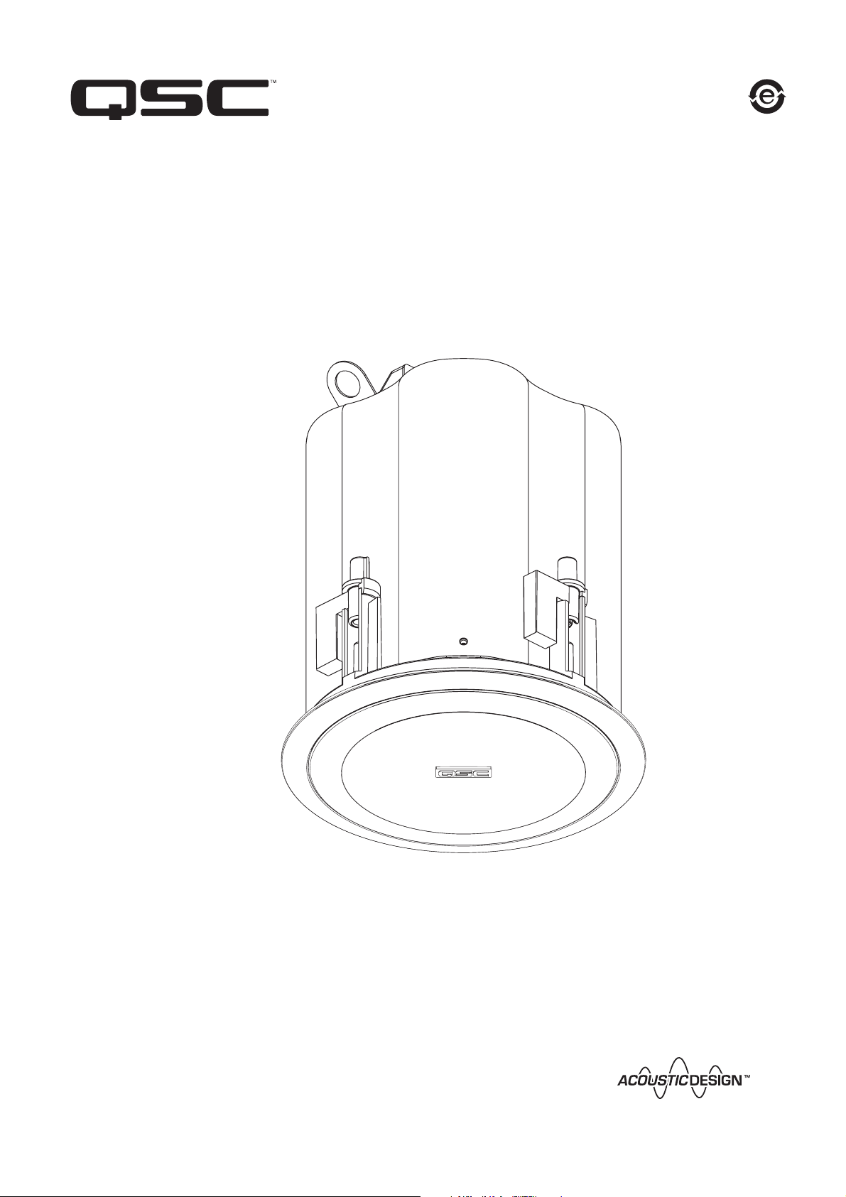
In-ceiling Loudspeakers User Manual
AD-C42T
105 mm (4”) two-way
*TD-000263-00*
TD-000263-00-A
Page 2
IMPORTANT SAFETY PRECAUTIONS
& EXPLANATION OF SYMBOLS
1- Read these instructions.
2- Keep these instructions.
3- Heed all warnings.
4- Follow all instructions.
5- Clean only with a dry cloth.
6- Install in accordance with QSC Audio Product’s instructions and a licensed, professional engineer.
7- Do not install near any heat sources such as radiators, heat registers, stoves, or other apparatus (including amplifiers)
that produce heat.
8- Only use attachments/accessories from QSC Audio Products, Inc.
9- Use only with mounts or brackets specified by QSC Audio Products.
10- Refer all servicing to qualified personnel. Servicing is required when the apparatus has been damaged in any way.
The lightning flash with arrowhead symbol within an equilateral triangle is intended to alert the user to the
presence of uninsulated “dangerous” voltage within the product’s enclosure that may be of sufficient magnitude to constitute a risk of electric shock to humans.
The exclamation point within an equilateral triangle is intended to alert the user to the presence of important
operating and maintenance (servicing) instructions in this manual.
WARNING! Before placing, installing, rigging, or suspending any speaker product, inspect all
hardware, suspension, cabinets, transducers, brackets and associated equipment for damage.
Any missing, corroded, deformed or non-load rated component could significantly reduce the
strength of the installation, placement, or array. Any such condition severely reduces the safety of
the installation and should be immediately corrected. Use only hardware which is rated for the
loading conditions of the installation and any possible short-term unexpected overloading. Never
exceed the rating of the hardware or equipment. Consult a licensed, professional engineer when
any doubt or questions arise regarding a physical equipment installation.
Warranty (USA only; other countries, see your dealer or distributor)
Disclaimer
QSC Audio Products, Inc. is not liable for any damage to amplifiers, or any other equipment that is caused by negligence or improper
installation and/or use of this loudspeaker product.
QSC Audio Products 3 Year Limited Warranty
QSC Audio Products, Inc. (“QSC”) guarantees its products to be free from defective material and / or workmanship for a period of three
(3) years from date of sale, and will replace defective parts and repair malfunctioning products under this warranty when the defect
occurs under normal installation and use - provided the unit is returned to our factory or one of our authorized service stations via prepaid transportation with a copy of proof of purchase (i.e., sales receipt). This warranty provides that the examination of the return product must indicate, in our judgment, a manufacturing defect. This warranty does not extend to any product which has been subjected to
misuse, neglect, accident, improper installation, or where the date code has been removed or defaced. QSC shall not be liable for incidental and/or consequential damages. This warranty gives you specific legal rights. This limited warranty is freely transferable during
the term of the warranty period.
Customer may have additional rights, which vary from state to state.
In the event that this product was manufactured for export and sale outside of the United States or its territories, then this limited warranty shall not apply. Removal of the serial number on this product, or purchase of this product from an unauthorized dealer, will void
this limited warranty.
Periodically, this warranty is updated. To obtain the most recent version of QSC’s warranty statement, please visit www.qscaudio.com.
Contact us at 800-854-4079 or visit our web site at www.qscaudio.com.
© Copyright 2007, QSC Audio Products, Inc.
QSC® is a registered trademark of QSC Audio Products, Inc.
“QSC” and the QSC logo are registered with the U.S. Patent and Trademark Office
All trademarks are the property of their respective owners.
Page 3
Introduction
Congratulations and thank you for your ceiling loudspeaker purchase. The AD-C42T models offer excellent acoustic performance in an easy-to-install and attractive package.
Please review these instructions carefully and follow the recommendations. Consult a
licensed installation professional if you are uncertain about any mounting issues.
The AD-C42T models feature a 4” low frequency (LF) driver and a 3/4” dome high frequency (HF) driver. The AD-C42T are equipped with an audio transformer suitable for 70V
and 100V distributed systems, as well as a tap-selector switch which can bypass the
transformer for 8 ohm applications.
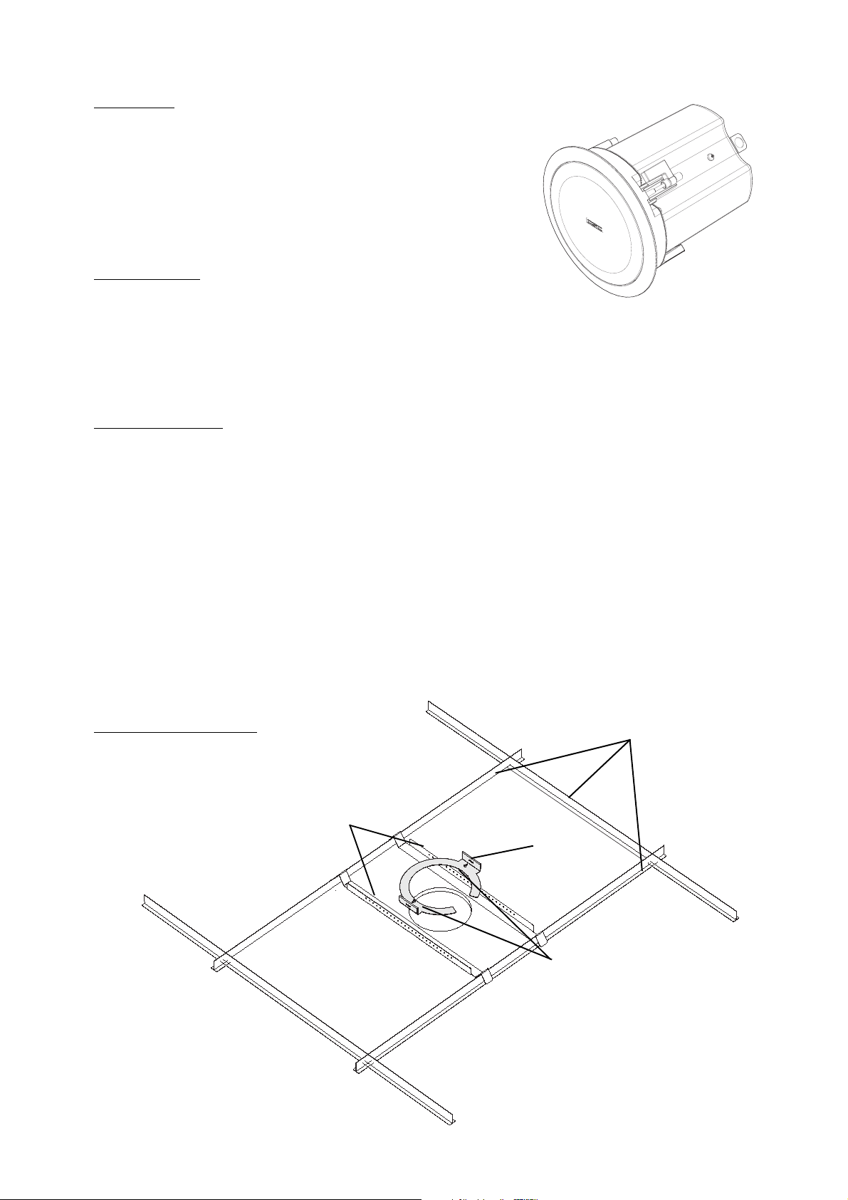
What’s Included
Your ceiling loudspeaker box contains: - two loudspeaker cabinets
- two protective grill assemblies
- four support brackets for suspended ceiling installations
- two C-ring bracket for suspended ceilings and other ceiling reinforcing applications
- Self-tapping screws (M4.2 X 1.4 X 10mm) for securing the C-ring-to-support brackets
- two grill clips used for clipping the plastic grill retaining lines together
- two phoenix connector assemblies for connecting signal and daisy-chaining
- two paint shields
- two grille cloths
Installation Options
The AcousticDesign in-ceiling loudspeakers can be mounted in suspended ceilings, as well as non-suspended types. We recommend an
installation professional be consulted for safety assurance, quality installation, and optimum acoustic performance.
For suspended ceiling applications, the suspended ceiling support brackets must be used with the C-ring bracket. The suspended ceiling
support brackets are designed to accommodate 24” or 600 mm t-channel grid spacing. The brackets do not attach to the t-channel; the
angled “V” bend sits over the t-channel and will catch the t-channel in the event of a tile failure or fall-out.
For other ceiling types, the C-ring bracket can be used to reinforce the mounting surface. If the ceiling is suitably strong, the loudspeaker can be secured in the cutout hole without additional reinforcement.
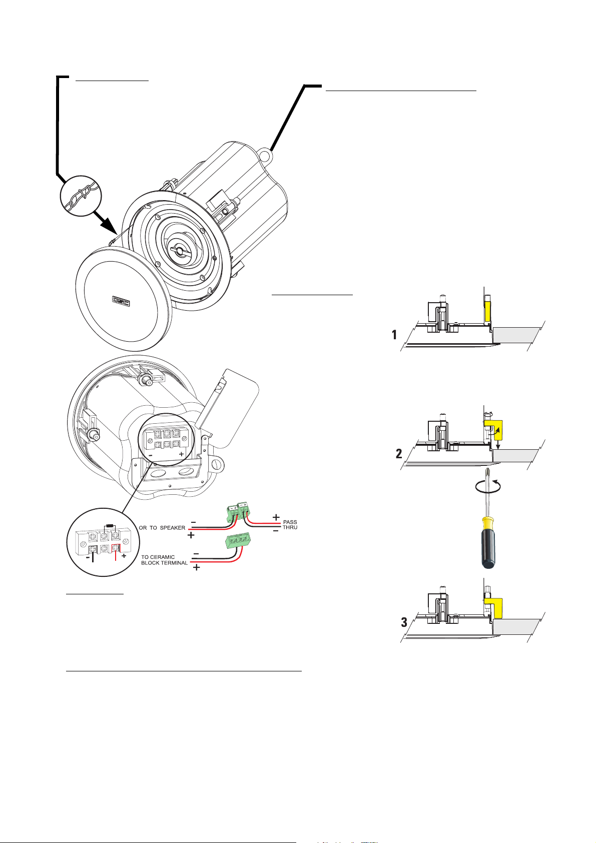
Audio connections are made directly to the ceramic terimainal block or by using Phoenix terminal block type connectors. Two sets of
terminals are provided; one set for the signal connection and another for pass-through (or daisy chain) connection to other loudspeakers
on the same distribution circuit.
Two safety features are provided, an enclosure-retaining safety tab and a grill-retaining safety tether. The enclosure tab is a metal tab
near or on top of the enclosure suitable for securing the loudspeaker to building framing; this provides maximum safety in the event the
supporting structure should fail.
Hardware Nomenclature
Suspended ceiling viewed from above.
(hardware may not be required for all installations)
Support Brackets
C-ring Bracket
Existing Suspended
Ceiling “T-Bars”
Screws
Page 4
Grill Safety Clip
The cabinet and the grill both have a small loop of
plastic line. The grill’s loop has a clip attached.
Using the grill clip, attach the grill to the cabinet’s
loop. This will help prevent the grill from falling
should it become detached.
Use the Secondary Support Tab!
Loudspeakers can potentially generate substantial vibration. In addition to ensuring all hardware is properly
installed and secured, you must use the secondary support
tab on the enclosure to secure the loudspeaker to an appropriate structural support. This will minimize the chance of
the loudspeaker falling from the ceiling in the event the primary mount fails. Any cable or wire used as a secondary
support line must be strong enough to support several times
the weight of the loudspeaker. Do not use rope, string,
twine or other textile-based line in the secondary support
system as it is easily cut or burned. The secondary support
attachment point and any fasteners used on the building’s
structure must also be strong enough to support several
times the weight of the loudspeaker.
Mounting Clamps
The mounting clamps are part of
the assembly for simple use. Do
not install the grill until clamps
have been tightened and any
adjustments made.
Before inserting the cabinet into
the mounting cutout, make sure
the clamps are folded in against
the cabinet, see 1, right.
After the cabinet is installed into
the mounting cutout, tighten each
clamp’s screw using a #2 Phillips
screwdriver, see 2, right.
The clamp rotates 90° and is then
pulled tight by the screw, see 3,
right.
Connections
Connect signal wires to ceramic terminal block noting correct polarity or to the supplied
plastic terminal block assembly. When using the plastic terminal assembly connect the
four pin receptacle to the ceramic block observing polarity. Connect the signal wires to
the screw terminals of one of two pin plugs observing correct polarity. The other two
pin plugs can then be used as pass through to daisy chain the signal to another speaker
or it can be left unused.
Other Recommendations and Important Information
•Grill removal: The grill can be removed by carefully prying around its outer edge or inserting a small, metal pin or hook into the
grill’s openings and pulling evenly around its perimeter.
•If rattles or buzzing is heard during operation, it may be necessary to put vibration dampening material between the support
rails and the ceiling tiles and/or t-channels.
•The support rails have holes along their usable length to attach the C-ring bracket. This allows for the cutout to be placed in
many positions along the ceiling tile width.
Page 5

Installation Procedure
1- Using the included C-ring or the dimensions provided, trace a cutout pattern onto the
ceiling surface.
2- Cut the mounting hole. Use a sharp tool to avoid stressing or cracking the mounting surface.
3- Pull the wires through the hole.
4- Pass the two suspended ceiling support brackets through the hole and place as shown
in the illustration. Make sure the part of the bracket that is flat against the tile is toward
the hole. If installing in a non-suspended ceiling application, these brackets are not
required.
5- Pass the C-ring bracket through the hole. Slide the cutout slot into the hole first, and
then rotate the bracket so it passes through the hole. Be sure the wires pass through the
ring.
6- Position the support brackets, and secure the C-ring bracket to each of the support
brackets using the screws provided. If installing in a non-suspended ceiling application,
skip this step.
7- Loosen the connection cover plate retaining screw and swing the cover open. Install an
fitting into the hole provided on the cover plate.
8- Temporarily support the enclosure so the wires may be passed through the enclosure
top with enough slack to prepare and terminate the wires.
9- Locate the terminal block connectors included with the loudspeaker. Loosen the wire
retaining screws fully.
10- Strip the wire ends approximately 10 mm (0.4”) and insert each wire into its proper
connector position. Tighten the wire retaining screws fully.
11- Rotate the connection cover plate closed, making sure not to stress the connections or
pinch the wires. Tighten the cover plate’s retaining screw.
12- Adjust the wiring at the entry point, if necessary, and properly secure fitting. This prevents wire stress and strain from pulling the connections/connectors loose.
13- Attach a safety cable (secondary support cable) from the enclosure’s attachment tab to
an appropriate support point. This cable and the attachment points must be strong enough
to support many times the weight of the loudspeaker in the event the primary mounting
system fails.
14- Insert the enclosure into the ceiling cutout, making sure any brackets used remain
properly positioned. Tighten the loudspeaker’s mounting clamp screws.
15- Set the tap selector switch to the desired position. 70V systems, all four positions may
be used. Do not use highest tap setting with 100V systems. 8 ohm systems, selector to 8
ohm position.
16- Make sure all tests and adjustments are complete before installing the grills. Locate
the loudspeaker’s grill. The cabinet and the grill both have a small loop of plastic line.
Using the clip on the grill’s line, attach the grill’s safety loop to the cabinet’s loop. Carefully
work the grill into its retaining slot and press firmly into place. Work the grill in slowly and
evenly to avoid damage. Make sure all tests and adjustments are complete before installing the grills.
Page 6

Specifications
AD-C42T
Frequency Response1: 100- 20k Hz (-3 dB), 85- 20k Hz (-10 dB)
2
Maximum Output
(calculated) 107 dB SPL peak output
Transducers: LF: 105 mm (4”), 19 mm (0.75”) voice coil;
Nominal Coverage: 100° conical (average 2.5 kHz - 10 kHz)
Impedance (ohms): 8.0 nom./ 6.7 min. @ 300 Hz.
Power Rating
rms (IEC 100 hrs): 40 watts rms (30 watts, AD-C42T)
recommended amp power: 80 watts rms, maximum
Sensitivity: 85.0 dB, 1 watt, 1 meter, flush mounted (2 pi)
Bass Loading: sealed
Optional Processing: 100 to 125 Hz. high pass >12 dB/octave
: 101 dB SPL continuous rms output
weatherproof, low-distortion polypropylene cone.
HF: 19mm (0.75”) titanium dome, neodymium magnet.
3
:
Dimensions: see drawings
Net Weight: AD-C42T: 2.7 kg (6.0 lb.)
Enclosure: Corrosion-resistant power coated steel enclosure with injection-molded plastic baffle. Press on metal
grille
Mounting System: Captive, integral mounting clamps. Insert enclosure into cutout, and tighten. Suspended ceiling C-ring
and support bars included.
Connectors: Ceramic block connector inputs and terminal block “through” connectors (rated for 400W max).
Controls: Transformer “tap” selector/ bypass (8 ohm) switch, settings: 3.8, 7.5, 15, and 30 watts (7.5, 15, 30 watts
for 100V) and 8 ohms. Averaged over 50Hz - 20kHz bandwidth (30W tap).
Transformer Distortion: less than .01% THD above 100Hz, 0.2% @ 50Hz (30W tap). Bandwidth: 40 - 20k
Hz (-1dB, all taps).
Agency Listings: CE, UL 1480 (commercial/professional use, outdoor damp), UL 2043 (air handling spaces).
Specification Notes:
1- All frequency ranges specified refer to measured half-space response (2 pi).
2- Calculated maximum peak SPL at 1 m, half-space, speaker operating at rated rms power pink noise input, 50 Hz to 20 kHz.
3- Maximum input power tested in accordance with IEC recommendations; 50 Hz to 20 kHz band limiting, 6 dB signal crest factor.
For detailed information, visit QSC’s web site at http://www.qscaudio.com or call us at 1-800-854-4079 (toll-free USA only)
Specifications are subject to change without notice.
Page 7

AD-C42T Dimensions
CUTOUT HOLE DIAMETER = 191 mm (7.50") USE C-RING FOR TEMPLATE
MATERIAL THICKNESS RANGE FOR CLAMP MOUNTING = 5.6 - 19.0 mm (0.22" - 0.75")
Page 8

How to Contact QSC Audio Products
Cómo comunicarse con QSC Audio Products
Comment prendre contact avec QSC Audio Products
Kontaktinformationen für QSC Audio Products
联系 QSC Audio Products
Mailing address: QSC Audio Products, Inc.
1675 MacArthur Boulevard
Costa Mesa, CA 92626-1468 USA
Telephone Numbers:
Main Number (714) 754-6175
Sales & Marketing (714) 957-7100 or toll free (USA only) (800) 854-4079
Customer Service (714) 957-7150 or toll free (USA only) (800) 772-2834
Facsimile Numbers:
Sales & Marketing FAX (714) 754-6174
Customer Service FAX (714) 754-6173
World Wide Web: www.qscaudio.com
E-mail:info@qscaudio.com
service@qscaudio.com
QSC Audio Products, Inc. 1675 MacArthur Boulevard Costa Mesa, California 92626 USA
©2007, “QSC” and the QSC logo are registered with the U.S. Patent and Trademark Office.
 Loading...