

QSC RAVE-81-S Owners manual
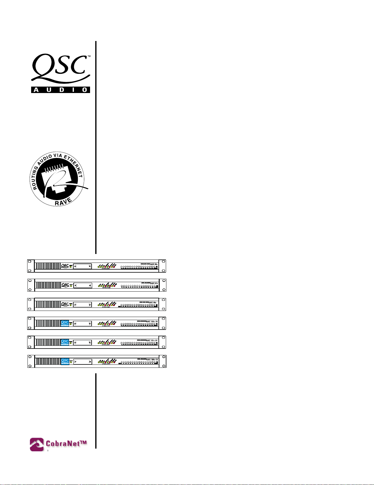
RAVE
“S” series Digital Audio Router
USER MANUAL
▼▼
▼
RAVE 80s
▼▼
▼▼
▼
RAVE 81s
▼▼
▼▼
▼
RAVE 88s
▼▼
▼▼
▼
RAVE 160s-24
▼▼
▼▼
▼
RAVE 161s-24
▼▼
▼▼
▼
RAVE 188s-24
▼▼
(8 AES3 outputs)
(8 AES3 inputs)
(4 AES3 inputs + 4 AES3 outputs)
(16 analog audio outputs)
(16 analog audio inputs)
(8 analog audio ins + 8 analog audio outs)
TD-000070-00
Rev. C
*TD-000070-00*
1
Attention!
•Maximum operating ambient temperature is 65° C.
•Never restrict the airflow throught the devices’ fans
or vents.
•When installing equipment into a rack, distribute
the units evenly. Otherwise, hazardous conditions
may be created by an uneven weight distribution.
•Connect the unit only to a properly rated supply
circuit.
•Reliable Earthing (Grounding) of Rack-Mounted
Equipment should be maintained.
EXPLANATION OF GRAPHICAL
SYMBOLS
The lightning flash with arrowhead symbol,
within an equilateral triangle, is intended to
alert the user to the presence of uninsulated
“dangerous voltage” within the product’s enclosure that may be of sufficient magnitude to
constitute a risk of electric shock to humans.
The exclamation point within an equilateral
triangle is intended to alert the users to the
presence of important operating and maintenance (servicing) instructions in the literature accompanying the product.
EXPLICATION DES
SYMBOLES GRAPHIQUES
Le symbole éclair avec point de flèche à
l’intrérieur d’un triangle équilatéral est utilisé
pour alerter l’utilisateur de la presence à
l’intérieur du coffret de “voltage dangereux”
non isolé d’ampleur suffisante pour constituer
un risque d’elétrocution.
Le point d’exclamation à l’intérieur d’un triangle équilatéral est employé pour alerter les
utilisateurs de la présence d’instructions
importantes pour le fonctionnement et
l’entretien (service) dans le livret d’instruction
accompagnant l’appareil.
ERKLÄRUNG DER GRAPHISCHEN
SYMBOLE
Der Blitz nach unten zeigendem Pfeil in einem
gleichseitigen Dreieck weist den Benutzer auf
das Vorhandensein einer unisolierten,
gefährlichen Spannung“ im Gehäuse hin, die
”
stark sein kann, einer Person einen elektrischen
Schlag zu versetzen.
Das Ausrufzeichen in einem gleichseitigen
Dreieck weist den Benutzer auf wichtige
Betriebs- und Wartungs- vorschriften in den
beiliegenden Unterlagen des Gerätes hin.
CAUTION
RISK OF ELECTRIC SHOCK
DO NOT OPEN
CAUTION: To reduce the risk of electric shock, do not remove the
cover. No user-serviceable parts inside. Refer servicing to qualified service personnel.
WARNING: To prevent fire or electric shock, do not expose this
equipment to rain or moisture.
AVIS
RISQUE DE CHOC ÉLECTRIQUE
NE PAS OUVRIR
ATTENTION: Pour eviter les risques de choc électrique, ne pas
enlever le courvercle. Aucun entretien de pièces intérieures par
l’usager. Confier l’entretien au personnel qualifié.
AVIS: Pour eviter les risques d’incendie ou d’électrocution,
n’exposez pas cet article à la pluie ou a l’humidité.
VORSICHT
GEFAHR EINES ELEKTRISCHEN
SCHLAGES. NICHT ÖFFNEN!
VORSICHT: Um das Risiko eines elektrischen Schlages zu
vermindern, Abdeckung nicht entfernen! Keine Benutzer
Wartungsteile im Innern. Wartung nur durch qualifiertes
Wartungspersonal.
WARNUNG: Zur vermeidung von Feuer oder elektrischen
Schlägen, das Gerät nicht mit Regen oder Feuchtigkeit in
Berührung bringen!
SAFEGUARDS
Electrical energy can perform many useful functions. This
unit has been engineered and manufactured to assure your
personal safety. Improper use can result in potential electrical shock or fire hazards. In order not to defeat the
safeguards, observe the following instructions for its installation, use and servicing.
PRECAUTIONS
L’énergie électrique peut remplir de nombreuses fonctions
utiles. Cet appariel a été conçu et réalisé pour assurer une
sécurité personnelle entiére. Une utilisation impropre peut
entraîner des risques d’électrocution ou d’incendie. Dans le
but de ne pas rendre inutiles les mesures de sécurité, bien
observer les instructions suivantes pour l’installation,
l’utilisation et l’entretien de l’appareil.
FEDERAL
COMMUNICATIONS
COMMISSION
(FCC)
INFORMATION
NOTE: This equipment has
been tested and found to comply with the limits for a Class
A digital device, pursuant to
Part 15 of the FCC Rules.
These limits are designed to
provide reasonable protection
against harmful interference
in a commercial installation.
This equipment generates,
uses, and can radiate radio
frequency energy and, if not
installed and used in accordance with the instructions,
may cause harmful interference to radio communications. Operation of this equipment in a residential area is
likely to cause harmful interference, in which case the
user will be required to correct the interference at his or
her own expense.
© Copyright 2002 QSC Audio Products, Inc. All rights reserved.
“QSC” and the QSC logo are registered with the U.S. Patent and Trademark Office.
RAVE™ is a trademark of QSC Audio Products, Inc. CobraNet™ is a trademark of Peak Audio, Inc.
2

Table of Contents
RAVE “S” Series Digital Audio Router User Manual
Warning Notices................................................................................................................................................. 2
Introduction ......................................................................................................................................................... 4
Illustration of RAVE unit ................................................................................................................................. 5
Glossary .......................................................................................................................................................... 6
How it works .................................................................................................................................................. 8
Channel routing ............................................................................................................................................ 10
Installation ......................................................................................................................................................... 11
Pre-Installation preparation: analog signal levels (RAVE 160/161/188s only) ........................................... 11
Rack mounting .............................................................................................................................................. 13
Connections ....................................................................................................................................................... 13
Ethernet connection ..................................................................................................................................... 13
Analog audio connections (RAVE 160/161/188 only) .................................................................................. 14
Digital audio connections (RAVE 80/81/88 only)......................................................................................... 15
AC power ...................................................................................................................................................... 16
Master/Sync output ..................................................................................................................................... 16
Slave/Sync input ......................................................................................................................................... 16
RS-232 port .................................................................................................................................................. 17
Synchronizing to an AES3 (AES/EBU) stream................................................................................................18
Operation ............................................................................................................................................................ 20
Network activity/status indicators .............................................................................................................. 20
Channel audio signal indicators ................................................................................................................... 22
Program and software “kill” mode .............................................................................................................. 24
Routing ......................................................................................................................................................... 24
Network Design Considerations ................................................................................................................... 26
Specifications ................................................................................................................................................... 29
Appendix ............................................................................................................................................................ 32
Ethernet Cabling ........................................................................................................................................... 32
RS-232 Port Information ............................................................................................................................... 32
Resources ..................................................................................................................................................... 33
How to contact QSC Audio Products and Warranty Information............................................................ 34
Note: Page numbering starts with cover as page 1. This is done to keep electronically-distributed document
page numbering synchronized with the printed document.
3
INTRODUCTION: Overview
RAVE™ Digital Audio Router products provide a means of
transporting CobraNet™ audio signals over a Fast Ethernet
network. Using standard network hardware and physical me-
dia, a RAVE system has a maximum capacity of 64 audio chan-
nels on a 100BASE-TX repeater segment and the ability to
support hundreds of audio channels on a switched Ethernet
LAN. RAVE transports the audio signals over the network in a
standard uncompressed 48 kHz digital format in resolutions
of 16, 20 or 24-bit. Additionally, RAVE products support op-
eration in stand-alone mode, requiring minimal front-panel
setup, or in software mode, utilizing off-the-shelf applications
implementing the Simple Network Management Protocol, or
SNMP.
A RAVE system handles routing in bundles of up to 8 indi-
vidual audio channels. Each RAVE supports up to two bundles
of audio. The availability of audio through network transmis-
sion or reception is dependent on the RAVE model. The 88s
and 188s-24 can both receive and transmit data over the net-
work and can support higher capacity configurations when
setup through the Management Interface using SNMP.
Each RAVE unit has a female RJ-45 Ethernet connector on its
rear panel for connecting to a standard Category 5 Unshielded
Twisted Pair (UTP) cable. For economy and flexibility, RAVE
utilizes standard off-the-shelf Fast Ethernet devices such as
repeaters, switches and fiber optic media converters. You need
at least two RAVE devices—one to send and one to receive,
or two that operate bi-directionally—to route audio over an
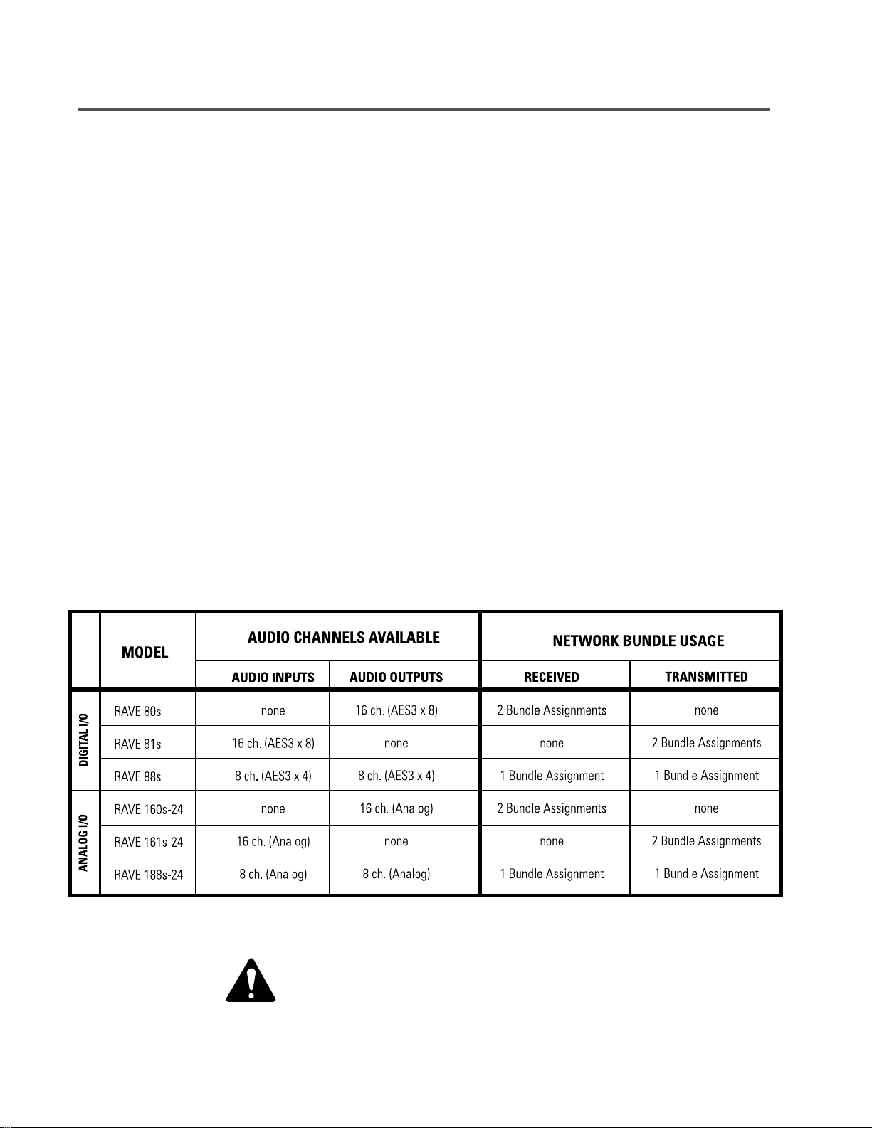
Ethernet network. There are currently six RAVE models, with
three basic send/receive configurations (16 channels send,
16 channels receive, or 8 channels send/8 channels receive).
Each of these configurations is available with either analog
or digital AES3 (often called AES/EBU) audio inputs and out-
puts. The six models are listed in the table below:
NOTE! Many instances of RAVE model numbers, as presented in this manual,
have had the suffix (“s” or “s-24” ) removed for clarity and ease of reading.
4
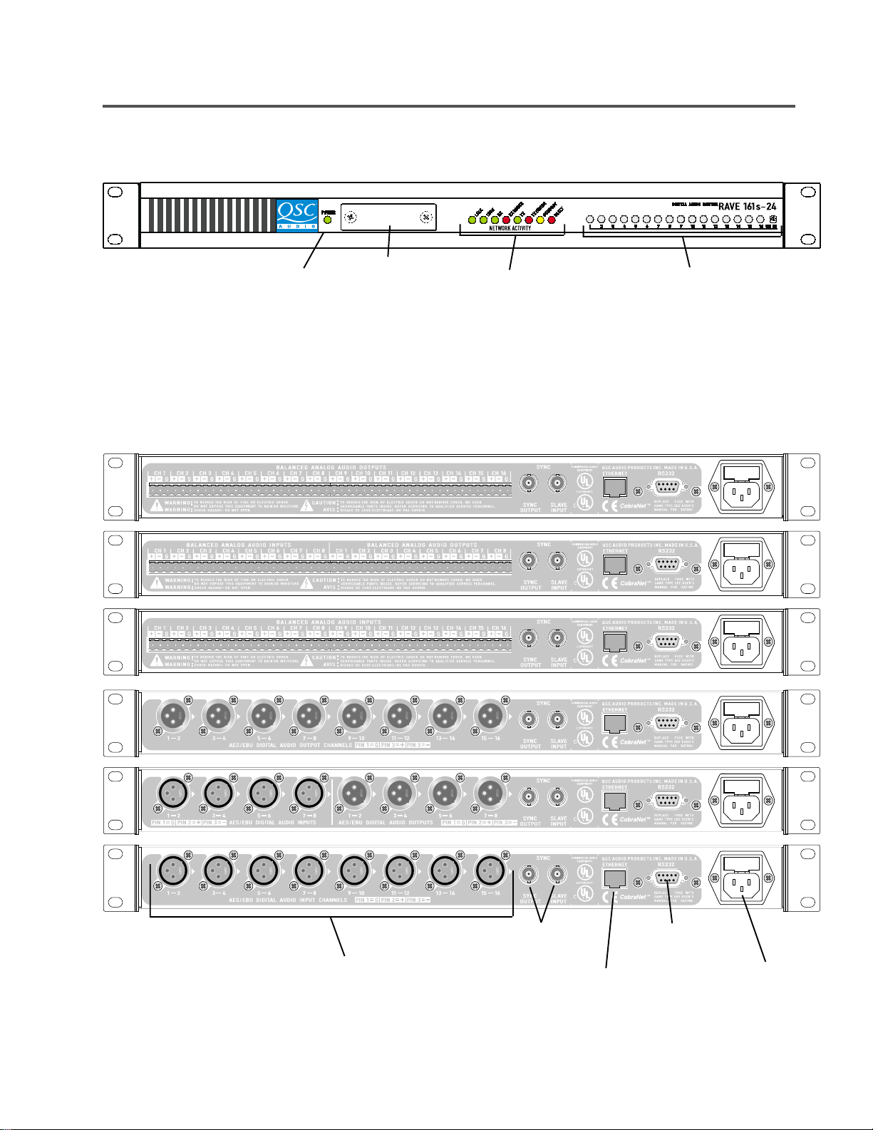
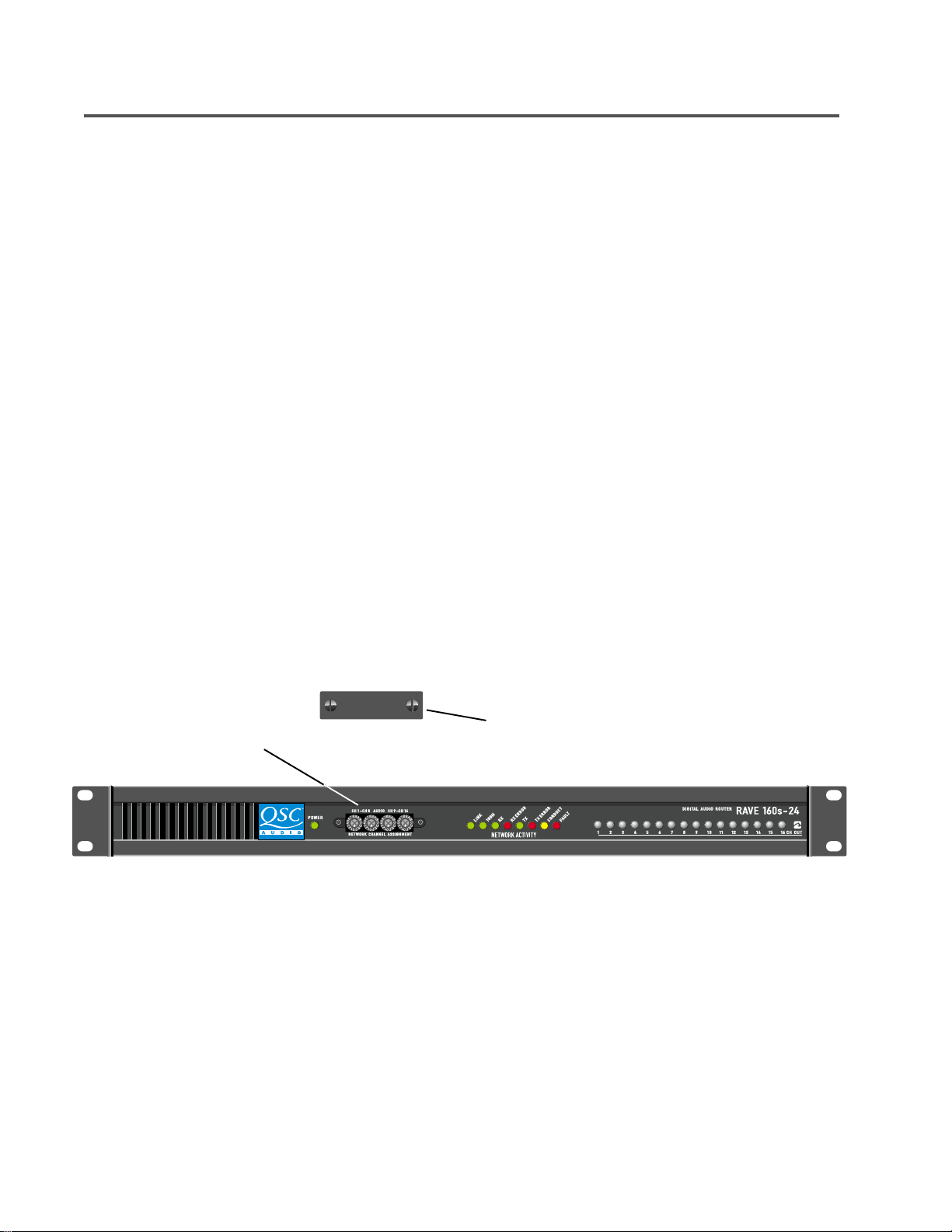
INTRODUCTION: Illustration of RAVE units
Front view of a RAVE 161s-24; other models are similar
Power LED
Rear view, from top:
RAVE 160s-24, RAVE 188s-24, RAVE 161s-24, RAVE 80s, RAVE 88s and RAVE 81s
Bundle assignment
selector switches
(behind cover)
Network status LEDs Audio signal level LEDs
Audio I/O section
Sync connections
Ethernet connection
RS-232 port
IEC connector (AC power)
and fuse holder
5

INTRODUCTION: Glossary
AES
3— A digital audio format specification approved by
the Audio Engineering Society and European Broad-
cast Union for inter-device conveyance of a dual-
channel (stereo) digital audio signal. Also called
AES/EBU. This specification is periodically revised
and amendments are published by the AES.
Bundle—The basic network transmission unit under Cobra-
Net. Up to 8 audio channels may be carried in a
bundle. Each bundle is assigned a unique number
and its value denotes the distribution type, either
multicast or unicast, between RAVE devices. A
bundle can be thought of as a virtual cable between
two or more RAVE devices, which transports mul-
tiple audio channels. Bundle numbers can be as-
signed to the RAVE via its front-panel interface or
through an SNMP supporting browser or related ap-
plication.
Channel
—A single digital audio signal. Audio channels on
CobraNet have a 48 kHz sampling rate and may
be of 16, 20 or 24-bit resolution. Up to 8 audio
channels may be carried in a bundle.
Latency
—The time interval from when an event occurs and
when it is perceived. In digital audio routing, this is
typically the time required to convert an analog in-
put to a digital signal, transmit that signal over the
network, receive it and convert it back to analog for
the end listening device. Latency is dependant upon
every device in the signal chain that adds any time
delay to the delivery of the audio.
Management Interface
be thought of as the software and front panel con-
trols that determine how the RAVE will operate. The
MI is the means for control and monitoring of
CobraNet parameters within the RAVE unit. Two
main management methods are supported by
CobraNet; the host management interface (HMI)
and SNMP. RAVE supports SNMP and its front panel
switches for control. A RAVE unit can use its front-
panel thumbwheel switches to access most con-
figuration parameters for stand-alone mode. The
front-panel interface will satisfy most configuration
requirements. All of RAVE’s configuration param-
eters are accessible using SNMP.
—The management interface (MI) can
6
Conductor
—The CobraNet device on the network which sup-
plies the master clock and permissions list. A con-
ductor arbitration procedure insures that there is
one and only one conductor per network at any time.
Crossover cabl
and receive wire pairs swapped at one end. Cross-
over cables permit a direct connection of two nodes
without a repeater or switch in between. A cross-
over cable can also be used for cascading repeat-
ers or switches that don’t have an available uplink
port.
e—An Ethernet patch cable with the transmit
MI Variable Set
— The MI variable set is the group of param-
eters that can be controlled by the MI.
Multicast Bundle
many routing of audio on the network. Ethernet
multicast addressing is used to deliver a multicast
bundle. Because a multicast bundle consumes band-
width network-wide (within the same broadcast do-
main), use of this delivery service must be rationed
on a switched network. By design, all bundles on a
repeater network are of the multicast type.
—A multicast bundle supports a one-to-

Introduction: Glossary (continued)
Repeater
Simple Network Management Protocol
Stand Alone Mode
Software Mode
—Network repeaters are commonly referred to as
Ethernet multi-port hubs. A data signal arriving in
any port is reproduced out all other ports on the
hub. A repeater hub does not buffer or interpret the
data passing through it. An Ethernet network is
typically wired in a star configuration and the
repeater hub is at the center. Repeaters are half-
duplex by design and all RAVEs attached to a
repeater share the same broadcast domain. 64
audio channels is the maximum capacity on a LAN
configured with network repeaters. Repeater
networks with RAVE require the use of Class II
devices that are 100 Mbps only.
Note: CobraNet networks must consist of only network re-
peaters or only network switches. A mix of these de-
vices is not supported on the same LAN. This does
not apply to non-CobraNet™ traffic.
—SNMP is the network
industry’s standard for control and monitoring of net-
work devices. SNMP is a cross-platform, cross-net-
work protocol and may be used as the interface for
managed network switches and multi-protocol rout-
ers. CobraNet supports SNMP as one method for ac-
cessing its Management Interface.
— Stand alone mode is operating a RAVE
using the RAVE’s front and rear panel controls. All
available management interface variables are ac-
cessed using the front panel hexadecimal switches
when operating in stand alone mode. Also called hard-
ware mode. Redundancy and external Synch can be
setup via SNMP independent of the front panel switch
positions.
— Software mode is operating a RAVE using
the SNMP software only. All available management
interface variables are accessed through the network
connection using a PC and the proper software.
Switch
—A network switch examines incoming data and sends
it to the port or ports to which the data is addressed.
Networks that use switches realize higher overall
bandwidth capacity because data may be received
through multiple ports simultaneously without con-
flict. Switches are full-duplex devices. A network
that uses switches to connect network segments is
called a switched network. Because each switch
port has its own collision management and full use
of bandwidth, audio capacity may realistically reach
several hundred channels depending on the network
architecture. Additionally, switched networks may
support non-CobraNet packet types, allowing con-
trol and monitoring of the system devices
(QSControl, SNMP). Network switches range from
basic stand-alone models to more complex man-
agement and routing devices.
Note: CobraNet networks must consist of only network
repeaters or only network switches. A mix of these
devices is not supported on the same LAN. This does
not apply to non-CobraNet traffic.
Unicast Bundle
Uplink por
— Unicast bundles provide a single point-to-
point connection between two devices. Unicast
transmission is the preferred choice when operat-
ing on network switches. Data which is unicast is
addressed to a specific RAVE or other CobraNet
device. A network switch may examine the unicast
address field of the data and determine on which
port the addressed RAVE resides and direct the data
out only that port. Unicast bundles conserve band-
width network wide and reduce congestion at the
node.
t—A special port on a network repeater or switch
used for cascading or linking to another repeater or
switch.
7

Introduction: How It Works
Ethernet networks are used most often for data communica-
tions, such as with file or print sharing on an office LAN (Lo-
cal Area Network). A typical application might include a num-
ber of PCs or workstations, servers and shared printers all
connected to common Ethernet hardware. Messages (Ether-
net frames) are communicated between devices on the LAN
in a random and non-deterministic manor. Network response
to print messages or file access is usually noncritical so long
as the intended outcome occurs in a reasonable amount of
time. For example, when multiple users are attempting to
share a common printer at the same time, some users will
likely experience delays in output. Collisions or failed attempts
to access the network may also be acceptable so long as the
intended messages are retransmitted. Most often, a limited
amount of collisions are expected and are usually transpar-
ent to the user.
nection and/or an abundance of bandwidth dedicated to a
single device on each switch port. On network switches, RAVE
establishes a half-duplex link to a dedicated port. The 100
Mbps of bandwidth available at a switched port is more than
enough to support all of the typical communications require-
ments of RAVE while providing for an ample amount of con-
trol and monitoring through the MI via SNMP messages.
A network of CobraNet devices can be thought of as a syn-
chronized orchestra. The unit acting in the “conductor” role
provides the system clock and grants network permissions to
the “performer” units. Each RAVE has a local internal clock so
that any RAVE may arbitrate for the role of network “conduc-
tor”. RAVE devices may also be synchronized to an external
clock source, which is attached to a rear-panel BNC connec-
tor. External synchronization requires configuration setup
through the front-panel interface or via SNMP. The permis-
Audio networks are different because late arrival or failed
attempts to transmit audio messages are immediately per-
ceived by the listener. Therefore, audio network transmission
must be error free with low latency and delivery must be pre-
cisely defined. To do this, RAVE incorporates the CobraNet
protocol. CobraNet is the industry’s most reliable audio deliv-
ery mechanism. CobraNet provides low latency, determinis-
tic delivery of audio over Ethernet on either network repeat-
ers or switches. Collisions are prevented on shared media
links, such as repeater hubs, by CobraNet’s proprietary “order
persistent” media access scheme. On dedicated media links,
such as with network switches, collisions are prevented due
to separate transmit and receive paths in a full-duplex con-
sions list is a message sent with the system clock that allow
individual units access to the network and reserve bundle as-
signments.
RAVE routes audio in bundles that are populated with a de-
fault value of 8 channels per bundle. The actual number of
channels per bundle may be altered, from 0 to 8, from the
management interface using SNMP. Reducing channel count
reduces system bandwidth requirements. On the models sup-
porting CobraNet transmission (81/88/161/188) audio is
brought into the RAVE using the rear panel connectors.
8
Introduction: How It Works (continued)
In default mode, the signals from the first 8 audio channel in-
puts will be grouped together in a bundle whose “network iden-
tifier” number is specified from the front-panel hexadecimal
switches or through the management interface. The bundle will
then be sent over the network to the destination devices that
are configured, or set to receive the bundle. RAVE models sup-
porting CobraNet reception (80/88/160/188) can then receive
the bundle by setting their respective front-panel hexadecimal
switches (or MI variables) to the appropriate bundle number.
The received bundle is then separated into individual audio chan-
nels and forwarded to the first 8 audio outputs at the rear-panel
in either analog or digital format, depending upon which model
Rave is used.
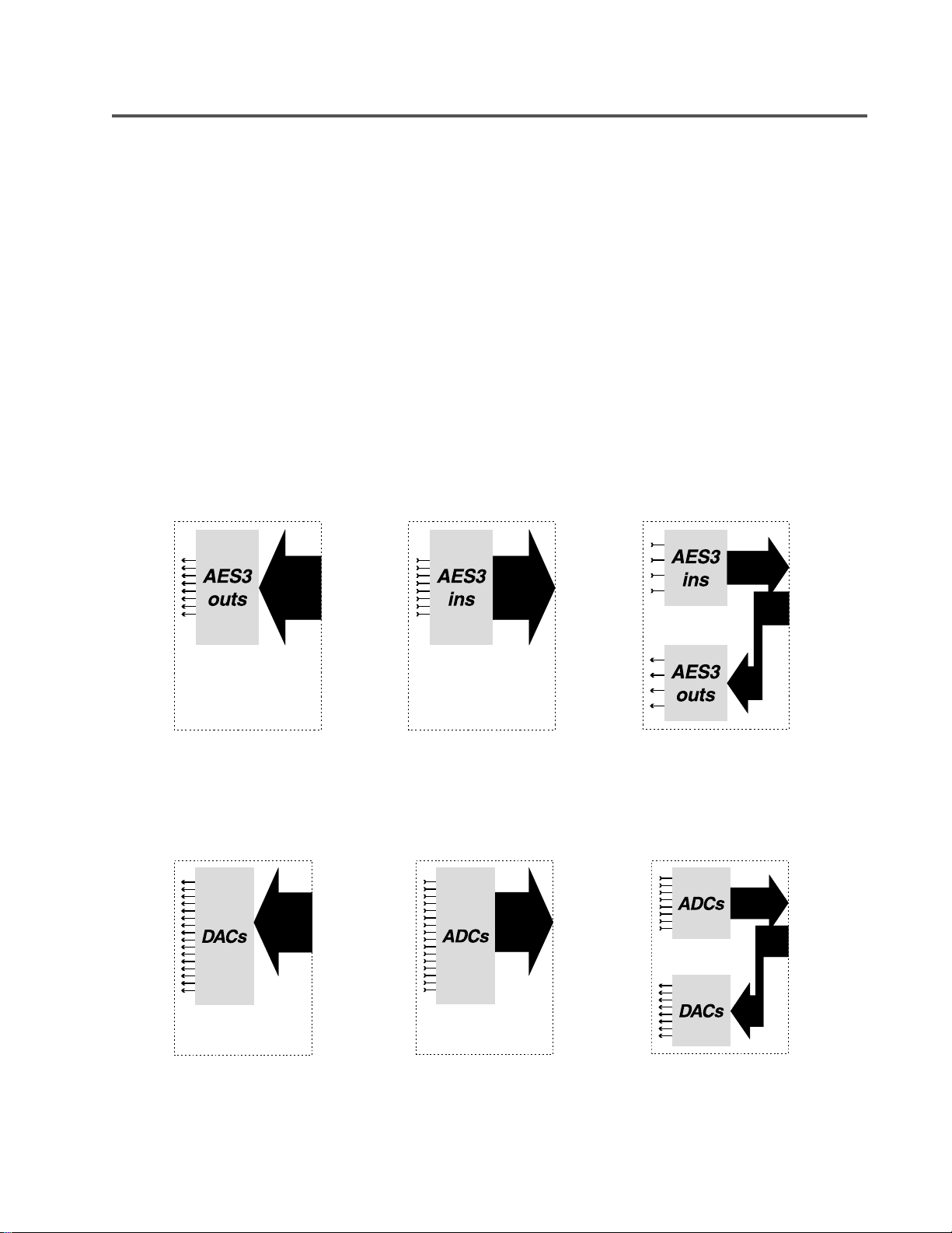
Signal flow for the six RAVE models are depicted below. The
wide black arrows indicate the bundle direction to or from the
network interface, while the thin arrows indicate individual audio
channels to or from RAVE’s rear-panel connectors.
RAVE 80s: 8 AES Outs
RAVE 160s-24: 16 analog
outs
RAVE 81s: 8 AES ins
RAVE 161s-24: 16 analog
ins
RAVE 88s: 4 AES ins + 4 AES
outs
RAVE 188s-24: 8 analog ins
+ 8 analog outs
9
Introduction: Channel Routing
Channel Routing
A RAVE network handles routing in bundles of up to eight audio
channels. Each bundle of audio transmitted on the network oc-
cupies a unique identifier, or number. In stand-alone mode, each
RAVE device handles two bundles—two sent, two received, or
one of each. For example, a RAVE 161, with 16 analog audio
inputs, supports two bundles for transmission over the network.
Therefore, the 161 requires two separate bundle number as-
signments to enable both groups of audio to be sent onto the
network. In default mode, one bundle comprises audio chan-
nels 1 through 8—the second bundle, channels 9 through 16.
You can always alter the number and order of audio channels
within each bundle via SNMP.
Similarly, a RAVE 80, with eight AES3 digital outputs, supports
network reception of two bundles (each AES3 output carries
two audio channels). With receivers, each bundle number need
not be unique. A receiver may “tune-in” to two specific bundles
signments may be the same. Whether the bundle assignments
on a receiver (or multiple receivers) can be duplicated is depen-
dent on whether the particular transmitters are setup for unicast
or multicast transmission. On network repeaters, all bundles
are multicast. On network switches, the value of the bundle
assignment determines the addressing of the transmission.
A RAVE device that both sends and receives, such as the RAVE
188 (eight analog inputs and 8 analog outputs) or RAVE 88 (4
AES3 inputs and 4 AES3 outputs), transmits one bundle and
can receive another. Note: in software mode, the RAVE 88 and
188 can support two bundles in each direction.
Behind a removable cover on the front panel of each RAVE unit
are four hexadecimal rotary switches. In stand-alone (hardware)
mode, these switches are used for selecting the assignments
for each of RAVE’s two bundles. In software mode, these
from two separate transmitters or both receiving bundle as-
Rotary Switches
Bundle Setup:
The two left-most switches set the assignment of the RAVE’s first bundle. The default mapping for the first bundle is:
RAVE 81/ 88/161 and 188- bundle 1 transmitted onto network from audio inputs 1 through 8
RAVE 80 and 160- bundle 1 received from network routes to audio outputs 1 through 8
The two right-most switches set the assignment of the device’s second bundle. The default mapping for the second bundle is:
RAVE 81 and 161- bundle 2 transmitted onto network from audio inputs 9 through 16
RAVE 88 and 188- bundle 2 received from network routes to audio outputs 1 through 8
switches are used to provide a network name for the RAVE.
Removable Cover- RAVE 160s-24 shown
10
RAVE 80 and 160- bundle 2 received from network routes to audio outputs 9 through 16
NOTE! Detailed instructions on setting network bundle assignments follow later in the Operation chapter.
Installation: Pre-Installation Level Setting (RAVE 160/161/188 only)
PRE-INSTALLATION PREPARATION: ANALOG AUDIO SIGNAL LEVELS (RAVE 160/161/188 ONLY)
The RAVE models supporting analog audio inputs and/or outputs may require signal level setup to
achieve optimum performance. Level setup must be configured before rack-mounting the units. The
digital AES3 (digital audio) models do not require any adjustment. Level adjustments are made by
configuring internal jumpers on the main circuit board. For access to these jumpers, you must first
remove the top cover of the RAVE unit as follows.
NOTE: If synchronizing to an AES3 (AES/EBU) source, see page 18 for AES3 jumper settings.
CAUTION: Detach the power cord
before removing the top cover.
Dangerous voltages within the
enclosure may be of sufficient
magnitude to constitute a risk of
electric shock to humans.
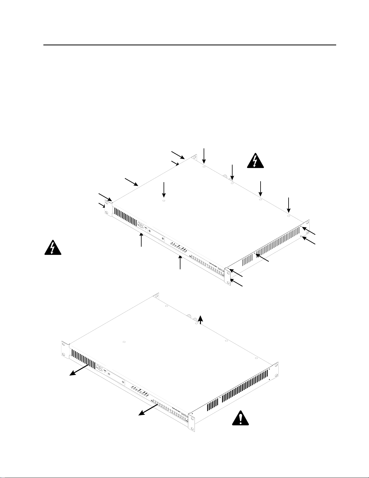
To remove cover, first detach the AC power cord,
then remove screws from top, bottom, and sides.
The arrows in this picture point to the 17 screw
locations.
Required tools: #2 Phillips screwdriver.
Then lift the rear edge of the top cover about ¼ inch, or 6
mm, and slide the cover forward about 2 inches, or 5 cm. Lift
the cover straight up to remove it from the chassis.
Reverse this procedure to reinstall the cover.
Be sure to take proper protective
measures, such as working on an
antistatic surface and wearing a grounding
wrist strap, before touching any circuitry
inside.
11
 Loading...