


Music & Paging Zone Mixer |
® |
|
|
||
User Manual |
|
|
|
|
|
|
|
|
MP-M80
MP-M40
TD-001578-01-A
*TD-001578-01*

EXPLANATION OF TERMS AND SYMBOLS
The term “WARNING!” indicates instructions regarding personal safety. If the instructions are not followed the result may be bodily injury or death.
The term “CAUTION!” indicates instructions regarding possible damage to physical equipment. If these instructions are not followed, it may result in damage to the equipment that may not be covered under the warranty.
The term “IMPORTANT!” indicates instructions or information that are vital to the successful completion of the procedure. The term "NOTE" is used to indicate additional useful information.
The intent of the lightning flash with arrowhead symbol in a triangle is to alert the user to the presence of un-insulated "dangerous" voltage within the product's enclosure that may be of sufficient magnitude to constitute a risk of electric shock to humans.
The intent of the exclamation point within an equilateral triangle is to alert the user to the presence of important safety, and operating and maintenance instructions in this manual.
IMPORTANT SAFETY INSTRUCTIONS
1.Read these instructions.
2.Keep these instructions.
3.Heed all warnings.
4.Follow all instructions.
5.Do not use this apparatus near water.
6.Clean only with a dry cloth.
7.Do not block any ventilation opening. Install in accordance with the manufacturer’s instructions.
8.Do not install near any heat sources such as radiators, heat registers, stoves, or other apparatus that produce heat.
9.To reduce the risk of electrical shock, the power cord shall be connected to a mains socket outlet with a protective earthing connection.
10.Do not defeat the safety purpose of the polarized or grounding-type plug. A polarized plug has two blades with one wider than the other. A grounding type plug has two blades and a third grounding prong. The wide blade or the third prong are provided for your safety. If the provided plug does not fit into your outlet, consult an electrician for replacement of the obsolete outlet.
11.Protect the power cord from being walked on or pinched particularly at plugs, convenience receptacles, and the point where they exit from the apparatus.
12.Only use attachments/accessories specified by the manufacturer.
13.Unplug this apparatus during lightning storms or when unused for long periods of time.
14.Refer all servicing to qualified service personnel. Servicing is required when the apparatus has been damaged in any way, such as powersupply cord or plug is damaged, liquid has been spilled or objects have fallen into the apparatus, the apparatus has been exposed to rain or moisture, does not operate normally, or has been dropped.
15.The appliance coupler, or the AC Mains plug, is the AC mains disconnect device and shall remain readily operable after installation. On units equipped with powerCon® connectors, the AC Mains disconnect device is the AC Mains plug only; do not use the appliance coupler.
16.Adhere to all applicable, local codes.
17.Consult a licensed, professional engineer when any doubt or questions arise regarding a physical equipment installation.
18.Do not use any aerosol spray, cleaner, disinfectant or fumigant on, near or into the apparatus. Clean only with a dry cloth.
19.Do not unplug the unit by pulling on the cord, use the plug.
20.Do not submerge the apparatus in water or liquids.
21.Keep ventilation opening free of dust or other matter.
TD-001578-01-A |
ii |

Maintenance and Repair
WARNING!: Advanced technology, e.g., the use of modern materials and powerful electronics, requires specially adapted maintenance and repair methods. To avoid a danger of subsequent damage to the apparatus, injuries to persons and/or the creation of additional safety hazards, all maintenance or repair work on the apparatus should be performed only by a QSC authorized service station or an authorized QSC International Distributor. QSC is not responsible for any injury, harm or related damages arising from any failure of the customer, owner or user of the apparatus to facilitate those repairs.
FCC Statement
NOTE: This equipment has been tested and found to comply with the limits for a Class B digital device, pursuant to Part 15 of the FCC Rules.
These limits are designed to provide reasonable protection against harmful interference in a residential installation. This equipment generates, uses and can radiate radio frequency energy and, if not installed and used in accordance with the instructions, may cause harmful interference to radio communications. However, there is no guarantee that interference will not occur in a particular installation. If this equipment does cause harmful interference to radio or television reception, which can be determined by turning the equipment off and on, the user is encouraged to try to correct the interference by one or more of the following measures:
•Reorient or relocate the receiving antenna.
•Increase the separation between the equipment and receiver.
•Connect the equipment into an outlet on a circuit different from that to which the receiver is connected.
•Consult the dealer or an experienced radio/TV technician for help.
RoHS STATEMENT
The QSC MP-M80 and MP-M40 Zone Mixers, are in compliance with European Directive 2011/65/EU – Restriction of Hazardous Substances (RoHS2).
The QSC MP-M80 and MP-M40 Zone Mixers are in compliance with “China RoHS” directives. The following chart is provided for product use in China and its territories:
|
|
|
|
QSC MP-M80 and MP-M40 Zone Mixers |
|
|
||
|
|
|
|
|
|
|
|
|
|
|
|
|
|
|
|
||
(Part Name) |
|
|
(Toxic or hazardous Substances and Elements) |
|
|
|||
|
|
|
|
|
|
|
|
|
|
(Pb) |
(Hg) |
|
(Cd) |
(Cr(vi)) |
|
(PBB) |
(PBDE) |
|
X |
O |
|
O |
O |
|
O |
O |
(PCB Assemblies) |
|
|
|
|
|
|
|
|
|
X |
O |
|
O |
O |
|
O |
O |
(Chassis Assemblies) |
|
|
|
|
|
|
|
|
O: SJ/T11363_2006
(O: Indicates that this toxic or hazardous substance contained in all of the homogeneous materials for this part is below the limit requirement in SJ/
T11363_2006.)
X: SJ/T11363_2006
(X: Indicates that this toxic or hazardous substance contained in at least one of the homogeneous materials used for this part is above the limit requirement in SJ/T11363_2006.)
Warranty
For a copy of the QSC Limited Warranty, visit the QSC website at www.qsc.com
Para una copia de la Garantía Limitada de QSC, visite el sitio web de QSC, en www.qsc.com
Pour obtenir une copie de la garantie limitée de QSC, visitez le site de QSC à www.qsc.com
TD-001578-01-A |
iii |
Besuchen Sie die Webseite von QSC (www.qsc.com) um eine Kopie der beschräenkte Garantie von QSC zu erhalten.
QSC QSC www.qsc.com
Для ознакомления с условиями ограниченной гарантии, посетите страницу компании QSC в интернете www.qsc.com
للحصول على نسخة من الضمان المحدود الخاص بـQSC، قم بزيارة الموقع الإلكتروني لشركة QSC للمنتجات الصوتية على www.qsc.com
TD-001578-01-A |
iv |

Table of Contents |
|
Music & Paging Zone Mixer Reference.. . . . . . . . . . . . . . . . . . . . . . . . . . . . . . . . . . . . 1 |
|
Getting Started.. . . . . . . . . . . . . . . . . . . . . . . . . . . . . . . . . . . . . . . . . . . . . . . . . . . . . . . . . . . . . . . . . . . . . . . . . . . |
. . . . . 1 |
System Requirements. . . . . . . . . . . . . . . . . . . . . . . . . . . . . . . . . . . . . . . . . . . . . . . . . . . . . . . . . . . . . . . . . . . . . . . . . . . . . . . . . . . . . . . . . . . . . |
1 |
MP Install. . . . . . . . . . . . . . . . . . . . . . . . . . . . . . . . . . . . . . . . . . . . . . . . . . . . . . . . . . . . . . . . . . . . . . . . . . . . . . . . . . . . . . . . . . . . . . . . . . . . . . . . . |
1 |
MP Manage. . . . . . . . . . . . . . . . . . . . . . . . . . . . . . . . . . . . . . . . . . . . . . . . . . . . . . . . . . . . . . . . . . . . . . . . . . . . . . . . . . . . . . . . . . . . . . . . . . . . . . . |
1 |
MP-MFC Controllers.. . . . . . . . . . . . . . . . . . . . . . . . . . . . . . . . . . . . . . . . . . . . . . . . . . . . . . . . . . . . . . . . . . . . . . . . . . . . . . . . . . . . . . . |
. . . . . . . 1 |
MP-M Hardware.. . . . . . . . . . . . . . . . . . . . . . . . . . . . . . . . . . . . . . . . . . . . . . . |
. . . . . . . .2 |
Front Panel.. . . . . . . . . . . . . . . . . . . . . . . . . . . . . . . . . . . . . . . . . . . . . . . . . . . . . . . . . . . . . . . . . . . . . . . . . . . . . . . . . . . . . . . . . . . . |
. . . . . . . . . . . 2 |
Rear Panel. . . . . . . . . . . . . . . . . . . . . . . . . . . . . . . . . . . . . . . . . . . . . . . . . . . . . . . . . . . . . . . . . . . . . . . . . . . . . . . . . . . . . . . . . . . . . . . . . . . . . . . . |
2 |
Specifications. . . . . . . . . . . . . . . . . . . . . . . . . . . . . . . . . . . . . . . . . . . . . . . . . . . . . . . . . . . . . . . . . . . . . . . . . . . . . . . . . . . . . . . . . . . . . . . . . . . . . |
3 |
MP Install .. . . . . . . . . . . . . . . . . . . . . . . . . . . . . . . . . . . . . . . . . . . . . . . . . . . . . |
. . . . . . . .4 |
Control Panel.. . . . . . . . . . . . . . . . . . . . . . . . . . . . . . . . . . . . . . . . . . . . . . . . . . . . . . . . . . . . . . . . . . . . . . . |
. . . . . . . . . . 4 |
Input Channels.. . . . . . . . . . . . . . . . . . . . . . . . . . . . . . . . . . . . . . . . . . . . . . . . . . . . . . . . . . . . . . . . . . . . . . . . . . . . . . . . |
5 |
Input Channel − Block Diagrams.................................................................................... |
5 |
Mic/Line and Auto-Mixer.. . . . . . . . . . . . . . . . . . . . . . . . . . . . . . . . . . . . . . . . . . . . . . . . . . . . . . . . . . . . . . . . . . . . . . . . . . . . . . . . . . |
. . . . . . . . . . . . . . .5 |
Line, USB, Music on Hold, Cue, Wireless Paging.. . . . . . . . . . . . . . . . . . . . . . . . . . . . . . . . . . . . . . . . . . . . . . . . . . . . . . . . . . . . . . . . |
. . . . . . . . . . . . 5 |
Input Channels – Home Screen .. . . . . . . . . . . . . . . . . . . . . . . . . . . . . . . . . . . . . . . . . . . . . . . . . . . . . . . . . . . . . . . . . . . . . . . |
. . . . . . . . . . . . .6 |
Input Channel – Navigation & Master Controls...................................................................... |
7 |
Input Channel – Setup. . . . . . . . . . . . . . . . . . . . . . . . . . . . . . . . . . . . . . . . . . . . . . . . . . . . . . . . . . . . . . . . . . . . . . . . . . . . . . . . . . . . . . . . . . . . . |
8 |
Input Channel – Overview. . . . . . . . . . . . . . . . . . . . . . . . . . . . . . . . . . . . . . . . . . . . . . . . . . . . . . . . . . . . . . . . . . . . . . . . . . . . . . . . . . . . . . . . . . |
9 |
Input Channel – Presets.. . . . . . . . . . . . . . . . . . . . . . . . . . . . . . . . . . . . . . . . . . . . . . . . . . . . . . . . . . . . . . . . . . . . . . . . . . . . . . . . . . . . . . . . . . |
10 |
Factory Presets .. . . . . . . . . . . . . . . . . . . . . . . . . . . . . . . . . . . . . . . . . . . . . . . . . . . . . . . . . . . . . . . . . . . . . . . . . . . . . . . . . . . . . . . . . . . |
. . . . . . . . . . . . . 10 |
User Presets.. . . . . . . . . . . . . . . . . . . . . . . . . . . . . . . . . . . . . . . . . . . . . . . . . . . . . . . . . . . . . . . . . . . . . . . . . . . . . . . . . . . . . . . . . . . . . . |
. . . . . . . . . . . . . 11 |
Input Channel – PEQ.............................................................................................. |
12 |
Input Channel – Dynamics.. . . . . . . . . . . . . . . . . . . . . . . . . . . . . . . . . . . . . . . . . . . . . . . . . . . . . . . . . . . . . . . . . . . . . . . . . . . . |
. . . . . . . . . . . . 13 |
Compressor.. . . . . . . . . . . . . . . . . . . . . . . . . . . . . . . . . . . . . . . . . . . . . . . . . . . . . . . . . . . . . . . . . . . . . . . . . . . . . . . . . . . . . . . . . . . . . . . . . . . . . |
. . . . . . . 13 |
Automatic Gain Control (AGC).. . . . . . . . . . . . . . . . . . . . . . . . . . . . . . . . . . . . . . . . . . . . . . . . . . . . . . . . . . . . . . . . . . . . . . . . . . . . . . |
. . . . . . . . . . . . . 14 |
Input Channel – Gate.. . . . . . . . . . . . . . . . . . . . . . . . . . . . . . . . . . . . . . . . . . . . . . . . . . . . . . . . . . . . . . . . . . . . . . . . . . . . . . . . . . . . . |
. . . . . . . . 15 |
Input Channel – USB Player Setup .. . . . . . . . . . . . . . . . . . . . . . . . . . . . . . . . . . . . . . . . . . . . . . . . . . . . . . . . . . . . . . . . . . . . |
. . . . . . . . . . . . 16 |
Input Channel – USB Player Overview.. . . . . . . . . . . . . . . . . . . . . . . . . . . . . . . . . . . . . . . . . . . . . . . . . . . . . . . . . . . . . . . . . |
. . . . . . . . . . . . 17 |
Input Channel – USB Player.. . . . . . . . . . . . . . . . . . . . . . . . . . . . . . . . . . . . . . . . . . . . . . . . . . . . . . . . . . . . . . . . . . . . . . . . . . . . . . . . . . . . . . |
18 |
Input Channel – USB Player PEQ.. . . . . . . . . . . . . . . . . . . . . . . . . . . . . . . . . . . . . . . . . . . . . . . . . . . . . . . . . . . . . . . . . . . . . . |
. . . . . . . . . . . . 19 |
Input Channel – USB Dynamics Automatic Gain Control (AGC).. . . . . . . . . . . . . . . . . . . . . . . . . . . . . . . . . . . . . . . . . . . . . . . . |
. . . . . 20 |
TD-001578-01-A |
v |
Output Zones.. . . . . . . . . . . . . . . . . . . . . . . . . . . . . . . . . . . . . . . . . . . . . . . . . . . . . . . . . . . . . . . . . . . . . . . . . . . . . . . . 21
Output Zone – Block Diagrams.................................................................................... |
21 |
Mono Zone.. . . . . . . . . . . . . . . . . . . . . . . . . . . . . . . . . . . . . . . . . . . . . . . . . . . . . . . . . . . . . . . . . . . . . . . . . . . . . . . . . . . . . . . . . . . . . . . . . . . . . . . . . . . . |
. 21 |
Stereo (Linked) Zone.. . . . . . . . . . . . . . . . . . . . . . . . . . . . . . . . . . . . . . . . . . . . . . . . . . . . . . . . . . . . . . . . . . . . . . . . . . . . . . . . . . . . . . . . . . . . . . . . . . . |
. 21 |
Output Zone – Home Screen..................................................................................... |
22 |
Output Zone – Navigation & Master Controls. . . . . . . . . . . . . . . . . . . . . . . . . . . . . . . . . . . . . . . . . . . . . . . . . . . . . . . . . . . . . . . . . . . . . |
23 |
Output Zone – Setup / Delay. . . . . . . . . . . . . . . . . . . . . . . . . . . . . . . . . . . . . . . . . . . . . . . . . . . . . . . . . . . . . . . . . . . . . . . . . . . . . . . . . . . . . |
24 |
Output Zone – Music on Hold.. . . . . . . . . . . . . . . . . . . . . . . . . . . . . . . . . . . . . . . . . . . . . . . . . . . . . . . . . . . . . . . . . . . . . . . . . . . . . . . . . . . . |
25 |
Output Zone – Overview. . . . . . . . . . . . . . . . . . . . . . . . . . . . . . . . . . . . . . . . . . . . . . . . . . . . . . . . . . . . . . . . . . . . . . . . . . . . . . . . . . . . . . . . . |
26 |
Output Zone – Sources. . . . . . . . . . . . . . . . . . . . . . . . . . . . . . . . . . . . . . . . . . . . . . . . . . . . . . . . . . . . . . . . . . . . . . . . . . . . . . . . . . . . . . . . . . |
27 |
Output Zone – Presets .. . . . . . . . . . . . . . . . . . . . . . . . . . . . . . . . . . . . . . . . . . . . . . . . . . . . . . . . . . . . . . . . . . . . . . . . . . . . . . . . . . . . . . . . . |
28 |
Factory Loudspeaker Library .. . . . . . . . . . . . . . . . . . . . . . . . . . . . . . . . . . . . . . . . . . . . . . . . . . . . . . . . . . . . . . . . . . . . . . . . . . . . . . . . . . . . . . . . . . . |
28 |
User Presets.......................................................................................................... |
29 |
Filters & PEQ.. . . . . . . . . . . . . . . . . . . . . . . . . . . . . . . . . . . . . . . . . . . . . . . . . . . . . . . . . . . . . . . . . . . . . . . . . . . . . . . . . . . . . . . . . . . . . . . . . . . . . . . . . . |
30 |
Output Zone – Graphic Equalizer (GEQ). . . . . . . . . . . . . . . . . . . . . . . . . . . . . . . . . . . . . . . . . . . . . . . . . . . . . . . . . . . . . . . . . . . . . . . . . . . . |
31 |
Output Zone – Anti-Feedback. . . . . . . . . . . . . . . . . . . . . . . . . . . . . . . . . . . . . . . . . . . . . . . . . . . . . . . . . . . . . . . . . . . . . . . . . . . . . . . . . . . . |
32 |
Output Zone – Loudness......................................................................................... |
33 |
Output Zone – Limiter. . . . . . . . . . . . . . . . . . . . . . . . . . . . . . . . . . . . . . . . . . . . . . . . . . . . . . . . . . . . . . . . . . . . . . . . . . . . . . . . . . . . . . . . . . . |
34 |
Mixer.. . . . . . . . . . . . . . . . . . . . . . . . . . . . . . . . . . . . . . . . . . . . . . . . . . . . . . . . . . . . . . . . . . . . . . . . . . . . . . . . . . . . . . . |
35 |
Mixer Main – Block Diagram.. . . . . . . . . . . . . . . . . . . . . . . . . . . . . . . . . . . . . . . . . . . . . . . . . . . . . . . . . . . . . . . . . . . . . . . . . . . . . . . . . . . . . |
35 |
Mixer Main – Home Screen.. . . . . . . . . . . . . . . . . . . . . . . . . . . . . . . . . . . . . . . . . . . . . . . . . . . . . . . . . . . . . . . . . . . . . . . . . . . . . . . . . . . . . . |
35 |
Mixer Main – PEQ.. . . . . . . . . . . . . . . . . . . . . . . . . . . . . . . . . . . . . . . . . . . . . . . . . . . . . . . . . . . . . . . . . . . . . . . . . . . . . . . . . . . . . . . . . . . . . . . |
36 |
Mixer – FX Channel.. . . . . . . . . . . . . . . . . . . . . . . . . . . . . . . . . . . . . . . . . . . . . . . . . . . . . . . . . . . . . . . . . . . . . . . . . . . |
37 |
Mixer – FX Effect.. . . . . . . . . . . . . . . . . . . . . . . . . . . . . . . . . . . . . . . . . . . . . . . . . . . . . . . . . . . . . . . . . . . . . . . . . . . . . . . . . . . . . . . . . . . . . . . |
37 |
Mixer – FX Presets.............................................................................................. |
37 |
Mixer – FX Shelf EQ. . . . . . . . . . . . . . . . . . . . . . . . . . . . . . . . . . . . . . . . . . . . . . . . . . . . . . . . . . . . . . . . . . . . . . . . . . . . . . . . . . . . . . . . . . . . . |
38 |
Setup Wizard.. . . . . . . . . . . . . . . . . . . . . . . . . . . . . . . . . . . . . . . . . . . . . . . . . . . . . . . . . . . . . . . . . . . . . . . . . . . . . . . . |
39 |
Menu .. . . . . . . . . . . . . . . . . . . . . . . . . . . . . . . . . . . . . . . . . . . . . . . . . . . . . . . . . . . . . . . . . . . . . . . . . . . . . . . . . . . . . . . |
40 |
Menu – Home Screen.. . . . . . . . . . . . . . . . . . . . . . . . . . . . . . . . . . . . . . . . . . . . . . . . . . . . . . . . . . . . . . . . . . . . . . . . . . . . . . . . . . . . . . . . . . . |
40 |
Menu – Configurations.. . . . . . . . . . . . . . . . . . . . . . . . . . . . . . . . . . . . . . . . . . . . . . . . . . . . . . . . . . . . . . . . . . . . . . . . . . . . . . . . . . . . . . . . . . |
.41 |
Menu – Scenes .. . . . . . . . . . . . . . . . . . . . . . . . . . . . . . . . . . . . . . . . . . . . . . . . . . . . . . . . . . . . . . . . . . . . . . . . . . . . . . . . . . . . . . . . . . . . . . . . . |
42 |
Menu – Scheduling.. . . . . . . . . . . . . . . . . . . . . . . . . . . . . . . . . . . . . . . . . . . . . . . . . . . . . . . . . . . . . . . . . . . . . . . . . . . . . . . . . . . . . . . . . . . . . . |
43 |
Menu – Controllers .. . . . . . . . . . . . . . . . . . . . . . . . . . . . . . . . . . . . . . . . . . . . . . . . . . . . . . . . . . . . . . . . . . . . . . . . . . . . . . . . . . . . . . . . . . . . . |
44 |
Menu – Smartphone.. . . . . . . . . . . . . . . . . . . . . . . . . . . . . . . . . . . . . . . . . . . . . . . . . . . . . . . . . . . . . . . . . . . . . . . . . . . . . . . . . . . . . . . . . . . . |
45 |
Menu – GPI Setup. . . . . . . . . . . . . . . . . . . . . . . . . . . . . . . . . . . . . . . . . . . . . . . . . . . . . . . . . . . . . . . . . . . . . . . . . . . . . . . . . . . . . . . . . . . . . . . |
46 |
Menu – Report. . . . . . . . . . . . . . . . . . . . . . . . . . . . . . . . . . . . . . . . . . . . . . . . . . . . . . . . . . . . . . . . . . . . . . . . . . . . . . . . . . . . . . . . . . . . . . . . . . |
47 |
Menu – System Test .. . . . . . . . . . . . . . . . . . . . . . . . . . . . . . . . . . . . . . . . . . . . . . . . . . . . . . . . . . . . . . . . . . . . . . . . . . . . . . . . . . . . . . . . . . . . |
48 |
TD-001578-01-A |
vi |
Menu – Network.. . . . . . . . . . . . . . . . . . . . . . . . . . . . . . . . . . . . . . . . . . . . . . . . . . . . . . . . . . . . . . . . . . . . . . . . . . . . . . . . . . . . . . . . . . . . . . . . |
49 |
Menu – Wired Network Setup: Auto IP Address .. . . . . . . . . . . . . . . . . . . . . . . . . . . . . . . . . . . . . . . . . . . . . . . . . . . . . . . . . . . . . . . . . . . . . . |
. . . 49 |
Menu – Wireless Network Setup: Create New Network.. . . . . . . . . . . . . . . . . . . . . . . . . . . . . . . . . . . . . . . . . . . . . . . . . . . . . . . . . . . . . . . . . . |
50 |
Menu – Wireless Network Setup: Connect to Existing Network........................................................... |
50 |
Menu – Wired Network Setup: Static IP Address.. . . . . . . . . . . . . . . . . . . . . . . . . . . . . . . . . . . . . . . . . . . . . . . . . . . . . . . . . . . . . . . . . . . . . |
. . . . 51 |
Menu – Security.. . . . . . . . . . . . . . . . . . . . . . . . . . . . . . . . . . . . . . . . . . . . . . . . . . . . . . . . . . . . . . . . . . . . . . . . . . . . . . . . . . . . . . . . . . . . . . |
. . . 51 |
Staff Access Management.. . . . . . . . . . . . . . . . . . . . . . . . . . . . . . . . . . . . . . . . . . . . . . . . . . . . . . . . . . . . . . . . . . . . . . . . . . . . . . . . . . . . . . . . . . . . . . |
51 |
Reset Passwords.. . . . . . . . . . . . . . . . . . . . . . . . . . . . . . . . . . . . . . . . . . . . . . . . . . . . . . . . . . . . . . . . . . . . . . . . . . . . . . . . . . . . . . . . . . . . . . . . . . . |
. . . . 51 |
Menu – Settings.. . . . . . . . . . . . . . . . . . . . . . . . . . . . . . . . . . . . . . . . . . . . . . . . . . . . . . . . . . . . . . . . . . . . . . . . . . . . . . . . . . . . . . . . . . . . . . |
. . 52 |
Multi-Function Controller.. . . . . . . . . . . . . . . . . . . . . . . . . . . . . . . . . . . . . . . . . . . . . |
53 |
Setup (Refer to Menu – Controllers.).. . . . . . . . . . . . . . . . . . . . . . . . . . . . . . . . . . . . . . . . |
. 53 |
Operation....................................................................................................... |
53 |
MP Manage. . . . . . . . . . . . . . . . . . . . . . . . . . . . . . . . . . . . . . . . . . . . . . . . . . . . . . . . . . |
54 |
MP Manage – Home Screen.. . . . . . . . . . . . . . . . . . . . . . . . . . . . . . . . . . . . . . . . . . . . . . . . . . . . . . . . . . . . . . . . . . . . . . . . . . . . . . . . . . . |
. . 54 |
MP Manage – Security.. . . . . . . . . . . . . . . . . . . . . . . . . . . . . . . . . . . . . . . . . . . . . . . . . . . . . . . . . . . . . . . . . . . . . . . . . . . . . . . . . . . . . . . . |
. . 55 |
Log in as Manager .. . . . . . . . . . . . . . . . . . . . . . . . . . . . . . . . . . . . . . . . . . . . . . . . . . . . . . . . . . . . . . . . . . . . . . . . . . . . . . . . . . . . . . . . . . . . . . . . . . |
. . . 55 |
Add a New User.. .. .. .. .. .. .. .. .. .. .. .. .. .. .. .. .. .. .. .. .. .. .. .. .. .. .. .. .. .. .. .. .. .. .. .. .. .. .. .. .. .. .. .. .. .. .. .. .. .. .. .. .. .. .. .. .. .. .. .. .. .. .. .. .. .. .. .. .. .. .. .. .. .. .. .. .. .. .. .. .. .. .. .. .. .. .. .. .. .. .. .. .. .. .. .. .. .. .. .. .. |
.. .. .. 55 |
MP Manage – Zone Overview.. . . . . . . . . . . . . . . . . . . . . . . . . . . . . . . . . . . . . . . . . . . . . . . . . . . . . . . . . . . . . . . . . . . . . . . . . . . . . . . . . . |
. . 56 |
MP Manage – Zone Edit.. . . . . . . . . . . . . . . . . . . . . . . . . . . . . . . . . . . . . . . . . . . . . . . . . . . . . . . . . . . . . . . . . . . . . . . . . . . . . . . . . . . . . . . |
. . 56 |
MP Manage – Scheduler......................................................................................... |
57 |
MP Manage – Scenes.. . . . . . . . . . . . . . . . . . . . . . . . . . . . . . . . . . . . . . . . . . . . . . . . . . . . . . . . . . . . . . . . . . . . . . . . . . . . . . . . . . . . . . . . . |
. . 58 |
MP Manage – Player.. . . . . . . . . . . . . . . . . . . . . . . . . . . . . . . . . . . . . . . . . . . . . . . . . . . . . . . . . . . . . . . . . . . . . . . . . . . . . . . . . . . . . . . . . . |
. . 58 |
MP Manage – Mixer. . . . . . . . . . . . . . . . . . . . . . . . . . . . . . . . . . . . . . . . . . . . . . . . . . . . . . . . . . . . . . . . . . . . . . . . . . . . . . . . . . . . . . . . . . . . . |
59 |
MP Manage – Paging. . . . . . . . . . . . . . . . . . . . . . . . . . . . . . . . . . . . . . . . . . . . . . . . . . . . . . . . . . . . . . . . . . . . . . . . . . . . . . . . . . . . . . . . . . . . |
60 |
MP-M Dimensions .. . . . . . . . . . . . . . . . . . . . . . . . . . . . . . . . . . . . . . . . . . . . . . . . . . . .61
MP-M Block Diagrams.. . . . . . . . . . . . . . . . . . . . . . . . . . . . . . . . . . . . . . . . . . . . . . . . 64
Mic/Line Input Channels & Auto Mixer. . . . . . . . . . . . . . . . . . . . . . . . . . . . . . . . . . . . . . . . . . . . . . . . . . . . . . . . . . |
64 |
Line Inputs, USB Inputs, Music on Hold, Cue, Wireless Paging .. . . . . . . . . . . . . . . . . . . . . . . . . . . . . . . . . . . . . |
65 |
Mono Zone Output .. . . . . . . . . . . . . . . . . . . . . . . . . . . . . . . . . . . . . . . . . . . . . . . . . . . . . . . . . . . . . . . . . . . . . . . . . . . |
66 |
Mono Output Zones .. . . . . . . . . . . . . . . . . . . . . . . . . . . . . . . . . . . . . . . . . . . . . . . . . . . . . . . . . . . . . . . . . . . . . . . . . . |
67 |
Stereo (Linked) Zone Outputs.. . . . . . . . . . . . . . . . . . . . . . . . . . . . . . . . . . . . . . . . . . . . . . . . . . . . . . . . . . . . . . . . . |
68 |
Mixer.. . . . . . . . . . . . . . . . . . . . . . . . . . . . . . . . . . . . . . . . . . . . . . . . . . . . . . . . . . . . . . . . . . . . . . . . . . . . . . . . . . . . . . . |
69 |
TD-001578-01-A |
vii |
Music & Paging Zone Mixer Reference
The information provided in this section gives you a detailed description of the screens and controls for the Music & Paging Zone Mixer and the Music & Paging Zone Mixer remote apps.
Getting Started
The QSC MP-M music and paging mixers are fixed architecture mixer/processors offering unprecedented capabilities combined with ease of configuration and operation. The products are intended for retail and hospitality applications in which high-quality audio from various sources is routed to multiple zones. Live mixing functions are also supported for applications requiring reinforcement of entertainment, presentations or conferences.
System Requirements
The MP-M Apps support:
•Android – 5.0 or later
•iOS – 8.0 or later
•macOS – 10.9 or later
•Windows – 10
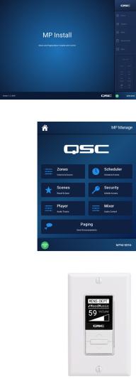
MP Install
This app (for iOS / Android tablets, Windows and Mac OS) allows system designers and installers to quickly and easily design and configure systems for MP-M Series mixers. This wireless control features an intuitive Workflow Wizard to navigate through room tuning and speed commissioning.
MP Manage
For wireless control, the MP Manage app (for iOS / Andorid tablets and smartphones) provides end users day-to- day operation of basic system functions including zone level, source selection, scene recall, scheduling, and mixer control. It also offer a unique store-and-forward zone paging functionality to the MP-M Series mixer.
MP-MFC Controllers
The MP-MFC Controllers are intuitive wall mount controls to enable customizable system adjustments for the MP-M Series music and paging mixer. They provide multi-zone source selection, scene selection and volume control. Designers can configure these peripherals to provide end users with as much or as little control over the system as needed
TD-001578-01-A |
1 |
MP-M Hardware
Front Panel
NOTE!: MP-M80 is shown.
1.CUE – Headphones, 3.5 mm, stereo
2.USB – USB-A (rear panel – 1, front panel – 1), fi rmware & confi guration uploads, USB Wi-Fi
3. |
STATUS – |
Action |
|
Appearance |
Defi nition |
|
|
|
|||
|
|
|
|
|
|
|
|
Off |
|
|
OK |
|
|
|
|
|
|
|
|
On |
|
|
Booting |
|
|
|
|
|
|
|
|
Slow Blink |
Firmware Upgrade |
||
|
|
|
|
|
|
|
|
SOS Blink |
Upgrade Failure |
||
4. |
PO ER – |
|
|
|
|
|
|
On |
Off |
|
|
|
|
|
|
|
|
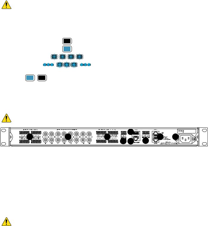
Rear Panel
NOTE!: MP-M80 is shown.
1 |
2 |
3 |
5 |
8 |
9 |
|
|||||
|
|
4 |
6 |
7 |
|
1.INPUTS (MIC/LINE) – Mic / Line Inputs, balanced, 12 V Phantom power, MP-M80 has 8 inputs, MP-M40 has 4 inputs, 6-pin Euroblock connectors.
2.INPUTS (MONO SUMMINN) – RCA Pairs, summed to mono, MP-M80 has 8 pairs, MP-M40 has 4 pairs.
3.OUTPUTS (LINE LEVEL) – Balanced, Line Level, MP-M80 has 8 line level outputs, MP-M40 has 4 line level outputs, 6-pin Euroblock connectors.
4.MUSIC ON HOLD – Transformer-balanced, 3-pin Euroblock connector
5.USB – USB-A (rear panel – 1, front panel – 1), fi rmware & confi guration uploads, USB Wi-Fi
6.Ethernet – RJ45 For connecting to a network, wired and/or wireless.
7.NPI – 2 Inputs, Euroblock
8.MFC – MP-MFC ports, up to 4 MFC’s per connection, 2 RJ45 connectors
9.AC Mains – power connection, 100-240 V, ~85 W, 50/60 Hz
CAUTIONG!: If AC power is removed, wait for 5 seconds before reapplying the AC power.
TD-001578-01-A |
2 |

Specifications
Model |
MP-M40 |
MP-M80 |
|
Inputs |
|
|
|
Total |
8 |
16 |
|
|
|
|
|
Mic/Line |
4 (Euroblock) |
8 (Euroblock) |
|
RCA |
4 (mono-summed RCA pairs) |
8 (mono-summed RCA pairs) |
|
|
|
|
|
Outputs |
|
|
|
Total |
6 |
10 |
|
Line |
4 (Euroblock, balanced) |
8 (Euroblock, balanced) |
|
|
|
|
|
Music-on-Hold |
1 (Euroblock, transformer balanced) |
1 (Euroblock, transformer balanced) |
|
|
|
|
|
Cue (phones) |
1 (3.5 mm, stereo) |
1 (3.5 mm, stereo) |
|
Audio |
|
|
|
Sampling frequency |
48 kHz |
|
|
|
|
|
|
Processing |
32-bit floating point |
|
|
THD |
<0.005%, +4 dBu and -2 dBr; 20 Hz-20 kHz, unity gain, any input to any output |
||
|
|
|
|
Frequency response |
20 Hz-20 kHz +/-0.5 dB, mic/line or line input to any line output |
|
|
|
|
|
|
Dynamic range |
>106 dB unweighted |
|
|
Crosstalk |
>90 dB typical, >80 dB max |
|
|
|
|
|
|
Gain (mic inputs) |
51 dB |
|
|
|
|
|
|
Maximum input level |
+24 dBu (mic/line inputs), +10dBV (line inputs) |
|
|
Maximum output level |
+21 dBu (line-level outputs), +10dBV (Music on Hold) |
|
|
|
|
|
|
Phantom power |
All microphone inputs (+12 volts) |
|
|
|
|
|
|
Latency |
2.3 msec |
|
|
Input Processing |
|
|
|
EQ |
4-band parametric EQ with high/low shelving option, variable 24 dB/octave HPF and LPF |
||
|
|
|
|
Dynamics |
Gate, choice of Auto Gain Control (AGC) or compressor |
|
|
Output Processing |
|
|
|
EQ |
1/3 octave GEQ |
|
|
|
|
|
|
Anti-feedback filters |
12-band variable notch filters |
|
|
Dynamics |
Comp/limiter, ducker, loudness |
|
|
|
|
|
|
Delay |
100 msec |
|
|
|
|
|
|
Loudspeaker tunings |
Factory: Intrinsic Correction™ voicing for QSC loudspeakers |
|
|
User: 6-band parametric EQ, HPF & LPF (Linkwitz-Riley or Butterworth; 12, 18 or 24 dB/octave) |
|||
|
|||
Control Accessories |
|
|
|
MP-MFC |
Optional wall controller |
|
|
|
|
||
MP Install |
For configuration/design functions (for iOS/Android tablets, Windows and Mac OS PCs), |
||
|
|
||
MP Manage |
For end user control functions (for iOS/Android tablets and smartphones) |
||
|
|
|
|
Other Connections |
|
|
|
Ethernet |
1 x RJ45 for connection to Wi-Fi router (user supplied) |
|
|
|
|
|
|
MP-MFC ports |
2 x RJ45 |
|
|
|
|
|
|
USB |
2 USB-A (firmware & configuration uploads, USB Wi-Fi) |
|
|
|
|
|
|
GPI |
2 inputs (Euroblock) |
|
|
Power requirements |
100-240VAC, 50-60 Hz, universal supply, IEC inlet |
|
|
|
|
|
|
Indicators |
Blue POWER LED, blue STATUS LED |
|
|
|
|
|
|
Dimensions (Net) |
1.75 in x 19 in x 14 in (4.5 cm X 48.3 cm X 35.6 cm) |
|
|
Weight |
|
|
|
Shipping |
11.0 lb (5.0 kg) |
|
|
|
|
|
|
Net |
7.0 lb (3.2 kg) |
|
|
Specifications are subject to change without notice.
TD-001578-01-A |
3 |
MP Install
MP Install is an app that runs on iOS, Android and Windows. It is intended for use by system designers and installers. See the Network section of this document for instructions on logging in to a new MP-M for the fi rst time.
Control Panel
The Control Panel (right side of screen) provides navigation to all mixer controls, indicators and functions.
Navigational Controls
1.Inputs – Opens a screen that displays icons representing the controls and processing blocks for input channels.
2.Outputs – Opens a screen that displays the icons representing the controls and processing blocks for output channels.
3.Mixer – Opens the MP-M built-in mixer screen.
4. Setup izard – Opens a screen that provides a checklist of setup tasks and links to areas of the mixer where the tasks are performed.
5.Menu – Opens a screen providing access to the setup functions for the system.
Operational Controls
6.Cue Level button – Opens the Cue Level pop-up.
7.Copy and Paste buttons – The MP-M has a powerful but simple copy and paste function. Copy and Paste is context sensitive so what you are looking at is what will be copied. Only “like” things can be copied and pasted from and to each other. For example, a PEQ cannot
be pasted to a GEQ. Some screens cannot be copied, for example the Inputs Home screen. In these cases a dialog displays saying “Copy not available here”.
8.Prev  &
&  Next buttons – Navigate to the next or previous channel.
9.Nudge up  & down
  buttons – Increases or decreases the value setting of the selected control.
10.Zero  button – Returns the selected control to its factory default value.
11.Fine  button – Decreases the amount of change that will be applied by the Nudge buttons.
12.Cue Level fader – Touch and drag to adjust the level of audio from the Cue output jack.
13.Cue Level Close button – Touch to close the Cue fader pop-up.
6
7
8
9
10
1
2
3
4
12
5
13
11
TD-001578-01-A |
4 |

Input Channels
Input Channels Block Diagrams
Touch Inputs
Mic/Line and Auto-Mixer
+12 V
|
Gain |
|
|
|
|
|
|
|
|
|
Level |
|
|
Mic Pre |
A/D |
Delay |
Polarity |
Low Cut |
High Cut |
Gate |
PEQ |
Store & |
Comp |
Gain |
Pan |
Mute |
To Mixer |
|
Φ |
|
|
|
|
Forward |
AGC |
|
|
|
|||
|
|
|
|
|
|
|
|
|
|
|
Mic/Line
Input 1
From GPI |
|
|
|
|
or Gate |
|
Mute |
|
To Outputs |
|
|
|
|
|
|
|
FX |
FX Send |
|
Automatic Microphone Mixer |
|
|
|
|
To Mixer |
|
|
|
|
|
|
|
Cue |
To Cue |
|
|
|
|
From |
|
|
|
Mic/Line |
Compare |
|
|
Input 1 |
|
|
|
|
|
|
|
From |
|
To |
|
Mic/Line |
Compare |
|
|
Input 2 |
Mic/Line |
|
|
Auto-Mixer |
|
||
|
Ch. 2 |
|
|
|
Algorithm |
|
|
From |
|
|
|
|
To |
|
|
Mic/Line |
Compare |
|
|
Input 3 |
Mic/Line |
|
|
|
|
||
|
|
Ch. 3 |
|
From |
|
To |
|
Mic/Line |
Compare |
|
|
Input 4 |
Mic/Line |
|
|
|
|
||
|
|
Ch. 4 |
|
|
MP-M40: 4 Channels |
|
|
|
MP-M80: 8 Channels |
|
|
Line, USB, Music on Hold, Cue, Wireless Paging
Line |
|
|
|
|
Input 1 |
|
|
|
|
Sum |
A/D |
Low Cut |
High Cut |
PEQ |
|
|
|
||
Line |
|
|
|
|
Input 1 & 2 |
|
|
|
|
Linked |
|
|
|
|
|
A/D |
Low Cut |
High Cut |
PEQ |
|
|
|
|
|
|
A/D |
|
|
|
USB Input |
|
Low Cut |
High Cut |
AGC |
|
|
|||
Music On Hold |
|
|
|
|
MOH Source |
|
|
|
Level |
Selection |
|
|
|
|
From Inputs |
|
|
|
|
Delay 
 Dynamics
Delay 
 Dynamics
PEQ
Level |
|
|
|
Gain |
Pan |
Mute |
To Mixer |
|
|
|
|
|
|
Mute |
To Outputs |
|
|
|
|
|
|
Cue |
To Cue |
|
|
|
|
Level |
|
|
|
Gain |
Balance |
Mute |
To Mixer |
|
|
|
|
|
|
Mute |
To |
|
|
Linked |
|
|
|
|
|
|
|
|
Outputs |
|
|
|
To |
|
|
|
Mono |
|
|
Cue |
Outputs |
|
|
To Cue |
|
|
|
|
|
|
Music |
DAC |
|
On |
|
|
Hold |
|
Cue |
To Cue |
|
|
From |
Low Cut |
High Cut |
AGC |
PEQ |
Mute |
|
|
Wi-Fi |
To Outputs |
||||||
|
|
|
|
|
|||
Wireless Paging |
|
|
|
|
|
|
|
|
Frequency |
|
|
|
Cue |
To Cue |
|
|
|
|
|
|
|||
|
|
|
|
|
|
||
|
Sine |
|
|
|
Noise Level |
|
|
Signal |
|
|
|
|
|
||
|
|
|
|
|
To |
||
Generator |
Noise |
|
|
|
|
||
|
|
|
|
Zones |
|
Cue |
|
|
From |
Gain |
DAC |
Phones |
Cue |
|
DAC |
|
|
|
TD-001578-01-A |
5 |

Input Channels – Home Screen
Touch Inputs
The Inputs home screen displays a high-level overview of the channels in a channel bank along with links to the various control groups, Setup, PEQ, Dynamics, and so on.
1. Channel Banks |
(MP-M80 Shown) – Select from |
|
|
|
1 |
|
|
|
|
|
|
|
|
|
|
||
channels |
2 |
3 |
|
4 |
5 |
6 |
7 |
8 |
• Mic/Line – Displays Mic/Line input processing |
3a |
3b |
3c |
|
|
|
|
|
blocks. |
|
|
|
|
|
|||
|
|
|
|
|
|
|
|
|
•RCA – Displays processing blocks for the monosummed RCA inputs.
•More – Displays processing blocks for the USB
|
Player and Wi-Fi paging. |
3d |
|
|
|
|
|
2. |
Setup – Touch to access Input Name, Channel |
|
|
|
Safe, Stereo Link, Reset and Delay. |
|
|
3. |
1 ManagersMic |
C M Overview – Touch to access Overview |
3e |
|
screen. The Inputs screen displays: |
||
|
|
||
a.Channel number
b.Name
c.Level meter
d.C – Cue status light color indicates the Cue is active, dark color indicates the Cue is inactive.
e.M – Mute status Red indicates the channel is muted, dark color indicates channel is not muted.
4.Type of Input – Mic/Line or Mono Summed
5. Presets – Touch to access the Presets screen to access recall, reset, save / save as, Factory and User presets, and more.
6. PEQ – Dark button indicates the PEQ is not engaged, light button indicates the PEQ is engaged. Touch the button to access the PEQ screen where all PEQ parameters and engaging / disengaging the PEQ can be accessed.
7. Dynamics – The Dynamics consists of a Compressor and an AGC. A dark button indicates the Compressor / AGC is not engaged, light button indicates the Dynamics are engaged. Touch the button to access the Dynamics screen where switching between the AGC or Compressor, and modifying all parameters and engaging / disengaging the Dynamics can be accomplished.
8. Nate – Dark button indicates the Gate is not engaged, light button indicates the Gate is engaged. Touch the button to access the Gate screen where you can modify all Gate parameters and engage / disengage the Gate.
TD-001578-01-A |
6 |
Input Channel − Navigation |
|
|
|
|
Inputs |
Touch an |
|
Touch a Channel |
|
|
|
|
|
|
|
|
|||
and Master Controls |
|
|
|
|
|
Input Bank |
|
Setup Button |
|
|
|
|
|
|
Mic/Line |
|
|
||
|
|
|
|
|
|
|
|
||
Input channels are the audio source for all Output Zones |
|
|
|
|
|
(RCA / More) |
|
|
|
|
|
|
|
|
|
|
|
||
and for the MP-M Internal Mixer. All controls on the input |
1 |
2 |
3 |
4 |
5 |
6 |
7 |
||
channels affect the Mixer and the Output Zones with the |
|||||||||
|
|
|
|
|
|
|
|
||
exception of the Fader, Pan and Auto-Mix which affect only |
|
|
|
|
|
|
8 |
||
the Mixer. When an Input Channel is selected the following |
|
|
|
|
|
|
9 |
||
controls and indicators are available |
|
|
|
|
|
|
|||
Input Channel Navigation Controls |
|
|
|
|
|
|
16 |
|
|
|
|
|
|
|
|
|
|
||
The icons at the top of the screen are used to navigate the |
|
|
|
|
|
|
10 |
|
|
channel processing blocks. Refer to the individual topics |
|
|
|
|
|
|
|
|
|
for details of the following: |
|
|
|
|
|
|
11 |
|
|
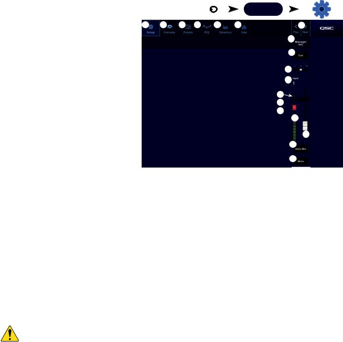
1.Setup – The Setup screen provides controls to change the channel name, input trim, and various other functions.
2.Overview – The Overview screen displays and provides controls for most of the parameters associated with a channel.
3.Presets – The Presets screen provides controls to recall, save, and manage presets.
12
13
14
15
17
18
4.PEQ – The Parametric EQ screen provides controls to adjust the parametric EQ for the channel.
5.Dynamics – The Dynamics screen provides the option to select the Compressor or AGC (Automatic Gain Control, and the controls to adjust either.
6.Nate – The Gate screen provides controls to setup and make adjustments to the Gate.
7.Prev / Next – Navigates to the next or previous channel. The buttons cycle through the Input, Line In, and FX channel, then loops back to Input 1.
Input Channel Master Controls
8.Channel Label – Displays the name as entered in the Setup screen’s Input Name fi eld.
9.Cue – Sends the pre-fader channel signal to the Cue headphone output.
10.Channel Type and Number – Displays the type of channel (Mic, Stereo, Playback, Record, FX) and its number. This cannot be changed.
11.N – Indicates that the Gate for the channel is engaged or not.
12.C – Indicates that the Dynamic processing (Compressor or AGC) for the channel in engaged or not.
13.P – Indicates that Phantom power for the channel is engaged or not.
14.Meter – Indicates the channel signal level. This meter is Pre-fader.
15.Mute – Mutes the channel going to the zones and to the MP-M internal mixer.
NOTE!: The MP-M includes an internal mixer. The following controls adjust the channel’s signal in the mixer only and have no effect on the channel signal that is sent to the zones.
16.Fader – Adjusts the level of the channel’s signal in the MP-M internal mixer.
17.Pan – Adjusts the Left/Right balance of the channel in the MP-M internal mixer.
18.Auto-Mix (microphone inputs only) – Applies the Auto-Mixer (see the Mixer Section topic) to the channel.
TD-001578-01-A |
7 |
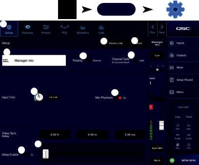
Input Channel − Setup
The setup screen includes a number of functions that are primarily “set once and forget”. Channel Setup is provided for all input channels.
1.Setup button – Selects the Setup screen
2.Stereo Link button – Links / unlinks adjacent channels for stereo operation. The odd numbered channel settings are copied to the even numbered channel. Pan settings are mirrored. Only odd/even linking is supported (1-2, 3-4, etc.). Even/odd linking (2-3, 4-5) is not available.
3.Reset button – Returns all Setup settings, for this channel, to default values.
4.Input Name fi eld – Displays the name of the channel. Touch to display a keyboard and rename the channel with a “friendly name”. Use only upper and lower case alpha characters.
5.Polarity switch – Inverts the polarity of the input signal.
6.Channel Safe During Scene Recall switch – When set to Safe, the channel will not be affected by a scene recall.
7.Input Trim knob – Adjusts the input sensitivity for the Mic/Line channels. Not available on the USB Player or Wifi
|
Inputs |
Touch an |
Touch a Channel |
|
Input Bank |
Setup Button |
|
|
|
||
|
|
Mic/Line |
|
|
|
(RCA / More) |
|
1 |
|
|
|
|
|
2 |
3 |
4 |
|
5 |
6 |
|
|
7 |
8 |
9
10
Paging.
8.Mic Phantom switch – Turns phantom power on or off for the channel (Mic/Line input channels only). (available on MP-M80 channels 1-8 and on MP-M40 channels 1-4)
9.Video Sync Delay slider – Video Sync Delay allows the audio to be delayed by up to 100 milliseconds. The delay value is also displayed in feet and meters. This feature is typically used to compensate for “lip fl ap” which occurs when the latency of a video signal is greater than that of the accompanying audio.
10.Delay Enable switch – Engages or disengages the Video Sync Delay.
TD-001578-01-A |
8 |
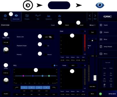
Input Channel − Overview
The Input Overview screen displays an at-a-glance view of the settings for the selected input. Most controls on this screen also appear on other input screens.
To copy all the settings for an input, touch the Copy button while this screen is displayed. To paste the settings to another input, navigate to the target input and touch Paste.
The following items are available on the Input Channel Overview screen.
1.Navigation icons – Touch an icon to navigate to the associated Input Channel processing block. (See topics for details.)
2.Preset button – Displays the currently active input preset. Touch the fi eld to navigate to the Presets processing block to recall or manage presets. This fi eld is not available on the USB Player or WiFi channels. (See topic for details.)
|
Touch |
Touch an |
Touch a Channel |
|
|
Inputs |
Input Bank |
Overview Button |
|
|
|
|
Mic/Line |
|
1 |
|
|
(RCA / More) |
|
|
|
|
|
|
|
|
|
2 |
3 |
4 |
|
|
5 |
8 |
|
|
|
||
|
|
|
6 |
|
|
|
|
7 |
|
9 |
|
10 |
11 |
|
3.Reset button – Touch to reset all Input Channel controls to the factory default setting.
4.Input Trim knob – Adjusts the input sensitivity for the Mic/Line channels. Not available on the USB Player or Wifi Paging.
5.Stereo Link button – Links adjacent, odd/even channels for stereo operation. Not available on the USB Player or WiFi channels.
6.Phantom Power switch – Turns phantom power on or off for the channel (Mic/Line input channels only). (available on MP-M80 channels 1-8 and on MP-M40 channels 1-4)
7.Polarity switch – Reverses the polarity for the channel signal. Available on Mic/Line input channels only.
8.Nate – Available controls on this screen are: In, Threshold, Attack, Release, Attenuation, and Hold. Select a control and use the Nudge buttons to change values. Not available on the USB Player or WiFi channels. (See topic for details.)
9.Delay knob and Enable button – Adjusts delay and enables / disables the delay. Not available on the USB Player or WiFi channels.
10.PEQ – Available controls on this screen are: In, HPF, LPF, Gain, and Frequency. Select a control and use the Nudge buttons to change values. (See topic for details.)
11.Comp and ANC –
a.Available controls for the Compressor on this screen are: In, Thresh, Attack, Release, Ratio, and Gain. Select a control and use the Nudge buttons to change values. (See topic for details.)
b.Available controls for the AGC on this screen are: In, Max Target, Min Target, Max Gain, Threshold, and Release. Select a control and use the Nudge buttons to change values. (See topic for details.)
TD-001578-01-A |
9 |
stored with the preset but may be omitted from a preset |
|
7 |
|
|
|
recall by setting the Recall Omits switches to omit them. |
|
|
|
|
|
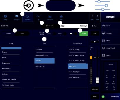
Input Channel − Presets |
Inputs |
Touch an Input Bank |
|||
The MP-M includes presets for speech and musical |
|
|
Mic/Line |
||
instruments. The musical instrument presets are intended |
|
|
(RCA / More) |
||
for applications in which the Mixer section is used for |
1 |
|
|
|
|
reinforcement of live entertainment. |
|
|
|
|
|
An Input Channel Preset consists of settings for the |
|
2 |
3 |
|
|
channel EQ, dynamics and gate that can be saved and |
4 |
5 |
6 |
||
recalled. The channel name and level settings are also |
|||||
|
|
|
|
12 V |
|
Factory Presets
1.Presets button – Displays the Presets screen.
2.Preset Info button – Touch to display a pop-up message with details about the current Preset. Touch OK on the pop-up to close.
3.Current Preset fi eld – Displays the name of the currently active preset.
4.Factory / User switch – Selects between the internal factory presets or user presets. Refer to the User Presets topic for details.
5.Recall Omits – Allows selected parameters to be unaffected by a preset recall. The parameters that can
be selected are: Levels, Name, 12V phantom power. The parameter is selected for omission when the switch is “on”.
6.Recall button – Touch to recall the preset selected in the Selection windows.
7.Selection windows – These windows (Input, Type, and Preset Name) are used to select a preset for recall.
Touch a Channel
Presets Button
TD-001578-01-A |
10 |
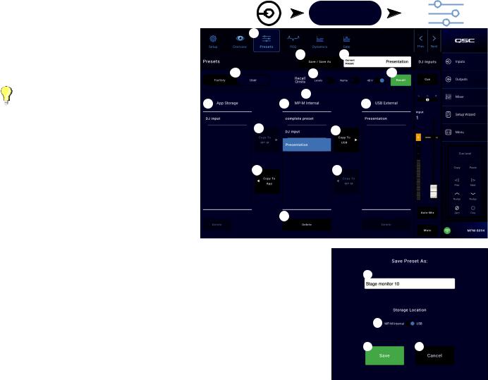
User Presets
The User Preset screen is where custom user tunings and presets are stored and managed.
Inputs |
Touch an Input Bank |
Touch a Channel |
|
Presets Button |
|||
|
|
Mic/Line
(RCA / More)
1. Presets button – Displays the Presets screen. |
1 |
|
|
|
2. Save / Save as button – Touch to displays a pop-up |
|
|
||
|
|
|
||
message with details about the current Preset. Touch |
|
2 |
3 |
|
OK on the pop-up to close. |
4 |
5 |
6 |
|
|
||||
TIP!: If a Factory Preset is recalled, it |
|
7 |
|
|
can then be saved as a user preset. This |
|
|
||
8 |
9 |
10 |
||
can be used as a start on which to build |
||||
|
|
|
||
custom presets. |
11 |
|
12 |
|
|
|
a.Save Preset As fi eld – touch the fi eld to access a keyboard and enter a different name for the preset
or, leave the name as it is, and continue to the |
13 |
14 |
|
next step. |
|||
|
|
||
b. Storage Location switch – Select either |
|
|
|
MP-M Internal (on the mixer), or USB attached to |
|
|
|
the mixer. |
|
15 |
c.Save button – Touch the button to save the preset in the selected location.
d.Cancel button – Touch the button to exit the dialog without saving the preset.
3. Current Preset fi eld – Displays the name of the currently active preset. |
1a |
4.Factory / User switch – Selects between the internal factory presets or user presets. User presets may be stored and recalled to and from the MP-M internal memory or an attached USB storage device.
5.Recall Omits – Allows selected parameters to be unaffected by a preset recall. The parameters that can be selected are: Levels, Name, 48V Phantom power. The parameter is selected when the switch is “on”.
1b
1c |
1d |
6.Recall button – Touch to recall the preset selected in either the MP-M Internal, or the USB External list.
7.Selection windows – These windows (App Storage, MP-M Internal, and USB External) are used to select a preset for recall and to copy presets from one location to another.
8.App Storage list - Displays any user presets stored in the internal memory of the device being used to control the MP-M. When this panel is selected, the Copy to MP-M button will copy the preset to MP-M internal memory. You cannot Recall a preset from App Storage. To Recall, save the preset to MP-M Internal, then Recall.
9.MP-M Internal list – Displays any user presets stored in the MP-M internal memory. When this panel is selected, the selected Preset can be copied to either the App Storage or USB External. In addition, the Preset can be recalled, then be saved or saved as a different preset
10.USB External list – Displays any user presets stored on a connected USB device. When this panel is selected, the selected Preset can be copied to the MP-M Internal storage. In addition, the Preset can be recalled, then can be saved or saved as a different preset.
One item in the App Storage list, MP-M Internal list, or the USB External list must be selected for the following controls to be available.
11.Copy To MP-M button – Touch to copy a selected preset from the App Storage to the MP-M Internal storage.
12.Copy to USB button – Touch to copy a selected preset from the MP-M Internal storage to the USB storage.
13.Copy To App button– Touch to copy a selected preset from the MP-M Internal storage to the App Storage.
14.Copy to MP-M button– Touch to copy a selected preset from the USB External storage to the MP-M Internal storage.
15.Delete button – Deletes the selected preset.
TD-001578-01-A |
11 |
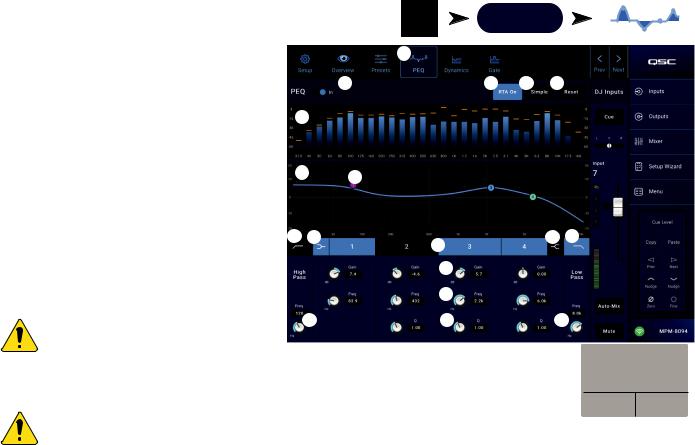
Input Channel − PEQ
This screen controls and displays the settings for the Input Channel parametric equalization.
The PEQ is a 4-band, fully parametric EQ that includes variable HPF (High Pass Filter) & LPF (Low Pass Filter).
•The HPF is variable with a range of 20 Hz to 2,000 Hz. It passes frequencies above the setting while cutting those below.
•The LPF is variable with a range of 1 kHz to 20 kHz. It passes frequencies below the setting while cutting those above.
•Bands 1 and 4 may be confi gured as shelving fi lters.
1.PEQ tab – Selects the EQ screen.
2.PEQ Out/In – Engages / disengages the equalizer.
3.RTA On – Engages / disengages the a real time analyzer that displays the tonal balance of the channel’s signal including peak hold indicators.
NOTE!: Only one RTA may be running on the system at a time. Touch the RTA button. If another device is using the RTA, the message to the right displays.
|
Inputs |
Touch an |
Touch a Channel |
|
Input Bank |
PEQ Button |
|
|
|
||
|
|
Mic/Line |
|
|
(RCA / More) |
|
|
|
1 |
|
|
2 |
3 |
4 |
5 |
6
7 8
9 |
10 |
11 |
10 |
9 |
|
|
|
|
|
|
|
12 |
|
|
|
|
13 |
|
|
|
15 |
14 |
15 |
|
The RTA is currently being used by [device name]. Do you want to assign it instead to this device?
Yes No
NOTE!: When the RTA is off, the Parametric EQ graph expands to use the entire graph area.
4.Simple button – Hides the Frequency, and Q controls for all bands and low and high cut fi lters. Changing to Simple mode does not affect existing settings.
5.Reset button – Sets all the PEQ controls to their factory default position.
6.RTA display – Displays the amplitude of the channel signal in 1/3 octave bands. Peak hold indicators are displayed for each band.
•RTA graph vertical scale – Represents audio level from -60 dB to -5 dB.
•RTA graph horizontal scale – Represents frequency from 31.5 Hz to 16 kHz.
7.Parametric EQ graph – A graphic representation of the equalization curve based on the PEQ settings. The trace dims to indicate that the PEQ is Out (disengaged).
•EQ graph vertical scale – Represents audio level from -20 dB to +20 dB.
•EQ graph horizontal scale – Represents frequency from 20 Hz to 20 kHz.
8.EQ handles – Touch, hold, and drag to change the Frequency and Gain of the associated PEQ band. The frequency band button must be engaged to see the handles.
9.High Pass and Low Pass buttons – Engages / disengages the HPF and LPF (described above).
10.Low Shelf and High Shelf fi lter buttons – Changes EQ Band 1 and Band 4 from parametric fi lters to shelving fi lters. When a shelf fi lter is
engaged, the Q control is not available. The low shelving fi lter raises or lowers a range of frequencies below the set frequency. The high shelving fi lter raises or lowers a range of frequencies above the set frequency.
11.Frequency Bands 1, 2, 3, and 4 buttons – Engages / disengages the associated parametric EQ band. Each band is fully parametric with a frequency range of 20 Hz to 20 kHz.
12.Nain control knob and readout – Adjusts the gain at the frequency setting of the associated EQ band. Range of -15 dB to +15 dB.
13.Freq control knob (Frequency bands 1 – 4) – Sets the center frequency of the associated EQ band. If the Shelving fi lter is engaged, the Freq control sets the knee frequency of the shelf fi lter.
14.Q knob – Adjusts the Q of the associated EQ band. When the Shelf Filter is selected, the Q control is hidden. In addition, Q can be adjusted by “pinching”.
15.Freq control knob (Low and High Cut) – Sets the frequency of the low and/or high cut fi lter as measured from a point 3 dB below 0 or unity.
TD-001578-01-A |
12 |
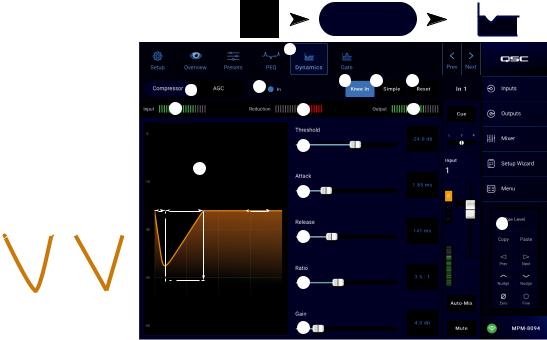
Input Channel − Dynamics |
|
(Compressor / ANC) |
Inputs |
|
The Input Channel Dynamics processing block may
be confi gured as either a Compressor or an Automatic
Gain Control (AGC).
1
Compressor
The Compressor controls the dynamic range of a signal above a set Threshold.
1.Dynamics button – Selects the Compressor / AGC screen.
2.Compressor / ANC button – Selects either Compressor or AGC.
|
2 |
3 |
|
|
|
7 |
|
8 |
|
|
11 |
|
|
10 |
3. In switch – Engages and disengages the |
B C |
D |
12 |
|
Compressor or AGC processor. |
|
A |
||
|
|
|
|
|
4. Knee In button |
|
|
|
13 |
– Determines how |
|
|
|
|
|
|
|
|
|
abruptly or gradually the |
Knee |
|
|
|
compressor transitions |
E |
|
14 |
|
in and out of gain |
In |
Out |
|
|
reduction as the threshold |
|
|
||
is crossed. |
|
|
|
15 |
5.Simple button – Turns Simple mode on and off. When on, it hides all controls except:
•Compressor / AGC
•Comp In
•Simple
•Reset
•Compression (Threshold)
All other controls remain at the value set prior to engaging the Simple mode button.
Touch an Input Bank |
Touch a Channel |
|
Dynamics Button |
||
|
Mic/Line
(RCA / More)
4 |
5 |
6 |
|
|
9 |
16
6.Reset button – Sets all the Compressor and AGC controls, for this channel, to their factory default position.
7.Input meter – Displays the RMS input signal level
8.Reduction meter – The red display indicates how much the signal is being reduced by the compressor. This meter displays a signal regardless of whether the In button is engaged or not.
9.Output meter – Output level after any applied compression
10.Compressor graph – Vertical scale from 0 dB to -60 dB; horizontal measurement is time. When engaged, the trace displays.
•Threshold (A) – The level at which compression begins.
•Attack time (B to E) – The time it takes for the compression to reach its maximum compression after the input exceeds the threshold level.
•Ratio (A to E) – The amount of compression applied to the signal.
•Release time (C to D) – The time it takes for the compressed signal to rise to the threshold level once the input level no longer exceeds the threshold.
11.Threshold slider – Sets the point at which the compressor begins to reduce signal level.
12.Attack slider – Adjusts how quickly the compressor reacts to a signal that exceeds the threshold.
13.Release slider – Adjusts how quickly the compressor stops compressing when signal falls below threshold.
14.Ratio slider – Sets the ratio of input level change to output level change when the signal exceeds the threshold.
15.Nain slider – Adjusts the overall output gain to makeup any loss after the signal is compressed.
16.Compressor in/out indicator – When the Compressor (or AGC) is In, an orange “C” displays on the channel controls strip.
TD-001578-01-A |
13 |
Automatic Gain Control (AGC)
The Automatic Gain Control is used to compensate for variations in the audio level of the source material.
Touch |
Touch an Input Bank |
Touch a Channel |
|
Inputs |
Dynamics Button |
||
|
Mic/Line
(RCA / More)
1. |
Dynamics button – Selects the Compressor / AGC |
|
|
|
1 |
|
|
screen. |
|
|
|
|
|
|
|
|
|
|
|
|
2. |
Compressor / ANC button – Selects either |
|
2 |
3 |
|
4 |
|
Compressor or AGC. |
|
|
|||
|
|
|
|
|
|
|
3. |
In switch – Engages and disengages the |
|
5 |
6 |
|
7 |
|
AGC processor. |
8 |
8a |
|
|
|
4. |
Reset button – Sets all the Compressor and |
|
|
9 |
|
|
|
|
|
|
|||
|
AGC controls, for this channel, to their factory |
|
8b |
|
|
|
|
default position. |
|
|
|
|
|
|
|
|
|
|
14 |
|
5. |
Input meter – Displays the RMS input signal level |
|
|
|
10 |
|
|
|
|
|
|||
|
|
|
|
|
||
6. |
Reduction meter – Indicates how much the signal |
|
|
|
|
|
|
level has been altered by the AGC. The center (0 |
|
8c |
|
11 |
|
|
dB) indicates that no gain change is being applied. |
|
|
|
||
|
|
|
|
|
|
|
|
Rightward movement of the meter indicates that |
|
|
|
|
|
|
gain is being applied. Leftward movement indicates |
|
|
|
12 |
|
|
attenuation (reduction) of the signal level. |
|
|
|
|
|
7. |
Output meter – Indicates the output signal level |
|
|
|
|
|
|
after AGC has been applied. |
|
|
|
13 |
|
8.ANC graph – Vertical scale from 0 dB to -60 dB. When the AGC is engaged, the trace is displayed.
a.Max Target – Indicates the maximum level that the AGC will maintain.
b.Min Target – Indicates the minimum level that the AGC will attempt to maintain.
c.Threshold – Indicates the level at which the AGC becomes active / inactive.
9.Max Target slider – Sets the maximum level that the AGC will maintain.
10.Min Target slider – Sets the minimum level that the AGC will attempt to maintain.
11.Max Nain slider – Sets a limit on the amount of gain the AGC will apply regardless of the target settings.
12.Threshold slider – Sets the level at which the AGC becomes active / inactive. Signals that fall below the threshold level are assumed to be intentional silence and the AGC will apply no additional gain.
13.Release slider – Adjusts how long the AGC holds its gain change after the input signal level changes.
14.ANC in/out indicator – When the AGC (or Compressor) is In, an orange “C” displays on the channel controls strip.
NOTE!: The AGC should not be used on microphone inputs if there is any possibility of feedback.
If the source device lacks an output volume control, use the input channel gain control to simulate low and high level playback. Use the Cue output and headphones to listen to the results of the AGC.
To Adjust the AGC
1.Using program material that is slightly greater in level than the desired maximum signal level, adjust the Max Target slider until the Reduction indicates a slight amount of gain reduction by moving to the left of center.
2.Using program material that is slightly lower in level than the desired minimum signal level, adjust the Min Target slider until the Reduction Meter indicates a slight amount of gain addition by moving to the right of center.
3.If some low-level passages of the program material are being boosted excessively, use the Max Gain control to decrease the maximum gain the AGC applies.
4.With no program material playing, adjust the Threshold so that the Reduction Meter shows no additional gain being applied. This adjustment prevents the AGC from applying full gain to residual noise from the sources when no signal is present.
TD-001578-01-A |
14 |
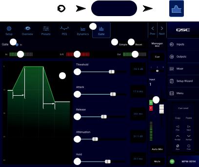
Input Channel − Nate
The Gate passes audio above a set Threshold, and attenuates audio below the Threshold. In addition, the Gate is used as part of the Store & Forward paging function.
1.Nate button – Selects the Gate Screen.
2.Nate In switch – Engages or disengages the Gate.
3.Simple button – Turns Simple mode on and off. Hides all controls except:
•Gate In button
•Simple button
•Reset button
•Gating slider
4.Reset button – Sets all the Gate controls to their factory default position.
5.In meter – RMS input level
6.N.R. meter – Gain Reduction – indicates how much the signal is being reduced by the Gate.
7.Out meter – Output level
8.Nate graph – When the Gate is engaged, the trace turns green. Horizontal axis is time, vertical axis
is level.
|
|
Inputs |
|
Touch an Input Bank |
Touch a Channel |
|||||
|
|
|
Nate Button |
|||||||
|
|
|
|
|
|
|
||||
|
|
|
|
|
Mic/Line |
|
|
|
|
|
|
|
|
|
|
|
|
|
|
|
|
|
|
|
|
|
(RCA / More) |
|
|
|
|
|
|
|
|
|
|
|
|
|
|
|
|
|
|
|
|
|
1 |
|
|
|
|
|
|
|
|
|
|
|
|
|
|
|
|
2 |
|
|
|
|
3 |
4 |
|
|
|
|
|
5 |
|
|
6 |
|
7 |
|
|
|
|
|
|
8 |
9 |
|
|
|
|
|
|
|
|
|
|
|
|
|
|
|
|
||
A |
|
|
|
|
|
|
|
|
|
|
|
|
|
E |
10 |
|
|
14 |
|
|
|
A |
B |
|
|
|
|
|
|
|
||
|
|
|
|
|
|
|
|
|||
|
C |
D |
11 |
|
|
|
|
|
|
|
|
|
|
|
|
|
|
|
|
|
|
12
13
•Threshold (A)
•Attack time (A-B)
•Release time (C-D)
•Attenuation Level (E).
9.Threshold slider – Sets the point at which the Gate allows audio to pass.
10.Attack slider – Adjusts how quickly the gate reacts to a signal that exceeds the threshold.
11.Release slider – Adjusts how quickly the Gate attenuates the audio when signal falls below threshold.
12.Attenuation slider – Sets the amount of attenuation applied to the output when the signal is below the Threshold.
13.Hold slider – Sets the minimum time the Gate stays open once it is opened, and the length of time the Gate stays open after the input level drops below the Threshold.
14.Compressor in/out indicator – When the Compressor (or AGC) is In, an orange “C” displays on the channel controls strip.
TD-001578-01-A |
15 |
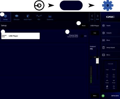
Input Channel − USB Player Setup
The setup screen includes a number of functions that are primarily “set once and forget”. Channel Setup is provided for all input channels.
1.Setup button – Selects the Setup screen
2.Reset button – Returns all Setup settings, for this channel, to default values.
3.Input Name fi eld – Displays the name of the channel. Touch to display a keyboard and rename the channel with a “friendly name”. Use only upper and lower case alpha characters.
4.Channel Safe During Scene Recall switch – When set to Safe, the channel will not be affected by a scene recall.
Inputs |
Touch More Input |
Touch Setup |
|
Bank |
|||
|
|
More
1
2
3 |
4 |
TD-001578-01-A |
16 |
 Loading...