

Page 1
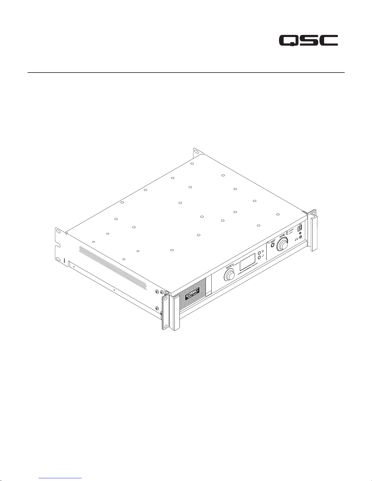
Digital Processor Monitor
User Manual
DPM 100 | DPM 100H | DPM 300 | DPM 300H
®
TD-000515-01-D
*TD-000515-01*
Page 2

Introduction
QSC’s DPM is a powerful solution for today’s D-Cinema audio systems. From server to speakers, the DPM offers a complete set of tools to facilitate all
the signal processing, audio distribution, monitoring and automation control services required in a modern D-Cinema sound system.
The DPM builds on the legacy of QSC’s DCM and DCP products to provide all signal processing and monitoring functions for Digital Cinema in a
single integrated system. Designed to be used with QSC’s Digital Cinema Amplifiers (DCA) and featuring advanced Intrinsic Correction™ settings for
QSC’s Digital Cinema Speakers (DCS), the DPM optimizes loudspeaker performance while simplifying cinema sound system wiring and configuration.
The DPM 100 and DPM 100H are configurable for passive and bi-amp operation. The DPM 300 and 300H are also configurable for tri-amp and
quad-amp operation. Though optimized to receive audio content directly from a D-Cinema server, the DPM is also compatible with all analog cinema
processor formats and features an 8 channel analog input for integration with 35 mm audio systems.
The DPM is more than an audio processor. Whether designing a system for a single auditorium or designing a large multiplex, the DPM offers the
flexibility in configuration, networking, audio distribution and advanced management services to get the job done.
Features
• Digital inputs accept AES-3 audio from a D-Cinema server or other digital audio source
• Analog inputs accept audio from film processors or other 8 channel analog audio sources
• Additional analog inputs accommodate non-sync and Mic/Line sources
• Additional digital inputs include HDMI® (DPM 100H and DPM 300H only) and SPDIF
• The DPM 100H and DPM 300H include Dolby Audio™ (featuring Dolby Digital Plus™) and DTS-HD® decoding.
• QSC Intrinsic Correction settings for optimal performance of QSC cinema speakers
• Master volume and full cinema processor EQ on all channels
• Booth monitor with front panel control for easy operation
• Passive or 2-way crossovers for three screen channels (all models)
• 3-way or 4-way crossovers for three screen channels (DPM 300 and 300H only)
• Compatible with all existing QSC DCA amplifiers
• Bypass mode – routes audio around failed components to ensure that the show will go on.
• Control and monitoring via Ethernet including full SNMP support
• Continued development of software and firmware will add new capabilities via easy updates
Package Contents
1. DPM 100, DPM 100H, DPM 300 or
DPM 300H
Rack Mounting
The DPM is designed to be mounted in a standard 19" (480 mm) equipment rack and requires 2 vertical rack spaces. Mount the DPM using four
screws and washers. Tighten securely. The DPM comes with rear rack support ears. Make sure that the rear mounting points are securely fastened to
rear rack rails or rack side walls.
Warranty
For a copy of the QSC Limited Warranty, visit the QSC website at www.qsc.com
Para una copia de la Garantía Limitada de QSC, visite el sitio web de QSC, en www.qsc.com
Pour obtenir une copie de la garantie limitée de QSC, visitez le site de QSC à www.qsc.com
Eine Kopie der beschränkten QSC-Garantie finden Sie auf der QSC Webseite unter www.qsc.com.
如果您想要QSC有限保修的複印本,请造访QSC音频产品的网站www.qsc.com
Для получения копии ограниченной гарантии QSC посетите веб-сайт QSC Audio Products, расположенный по адресу www.qsc.com.
www.qsc.com QSC
TD-000515-01-D
2. User Guide TD-000515
3. IEC power cord
2
4. Euro style connector plug kit
5. Limited Warranty TD-000453-01
QSC
Page 3
Controls and Connectors
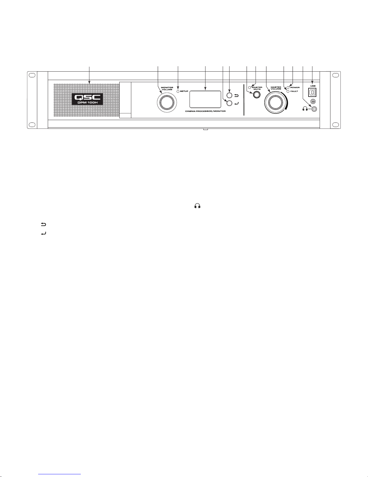
Front Panel
1
1. Full-range monitor speaker
2. MONITOR VOLUME – Function depends on operating mode
a. Monitor mode – controls level to DPM front panel loudspeaker
b. Setup mode – provides parameter adjustment
3. SETUP mode indicator LED – illuminates yellow when Monitor
Volume knob is in setup mode
4. 128 x 64 bit LCD monochrome display
5. Navigation
a. – press to navigate to a higher level menu
b. – press to navigate to a lower level menu or edit a parameter
2 3 4 5a 5b 6 7 8 9 10 11
12
— Figure 1 —
6. MASTER MUTE button – Mutes all outputs when engaged
7. MASTER MUTE LED – illuminates red when Mute is engaged
8. MASTER VOLUME knob – global level control for all audio outputs
9. FA U LT LED – illuminates yellow when load faults or system errors
are detected
10. POWER LED – illuminates green when AC power is applied
11. – Headphone jack (3.5 mm TRS) for attaching external powered
monitor speaker or headphones (automatically mutes speaker)
12. USB Type B port for DPM configuration and management.
TD-000515-01-D
3
Page 4
Rear Panel Features
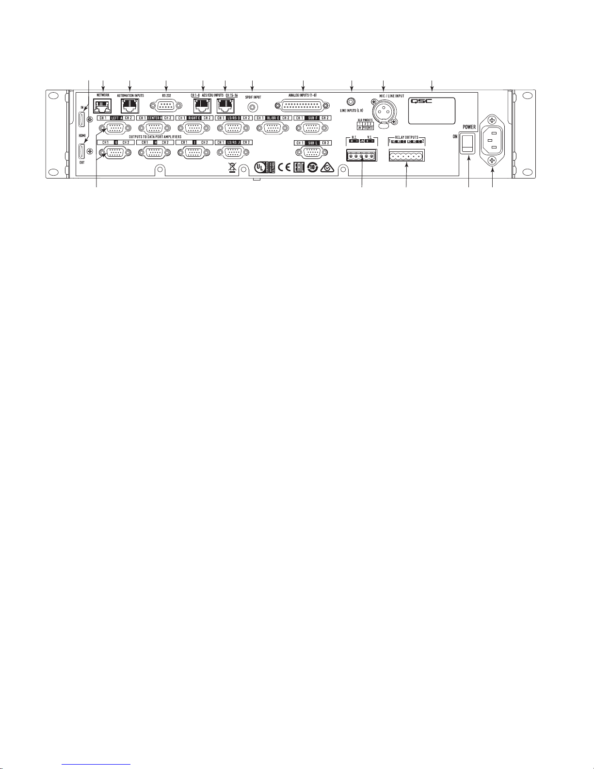
12 13 14 15 16
1 2 3 4 5 6 7 8 9 10 11
MODEL: DPM 300 / 300H
SERIAL: 123456789
123456789
— Figure 2 —
1. HDMI IN / OUT (DPM 100H and DPM 300H only) – Extracts audio
from incoming HDMI stream and passes stream directly to output
HDMI port. Includes Dolby Digital Plus™, and DTS-HD® decoder.
2. NETWORK (RJ45) – 10/100 Mbps Ethernet port for DPM Manager,
3rd party control, or SNMP management and remote access.
3. AUTOMATION INPUTS (RJ45) – contact closures (control presets,
mute etc.)
4. RS 232 – Serial communications port for 3rd party control/automation
5. CH 1-8 AES/EBU INPUTS (RJ45) – AES3 pairs 1 through 4 (digital
audio channels 1 through 8)
6. CH 15-16 AES/EBU INPUTS (RJ45) – AES3 pair 8 (digital audio
channels 15 and 16, normally HI and VI)
7. SPDIF INPUT – SPDIF multi-channel digital input for non-sync/
alternative content. Includes Dolby Digital Plus™ (DPM 100H and
DPM 300H only) or Surround LtRt Matrix decoding.
DPM Manager Software
8. ANALOG INPUTS (DB-25) – connect to D-Cinema server or film
processor with analog outputs
9. LINE INPUTS (L R) (3.5 mm TRS) – Stereo analog line-level inputs
10. MIC / LINE INPUT (XLR) – Mono analog input accepts microphone
or line-level signals (with phantom power)
11. Serial Number and Model
12. OUTPUTS TO DataPort™ AMPLIFIERS (HD-15) connectors – For
QSC DataPort amplifiers. There are 9 DataPorts on DPM 100/100H; 11
DataPorts on DPM 300/300H.) Use only QSC-supplied DataPort cables.
13. H.I. / V.I. – Hearing impaired and visually impaired special mix
outputs
14. RELAY OUTPUTS – mechanically de-coupled control outputs (curtain,
lighting control, and so on.)
15. POWER ON / OFF switch
16. IEC connector – AC mains power connector
DPM Manager is used to configure and manage your DPM and to configure the network settings if required.
Your computer must meet the following minimum requirements:
1. Computer with Windows® 7, 8, or 10 OS (32 or 64 bit) or MAC OS 10.9.5 or higher
2. 4 GB of RAM or greater
3. Display resolution of at least 1024 x 768
Setup Overview
Initial configuration of the DPM is performed through QSC’s DPM Manager software, which must be installed on a Windows® or MAC PC or laptop
computer. Once the software is installed on the computer, the computer can then be connected to the DPM using a USB or Ethernet connection.
A system designer would typically begin high-level configuration by defining the basic system topology and distribution of audio within the
DPM Manager application. This involves selecting the audio sources for the DPM program inputs, auditorium sound format, amplification, and speaker
design. Presets can be created to accommodate multiple audio sources or distribution topologies (i.e.., to support different configurations for the main
theatre presentation and for alternative content/non-sync audio) and/or to support multiple auditorium mixes or multi-use applications.
Once the high-level configuration is complete, the rest of system can be connected to the DPM and/or powered up and completion of the DSP
configuration, assignment of levels, and other system tuning can commence.
TD-000515-01-D
4
Page 5

NOTE: Recalling system presets and adjusting system parameters such as output and monitor levels, monitor tap points, and so on,
can be made through the front panel user interface.
The Setup Overview on the following pages is a general application guide showing the installation steps required for a basic system. Refer to the Help
Files in DPM Manager for detailed setup and configuration instructions and for system examples. The QSC Cinema Products web pages are also a
good source of information for application notes and system design assistance.
The following assumes that the DPM has been unpacked and mounted.
1. Install Software
Download the DPM Manager installation file from QSC.com. Follow the instructions to install.
2. Configure DPM
After DPM Manager is installed, connect a USB cable between the DPM and the computer. Turn the DPM on, launch DPM Manager and follow the
prompts on screen. Refer to the Help Files for instructions on how to configure the basic operating parameters of the DPM (source inputs, format,
presets, etc).
3. Attach Amplifiers
Connect DataPort outputs on the DPM rear panel to DataPort inputs on QSC’s DCA or PL3 Series amplifiers using QSC approved DataPort cables.
4. Connect Audio
Connect cinema audio sources to the appropriate DPM rear panel input connectors. Main sources can come from digital content servers or analog film
processors. Additional analog and digital inputs are provided for alternative content sources, live feeds, DVD players, mic/paging sources etc. Connect
the Hearing Impaired and Visually Impaired special mix outputs to appropriate external devices as needed.
5. Connect Automation
Connect appropriate external control devices to the DPM’s automation Inputs. Connect the Relay Outputs to any external devices to be controlled.
6. Tune System
Once the basic DPM operating configuration is defined and all of the connections are in place, it’s time to power up the rest of the rack, complete the
DSP setup, tune the system and run through final check.
Refer to additional information in this Hardware User Manual and in the software Help Files for further setup and configuration details to complete this step.
Configuration and Networking
The DPM offers a variety of options for configuring and managing the product and an entire cinema sound system locally or remotely. Local DPM
configuration and system management are provided through directly applied connections to the DPM via universal serial bus (USB), the DPM front
panel LCD and buttons or through a local Ethernet link. Remote and system-wide management are possible through more sophisticated network
implementations and/or via wide area network (WAN) topologies, Internet access or 3rd party subscription services that make use of the DPM thirdparty API or SNMP.
Basic configuration of the DPM product is performed through the USB interface on the product front panel or via the Ethernet connection on the rear
panel. The system designer connects to the DPM’s USB port with a Windows or MAC laptop or PC running the DPM Manager software application.
DPM Manager offers all the setup tools and system management objects to configure the auditorium audio format, selection of audio source material,
configure the DSP signal path, apply crossovers, EQ etc., define the routing of audio to the amplifiers, define the system speakers and speaker
processing etc. Once the basic configuration is complete, the system designer can define custom up to 16 custom Presets that can be recalled for
different auditorium setups. For example, a Preset can be created for the primary presentation content. Another Preset can be created for non-sync
or alternative content. And yet another Preset can be created for live application use such as seminars or corporate events. Once these Presets are
created they become accessible via the DPM front panel user interface.
In addition to basic configuration, DPM Manager can be used to monitor health, status, and performance of the system via the product’s USB or
Ethernet interface.
TD-000515-01-D
5
Page 6

USB Connection to DPM
Figure 1 item 12 illustrates the product’s front-panel USB Type B port. Connect the USB cable to a laptop running QSC’s DPM Manager to configure
the DPM.
Local Ethernet connection to DPM
Figure 2 item 2 is used to connect the DPM to a network switch to allow setup, control and monitoring over Ethernet.
Configuring the DPM
DPM Manager is used to configure the DPM product. This includes configuring the device properties, the DSP objects, audio and control I/O and
Presets. The network communications properties must be configured using DPM Manager over USB so that all networking properties are in place
before the DPM is added to a local area network (if your deployment requires networking).
Once the DPM product is configured, DPM Manager can then be used to manage one or more DPM products over a local area network. Alternately,
an SNMP-based management system may be used to monitor and control the DPM.
Refer to the information in the DPM Manager Help for additional information on product configuration, management and network connectivity.
Connections
AC Power Cord
Insert the molded receptacle of the AC power cord into the AC power inlet on the back of the DPM product. Plug the AC line connector into an AC
outlet. The power supply on the DPM product will accept from 100 to 240V, 50 to 60 Hz.
Network
Connect one end of a data communications cable terminated with an RJ45 plug into the Ethernet receptacle on the rear panel of the DPM product.
Ensure that the lock tab on the cable engages with the RJ45 receptacle on the DPM rear panel connector. Note: data communications cabling must be
rated CAT-3 or better for 10 Mbps network connections or rated CAT-5 or better for 100 Mbps network connections.
Hearing and Visually Impaired Outputs (H.I./V.I.)
The Hearing Impaired and Visually Impaired special mix outputs are balanced outputs that are combined into a single 5-terminal
Euro style (a.k.a. Phoenix) receptacle. This combo receptacle includes a common ground for both the H.I. and V.I. outputs.
Terminate the mating 5-terminal Euro plug and insert it into the DPM rear panel receptacle as shown in Figure 3. The DPM
rear panel label provides a pin-out of the receptacle signals. Note: a standard 3-terminal plug may be used if only one output is
required.
Automation Inputs
The automation inputs use an RJ45 connector. The Automation Inputs can be connected to relay contacts or a switch.
Relay Outputs
Two relay outputs are provided via two 3-terminal Euro style (a.k.a. Phoenix) receptacles. Relay contacts are floating
and rated for 30 VDC at 1A. Each output includes one common terminal, one normally open contact (N.O.) and one
normally closed (N.C.) contact. These terminals are labeled C, NO and NC, respectively on the DPM rear panel. When
the relay is not energized, the C terminal is connected to the NC contact and the NO contact is not connected. When
the relay is energized, the C terminal is connected to the NO contact and the NC contact is not connected.
Pin # Description
— Figure 3 —
Automation In (RJ45)
1 GPI 1
2 GPI 2
3 GPI 3
4 GPI 5
5 GPI 6
6 GPI 4
7 UNUSED
8 GND
TD-000515-01-D
6
Page 7
DataPorts
QSC DataPorts on the DPM rear panel are intended to interface to QSC amplifiers with v1 DataPorts. These are the all-capable DataPorts, which are
included on DCA and PL3 series amplifiers. All DataPorts use the HD15 connector format and connect to QSC amplifiers via data communications
cables having male HD15 connectors on both ends. These are commonly referred to as VGA cables. Note: though many off-the-shelf VGA cables may
work with satisfactory results, the QSC DataPort specification requires that all conductors be present and that all audio I/O conductors be shielded.
Therefore, only QSC supplied DataPort cables should be used. A variety of lengths are available through QSC’s Technical Services Group. To connect
a DataPort cable between a DPM DataPort and an amplifier DataPort, attach the cable’s male connectors to the HD15 ports and finger tighten the
thumb screws on the connectors.
Ancillary Interfaces
A single Mic/Line Input is accessible on the DPM rear panel. This input can be used for mono non-sync sources or for connecting a microphone for
local paging or announcements into the auditorium or to support various corporate or live events requiring a microphone. Alternately a microphone
can be permanently connected to provide SPL metering of the theater. Phantom power may be enabled via DPM Manager configuration or via the
DPM front panel interface. The Mic/Line Input uses a standard 3-conductor XLR receptacle.
L/R analog line input connectors and a multi-channel digital SPDIF input are accessible on the DPM rear panel. These connectors accommodate nonsync sources appropriate for alternative content, advertising, corporate or live event feeds.
HDMI In/Out connectors are provided to allow audio inputs from alternate content sources with HDMI outputs such as laptops or satellite receivers.
The HDMI input signal is passed through to HDMI output for connection to downstream video devices.
NOTE: All ancillary interfaces use standard cables that are readily available through retailers specializing in computer equipment,
musical equipment, pro audio or home electronics.
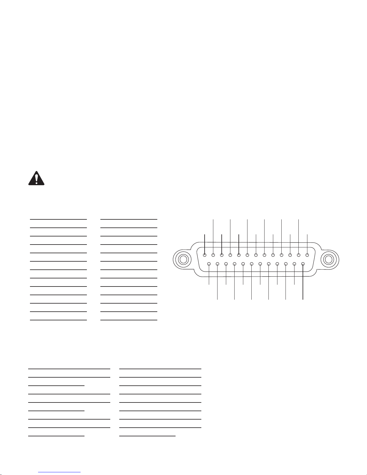
Main Analog Input Connector Pinout (DB25 Female)
Pin # Description
1 Chassis ground
2 Left +
3 Left extra -
4 Chassis ground
5 Center +
6 Right extra -
7 Chassis ground
8 Right +
9 Chassis ground
10 Surround left -
11 Surround right -
12 Subwoofer -
13 Chassis ground
Digital (AES3) Input Connector Pinout (RJ45)
AES/EBU INPUTS 1-8
Pin # Description Channel
1 AES Pair 1: +
2 AES Pair 1: -
3 AES Pair 2: + C, Sub
4 AES Pair 3: -
5 AES Pair 3: +
6 AES Pair 2: - C, Sub
7 AES Pair 4: +
8 AES Pair 4: -
Pin # Description
14 Left -
15 Chassis ground
16 Left extra +
17 Center -
18 Chassis ground
19 Right extra +
20 Right -
21 Chassis ground
22 Chassis ground
23 Surround left +
24 Surround right +
25 Subwoofer +
Shell Chassis ground
L, R
LS, RS
BL, BR
AES/EBU INPUTS 15-16
Pin # Description Channel
1 AES Pair 1: + Unused
2 AES Pair 1: - Unused
3 AES Pair 2: + Unused
4 AES Pair 3: - Unused
5 AES Pair 3: + Unused
6 AES Pair 2: - Unused
7 AES Pair 4: +
8 AES Pair 4: -
HI, VI
13
25
12
10
11
23
24
8
9
21
22
— Figure 4 —
20
2
4
6
5
7
17
19
16
18
13
15
14
TD-000515-01-D
7
Page 8

Specifications
Parameter Specification
Front Panel Controls and Indicators
Monitor Volume/parameter
adjust
Setup mode indicator Yellow LED
LCD 128 x 64 bit Monochrome LCD
Master Mute indicator Red LED
Master Mute Push button
Master Volume Rotary encoder
Power on indicator Green LED
Fault detect indicator Yellow LED
USB Type B port Config and management interface
Monitor output 3.5 mm TRS
Rear Panel Connectors
Network RJ45 10/100 Mbps network management
Automation Inputs RJ45 – 6 contact closure inputs
RS232 DB-9 Serial Interface
Channels 1-8 AES3/EBU
Inputs
Channels 15-16 AES3/EBU
Inputs
S/PDIF Input RCA — Stereo digital audio interface and Lt/
Analog Inputs (1-8) DB-25
Line Inputs 3.5 mm TRS — Stereo Left and Right and Lt/
Mic/Line input XLR — Mic +15V phantom power or line level
HDMI input/output Type A female connectors
DataPort connectors HD-15 (9 or 11) — QSC amplifier interface
H.I./V.I. output 5-pin Euro-style (x1) – common GND
Relay outputs 3-pin Euro-style (x2) – max 30 VDC
Power switch Rocker switch
Monitor Speaker
Speaker 2”x 3.5" full-range
Impedance 4 Ω
Amplifier output power 10 watts Class D
Frequency response 20 Hz – 20 kHz (± 2 dB)
General Audio Performance Requirements
A/D conversion 24-bit delta-sigma, 48 kHz
Frequency response: 20 Hz to 20 kHz (+- .5dB)
Main Analog Input (DB25F - 8 channel)
Active balanced input
Input impedance: 20k Ohm
Max analog input level: +14.2 dBu (4.0 Vrms)
Dynamic range
(unweighted):
Dynamic range
(A-weighted):
THD+N at 2 dB below clip: < 0.003%
Rotary encoder
RJ45
RJ45
Rt Matrix
Rt Matrix
Analog Inputs/Outputs
> 106 dB
> 108 dB
Parameter Specification
Mic/Line Input (XLR)
Active balanced input
Input impedance: 2.2k Ohms
Max analog input level: 26 dBu
Dynamic range
(unweighted):
Dynamic range
(A-weighted):
THD+N at 10 dB below clip
(26dBu sens):
THD+N at 10 dB below clip
(21dBu sens):
Input gain 0 to 60dB in 1 dB steps
CMRR typical 20 Hz – 20
kHz:
EIN: < -122 dB
Phantom power voltage: 15V
Stereo Line Inputs (3.5mm minijack)
Unbalanced input
Input impedance (4dBu
sens):
Max analog input level
(4dBu sens):
Input impedance (-10dBV
sens):
Max analog input level
(-10dBV sens):
Headroom (all sens): > 10dB
Dynamic range
(unweighted):
Dynamic range
(A-weighted):
THD+N at 2 dB below clip: < 0.003%
DataPort Outputs (HD15)
Max output level: 14 dBu
Dynamic range
(unweighted):
THD+N at 2dB below clip: <.002 %
HI/VI Outputs (5-pin Euro-style with common GND)
Balanced output
Max output level: 18 dBu (adjustable)
Dynamic range
(unweighted):
THD+N at 2dB below clip: <.002 %
Monitor Headphone Output (Front Panel 3.5mm minijack)
Unbalanced output
Max output level: 21 dBu
Dynamic range
(unweighted):
THD+N at 2dB below clip: <.025 %
> 106 dB
> 108 dB
< 0.02%
< 0.003%
> 50dB
> 10k Ohms
14 dBu (4.2 Vrms)
2.7k Ohms
0 dBV (1 Vrms)
> 106 dB
> 108 dB
> 109 dB
> 109 dB
> 109 dB
TD-000515-01-D
8
Page 9

Parameter Specification
®
Digital Inputs/Outputs
AES/EBU Digital Inputs (RJ45)
Balanced input
Input sample rate 48 kHz or 96 kHz
S/PDIF Digital Inputs (Mono RCA)
Unbalanced input
Stereo PCM or Dolby Digital
Plus™ (DPM100H only)
HDMI Input/Output (DPM 100H and DPM 300H only)
HDMI Type A Connector
PCM, DTS-HD®, or
Dolby Digital Plus™
Other
Line voltage requirements 100 VAC – 240 VAC, 50/60 Hz
Dimensions (H/W/D): 3.5"(2 RU) x 19" x 15"
Accessories included 6 ft UL/CSA line cord, Connector Kit
Parameter Specification
Relay outputs (2)
3-pin Euro-style
Normally open, normally
closed and common
Max 30 VDC @ 1A
Automation inputs (RJ45 - 6 GPI)
Max input voltage 5V (3.3V typical)
TTL compatible dry contact
closure
Network / SNMP
Protocol Standard TCP/IP implementation over Ethernet
or Fast Ethernet. 3rd party interface may use
UDP/ IP or TCP/IP.
Data rate 10/100 Mbps
Connection requirements Cat-5 UTP cable or better (100m maximum
length), direct connection to wired network
switch ports only, dedicated LAN or VLAN
Mailing Address:
QSC, LLC
1675 MacArthur Boulevard
Facsimile Numbers:
Sales & Marketing FAX: (714) 754-6174
Customer Service FAX: (714) 754-6173
Costa Mesa, CA 92626-1468 USA
World Wide Web:
Telephone Numbers:
Main Number: (714) 754-6175
Sales & Marketing: (714) 957-7100 or toll free (USA only) (800) 854-4079
Customer Service: (714) 957-7150 or toll free (USA only) (800) 772-2834
©2018 QSC, LLC. All rights reserved. QSC, the QSC logo are registered trademarks of QSC, LLC in the U.S. Patent and Trademark office and other countries. Intrinsic Correction is
a trademark of QSC, LLC. Windows is a trademark of Microsoft Corp.
For DTS patents, see http://patents.dts.com. Manufactured under license from DTS, Inc. DTS, the Symbol, DTS in combination with the Symbol, the DTS-HD logo, and DTS-HD
Master Audio are registered trademarks or trademarks of DTS, Inc. in the United States and/or other countries. © DTS, Inc. All Rights Reserved.
Manufactured under license from Dolby Laboratories. Dolby, Dolby Audio, Dolby Digital Plus, and the double-D symbol are trademarks of Dolby Laboratories. Confidential
unpublished works. Copyright 1992-2015 Dolby Laboratories. All rights reserved.
All other trademarks are the property of their respective owners. Patents may apply or be pending.
http://patents.qsc.com.
www.qsc.com
E-mail:
 Loading...