

Page 1
CMX Series
User Manual
CMX 2000V Amplifier
TD‑000323‑00
*TD‑000323‑00*
Page 2
2
IMPORTANT SAFETY PRECAUTIONS AND EXPLANATION OF SYMBOLS
WARNING!
The lightning flash with the arrowhead symbol within an equilateral triangle is intended to alert the user to the presence of
uninsulated “dangerous” voltage within the product’s enclosure that may be of sufficient magnitude to constitute a risk of
shock to humans.
The exclamation point within an equilateral triangle is intended to alert the user to the presence of important operation and
maintenance (servicing) instructions in this manual.
1. Read these instructions.
2. Keep these instructions.
3. Heed all warnings.
4. Follow all instructions.
WARNING: To prevent fire or electric shock, do not expose this equipment to rain or moisture. Do not use this apparatus
near water.
5. Clean only with a dry cloth.
6. Allow a minimum of 6" (152 mm) clearance behind cabinet for convection cooling. Keep anything that might restrict airflow from the rear
of the enclosure (i.e. draperies, fabric, etc.). Do not block any ventilation opening. This product is a power amplifier that produces heat.
7. Do not install near any heat sources such as radiators, heat registers, stoves, or other apparatus (including amplifiers) that produce heat.
8. Do not defeat the safety purpose of the grounding-type plug on the three-pronged “Edison” style power cable. The grounding plug has two
blades and a grounding prong. The third prong is provided for your safety. If the provided plug does not fit your outlet, consult an electrician for the replacement of the obsolete outlet. Do not cut off the grounding plug or use an adapter that breaks the grounding circuit. This
apparatus must be properly grounded for your safety.
9. Protect the power cord from being walked on or pinched, particularly plugs, convenience receptacles, and the point where they exit from
the apparatus.
10. The appliance coupler is the AC mains disconnect and should remain readily operable after installation.
11. Use only attachments/accessories specified by QSC Audio Products, LLC.
12. Use only with hardware, brackets, and components sold with the apparatus or by QSC Audio Products, LLC.
13. Unplug the apparatus during lightning storms or when unused for long periods of time.
14. Refer all servicing to qualified service personnel. Servicing is required when the apparatus has been damaged in any way, such as power
supply cord or plug is damaged, liquid has been spilled or objects have fallen into the apparatus, the apparatus has been exposed to rain
or moisture, does not operate normally or has been dropped.
15. The appliance shall not be exposed to dripping or splashing and no objects filled with liquids, such as vases, shall be placed on
the apparatus.
1
Page 3

Warranty (USA only; other countries, see your dealer or distributor)
Disclaimer
QSC Audio Products, LLC is not liable for any damage to amplifiers, or any other equipment that is caused by negligence or improper installation and/
or use of this loudspeaker product.
QSC Audio Products 3-Year Limited Warranty
QSC Audio Products, LLC (“QSC”) guarantees its products to be free from defective material and / or workmanship for a period of three (3) years from
date of sale, and will replace defective parts and repair malfunctioning products under this warranty when the defect occurs under normal installation and
use - provided the unit is returned to our factory or one of our authorized service stations via prepaid transportation with a copy of proof of purchase (i.e.,
sales receipt). This warranty provides that the examination of the return product must indicate, in our judgment, a manufacturing defect. This warranty
does not extend to any product which has been subjected to misuse, neglect, accident, improper installation, or where the date code has been removed
or defaced. QSC shall not be liable for incidental and/or consequential damages. This warranty gives you specific legal rights. This limited warranty is
freely transferable during the term of the warranty period. Customer may have additional rights, which vary from state to state.
In the event that this product was manufactured for export and sale outside of the United States or its territories, then this limited warranty shall not apply.
Removal of the serial number on this product, or purchase of this product from an unauthorized dealer, will void this limited warranty.
Periodically, this warranty is updated. To obtain the most recent version of QSC’s warranty statement, please visit www.qscaudio.com.
Contact us at 800-854-4079 or visit our web site at www.qscaudio.com.
© Copyright 2010, QSC Audio Products, LLC
QSC is a registered trademark of QSC Audio Products, LLC
“QSC” and the QSC logo are registered with the U.S. Patent and Trademark Office
All trademarks are the property of their respective owners.
2
Page 4
4
Introduction
Thank you for purchasing this QSC power amplifier. Please read the following directions to obtain the best results. The rugged fan-cooled, 2-channel,
3RU amplifier provides high-value performance and power in a strong, compact chassis.
Features
• Independent, user-defeatable clip limiters
• Fully selectable low-frequency filtering; choice of 30 or 50 Hz roll-off
• STEREO (dual channel), PARALLEL INPUT, or BRIDGE MONO operating modes
• Balanced inputs — XLR, ¼" (6.3 mm) TRS, and barrier strip
• Pluggable terminal block and Speakon™ outputs
• 21 detent attenuation knobs
• Front panel LED indicators for power, signal, and clip
• Attenuation control security plate
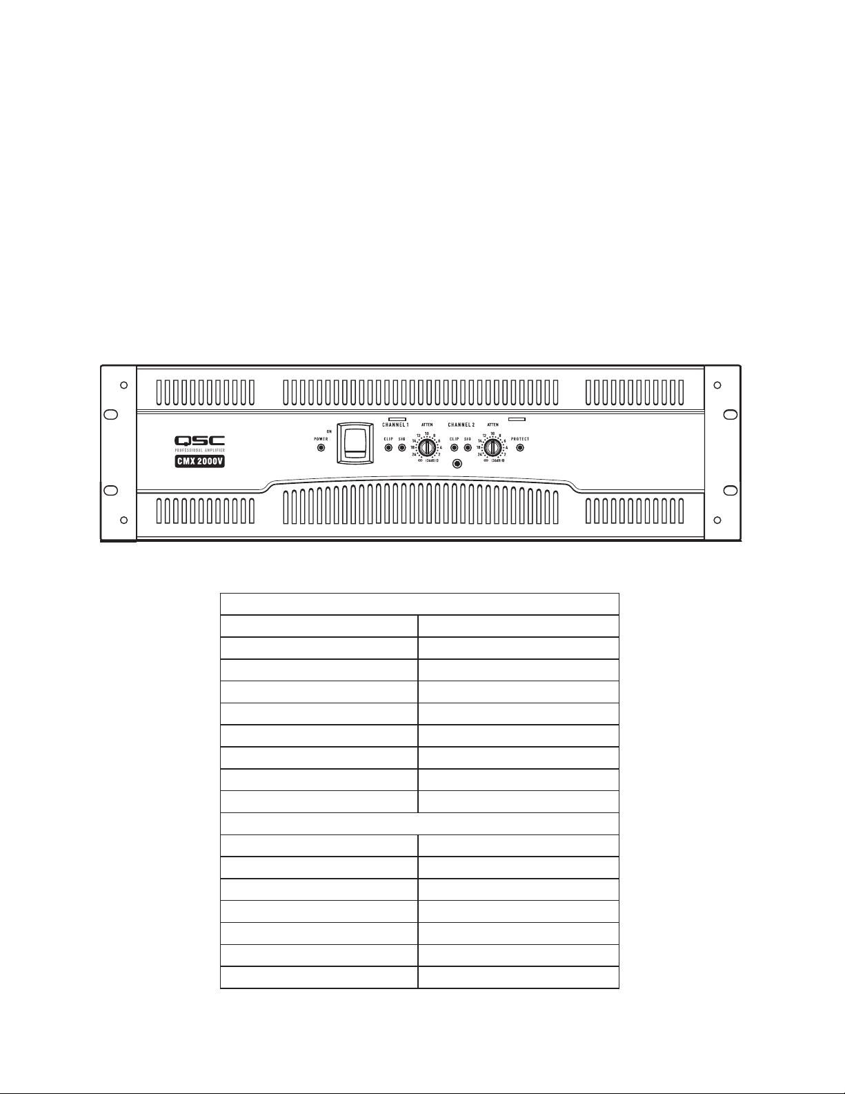
— Figure 1 —
STEREO Mode (Both channels driven)
FTC: 20 Hz – 20 kHz @ 0.1% THD
8 ohms per channel 1050 W
4 ohms per channel 1600 W
EIA: 1 kHz @ 1% THD
8 ohms per channel 1100 W (0.1% THD)
4 ohms per channel 2000 W
2 ohms per channel 2500 W
70V - Direct Drive 2500 W
100V - Direct Drive 1000 W
BRIDGE MONO mode
FTC: 20 Hz – 20 kHz @ 0.1% THD
8 ohms 3200 W
EIA: 1 kHz @ 1% THD
8 ohm 3600 W
4 ohms 5000 W (0.1% THD)
140V - Direct Drive 5000 W
100V - Direct Drive 3600 W
— Table 1 —
3
Page 5

Unpacking
Factory packed carton contains:
• CMX amplifier
• User's manual
• Adhesive rubber feet (for non-rack mount applications)
• Attenuation security plate
• Rear rack ear mounting kit
• IEC-type detachable power cord
Use the same type carton when shipping the amplifier.
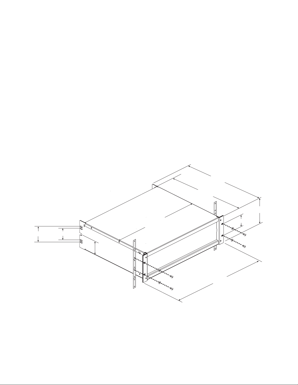
Rack Mounting
Use four screws and washers to mount the amplifier to the equipment rack rails. To use the amplifier outside a rack, attach the self-adhesive rubber
feet to the bottom. Use the rear rack ear support kit to support the rear of the amplifier for portable use. Refer to (Figure 2) for planning.
vertical centerline of holes is 0.40" (10.2 cm)
from back edge
hole size = 0.25" x 0.47" (06.4 x 11.9 mm)
3.00" (7.6 cm)
notch is 0.40" high x 0.50"
deep (1.0 x 1.2 cm)
2.25" (5.7 cm)
2.60" (66 mm)
17.40" (442 mm)
— Figure 2 —
15.8" (402 mm)
14.8" (375 mm)
5.2" (132 mm)
2.25" (57 mm)
18.90" (482 mm)
4
Page 6

6
1 1
2
3
44
5
6
5
7
7
8
9
10 11
1
2
3
4
5 6
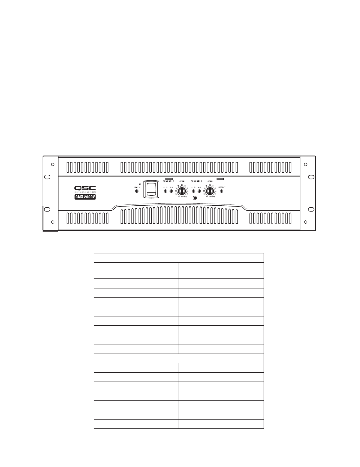
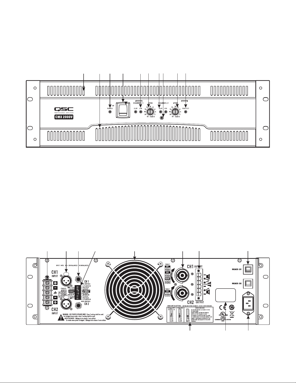
Front Panel (Figure 3)
1. Cooling air exhaust vents
2. Power On LED
3. Power switch
4. Attenuation controls
5. Clip and Signal LEDs
6. Protect mode LED
7. Security plate screw
— Figure 3 —
Back Panel
1. Barrier strip input connectors
2. XLR input connectors
3. TRS (1/4") input connectors
4. Mode switches and settings
5. Cooling air inlet vents
6. Speakon™ output connectors
7. Terminal block connector
8. AC circuit breakers
9. Switch settings for PARALLEL INPUTS, STEREO, BRIDGE MONO
10. Serial number label
11. IEC power inlet (power cord connector)
— Figure 4 —
5
Page 7
Features and Setup
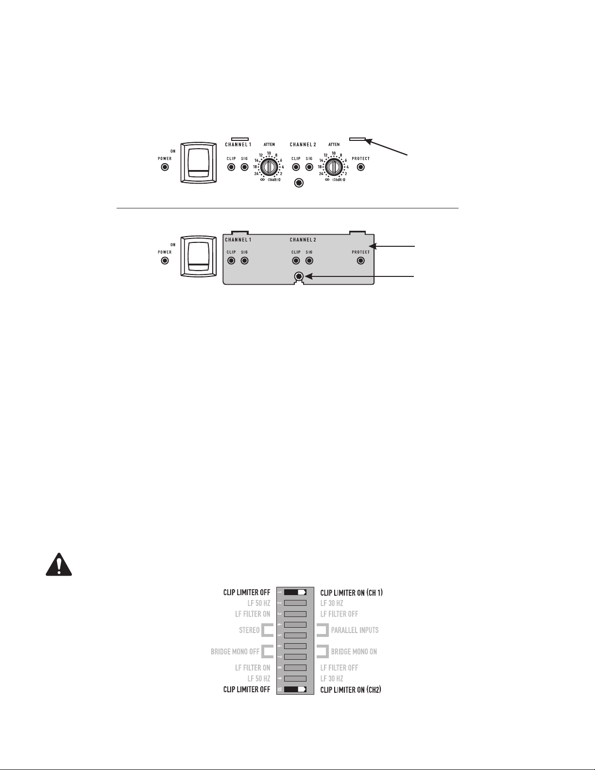
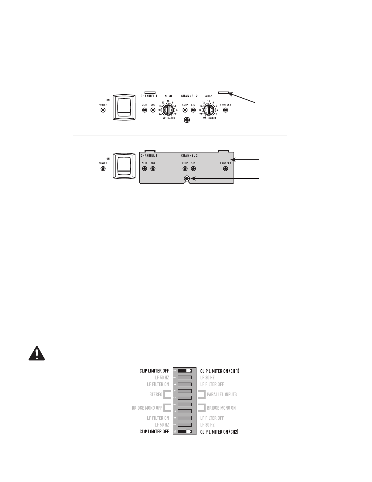
Attenuation Control Security Plate
The Attenuation control security plate (Figure 5) provides protection against accidently adjusting the Attenuation controls on the amplifier face.
Attach the plate, after making final adjustments to the Attenuation controls, by sliding the tabs into the two installation slots. Secure in place with the
attachment screw.
Attenuation plate
installation slots (2)
Attenuation plate not installed
Attenuation plate
Attenuation plate
attachment screw
Attenuation plate installed
— Figure 5 —
Setting the Mode Switches
The CMX 2000V has mode switches for STEREO, PARALLEL INPUTS, or BRIDGE MONO modes. Each channel has independent clip limiting and low
frequency filtering.
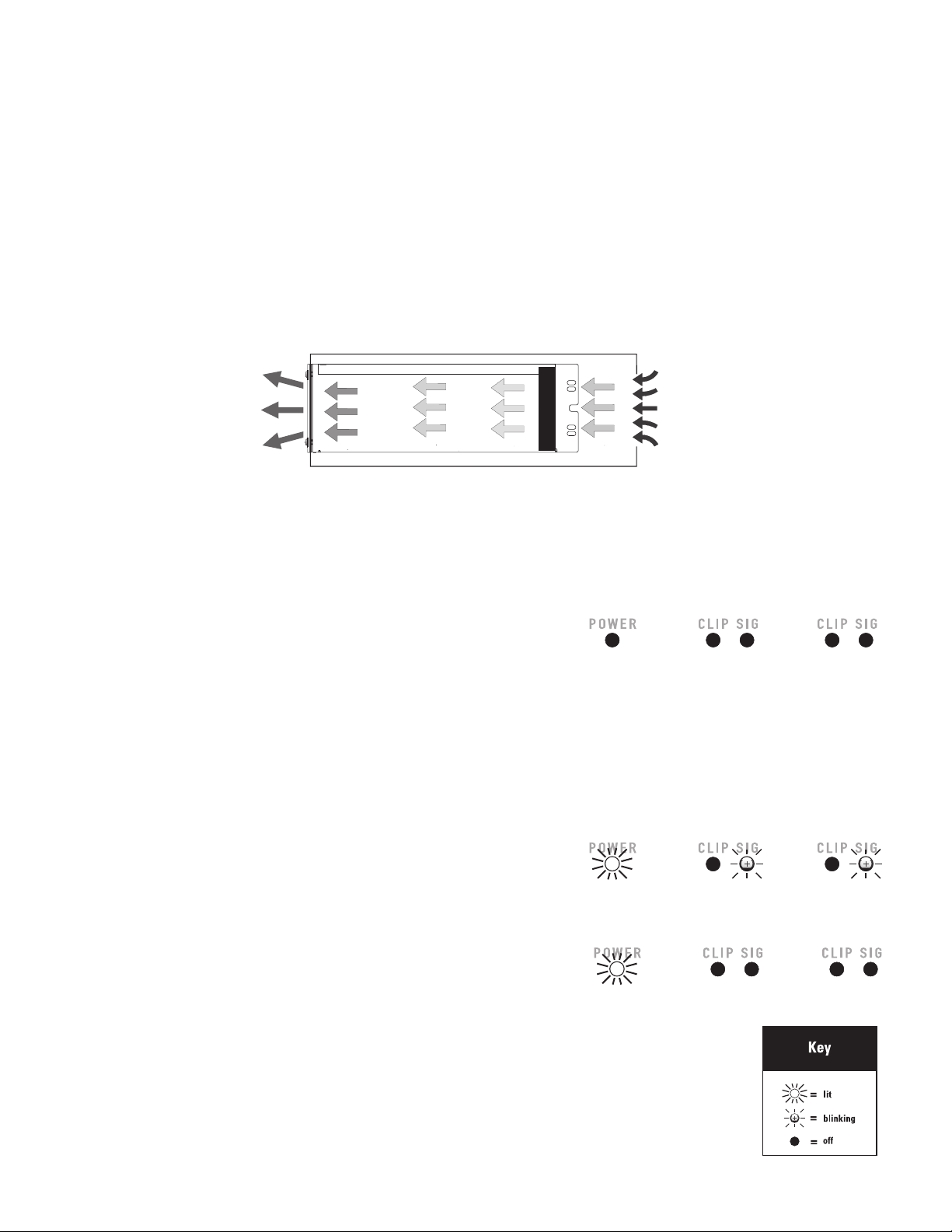
Clip Limiter
What it is
When the audio signal drives the amp's output circuit beyond its power capability, it clips, flattening the peaks of the waveform. The clip limiter detects this and reduces the gain to minimize the amount of overdrive. To preserve as much of the program dynamics as possible, limiting reduces the
average program level until peaks barely clip.
The limiter only responds to actual clipping, and automatically compensates for load and voltage variations. Each channel has its own clip limiter, and
you can switch it on or off independently, as shown in (Figure 6).
When to use it (or not)
When driving full-range speakers, clip limiting reduces high-frequency distortion caused by bass overloads. It also protects higher frequency drivers
from excess overdrive and harsh clipping harmonics.
When driving subwoofers, some users let the amplifier clip without limiting because it gives extra “punch” to kick drums and similar sounds.
CAUSION: In bi-amplifier systems, excessive limiting will affect the frequency balance.
— Figure 6 —
6
Page 8
8
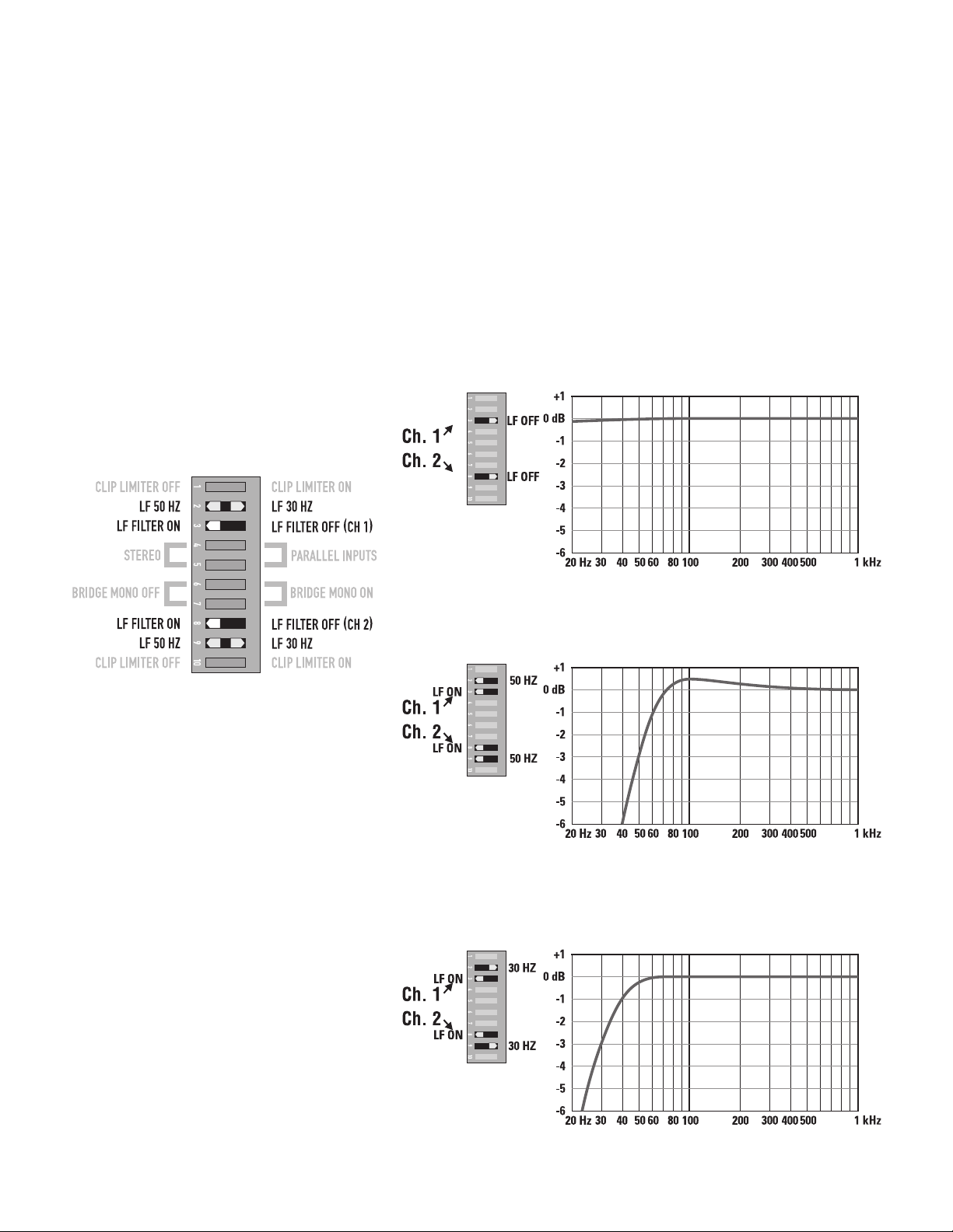
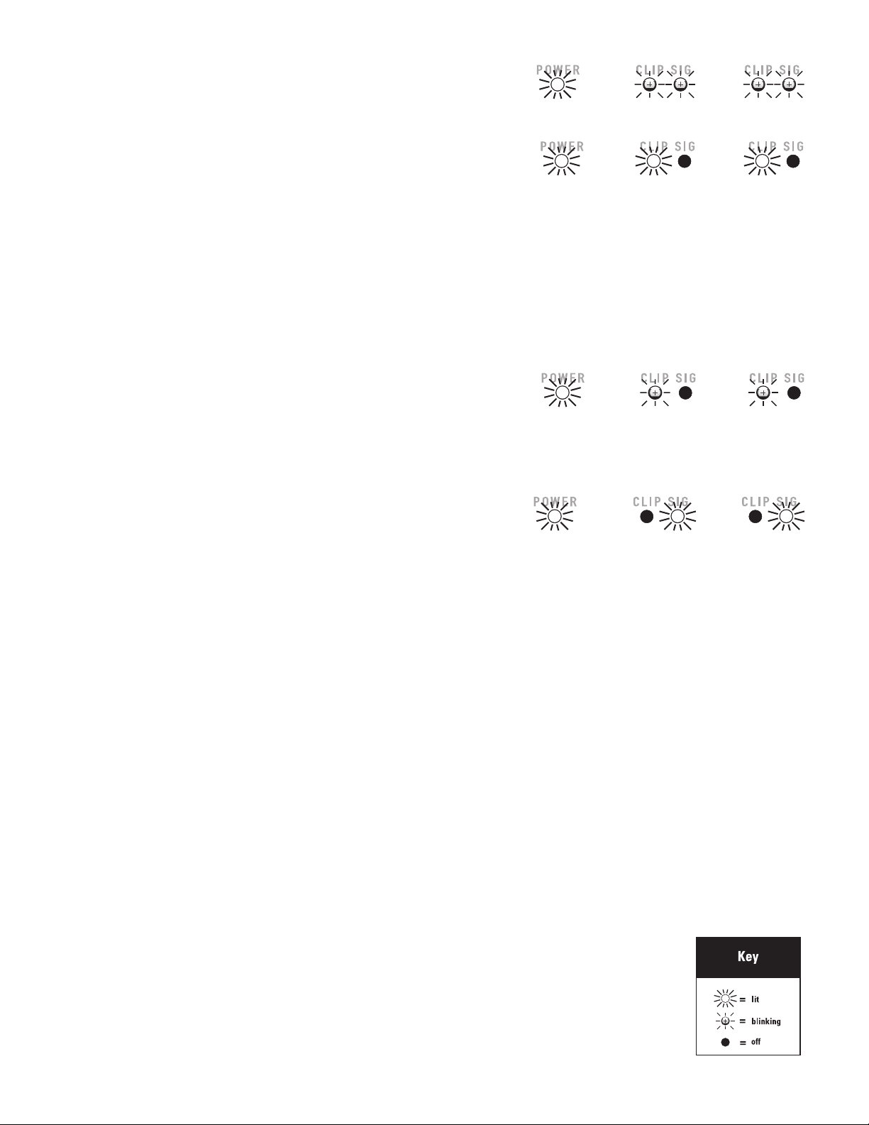
Input Low-Frequency Filter
What it is
The low-frequency (LF) filter rolls off signals below either 30 Hz or 50 Hz (Figure 9 and Figure 10). Each channel has a 12 dB per octave Low
Frequency Filter to prevent cone over-excursion, making more power available for the loudspeaker’s rated frequency range. This reduces distortion
and prevents amplifier overload.
The filter settings for each channel are controlled individually through the DIP switch settings shown in (Figure 7). When the filter is turned off
(Figure 8), a 5 Hz roll off protects against DC or deep sub-audio inputs.
When to use it (or not)
As a rule, your speakers will sound better with proper filtering. Unless you already have filtering in a preceding device, match the setting to the low
frequency rating of your speakers. Vented (bass reflex, ported, etc.) speakers are especially sensitive to cone over-excursion at frequencies below their
rated limit.
The 50 Hz filter works well with most compact full-range speakers, and has a slight boost at 100 Hz for greater fullness. The 30 Hz filter is intended
for subwoofers and large full-range cabinets. The LF FILTER OFF position should be used only for applications such as studio playback monitoring,
where you need to know if there are unwanted sub-audio signals present in your mix.
— Figure 7 —
— Figure 8 —
— Figure 9 —
— Figure 10 —
7
Page 9

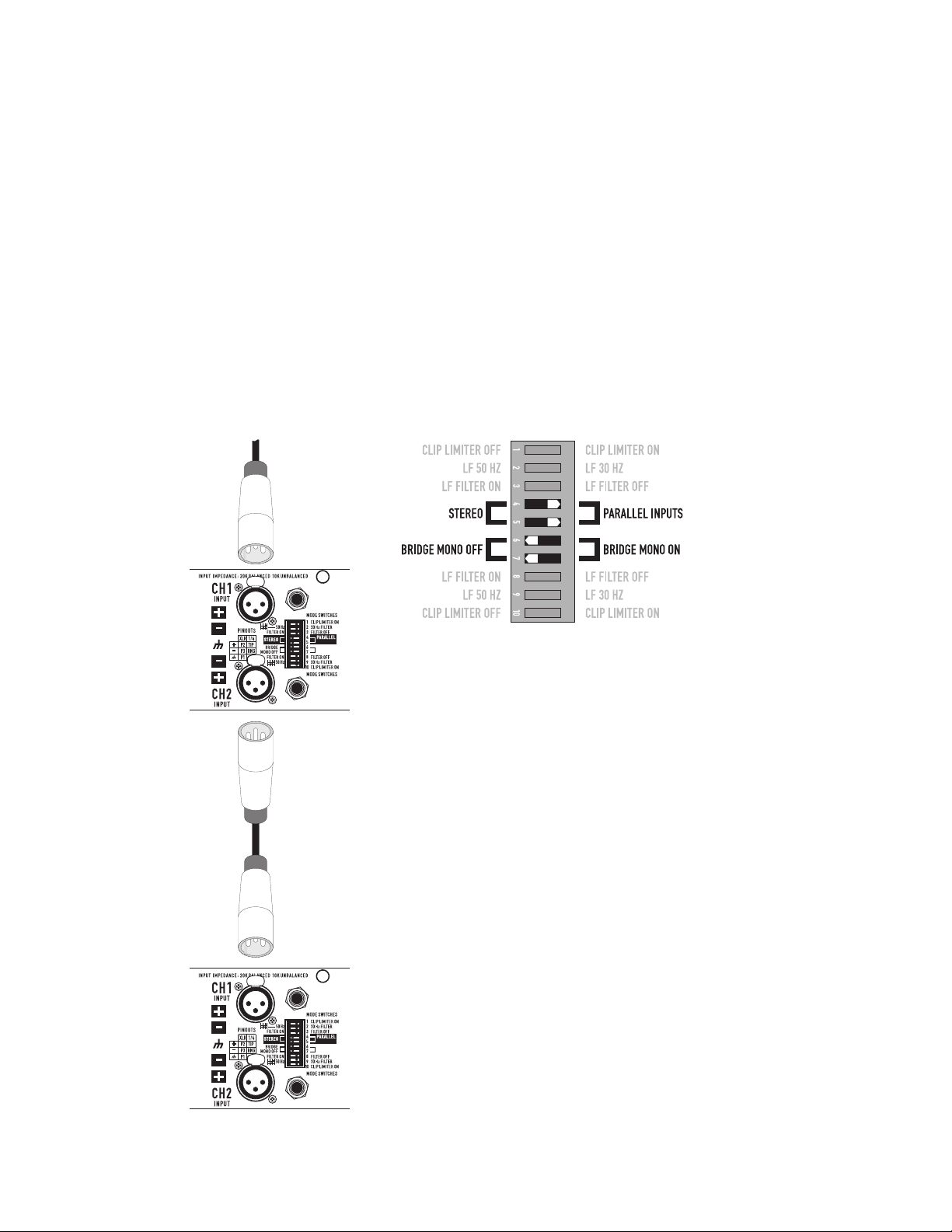
PARALLEL INPUTS Mode
What it is
The PARALLEL INPUTS switches let you operate the amplifier in a parallel mode, delivering the same signal to both channels without using a Y cable.
Each channel drives its own speaker load, with independent gain, filtering, and clip limiting.
Set switch positions 4 and 5 to PARALLEL INPUTS to couple the inputs together (Figure 11). Turn the switches to STEREO for stereo, bi-amping, or
other 2-channel modes.
In PARALLEL INPUTS mode, you can use the other set of input connectors to carry the signal to other amplifiers (Figure 12). This is often
called a daisy-chain.
When to use it
Use the PARALLEL INPUTS mode when driving two speakers with one input signal. This maintains separate control of gain, filtering, and limiting.
Note: If you’re using a balanced signal, use only balanced patch cables; even one unbalanced cable will unbalance the entire signal chain, possibly
causing hum.
Note: Turn off the “Parallel Inputs” switches when feeding the amp two separate signals.
— Figure 11 —
— Figure 12 —
8
Page 10
10
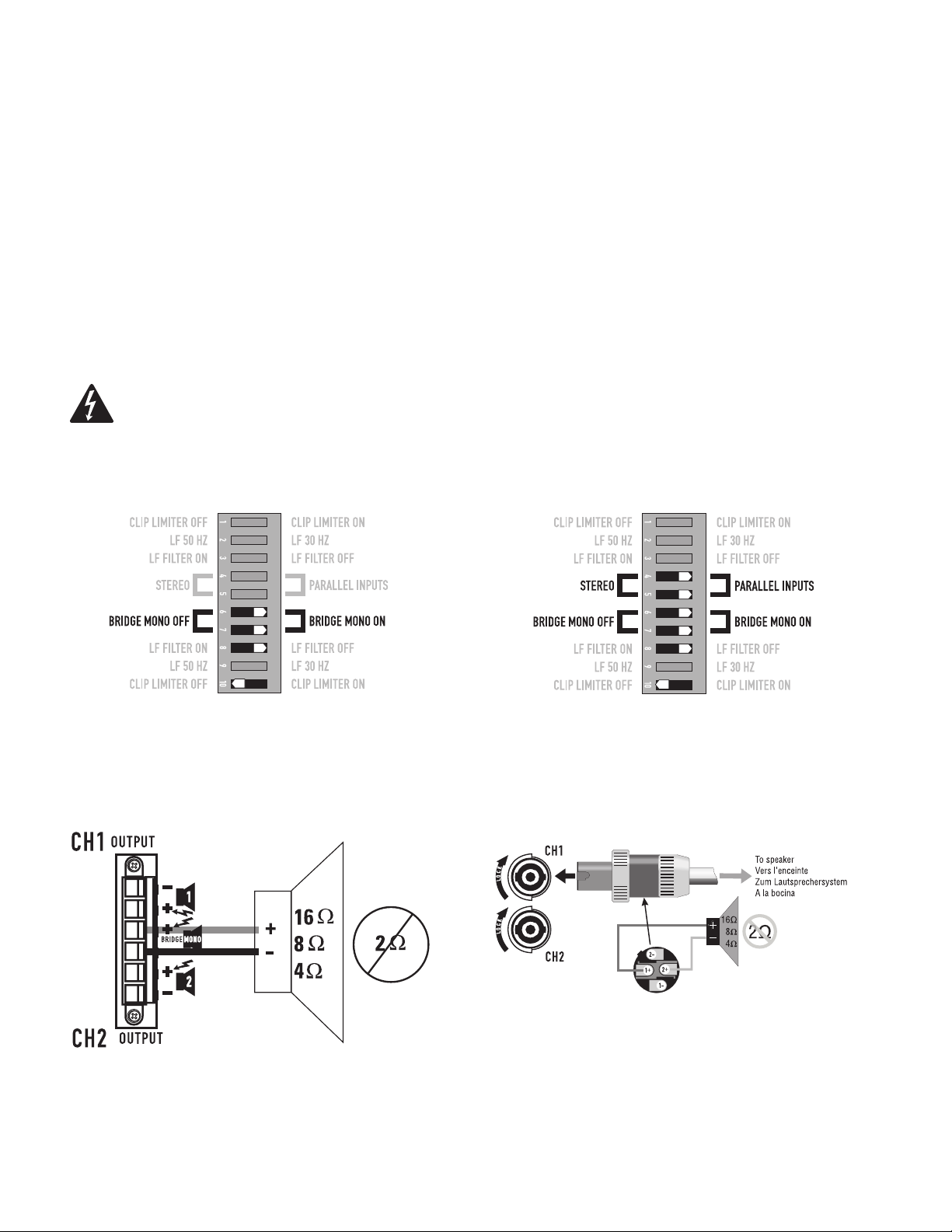
Bridge Mono Mode
What it is
Bridge mono mode combines the power of both amplifier channels into one speaker, resulting in twice the voltage swing, four times the peak
power, and approximately three times the sustained power of a single channel. This mode uses Channel 1's input, attenuation control, input
filter, and clip limiter; Channel 2's dip switch settings should be in the OFF positions, the Attenuation control should be at maximum attenuation
(Figure 13 and Figure 14).
When to use it (or not)
Use Bridge mono to deliver the power of both channels to a single 8 or 4Ω load. Set switch positions 6 and 7 to BRIDGE MONO ON
(Figure 13). Use Channel 1's inputs, and connect the speaker as shown in (Figure 15 and Figure 16).
BRIDGE MONO Precautions
This mode puts a high demand on the amplifier and speaker, Excessive clipping may cause protective muting or speaker damage. Be sure the speaker
has a sufficient power rating.
WARNING: Output voltages greater than 100 volts RMS are present between the bridged terminals of the CMX 2000V. CLASS 3
wiring methods (NEC 1999), as specified in accordance with national and local codes, must be used to connect the speaker.
— Figure 13 —
Channel 2 settings, switches 8 , and 10 are set to off.
— Figure 15 — — Figure 16 —
— Figure 14 —
To patch the signal to additional amplifiers, use
the PARALLEL INPUTS switch settings described
under PARALLEL INPUTS Mode.
To Speaker
9
Page 11
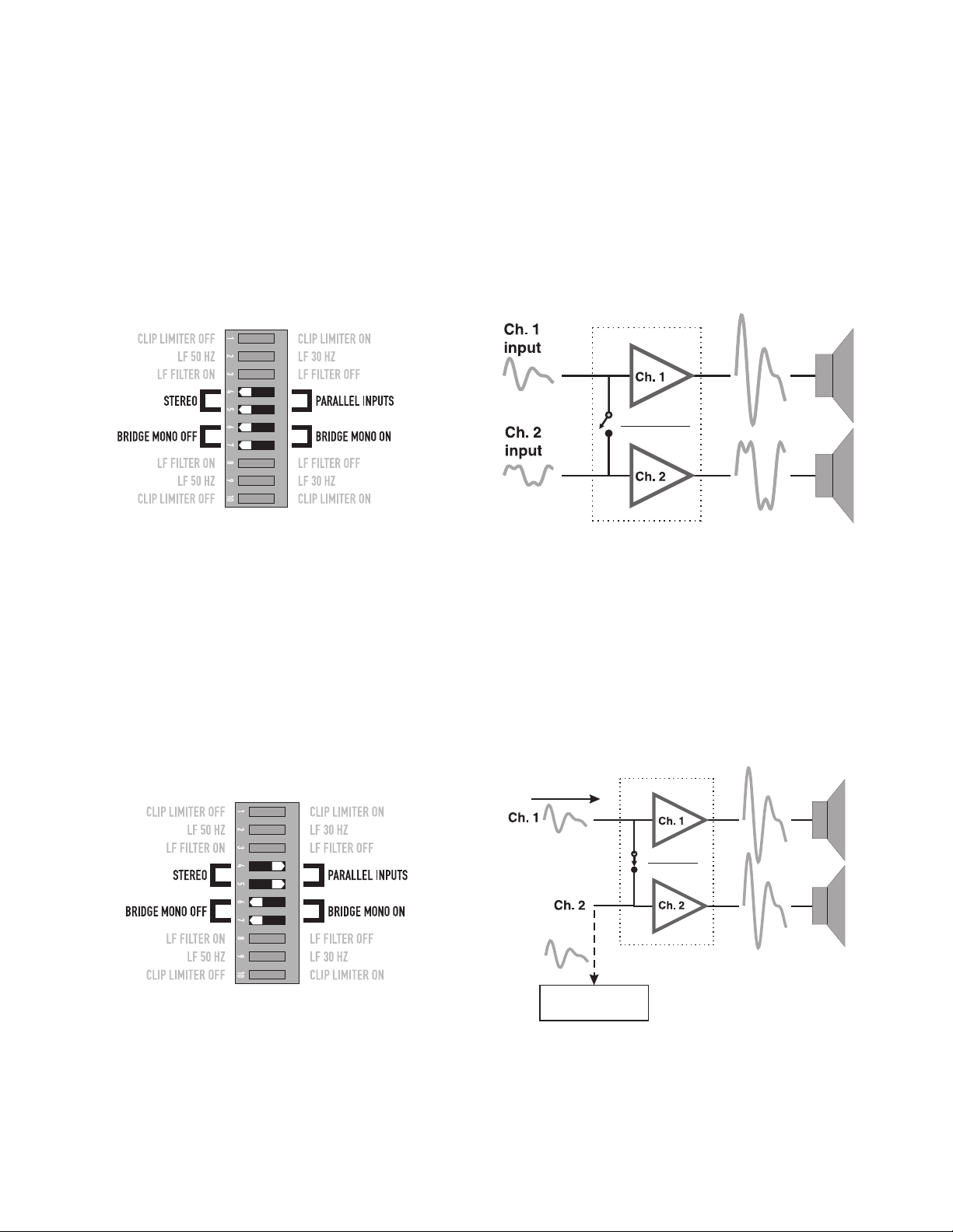
The Difference Between Modes
STEREO Mode
STEREO mode is the typical way of using the amplifier. Each channel is fully independent. Separate signals connect at the inputs, the attenuation knobs
control their respective channels, and separate speakers connect to each output. The dip switches are set as shown in (Figure 17), a schematic illustra-
tion in (Figure 18).
Examples:
• Two-channel (stereo) playback.
• Two independent mono signals, such as main and monitor mixes.
• Bi-amped operation, with the low frequencies in Channel 1 and the highs in Channel 2.
— Figure 17 —
— Figure 18 —
PARALLEL INPUTS Mßode
This mode is similar to the STEREO mode, except that the inputs for Channel 1 and Channel 2 are internally connected together. A signal into
Channel 1 jack drives both channels directly (Figure 19). Use Channel 1 Input, do not connect different sources to both channels. Each channel's
attenuation control still functions as usual, and each channel feeds its own speaker load. The dip switches are set as shown in (Figure 20).
In PARALLEL INPUTS mode, you can patch the input signal on to additional amplifiers by using any of the remaining input jacks.
See Ch 2 in (Figure 19).
Example:
• One mono signal driving both channels, with independent attenuation control for each speaker system.
signal input
NO INPUT!
Can be used to Daisy-chain
additional amplifiers
— Figure 20 —
Amplifier #2
— Figure 19 —
10
Page 12
12
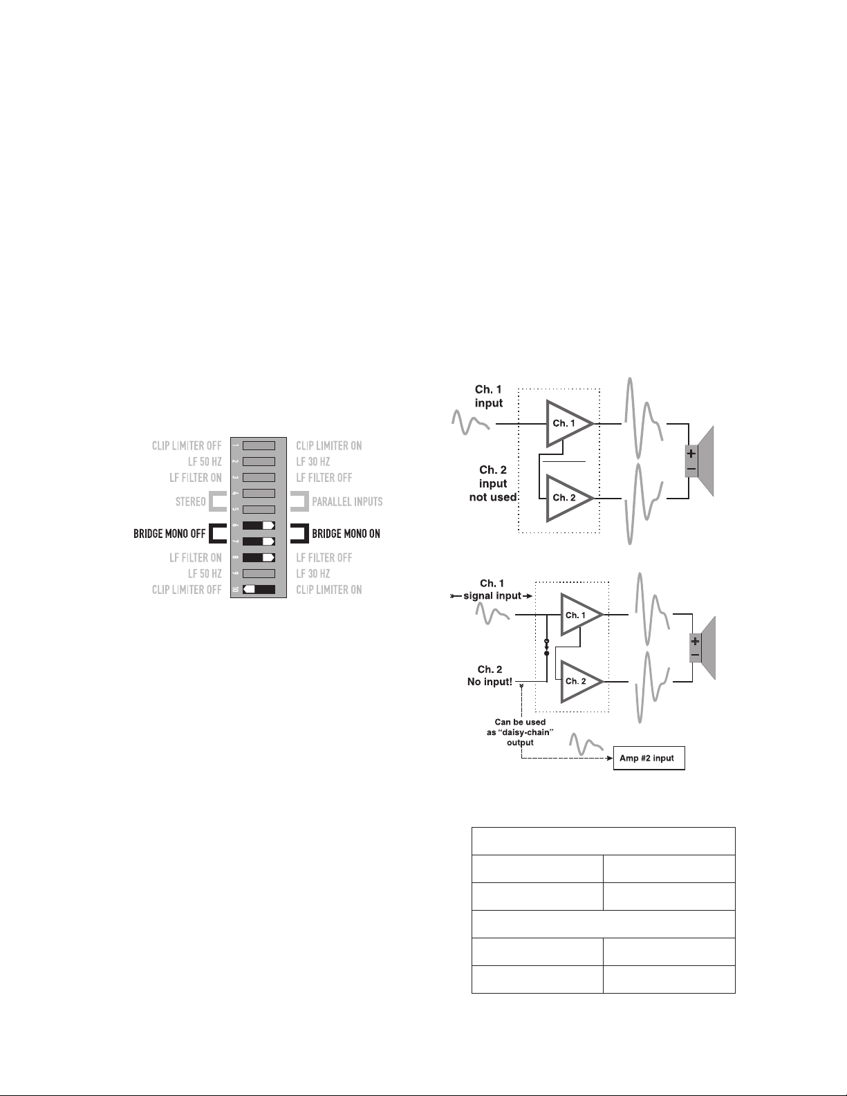
BRIDGE MONO Mode
This mode combines the full power capabilities of both channels into a single speaker system. The amplifier internally re-configures so that both
channels operate as a unit. This delivers double the output voltage, resulting in four times the peak power and three times the sustained power into
a single 8 or 4 ohm speaker load. The BRIDGE MONO mode section on page 9 describes the special speaker connection used. Refer to (Figure 21
through Figure 23).
Examples:
• Driving a single 8 ohm speaker with the combined 4 ohm power of both channels.
• Driving a single 4 ohm speaker with the combined 2 ohm power of both channels.
Precautions
• BRIDGE MONO mode makes it possible to drive thousands of watts into a single speaker. AC current consumption will usually be higher. Avoid
excessive signal level, and make sure the wiring and speaker can handle the power.
• If the load is 4 ohms or less and prolonged overloads occur, the amplifier will probably mute for several seconds during peaks, and the circuit
breaker may trip.
• Do not use 2 ohm loads.
See the additional BRIDGE MONO mode warnings on page 9.
— Figure 21 —
Set Channel 2 dip switches, 8 and 10, to off.
Distributed Constant Voltage Outputs
70 / 100 Volt Operation
The CMX 2000V can operate in 70 Volt or 100 Volt operation in STEREO
mode or BRIDGE MONO mode. Please refer to the above section on
BRIDGE MONO mode for proper setup and configuration. Refer to (Table 2)
for the power outputs of these modes.
— Figure 22 —
— Figure 23 —
STEREO Mode (Both Channels Driven)
70 Volt 2500 W
100 Volt 1000 W
BRIDGE MONO mode
70 Volt 5000 W
11
100 Volt 3600 W
— Table 2 —
Page 13
Connections
Inputs
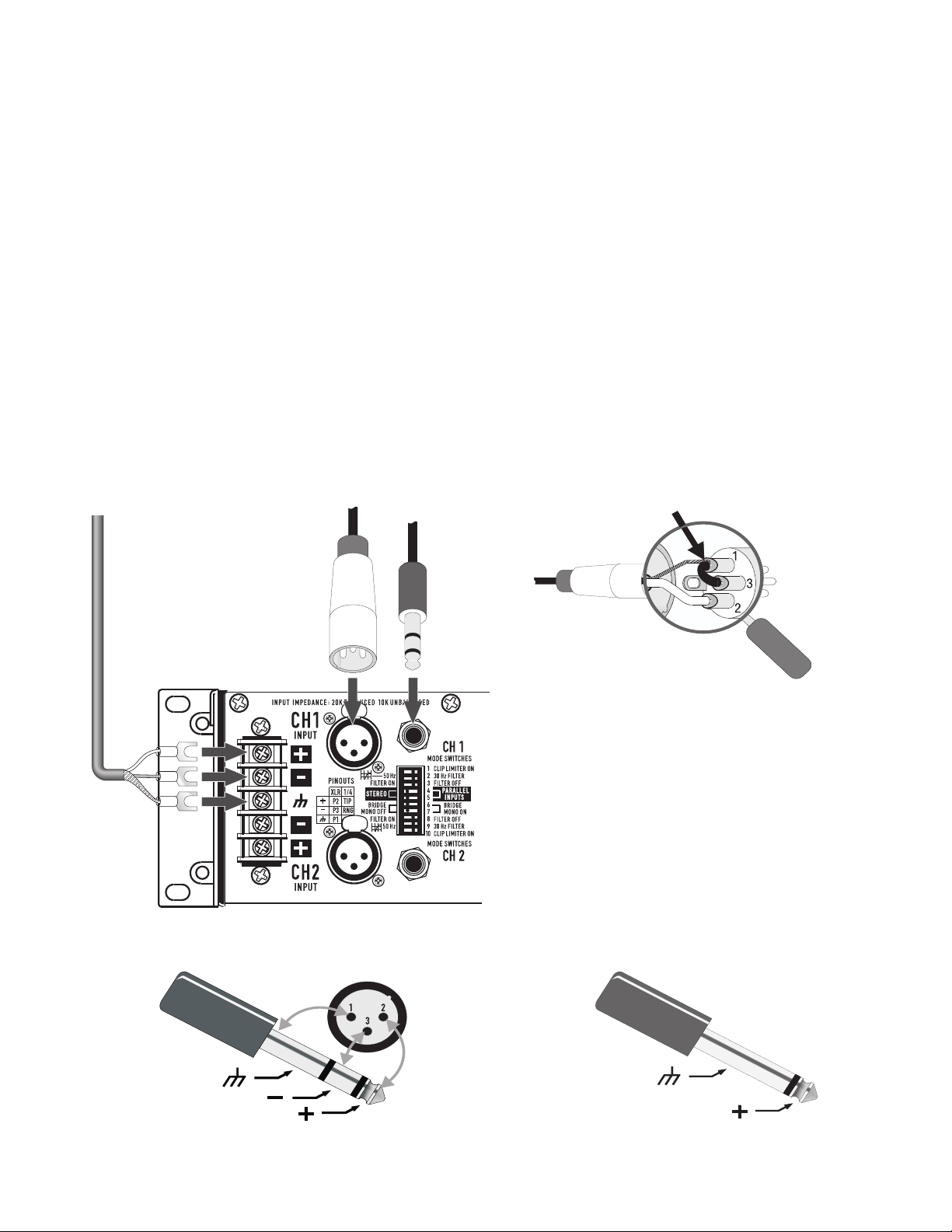
Each channel has active balanced XLR, ¼" (6.3 mm), and Barrier Strip inputs wired in parallel (Figure 24). The input impedance for balanced is
20k ohms, for unbalanced it is 10k ohms
Balanced connections are recommended to reduce AC hum and interference, especially with long cable runs. Unbalanced connections may be suitable for short cables. The signal's source impedance should be less than 600 ohms.
Balanced Inputs
Use the XLR or ¼" (6.3 mm) TRS input jacks, or the barrier strip. (Figure 24)
Unbalanced Inputs:
Connect the unused side (Pin 3) of the balanced input to ground (Pin 1), as shown in (Figure 25).
For STEREO operation, use the inputs for both Channel 1 and Channel 2. For PARALLEL INPUTS or BRIDGE MONO operation, use the
Channel 1 input.
See the section on operating modes for more information. To patch the audio signal to other amplifiers (PARALLEL INPUTS and BRIDGE MONO
modes only), see the instructions for using PARALLEL INPUTS on page 8 through page 11.
XLR unbalanced Jumper pin 1 to
pin 3
Any one of these
three connections
— Figure 24 —
Balanced
Pin 1 = Ground
Pin 2 = +
Pin 3 = —
— Figure 25 —
Unbalance
ground
inverting input
non‑inverting input
— Figure 26 —
ground
non‑inverting input
— Figure 27 —
12
Page 14
14
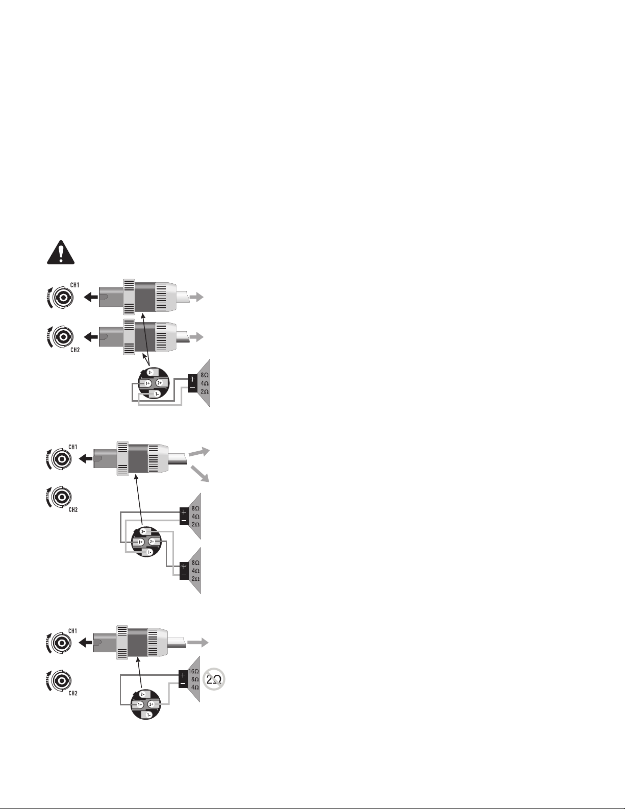
Speakon™ Outputs
CMX amplifiers offer a choice of output connections, with two NL4MD Speakon™ jacks and a terminal block connector. (Figure 28 through Figure
30)
The Speakon™ connector is designed specially for high-power speaker connections. It locks in place, prevents shock hazard, and assures the
correct polarity.
Each channel accepts a normal two-wire cable. In addition, Channel 1 accepts a four-wire cable. Channel 1 Speakon™ jack has both Channel 1 and
Channel 2 output signals (Figure 29), so it is especially useful for PARALLEL INPUTS, bi-amp, or BRIDGE MONO operation (see BRIDGE MONO
operating precautions on page 9). Channel 2 Speakon™ carries only the output from Channel 2.
For easier insertion, use the newer-style NL4FC Speakon™ connectors with quick-lock thumb latches.
Speaker Cabling
Larger wire sizes and shorter lengths minimize both loss of power and degradation of damping factor. Do not place speaker cables next to
input wiring.
WARNING: To prevent electric shock, do not operate the amplifier with any of the conductor of the speaker wire exposed.
To Channel 1 speaker
— Figure 28 —
— Figure 29 —
To Channel 2 speaker
To Channel 1 speaker
To Channel 2 speaker
Channel 1
Channel 2
Two channels, two Speakon™ connectors using two wires each.
(STEREO, bi‑amp, or PARALLEL INPUTS mode)
Two channels, one Speakon™ connector using four wires
(STEREO, bi‑amp, or PARALLEL INPUTS mode)
— Figure 30 —
To speaker
BRIDGE MONO MODE
13
Page 15
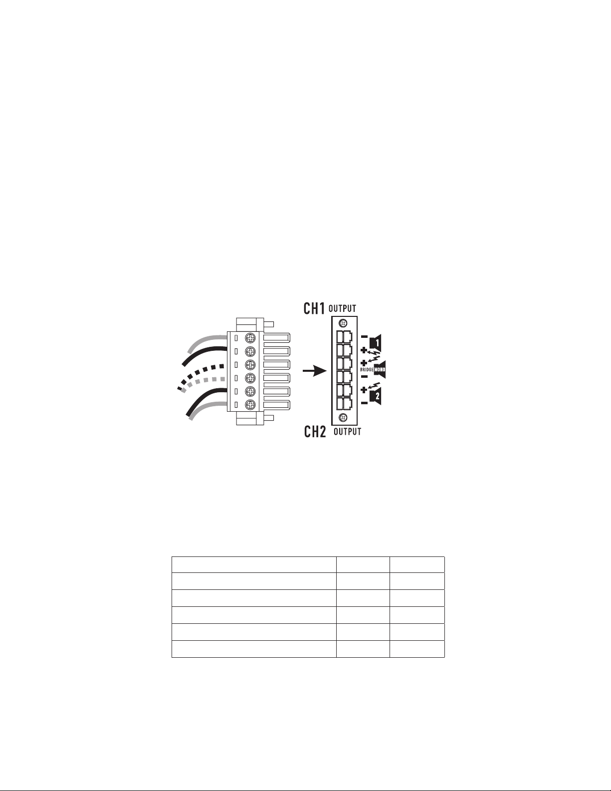
Terminal Block Connector
The terminal block connector requires the following assembly.
1. Strip the wires to 7 ~ 8 mm.
2. Insert the wires into the male part of the connector according to the operating mode you are using. See (Figure 31).
3. Use a flat-tip screwdriver to secure the wires. Tighten the screws to 6 in.-lbs.
4. Insert the plug into the receptacle on the amplifier.
5. Use a flat-tip screwdriver to secure the connector. Tighten the screws to 6 in.-lbs.
STEREO and PARALLEL INPUTS mode:
Wire as shown by loudspeaker symbols 1 and 2 on the back of the amplifier, and as shown by the solid wires in the diagram.
BRIDGE MONO mode:
Wire as shown by BRIDGE MONO loudspeaker symbol on the amplifier, and as shown by the dashed wires in (Figure 31).
— Figure 31 —
Terminal Block Connector Wiring
Wire range - 6 mm
Solid wire (AWG) 28 – 10 -
2
Stranded wire (AWG/mm
Torque (lb.-in.) 6 -
Wire strip length 7 – 8 mm -
) 28 – 10 -
UL IEC
— Table 3 —
2
14
Page 16
16
Operation
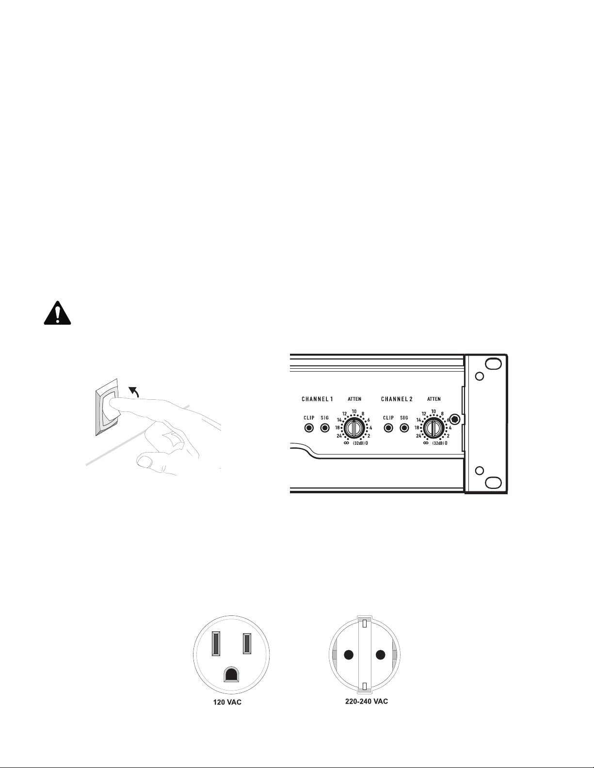
AC Power Switch
Before applying power, check all connections and turn the attenuation controls fully counter clockwise to maximum attenuation.
One second of muting is normal when the amplifier is turned on or off (Figure 32).
Attenuation Controls
Turn the Attenuation controls clockwise to decrease Attenuation and counterclockwise to increase Attenuation.
The Attenuation controls are marked in numeric increments from ∞ to 0 (clockwise) indicating the amount of attenuation. Settings should normally
be made within the lower attenuation range. The range above 14 on the attenuation scale should not be used for normal program levels, as the
input headroom could be exceeded, but can be used for testing at reduced gain levels. At the maximum attenuation setting (∞), the signal is completely cut off (Figure 33).
The maximum Voltage Gain for the CMX 2000V is 31.6 x (30 dB).
LED Indicators
The green SIGNAL LED indicators light at approximately 0.1% of full power.
The red CLIP LED indicator flashes during overload (clipping).
CAUTION: Continuous operation at high power may trigger the thermal protection circuitry, shutting down the amplifier and fully
illuminating the Protect indicator. Operation will resume after the amplifier has cooled down sufficiently. If both rear panel circuit
breakers are tripped, the Protect indicator will not be illuminated. See the Troubleshooting on page <OT>.
On
— Figure 32 —
— Figure 33 —
Operating Voltage
(AC Mains)
Make sure you connect the amplifier to the correct AC line voltage, as shown on the serial number label. Connecting to the wrong line voltage is
dangerous and may damage the amplifier.
The power requirements are 100, 120, 230 VAC, 50-60 Hz
— Figure 34 —
15
Page 17
Fan Cooling
The fan speed varies automatically to maintain safe internal temperatures. Keep the front and rear vents clear to allow full air flow. Hot air exhausts
out the front of the amplifier so it does not heat the interior of the rack. Make sure that plenty of cool air can enter the rack, especially if there are
other units which exhaust hot air into it. See (Figure 35).
Safe Operating Levels
The amplifiers protective muting system guards against excessive internal temperatures. With normal ventilation and 4 to 8 ohm loads, the amplifier
will handle any signal level including overdrive-but make sure that the speakers can handle the full power! However, lower load impedances and
higher signal levels produce more internal heating. Into 2 ohm loads, frequent or prolonged clipping (indicated by constant flashing of the red CLIP
LED) may trigger protective muting. Bridge mono mode doubles the output impedance of the amp; 4 ohms is the minimum load impedance. Heavy
clipping may cause muting. If this happens, refer to the Troubleshooting, section.
Warm air exits the amplifier
and rack.
— Figure 35 —
Troubleshooting
Problem: No Sound
Indication: POWER indicator not lit
Check the AC plug. Also check the circuit breaker on the rear panel.
Confirm that the AC outlet works by plugging in another device. If too many
amplifiers are used on one outlet, the building’s circuit breaker may trip and shut
off power.
An overload in Bridged Mono mode may cause the amplifier to click off
for several seconds. Check the load impedance (4Ω minimum), or reduce
signal level.
An amplifier which keeps shutting off may have a serious internal fault. Turn it
off, remove AC power, and have the amplifier serviced by a qualified technician.
Cool air enters the amplifier
and rack.
Indication: SIGNAL LED responding to signal level
If the green SIGNAL indicators are lighting normally, the fault is somewhere
between the amp and the speaker. Check the speaker wiring for breaks. Try
another speaker and cable.
Indication: SIGNAL LED not lit
If the green POWER indicator LED is lit and the fan is running, yet the signal
LEDs indicate no signal, check the input. Make sure the signal source is operating
and try another input cable. Connect the source to another channel or amplifier
to confirm its operation.
16
Page 18
18
Indication: CLIP LED flashing
If the red CLIP indicator flashes when signal is applied, the amplifier output may be
shorted. Check the speaker wiring for stray strands or breaks in the insulation.
Indication: CLIP LEDs bright and steady
The amplifier is in protective muting.
One second of muting is normal when the amp is turned on or off.
Overheating will cause protective muting. The fan will be running at full speed and the
chassis will be hot to the touch; sound should resume within a minute as the amplifier
cools to a safe operating temperature. Check for proper ventilation. If the fan isn’t running
at all, the amplifier requires servicing.
Problem: Distorted Sound
Indication: CLIP LED flashing
If the red CLIP indicator flashes before the signal indicator does, the load impedance is
abnormally low or shorted. Unplug each speaker one-by-one at the amplifier. If the CLIP
LED goes out when you disconnect a cable, that cable or speaker is shorted. Try another
cable and speaker to locate the fault.
Indication: CLIP LED not flashing
This could be caused by a faulty speaker or loose connection. Check the wiring and try
another speaker.
The signal source may be clipping. Keep the amplifier attenuation controls at mid point so
that the source does not have to be overdriven.
Problem: No channel separation
Check the switch settings on the back of the amplifier. Make sure the “Parallel Input” and
“BRIDGE MONO” switches are OFF in dual-channel, bi-amp, or stereo use where different
signals go to each channel.
Make sure other equipment in the signal path, such as mixers, preamps, etc., are set for
stereo, not mono.
Problem: Hum
Move cabling and signal sources to identify “hot spots” in the system. Cables with faulty
shielding are a frequent entry point for hum.
Problem: Hiss
Unplug the amplifier input to confirm that the hiss is coming from the source or a device
upstream; erratic or popping noises indicate an electronic fault in the offending unit.
To keep the normal noise floor low, operate the primary signal source at full level, without
clipping, and avoid boosting the signal further between the source and the amplifier.
Problem: Squeals and feedback
Microphone feedback should be controlled with mixer controls. If noise continues to build
up with zero mic gain, there is a serious fault in the signal processors or cables. Working
in succession from the signal source towards the amplifier, check each device in the signal
path by reducing its gain or unplugging it.
17
Page 19

Specifications
CMX 2000V
Stereo Mode (both channels driven)
8Ω / FTC 20 Hz - 20 kHz / 0.1% THD
8Ω / EIA 1 KHZ / 0.1% THD
4Ω / FTC 20 HZ - 20 KHZ / 0.1% THD
4Ω / EIA 1 KHZ / 1% THD
2Ω / EIA 1 KHZ / 1% THD
70 V - Direct drive / EIA 1 kHz / 1% THD
100 V - Direct drive / EIA 1 kHz / 1% THD
Bridge Mono Mode
8Ω / FTC 20 Hz - 20 kHz / 0.1%THD
8Ω / EIA 1 kHz / 0.1%THD
4Ω / EIA 1 kHz / 1%THD
140 V - Direct drive / EIA 1 kHz / 1% THD
100 V - Direct drive / EIA 1 kHz / 1% THD
Distortion (SMPTE-IM) < 0.01%
Signal to Noise (20 Hz – 20 kHz) 8Ω > -100 dB
Input Sensitivity 8Ω 1.42 V (+5.3 dBu)
Voltage Gain (8Ω) 36 dB
Output Circuitry 3-tier Class H
Power Requirements
Typical, 1/8 power, pink noise at 4Ω
120 VAC
230 VAC
Severe, 1/3 power pink noise at 4Ω
120 VAC
230 VAC
Frequency Response 20 Hz – 20 kHz, +/- 1 dB dB -3 dB points: 5 Hz and 50 kHz (LF filter bypassed / 8Ω)
Damping Factor > 300 at 8Ω
Input Impedance (Ω) 10 kΩ unbalanced / 20 kΩ balanced
Input Clipping 6.4 Vrms (+18 dBu)
Cooling Continuously variable speed fan, back-to-front air flow
Connectors (each channel) Input: Active balanced; barrier strip, XLR and 1/4" (6.3 mm) - TRS tip and XLR
Controls Front: AC Switch, Channel 1 and Channel 2 gain knobs
Indicators Power-on: Green LED / Signal: Green LED (1 per channel) / Clip: Red LED
Amplifier Protection Stable into reactive or mismatched loads
Load Protection On/off muting, triac crowbar on each channel
Dimensions (HWD) 5.25" (3RU) x 19" x 15.9" (133 mm x 483 mm x 400 mm)
Weight - Net / Shipping 75 lb (34 kg) / 87 lb (39.5 kg)
1050 W
1100 W
1600 W
2000 W
2500 W
2500 W
1000 W
3200 W
3600 W
5000 W
5000 W
3600 W
13.9 A
7 A
26.9 A
13.5 A
(pin 2 positive)
Output: Detachable terminal block and Speakon™
Rear: 10-position DIP switch
(1 per channel)
Specifications subject to change without notice.
18
Page 20

Mailing Address:
QSC Audio Products, LLC
1675 MacArthur Boulevard
Costa Mesa, CA 92626-1468 USA
Telephone Numbers:
Main Number: (714) 754-6175
Sales & Marketing: (714) 957-7100 or toll free (USA only) (800) 854-4079
Customer Service: (714) 957-7150 or toll free (USA only) (800) 772-2834
Facsimile Numbers:
Sales & Marketing FAX: (714) 754-6174
Customer Service FAX: (714) 754-6173
World Wide Web:
www.qscaudio.com
E-mail:
info@qscaudio.com
service@qscaudio.com
© 2010 QSC Audio Products, LLC. All rights reserved. QSC and the QSC logo are registered trademarks of QSC Audio Products, LLC in the U.S. Patent and Trademark office and other countries.
Speakon is a trademark of Neutrik. All other trademarks are the property of their respective owners. Patents may apply or be pending.
Page 21

Série CMX
Manuel d'utilisation
Amplificateur CMX 2000V
TD‑000323‑00
*TD‑000323‑00*
Page 22
2
PRÉCAUTIONS IMPORTANTES ET EXPLICATION DES SYMBOLES
AVERTISSEMENT !
L'éclair fléché situé dans un triangle équilatéral a pour objet de signaler à l'utilisateur la présence d'une tension « dangereuse » non
isolée dans le boîtier du produit suffisante pour présenter un risque d'électrocution pour l'homme.
Le point d'exclamation dans un triangle équilatéral a pour objet de signaler à l'utilisateur la présence d'instructions importantes
d'utilisation et de maintenance (réparation) dans ce manuel.
1. Lire ces instructions.
2. Conserver ces instructions.
3. Respecter tous les avertissements.
4. Suivre toutes les instructions.
AVERTISSEMENT : Pour écarter les risques d'incendie et d'électrocution, ne pas exposer ce matériel à la pluie ou l'humidité. Ne pas
utiliser cet appareil près de l'eau.
5. Nettoyer uniquement avec un chiffon sec.
6. Prévoir un dégagement minimum de 152 mm à l'arrière de l'enceinte pour un refroidissement par convection. Tout ce qui risquerait de
réduire la circulation d'air doit être tenu à l'écart de l'arrière de l'enceinte (rideaux, tissu, etc.). Ne pas bloquer les bouches d'aération. Ce
produit est un amplificateur de puissance qui dégage de la chaleur.
7. N'installer à proximité d'aucune source de chaleur comme des radiateurs, des registres de chaleur, des poêles ou d'autres appareils (y
compris des amplis) qui dégagent de la chaleur.
8. Ne pas éliminer la sécurité de la fiche de terre du câble d'alimentation de style Edison à 3 broches. Une fiche de terre a deux broches
et une broche de terre. La troisième broche assure la sécurité. Si la fiche fournie n'entre pas dans la prise, consulter un électricien pour
faire remplacer la prise obsolète. Ne pas couper la fiche de terre et ne pas utiliser d'adaptateur qui rompe le circuit de mise à la terre. Par
mesure de sécurité, cet appareil doit être correctement mis à la terre.
9. Protéger le cordon d'alimentation pour que personne ne puisse marcher dessus, qu'il ne puisse pas être pincé, surtout les fiches, les prises
de courant d'entretien et le point d'émergence du cordon de l'appareil.
10. Le coupleur de l'appareil est l'interrupteur général et il doit être immédiatement utilisable après l'installation.
11. Utiliser uniquement les accessoires spécifiés par QSC Audio Products, LLC.
12. Utiliser uniquement avec la visserie, les supports, socles et composants vendus avec l'appareil ou par QSC Audio Products, LLC.
13. Débrancher l'appareil en cas d'orage électrique ou lorsqu'il est inutilisé pendant longtemps.
14. Confier toutes les réparations à un personnel qualifié. Une réparation s'impose lorsque l'appareil a été endommagé d'une manière
quelconque, par exemple endommagement du cordon d'alimentation ou de sa fiche, déversement de liquide ou chute d'objets sur ou à
l'intérieur de l'appareil, exposition de l'appareil à la pluie ou l'humidité, fonctionnement anormal ou chute de l'appareil.
15. L'appareil ne doit pas être exposé à des gouttes ou des projections et aucun objet rempli de liquide (vase, par ex.) ne doit être
posé dessus.
1
Page 23

Garantie (États-Unis seulement ; dans les autres pays, consulter le revendeur
ou le distributeur)
Avis de non-responsabilité
QSC Audio Products, LLC n’est pas responsable des dommages subis par les amplificateurs ou tout autre équipement causé par un acte de négligence
ou une installation impropre et/ou l’utilisation de ce haut-parleur.
QSC Audio Products – garantie limitée de 3 ans
QSC Audio Products, LLC (« QSC ») garantit que ses produits sont dépourvus de tout vice de fabrication et/ou de matériel pendant une période de trois
(3) ans à partir de la date de vente et remplacera les pièces défectueuses et réparera les produits qui fonctionnent mal dans le cadre de cette garantie si
le défaut survient dans des conditions normales d'installation et d'utilisation - à condition que l'appareil soit retourné à l'usine ou à l'un de nos centres de
réparation agréés en port pré-payé, accompagné d'un justificatif d'achat (facture, par ex.). Cette garantie prévoit que l'examen du produit retourné doit
indiquer, selon notre jugement, un défaut de fabrication. Cette garantie ne s'étend à aucun produit qui a été soumis à une utilisation abusive, un acte de
négligence, un accident, une installation incorrecte ou un produit dont le code-date a été retiré ou effacé. QSC ne pourra être tenue pour responsable de
dommages accessoires et/ou indirects. Cette garantie vous accorde des droits spécifiques. Cette garantie limitée est librement cessible durant sa période
de validité. Le client pourra bénéficier d'autres droits, variables d'une juridiction à l'autre.
Si ce produit a été fabriqué pour une exportation et une vente en dehors des États-Unis ou de ses territoires, cette garantie limitée ne s'appliquera
pas. Le retrait du numéro de série sur ce produit ou l’achat de ce produit auprès d’un revendeur non agréé annulera cette garantie limitée. Cette
garantie est régulièrement mise à jour. Pour obtenir la toute dernière version de la garantie de QSC, aller sur le site www.qscaudio.com. Nous contacter
au 800-854-4079 ou visiter notre site Web www.qscaudio.com.
© Copyright 2010, QSC Audio Products, LLC
QSC est une marque déposée de QSC Audio Products, LLC.
QSC et le logo QSC sont des marques déposées auprès de l'U.S. Patent and Trademark Office.
Toutes les marques de commerce appartiennent à leur propriétaire respectif.
2
Page 24
4
Introduction
Merci d’avoir acheté cet amplificateur QSC. Prière de lire les instructions suivantes pour obtenir les meilleurs résultats. L'amplificateur 3RU à deux
canaux refroidis par ventilateur robuste est un gage de haute performance et de puissance dans un châssis compact solide.
Caractéristiques
• Limiteurs d’amplitude indépendants désactivables par l'utilisateur
• Filtre basses fréquences entièrement sélectionnable ; choix d'affaiblissement 30 ou 50 Hz
• Modes STEREO (deux canaux), PARALLEL INPUTS (entrées parallèles) ou BRIDGE MONO (mono pont)
• Entrées équilibrées — XLR, TRS 6,3 mm et bornier à cloisons
• Bornier enfichable et sorties Speakon™
• Boutons d'atténuation à 21 crans
• Voyants du le panneau avant - alimentation, signal et limiteur
• Plaque de sécurité de commande d'atténuation
— Figure 1 —
Mode STEREO (deux canaux pilotés)
FTC : 20 Hz – 20 kHz à taux
d'harmonique (THD) 0,1 %
8 ohms par canal 1 050 W
4 ohms par canal 1 600 W
EIA : 1 kHz à THD 1 %
8 ohms par canal 1 100 W (THD 0,1 %)
4 ohms par canal 2 000 W
2 ohms par canal 2 500 W
70 V - Pilotage direct 2 500 W
100 V - Pilotage direct 1 000 W
Mode BRIDGE MONO
FTC : 20 Hz – 20 kHz THD 0,1 %
8 ohms 3 200 W
EIA : 1 kHz à THD 1 %
8 ohms 3 600 W
4 ohms 5000 W (THD 0,1 %)
140 V - Pilotage direct 5 000 W
100 V - Pilotage direct 3 600 W
– Tableau 1 –
3
Page 25
Déballage
Le carton préparé en usine contient les éléments suivants :
• Amplificateur CMX
• Manuel d’utilisation
• Pieds en caoutchouc adhésifs (pour applications de montage sans bâti)
• Plaque de sécurité d'atténuation
• Kit de pattes de fixation pour bâti arrière
• Cordon d'alimentation détachable type CEI
Utiliser le même type de carton pour renvoyer l’amplificateur.
Installation sur bâti
Utiliser quatre vis et rondelles pour installer l’amplificateur aux coulisses à équipement du bâti. Pour utiliser l'amplificateur en dehors d'un bâti,
attacher les pieds en caoutchouc auto-adhésifs en dessous. Utiliser le kit de pattes pour bâti arrière pour soutenir l’arrière de l’amplificateur en vue
d’une utilisation portable. Pour planifier, voir la figure 2.
ligne centrale verticale des trous à 10,2 cm
du bord arrière
trou = 6,4 mm x 11,9 mm
3.00" (7.6 cm)
rainure de 1 cm (hauteur) x
1,2 cm (profondeur)
2.25" (5.7 cm)
2.60" (66 mm)
17.40" (442 mm)
— Figure 2 —
15.8" (402 mm)
14.8" (375 mm)
5.2" (132 mm)
2.25" (57 mm)
18.90" (482 mm)
4
Page 26
6
1 1
2
3
44
5
6
5
7
7
8
9
10 11
1
2
3
4
5 6
Panneau avant (Figure 3)
1. Bouches d'aération
2. Voyant d'alimentation (POWER)
3. Interrupteur de marche/arrêt
4. Commandes d'atténuation
5. Voyants limiteur (CLIP) et signal (SIG)
6. Voyant de mode Protection (PROTECT)
7. Vis de plaque de sécurité
— Figure 3 —
Panneau arrière
1. Connecteurs d'entrée de bornier à cloisons
2. Connecteurs d'entrée XLR
3. Connecteurs d'entrée TRS (6 mm)
4. Commutateur de mode et réglages
5. Bouches d'arrivée d'air de refroidissement
6. Connecteurs de sortie Speakon™
7. Connecteur de bornier
8. Disjoncteurs ~
9. Réglages des commutateurs de mode PARALLEL INPUTS, STEREO,
BRIDGE MONO
10. Étiquette de numéro de série
11. Entrée d'alimentation CEI (connecteur du cordon d'alimentation)
— Figure 4 —
5
Page 27
Fonctions et configuration
Plaque de sécurité de commande d'atténuation
La plaque de sécurité de commande d'atténuation (Figure 5) fournit une protection contre la modification accidentelle des réglages de commande
d'atténuation sur la face de l'amplificateur.
Attacher la plaque, après avoir apporté les derniers réglages aux commandes d'atténuation, en glissant les onglets dans les deux fentes d'installation.
Fixer en place avec la vis.
Fentes d'installation de la
plaque d'atténuation (2)
Plaque d'atténuation non installée
Plaque d'atténuation
Vis de fixation de la
plaque d'atténuation
Plaque d'atténuation installée
— Figure 5 —
Réglage des commutateurs de mode
Le CMX 2000V a des commutateurs de mode PARALLEL INPUTS (ENTRÉES PARALLÈLES), STEREO, BRIDGE MONO (MONO PONT). Chaque canal a
un limiteur d'amplitude et un filtre basses fréquences indépendants.
Limiteur d’amplitude
Définition
Quand le signal audio pilote le circuit de sortie de l'amplificateur au-delà de sa capacité de puissance, il se produit un écrêtage qui aplatit les crêtes de
la courbe. Le limiteur d'amplitude détecte ceci et réduit le gain pour minimiser le degré de surcharge. Pour préserver au maximum la dynamique du
programme, l'écrêtage réduit le niveau de programme moyen juste en dessous du niveau d'écrêtage.
Le limiteur répond uniquement à une limitation réelle et compense automatiquement les variations de charge et de tension. Chaque canal a son
propre limiteur d'amplitude, indépendamment activable ou désactivable, comme illustré à la figure 6.
Quand l'utiliser (ou non)
Lors du pilotage de haut-parleurs pleine gamme, l'écrêtage réduit la distorsion des ondes HF causée par les surcharges en graves. Il protège aussi les
étages d'attaque HF contre une surcharge excessive et l'écrêtage désagréable des harmoniques.
Lors du pilotage de caissons d'extrêmes graves, certains utilisateurs laissent l'amplificateur écrêter sans limiter pour qu'il donne un coup de boost aux
grosses caisses et sons similaires.
ATTENTION : Dans les systèmes à deux amplificateurs, une limitation excessive affectera l'équilibre des fréquences.
— Figure 6 —
6
Page 28

8
Filtre de basses fréquences d'entrée
Définition
Le filtre basse fréquences (LF) affaiblit les signaux en dessous de 30 Hz ou de 50 Hz (Figure 9 et Figure 10). Chaque canal a un filtre basses
fréquence de 12 dB par octave pour éviter la course excessive de la membrane et pour plus de puissance disponible pour la gamme de fréquences
nominale du haut-parleur. Ceci réduit la distorsion et empêche la surcharge de l’amplificateur.
Les réglages de filtre des canaux se font individuellement via les commutateurs DIP illustrés à la figure 7. Quand le filtre est désactivé (Figure 8), un
affaiblissement de 5 Hz protège contre les entrées (-) ou infrasonores profondes.
Quand l'utiliser (ou non)
En règle générale, vos haut-parleurs donneront un meilleur son avec un filtrage adéquat. Sauf si vous avez déjà un filtre dans un appareil précédent,
faire correspondre le réglage à la basse fréquence nominale de vos haut-parleurs. Les haut-parleurs à évent (bass-reflex, résonnant, etc.) sont surtout
sensibles à une course excessive de la membrane à des fréquences inférieures à leur limite nominale.
Le filtre 50 Hz fonctionne bien avec la plupart des haut-parleurs pleine gamme compacts avec un léger boost à 100 Hz en complément. Le filtre de
30 Hz est destiné aux caissons d'extrêmes graves et grandes enceintes pleine gamme. La position LF FILTER OFF est réservée aux applications telles
que la surveillance du playback en studio, où vous devez savoir si des signaux infrasonores indésirables sont présents dans votre mixage.
— Figure 7 —
— Figure 8 —
— Figure 9 —
— Figure 10 —
7
Page 29
Mode PARALLEL INPUTS (Entrées parallèles)
Définition
Les commutateurs PARALLEL INPUTS vous permettent d'utiliser l'amplificateur en mode parallèle, délivrant le même signal aux deux canaux sans
câble Y. Chaque canal pilote la charge de son propre haut-parleur, avec gain, filtrage et limitation d'amplitude indépendants.
Régler les commutateurs PARALLEL INPUTS sur 4 et 5 pour coupler les entrées (Figure 11). Tourner les commutateurs sur STEREO pour un mode
stéréo, bi-ampli ou autre mode à 2 canaux.
En mode PARALLEL INPUTS, vous pouvez utiliser l'autre jeu de connecteurs d'entrée pour transporter le signal aux autres amplificateurs (Figure 12).
On parle souvent de connexion en guirlande.
Quand l'utiliser
Utiliser le mode PARALLEL INPUTS pour piloter les deux haut-parleurs avec un signal d'entrée. Ceci permet de maintenir les commandes de gain,
filtrage et limitation séparées.
Remarque : Si un signal équilibré est utilisé, utiliser uniquement des câbles équilibrés ; un câble non équilibré suffira à lui seul à déséquilibrer toute la
chaîne du signal, causant éventuellement un ronflement.
Remarque : Désactiver les commutateurs PARALLEL INPUTS en alimentant l'ampli avec deux signaux séparés.
— Figure 11 —
— Figure 12 —
8
Page 30

10
Mode Bridge Mono (Mono pont)
Définition
Le mode Bridge Mono combine la puissance des deux canaux d'amplificateur en un haut-parleur, donnant deux fois l'excursion de tension, quatre fois
la puissance maximale et environ trois fois la puissance soutenue d'un canal unique. Ce mode utilise l'entrée du canal 1, la commande d'atténuation,
le filtre d'entrée et le limiteur d'amplitude ; les commutateurs DIP du canal 2 doivent être sur OFF, la commande d'atténuation doit être au réglage
maximum (Figure 13 et Figure 14).
Quand l'utiliser (ou non)
Utiliser le mode Bridge Mono pour délivrer la puissance des deux canaux en une charge unique de 8 ou 4 Ω. Régler les commutateurs aux positions 6
and 7 sur BRIDGE MONO ON (Figure 13). Utiliser les entrées du canal 1 et brancher le haut-parleur comme indiqué à la figure 15 et à la figure 16.
Précautions liées au mode BRIDGE MONO
Ce mode sollicite fortement l'amplificateur et le haut-parleur. Un écrêtage excessif peut causer une sourdine de protection ou l'endommagement du
haut-parleur. S'assurer que le haut-parleur affiche une puissance nominale suffisante.
AVERTISSEMENT : Des tensions de sortie supérieures à 100 volts RMS sont présentes entre les bornes pontées du CMX 2000V.
Les méthodes de câblage CLASS 3 (NEC 1999), conformément aux codes locaux et nationaux, doivent être utilisées pour brancher
le haut-parleur.
— Figure 13 —
Les réglages du canal 2, commutateurs 8 et 10, sont
sur OFF
— Figure 15 — — Figure 16 —
— Figure 14 —
Pour relier le signal à des amplificateurs
supplémentaires, utiliser les réglages
PARALLEL INPUTS décrits sous « Mode
PARALLEL INPUTS (entrées parallèles) ».
Vers le haut‑
parleur
9
Page 31

Différence entre les modes
Mode STEREO
Le mode STEREO est la mode d'utilisation typique de l'amplificateur. Chaque canal est entièrement indépendant. Des signaux séparés sont
connectés aux entrées, les boutons d'atténuation commandent leur canal respectif et des haut-parleurs séparés sont branchés sur chaque sortie. Les
commutateurs DIP sont réglés comme illustré (Figure 17 et Figure 18).
Exemples :
• Playback à deux canaux (stéréo).
• Deux signaux mono indépendants - principal ou surveillance des mixages, par exemple.
• Fonctionnement bi-ampli, avec les basses fréquences au canal 1 et les hautes fréquences au canal 2.
— Figure 17 —
— Figure 18 —
Mode PARALLEL INPUTS (Entrées parallèles)
Ce mode est similaire au mode STEREO, à ceci près que les entrées du canal 1 et du canal 2 sont interconnectées. Un signal dans la prise du canal
1 pilote directement les deux canaux (Figure 19). Utiliser l'entrée du canal 1 ; ne pas brancher différentes sources aux deux canaux. La commande
d'atténuation de chaque canal fonctionne toujours comme d'habitude et chaque canal alimente la charge de son propre haut-parleur. Les
commutateurs DIP sont réglés comme illustré (Figure 20).
En mode PARALLEL INPUTS, vous pouvez relier le signal d'entrée à tout amplificateur supplémentaire en utilisant l'une des prises d'entrée restantes.
Voir Ch 2 à la figure 19.
Exemple :
• Un signal mono pilotant les deux canaux, avec commande d'atténuation indépendante pour chaque système de haut-parleur.
entrée de
signal
PAS D'ENTRÉE !
Peut servir au branchement en guirlande
d'amplificateurs supplémentaires
— Figure 20 —
Amplificateur 2
— Figure 19 —
10
Page 32

12
Mode BRIDGE MONO (Mono pont)
Ce mode combine les capacités de pleine puissance de deux canaux en un système à un amplificateur. L'amplificateur se reconfigure en interne
pour que les deux canaux fonctionnent comme un ensemble. Ce mode délivre deux fois la tension de sortie, ce qui donne quatre fois la puissance
maximale et trois fois la puissance soutenue en une charge de haut-parleur 8 ou 4 ohms unique. La section « Mode BRIDGE MONO (Mono pont) de
la page 9 décrit le branchement de haut-parleur spécial utilisé. Voir Figure 21 à Figure 23.
Exemples :
• Pilotage d'un haut-parleur 8 ohms par la puissance combinée de deux canaux de 4 ohms.
• Pilotage d'un haut-parleur 4 ohms par la puissance combinée de deux canaux de 2 ohms.
Précautions
• Le mode BRIDGE MONO permet le pilotage de milliers de watts en un haut-parleur. La consommation de courant (~) sera généralement
supérieure. Éviter un niveau de signal excessif et s'assurer que le câblage et le haut-parleur peuvent gérer la puissance.
• Si la charge est de 4 ohms ou moins et que des surcharges prolongées se produisent, l'amplificateur se mettra en sourdine pendant quelques
secondes probablement durant les pics, et le disjoncteur pourra se déclencher.
• Ne pas utiliser de charges de 2 ohms.
Voir les avertissements supplémentaires sur le mode BRIDGE MONO, à la page 9.
— Figure 21 —
Régler le canal 2, commutateurs 8 et 10, sur OFF.
Sorties de tension constante distribuée
Fonctionnement à 70 / 100 V
Le CMX 2000V peut fonctionner à 70 V ou 100 V en mode STEREO ou en
mode BRIDGE MONO. Voir la configuration correcte à la section ci-dessus sur
le mode BRIDGE MONO. Pour les puissances de sortie dans ces modes, voir
le tableau 2.
— Figure 22 —
— Figure 23 —
Mode STEREO (deux canaux pilotés)
70 V 2 500 W
100 V 1 000 W
Mode MONO PONT
70 V 5 000 W
11
100 V 3 600 W
– Tableau 2 –
Page 33

Branchements
Entrées
Chaque canal a une entrée XLR équilibrée active, une entrée de 6,3 mm et un bornier à cloisons câblés en parallèle (Figure 24). L'impédance d'entrée
pour les entrées équilibrées est de 20 kilo-ohms ; pour les entrées non équilibrées, elle est de 10 kilo-ohms.
Les connexions équilibrées sont recommandées pour diminuer le ronflement et les interférences, surtout avec de longs câbles. Les branchements non
équilibrés peuvent être adaptés à des câbles courts. L'impédance de source du signal doit être inférieure à 600 ohms.
Entrées équilibrées
Utiliser les prises d'entrée XLR ou de 6,3 mm, ou le bornier à cloisons. (Figure 24)
Entrées déséquilibrées :
Brancher l'extrémité inutilisée (Broche 3) de l'entrée équilibré sur la terre (Broche 1), comme à la figure 25.
En mode STEREO, utiliser les entrées pour le canal 1 et pour le canal 2. En mode PARALLEL INPUTS ou BRIDGE MONO, utiliser l'entrée du canal 1.
Pour des informations complémentaires, voir la section sur les modes opératoires. Pour câbler le signal audio à d'autres amplificateurs (modes
PARALLEL INPUTS et BRIDGE MONO seulement), voir les instructions d'utilisation du mode PARALLEL INPUTS, de la page 8 à la page 11.
Broches 1 à 3 de cavalier non
équilibré XLR
Un de ces trois
branchements
Équilibré
Broche 1 = Terre
Broche 2 = +
Broche 3 = —
— Figure 25 —
— Figure 24 —
Non équilibré
terre
entrée inverseuse
entrée non inverseuse
— Figure 26 —
terre
entrée non inverseuse
— Figure 27 —
12
Page 34

14
Sorties Speakon™
Les amplificateurs CMX offrent un choix de connecteurs de sortie, avec deux prises NL4MD Speakon™ et un connecteur de bornier. (Figure 28
à Figure 30)
Le connecteur Speakon™ a été spécialement conçu pour les branchements de haut-parleur à grande puissance. Il se verrouille en position, empêche
le risque d'électrocution et garantit la polarité correcte.
Chaque canal accepte un câble bifilaire normal. Par ailleurs, le canal 1 accepte un câble quadrifilaire. Comme la prise Speakon™ du canal 1 a les
signaux de sortie du canal 1 et du canal 2 (Figure 29), elle est particulièrement utile en mode PARALLEL INPUTS, STEREO ou BRIDGE MONO (voir
les précautions liées au mode BRIDGE MONO, à la page 9). Le Speakon™ du canal 2 transporte uniquement la sortie du canal 2.
Pour une insertion plus facile, utiliser le nouveau style de connecteurs NL4FC Speakon™ avec des clenches à verrouillage rapide.
Câblage des haut-parleurs
Les câbles de plus gros calibre et plus courts minimisent la perte de puissance et la dégradation du facteur d'amortissement. Ne pas placer les câbles
de haut-parleur à côté du câblage d'entrée.
WARNING: Pour éviter tout risque d'électrocution, ne pas utiliser l'amplificateur avec un des conducteurs du câble du hautparleur exposé.
Vers le haut‑parleur du canal 1
— Figure 28 —
— Figure 29 —
Vers le haut‑parleur du canal 2
Vers le haut‑parleur du canal 1
Vers le haut‑parleur du canal 2
Canal 1
Canal 2
Deux canaux, deux connecteurs Speakon™ utilisant deux fils chacun.
(mode STEREO, bi‑ampli ou PARALLEL INPUTS)
Deux canaux, un connecteur Speakon™ utilisant quatre fils
(mode STEREO, bi‑ampli ou PARALLEL INPUTS)
— Figure 30 —
Vers le haut‑parleur
MODE BRIDGE MONO
13
Page 35

Connecteur de bornier
Le connecteur de bornier s'installe comme suit.
1. Dénuder les fils sur 7 - 8 mm.
2. Insérer les fils dans la partie mâle du connecteur selon le mode utilisé. Voir la figure 31.
3. Utiliser un tournevis à lame plate pour fixer les fils. Serrer les vis à 0,67 Nm.
4. Insérer la fiche dans la prise sur l'amplificateur.
5. Utiliser un tournevis à lame plate pour fixer les connecteur. Serrer les vis à 0,67 Nm.
Modes STEREO et PARALLEL INPUTS :
Câbler comme illustré par les symboles de haut-parleur 1 et 2 à l'arrière de l'amplificateur, comme illustré par les fils pleins sur le diagramme.
MODE BRIDGE MONO :
Câbler comme illustré par le symbole de haut-parleur BRIDGE MONO sur l'amplificateur, comme illustré par les fils en pointillés à la figure 31.
— Figure 31 —
Câblage du connecteur de bornier
Fil - 6 mm
Câble plein (AWG) 28-10 -
Câble toronné (AWG/mm2) 28-10 -
Couple (Nm) 0,67 -
Longueur de câble dénudée 7-8 mm -
UL CEI
– Tableau 3 –
2
14
Page 36

16
Mode d'emploi
Interrupteur de marche/arrêt
Avant de mettre sous tension, vérifier tous les branchements et tourner les commandes d'atténuation à fond dans le sens anti-horaire (atténuation
maximum).
Une seconde de mise en sourdine est normale à la mise sous ou hors tension de l'amplificateur (Figure 32).
Commandes d'atténuation
Tourner les commandes d'atténuation dans le sens horaire pour diminuer l'atténuation ou dans le sens inverse pour l'augmenter.
Les commandes d'atténuation sont marquées par incréments de ∞ à 0 (sens horaire), indiquant le degré d'atténuation. Les réglages devraient normalement être effectués dans la gamme d'atténuation basse. La gamme au-dessus de 14 sur l'échelle d'atténuation ne doit pas être utilisée pour
les niveaux de programme normaux, dans la mesure où la marge de sécurité d'entrée risque d'être dépassée, mais elle est utilisable pour les tests à
niveaux de gain réduits. Au réglage d'atténuation maximum (∞), le signal est complètement coupé (Figure 33).
Le gain de tension maximum pour le CMX 2000V est de 31,6 x (30 dB).
Voyants
Les voyants SIGNAL verts s'allument à 0,1 % environ de la pleine puissance.
Les voyants CLIP rouges clignotent en cas de surcharge (écrêtage).
CAUTION: Un fonctionnement continu à haute puissance peut déclencher le circuit de protection surchauffe, arrêtant
l’amplificateur et allumant complètement le voyant Protect. Le fonctionnement reprendra dès que l’amplificateur aura
suffisamment refroidi. Si les deux disjoncteurs du panneau arrière ont sauté, le voyant Protect ne s’allume pas.
Voir Dépannage, à la page 16-17.
Marche
— Figure 32 —
— Figure 33 —
Tension opératoire
(secteur ~)
Veiller à connecter l'amplificateur sur la bonne tension de ligne (~), comme indiqué sur l'étiquette de numéro de série. Un branchement sur une
tension de ligne inadaptée est dangereux et pourra abîmer l'amplificateur.
Les exigences d'alimentation sont de 100, 120, 230 V~, 50-60 Hz
— Figure 34 —
15
Page 37

Ventilateur de refroidissement
La vitesse du ventilateur varie automatiquement pour maintenir des températures internes sûres. Garder les bouches d'aération avant et arrière dégagées pour laisser passer l'air. L'air chaud est évacué par l'avant de l'amplificateur pour ne pas risquer de chauffer l'intérieur du bâti. S'assurer qu'une
grande quantité d'air frais peut entrer dans le bâti, surtout s'il y a d'autres appareils qui évacuent de l'air chaud dedans. Voir figure 35.
Niveaux d'utilisation sûrs
Le système de mise en sourdine des amplificateurs protège contre les températures internes excessives. Avec une ventilation normale et des charges
de 4 à 8 ohms, l'amplificateur traitera tout niveau de signal, y compris les surcharges, mais s'assurer que les haut-parleurs sont capables de gérer
la puissance totale ! Toutefois, les impédances de charge inférieures et les niveaux de signal supérieurs produisent une plus grande chauffe interne.
Dans des charges de 2 ohms, un écrêtage fréquent ou prolongé (indiqué par le clignotement constant du voyant CLIP rouge) peut déclencher la
mise en sourdine de protection. Le mode BRIDGE MONO double l'impédance de sortie de l'amplificateur ; 4 ohms correspond à l'impédance de
charge minimum. Un écrêtage important peut causer une mise en sourdine. Dans ce cas, voir la section Dépannage.
L'air chaud sort de
l'amplificateur et du bâti.
— Figure 35 —
Dépannage
Problème : Pas de son
Indication : Voyant POWER allumé
Vérifier la fiche d'alimentation (~). Vérifier aussi le disjoncteur sur le panneau
arrière.
Confirmer que la prise secteur fonctionne en branchant un autre appareil
dessus. Si trop d'amplificateurs sont utilisés sur une prise, le disjoncteur général
de l'immeuble risque de sauter et de couper l'alimentation.
Une surcharge en mode Bridged Mono peut causer le cliquetis de l'amplificateur
pendant plusieurs secondes. Vérifier l'impédance de charge (4 Ω minimum) ou
diminuer le niveau de signal.
Un amplificateur qui ne cesse de s'arrêter peut présenter une erreur interne
grave. Le mettre hors tension, couper l'alimentation secteur, puis le faire vérifier
par un technicien qualifié.
L'air frais entre dans
l'amplificateur et dans le bâti.
Indication : Le voyant SIGNAL répond au niveau de signal
Si les voyants SIGNAL verts s'allument normalement, l'erreur se situe quelque
part entre l'amplificateur et le haut-parleur. Vérifier si le câblage du haut-parleur
n'est pas sectionné. Essayer avec un autre haut-parleur ou câble.
Indication : Voyant SIGNAL éteint
Le voyant POWER vert est allumé et le ventilateur tourne, mais les voyants de
signal indiquent une absence de signal ; vérifier l'entrée. S'assurer que la source
du signal fonctionne et essayer avec un autre câble d'entrée. Connecter la source
à un autre canal ou amplificateur pour confirmer son fonctionnement.
16
Page 38

18
Indication : Le voyant CLIP clignote
Si le voyant CLIP rouge clignote lorsque le signal est appliqué, la sortie d'amplificateur peut
être court-circuitée. Vérifier si le câblage du haut-parleur n'est pas effiloché ou si sa gaine
isolante n'est pas coupée.
Indication : Les voyants CLIP s'allument en continu
L'amplificateur est en sourdine de protective.
Une seconde de mise en sourdine est normale à la mise sous ou hors tension de
l'amplificateur.
Une surchauffe cause une mise en sourdine de protection. Le ventilateur tournera à
plein régime et le châssis sera chaud au toucher ; le son devrait redevenir audible dans la
minute une fois l'amplificateur ramené à une température sûre. Vérifier si la ventilation est
adéquate. Si le ventilateur ne tourne pas du tout, l'amplificateur doit être réparé.
Problème: Son déformé
Indication : Le voyant CLIP clignote
Si le voyant CLIP rouge clignote avant le voyant SIGNAL, l'impédance de charge est
anormalement basse ou court-circuitée. Débrancher chaque haut-parleur un par un à
l'amplificateur. Si le voyant CLIP s'éteint lors du débranchement d'un câble, ce câble ou ce
haut-parleur est court-circuité. Essayer avec un autre haut-parleur ou câble pour localiser
l'erreur.
Indication : Le voyant CLIP ne clignote pas
Ceci peut être causé par un haut-parleur défectueux ou un branchement mal établi. Vérifier
le câblage et essayer avec un autre haut-parleur.
La source du signal pourra être écrêtée. Garder les commandes d'atténuation de
l'amplificateur à mi-distance pour que la source n'ait pas à être annulée.
Problème : Pas de séparation des canaux
Vérifier les réglages des commutateurs à l'arrière de l'amplificateur. S'assurer que les
commutateurs « Parallel Input » et « BRIDGE MONO » sont sur OFF en mode double
canal, bi-ampli ou stéréo lorsque des signaux différents entrent dans chaque canal.
S'assurer que les autres équipements sur le chemin du signal, tels que mixers, préamplis,
etc., sont réglés sur stéréo et pas mono.
Problème : Ronflement
Déplacer le câblage et les sources de signal pour identifier les « points chauds » dans le
système. Les câbles à gaine défectueuse sont un point d'entrée fréquent du ronflement.
Problème : Souffle
Débrancher l'entrée de l'amplificateur pour confirmer que le souffle provient de la source
ou d'un appareil en amont ; les bruits de bouchon de bouteille indiquent une panne
d'électronique dans l'appareil en cause.
Pour maintenir le bruit normal à un bas niveau, utiliser la source de signal principal au
niveau maximal, sans écrêtage, et éviter de booster davantage le signal entre la source et
l'amplificateur.
Problème : Grincements et feedback
Le feedback de microphone doit être éliminé avec les commandes de mixer. Si le bruit
continue à augmenter avec un gain de micro de zéro, il y a une panne grave au niveau
des processeurs ou des câbles de signal. En travaillant de la source du signal jusqu'à
l'amplificateur, vérifier chaque appareil sur le chemin du signal en réduisant son gain ou en
le débranchant.
17
Page 39

Caractéristiques techniques
CMX 2000V
Mode STEREO (deux canaux pilotés)
8 Ω / FTC 20 Hz - 20 kHz / THD 0,1 %
8 Ω / EIA 1 kHz / THD 0,1 %
4 Ω / FTC 20 Hz - 20 kHz / THD 0,1 %
4 Ω / EIA 1 kHz / THD 1 %
2 Ω / EIA 1 kHz / THD 1 %
70 V - Pilotage direct / EIA 1 kHz / THD 1 %
100 V - Pilotage direct / EIA 1 kHz / THD 1 %
Mode Mono pont
8 Ω / FTC 20 Hz - 20 kHz / THD 0,1 %
8 Ω / EIA 1 kHz / THD 0,1 %
4 Ω / EIA 1 kHz / THD 1 %
140 V - Pilotage direct / EIA 1 kHz / THD 1 %
100 V - Pilotage direct / EIA 1 kHz / THD 1 %
Distorsion (SMPTE-IM) < 0,01 %
Signal/bruit (20 Hz – 20 kHz) 8 Ω > -100 dB
Sensibilité d'entrée 8 Ω 1,42 V (+5,3 dBu)
Gain de tension (8 Ω) 36 dB
Circuit de sortie Classe H, 3 étages
Exigences d'alimentation
Typique, 1/8 puissance, bruit rose à 4 Ω
120 V~
230 V~
Sévère, 1/3 puissance bruit rose à 4 Ω
120 V~
230 V~
Réponse en fréquence
Facteur d'amortissement > 300 à 8 Ω
Impédance d'entrée (Ω) 10 kΩ non équilibré / 20 kΩ équilibré
Écrêtage d'entrée 6,4 Vrms (+18 dBu)
Refroidissement Ventilateur à vitesse variable continu, circulation d'air arrière-avant
Connecteurs (chaque canal) Entrée : équilibrée active ; bornier à cloisons, XLR et 6,3 mm - extrémité TRS et XLR
Commandes Avant : interrupteur de marche/arrêt, boutons de gain Canal 1 et Canal 2
Voyants Mise sous tension : voyant vert / Signal : voyant vert (1 par canal) / Écrétage :
Protection de l'amplificateur Stable dans des charges réactives ou non appariées
Protection de charge Marche/arrêt sourdine, triac de limitation de tension sur chaque canal
Dimensions (HxlxP) 133 mm x 483 mm x 400 mm
Poids (net/brut) 34 kg / 39,5 kg
1 050 W
1 100 W
1 600 W
2 000 W
2 500 W
2 500 W
1 000 W
3 200 W
3 600 W
5 000 W
5 000 W
3 600 W
13,9 A
7 A
26,9 A
13,5 A
20 Hz – 20 kHz, points -3 dB +/- 1 dB : 5 Hz et 50 kHz (filtre passe-bas contourné / 8 Ω)
(broche 2 positive)
Sortie : bornier détachable et Speakon™
Arrière : commutateur DIP à 10 positions
voyant rouge (1 par canal)
Les spécifications sont sujettes à modification sans préavis.
18
Page 40

Adresse :
QSC Audio Products, LLC
1675 MacArthur Boulevard
Costa Mesa, CA 92626-1468 États-Unis
Téléphone :
Standard : (714) 754-6175
Ventes & Marketing : (714) 957-7100 ou numéro vert
(États-Unis seulement) (800) 854-4079
Service clientèle : (714) 957-7150 ou numéro vert
(États-Unis seulement) (800) 772-2834
Télécopieur :
Fax Ventes & Marketing : (714) 754-6174
Fax Service clientèle : (714) 754-6173
Site Web :
www.qscaudio.com
Courriel :
info@qscaudio.com
service@qscaudio.com
© 2010 QSC Audio Products, LLC. Tous droits réservés. QSC et le logo QSC sont des marques de QSC Audio Products, LLC déposées auprès de l'U.S. Patent and Trademark Office et dans d'autres pays.
Speakon est une marque commerciale de Neutrik. Toutes les autres marques de commerce appartiennent à leur propriétaire respectif. Brevets éventuellement applicables ou en instance.
Page 41

Serie CMX
Benutzerhandbuch
Verstärker CMX 2000V
TD‑000323‑00
*TD‑000323‑00*
Page 42

2
WICHTIGE SICHERHEITSVORKEHRUNGEN UND SYMBOLERKLÄRUNG
ACHTUNG!
Das aus einem Blitz mit einer Pfeilspitze bestehende Symbol in einem Dreieck soll den Benutzer auf das Vorhandensein nicht
isolierter, gefährlicher Spannungen innerhalb des Gehäuses aufmerksam machen, die stark genug sein können, um einen
elektrischen Schlag zu verursachen.
Das Ausrufezeichen in einem Dreieck soll den Benutzer auf das Vorhandensein wichtiger Betriebs- und Wartungsanleitungen in
diesem Handbuch aufmerksam machen.
1. Diese Anleitung sorgfältig durchlesen.
2. Diese Anleitung gut aufbewahren.
3. Alle Warnhinweise beachten.
4. Alle Anweisungen befolgen.
WARNING: Zur Vermeidung von Bränden und Stromschlägen darf diese Ausrüstung weder Regen noch Feuchtigkeit ausgesetzt
werden. Dieses Gerät nicht in Wassernähe verwenden.
5. Nur mit einem trockenen Tuch reinigen.
6. An der Gehäuserückseite einen Freiraum von mindestens 152 mm einhalten, um eine ordnungsgemäße Konvektionskühlung zu
gewährleisten. Gegenstände wie Vorhänge, Stoff usw., die den Luftstrom beeinträchtigen könnten, von der Gehäuserückseite fern halten.
Keine Lüftungsöffnungen blockieren. Dieses Produkt ist ein Hochleistungsverstärker, der Wärme erzeugt.
7. Nicht in der Nähe von Wärmequellen wie Heizkörpern, Warmluftschiebern, Öfen oder anderen Geräten (einschließlich Verstärkern)
aufstellen, die Wärme abstrahlen.
8. Die Sicherheitsfunktion des Schutzkontaktsteckers am Edison-Netzkabel nicht außer Kraft setzen. Der Schutzkontaktstecker besitzt zwei
Stifte und einen Erdungspol (nur für USA/Kanada). Der dritte Stift dient der Sicherheit. Wenn der im Lieferumfang enthaltene Stecker nicht
in Ihre Steckdose passt, ist diese veraltet und muss von einem Elektriker ersetzt werden. Den Erdungsstift nicht abschneiden und keinen
Adapter verwenden, der den Erdungsschaltkreis unterbricht. Dieses Gerät muss zu Ihrer Sicherheit ordnungsgemäß geerdet werden.
9. Das Netzkabel so verlegen, dass niemand darauf treten oder es eingeklemmt werden kann. Dies gilt insbesondere für Stecker, Steckdosen
und die Stelle, an der das Kabel aus dem Gerät austritt.
10. Der Gerätekoppler fungiert als Netzstrom-Trennvorrichtung und sollte nach der Installation jederzeit betriebsfähig sein.
11. Nur von QSC Audio Products, LLC spezifiziertes Zubehör verwenden.
12. Nur mit Befestigungsteilen, Halterungen und Komponenten verwenden, die zusammen mit dem Gerät bzw. von QSC Audio Products, LLC
verkauft werden.
13. Das Netzkabel des Geräts während Gewittern, oder wenn es längere Zeit nicht benutzt wird, von der Steckdose abziehen.
14. Wartungsarbeiten nur von qualifiziertem Instandhaltungspersonal ausführen lassen. Das Gerät muss immer dann gewartet werden,
wenn es auf irgendeine Weise beschädigt wurde, z. B. wenn das Netzkabel oder der Netzstecker beschädigt ist, Flüssigkeit auf dem Gerät
verschüttet wurde oder Gegenstände in das Gerät gefallen sind, das Gerät Regen oder Feuchtigkeit ausgesetzt wurde, es nicht normal
funktioniert oder fallen gelassen wurde.
15. Das Gerät darf keinen tropfenden oder spritzenden Flüssigkeiten ausgesetzt werden und es dürfen keine mit Flüssigkeiten gefüllten
Gegenstände (z. B. Vasen) darauf abgestellt werden.
1
Page 43

Garantie (nur für die USA; wenden Sie sich zwecks Garantieinformationen für andere
Länder an Ihren Händler oder Vertriebshändler)
Haftungsausschluss
QSC Audio Products, LLC ist nicht für Schäden an Verstärkern oder anderen Geräten haftbar, die durch Fahrlässigkeit oder eine unsachgemäße Installation
und/oder Verwendung dieses Lautsprecherprodukts verursacht werden.
Beschränkte Dreijahresgarantie durch QSC Audio Products
QSC Audio Products, LLC ("QSC") gewährleistet, dass seine Produkte für einen Zeitraum von drei (3) Jahren ab dem Kaufdatum keine Material- und/
oder Ausführungsfehler aufweisen werden, und QSC verpflichtet sich zum Ersatz defekter Teile und zur Reparatur funktionsgestörter Produkte gemäß
dieser Garantie, wenn dieser Fehler bei einer normalen Installation und unter normalen Gebrauchsbedingungen auftritt – vorausgesetzt, dass das Gerät
unter Vorauszahlung der Transportkosten und zusammen mit einer Kopie des Kaufnachweises (z. B. der Kaufquittung) an unser Werk zurückgeschickt
oder an eine unserer autorisierten Kundendienststellen eingeschickt wird. Diese Garantie setzt voraus, dass die Prüfung des zurückgeschickten Produkts
in unserem Ermessen einen Herstellungsdefekt zu erkennen gibt. Diese Garantie erstreckt sich auf keine Produkte, die einer unsachgemäßen oder
fahrlässigen Behandlung, Unfällen oder einer unvorschriftsmäßigen Installation unterlagen, oder deren Datumscode entfernt oder unkenntlich gemacht
wurde. QSC ist für keine Neben- und/oder Folgeschäden haftbar. Diese Garantie gewährt Ihnen bestimmte Rechte. Diese beschränkte Garantie ist
während der Garantiezeit frei übertragbar. Manche Kunden können je nach Rechtsprechung zusätzliche und andere Rechte besitzen.
Falls dieses Produkt zum Export und Verkauf außerhalb der Vereinigten Staaten oder deren Hoheitsgebieten hergestellt wurde, besitzt diese eingeschränkte
Garantie keine Gültigkeit. Das Entfernen der Seriennummer von diesem Produkt oder der Kauf dieses Produkts von einem nicht autorisierten Händler
macht diese beschränkte Garantie unwirksam. Diese Garantie wird gelegentlich aktualisiert. Die jeweils aktuellste Version der Garantieerklärung von QSC
finden Sie im Internet unter www.qscaudio.com. Sie erreichen uns telefonisch unter +1 800-854-4079 (gebührenfrei in den USA und Kanada) oder im
Internet unter www.qscaudio.com.
© Copyright 2010, QSC Audio Products, LLC
QSC ist eine eingetragene Marke von QSC Audio Products, LLC.
„QSC“ und das QSC-Logo sind beim US-Patent- und Markenamt angemeldet.
Alle Marken sind Eigentum ihrer jeweiligen Inhaber.
2
Page 44

4
Einführung
Wir freuen uns, dass Sie sich für diesen Hochleistungsverstärker von QSC entschieden haben. Bitte lesen Sie die folgende Anleitung, um optimale
Ergebnisse beim Gebrauch dieses Produkts zu erzielen. Der robuste, lüftergekühlte 3-RU-Verstärker mit 2 Kanälen erzeugt eine hochgradige Leistung
in einem festen, kompakten Gehäuse.
Funktionsmerkmale
• Unabhängige, vom Benutzer ausschaltbare Clip-Limiter
• Tiefpassfilter mit umfassender Wahlfunktion; Eckfrequenzen von 30 oder 50 Hz
• STEREO (Zweikanal), PARALLELEINGANGS- oder MONO-BRÜCKEN-Betrieb
• Symmetrische Eingänge – XLR, 6,3-mm (1/4")-TRS und Barrier-Strip
• Steckbare Klemmleiste und Speakon™ Ausgänge
• Dämpfungsregler mit 21 Rastpositionen
• LED-Frontanzeigen für Strom (Netz), Signal und Clip
• Dämpfungsregler-Sicherheitsplatte
– Abbildung 1 –
STEREO-Modus (beide Kanäle angesteuert)
FTC: 20 Hz – 20 kHz bei 0,1 % THD
8 Ohm pro Kanal 1050 W
4 Ohm pro Kanal 1600 W
EIA: 1 kHz bei 1 % THD
8 Ohm pro Kanal 1100 W (0,1 % THD)
4 Ohm pro Kanal 2000 W
2 Ohm pro Kanal 2500 W
70 V - Direct Drive 2500 W
100 V - Direct Drive 1000 W
MONO-BRÜCKEN-Modus
FTC: 20 Hz – 20 kHz bei 0,1 % THD
8 Ohm 3200 W
EIA: 1 kHz bei 1 % THD
8 Ohm 3600 W
4 Ohm 5000 W (0,1 % THD)
140 V - Direct Drive 5000 W
100 V - Direct Drive 3600 W
– Tabelle 1 –
3
Page 45

Auspacken
Der werkseitig verpackte Karton enthält die folgenden Komponenten:
• CMX-Verstärker
• Benutzerhandbuch
• Gummihaftfüße (für Anwendungen, die keinen Rack-Einbau vorsehen)
• Dämpfungssicherheitsplatte
• Rackeinbau-Montagewinkel-Kit zur Befestigung an der Verstärkerrückseite
• Abnehmbares IEC-Netzkabel
Verwenden Sie zum Verschicken des Verstärkers den gleichen Karton.
Rack-Einbau
Verwenden Sie zur Befestigung des Verstärkers an den Geräte-Rack-Schienen vier Schrauben und Unterlegscheiben. Wenn der Verstärker nicht in
einem Rack montiert werden soll, befestigen Sie die Gummihaftfüße am Gehäuseboden. Verwenden Sie das Rackeinbau-Montagewinkel-Kit zur Sicherung der Rückseite des Verstärkers beim Transport. Beachten Sie bei der Planung Abbildung 2.
vertikale Loch‑Mittenlinie verläuft in einem
Abstand von 10,2 cm von der Hinterkante
Lochgröße = 6,4 x 11,9 mm
3.00" (7.6 cm)
Kerbe ist 1,0 cm hoch und
1,2 cm tief
2.25" (5.7 cm)
2.60" (66 mm)
17.40" (442 mm)
– Abbildung 2 –
15.8" (402 mm)
14.8" (375 mm)
5.2" (132 mm)
2.25" (57 mm)
18.90" (482 mm)
4
Page 46

6
1 1
2
3
44
5
6
5
7
7
8
9
10 11
1
2
3
4
5 6
Frontplatte (Abbildung 3)
1. Entlüftungsschlitze
2. Strom-Ein-LED
3. Netzschalter
4. Dämpfungsregler
5. Clip- und Signal-LEDs
6. Schutzmodus-LED
7. Sicherheitsplattenschraube
– Abbildung 3 –
Rückplatte
1. Barrier-Strip-Eingangsanschlüsse
2. XLR-Eingangsanschlüsse
3. TRS-(1/4"-)Eingangsanschlüsse
4. Betriebsartenschalter und -einstellungen
5. Belüftungsschlitze
6. Speakon™ Ausgangsanschlüsse
7. Klemmleistenanschluss
8. AC-Trennschalter
9. Schaltereinstellungen für PARALLELEINGÄNGE, STEREO, BRÜCKENMONO
10. Seriennummernetikett
11. IEC-Stromeingang (Netzkabelanschluss)
– Abbildung 4 –
5
Page 47

Funktionsmerkmale und Setup
Dämpfungsregler-Sicherheitsplatte
Die Dämpfungsregler-Sicherheitsplatte (Abbildung 5) schützt vor einem versehentlichen Verstellen der Dämpfungsregler auf der Vorderseite des Verstärkers.
Befestigen Sie die Platte, nachdem Sie einige abschließende Korrekturen an der Einstellung der Dämpfungsregler vorgenommen haben, indem Sie die
Vorsprünge in die beiden Installationsschlitze schieben. Fixieren Sie die Platte mit der Befestigungsschraube.
Dämpfungsplatten‑
Installationsschlitze (2)
Setup ohne Dämpfungsplatte
Dämpfungsplatte
Dämpfungsplatten‑
Befestigungsschraube
Setup mit Dämpfungsplatte
– Abbildung 5 –
Einstellen der Betriebsartenschalter
Der CMX 2000V besitzt Betriebsartenschalter für die Modi STEREO, PARALLELEINGÄNGE und BRÜCKEN-MONO. Jeder Kanal ist mit einer unabhängigen
Clipbegrenzung und einem Tiefpassfilter ausgestattet.
Clip-Limiter
Beschreibung
Wenn das Audiosignal den Ausgangsverstärker übersteuert, wird das Signal geklippt, was zu einer Abflachung der Wellenspitzen führt. Der Clip-Limiter (Spitzenbegrenzer) erkennt dies und verringert die Verstärkung, um das Maß der Übersteuerung zu reduzieren. Um die Programmdynamik so weit wie möglich
zu erhalten, wird der durchschnittliche Programmpegel durch die Begrenzung nur so weit reduziert, dass die Wellenspitzen minimal geklippt werden.
Der Begrenzer spricht nur auf ein tatsächliches Clipping an und kompensiert Last- und Spannungsschwankungen automatisch. Jeder Kanal verfügt über
seinen eigenen Clip-Limiter, der unabhängig und wahlweise zu- und abgeschaltet werden kann (siehe Abbildung 6).
Einsatz
Bei der Verwendung von Breitband-Lautsprechersystemen reduziert ein Spitzenbegrenzer die Hochfrequenzverzerrungen, die von Übersteuerungen im
Bassbereich verursacht werden. Außerdem werden die Höhentreiber vor Übersteuerung und hart geklippten Harmonischen geschützt.
Beim Ansteuern von Subwoofern lassen manche Benutzer ein unbegrenztes Clipping des Verstärkers zu, weil Basstrommeln und ähnliche Klangbilder
dadurch noch einmal verstärkt werden.
VORSICHT: Bei Systemen mit zwei Verstärkern wird durch ein übermäßiges Clipping die Frequenzsymmetrie gestört.
– Abbildung 6 –
6
Page 48

8
Tiefpass-Eingangsfilter
Beschreibung
Der Tiefpass-(LF-)Filter schneidet Signale unterhalb von 30 bzw. 50 Hz (siehe Abbildung 9 und 10) ab. Jeder Kanal ist mit einem Tiefpassfilter
mit 12 dB pro Oktave versehen, der eine übermäßige Auslenkung der Membran verhindert, sodass dem Lautsprecher zum Erreichen seines
Nennfrequenzbereichs mehr Leistung zur Verfügung steht. Auf diese Weise wird die Klangverzerrung reduziert und eine Überlastung des Verstärkers
verhindert.
Die Filtereinstellungen für jeden einzelnen Kanal werden über die DIP-Schalter vorgenommen (siehe Abbildung 7). Bei abgeschaltetem Filter
(Abbildung 8), werden die Frequenzen unterhalb von 5 Hz unterdrückt, um Schutz vor Gleichspannung und Infraschallanteilen zu bieten.
Einsatz
Generell klingen Ihre Lautsprecher bei richtiger Filterung auch besser. Falls nicht schon an anderer Stelle eine entsprechende Filterung stattgefunden
hat, stellen Sie die Filterung entsprechend der Niederfrequenzleistung Ihrer Lautsprecher ein. Belüftete Lautsprecher (z. B. Bassreflex, mit Öffnungen
usw.) sind ausgesprochen empfindlich gegen zu große Auslenkungen der Membran unterhalb des spezifizierten Frequenzbereichs.
Der 50-Hz-Filter arbeitet sehr gut mit den meisten Breitband-Lautsprechern und weist eine leichte Überhöhung bei 100 Hz auf, um einen klanglich
volleren Eindruck zu erzeugen. Der 30-Hz-Filter ist für Subwoofer und große Breitbandsysteme vorgesehen. Die Schalterstellung LF FILTER OFF
(Tiefpassfilter aus) sollte nur für Anwendungen wie die Playback-Überwachung im Studio benutzt werden, wenn Sie wissen müssen, ob Ihr Mix unerwünschte Infraschallsignale enthält.
– Abbildung 7 –
– Abbildung 8 –
– Abbildung 9 –
– Abbildung 10 –
7
Page 49

PARALLELEINGANGS-Modus
Beschreibung
Mit den Schaltern PARALLEL INPUTS (Paralleleingänge) kann der Verstärker in einem Parallelmodus betrieben werden, wobei beiden Signalen das
gleiche Signal zugeführt wird, ohne dass ein Y-Kabel benötigt wird. Jeder Verstärkerkanal steuert dabei seinen eigenen Lautsprecher mit unabhängiger
Verstärkung, Filterung und Spitzenbegrenzung an.
Stellen Sie die Schalterpositionen 4 und 5 auf PARALLEL INPUTS ein, um die Eingänge miteinander zu verkoppeln (Abbildung 11). Stellen Sie die
Schalter für den Stereo-, Bi-Amp- oder einen anderen 2-Kanal-Modus auf STEREO ein.
Im Modus PARALLELEINGÄNGE können Sie zum Übertragen des Signals an andere Verstärker die andere Eingangsanschlussgruppe verwenden
(Abbildung 12). Dies wird häufig als „Verkettung“ bezeichnet.
Einsatz
Verwenden Sie den PARALLELEINGANGS-Modus, wenn Sie zwei Lautsprecher mit einem einzigen Eingangssignal ansteuern. Dadurch wird eine
separate Steuerung von Verstärkung, Filterung und Spitzenbegrenzung aufrechterhalten.
Hinweis: Wenn Sie ein symmetrisches Eingangssignal anlegen, benutzen Sie auch nur symmetrische Patch-Kabel, da auch nur ein einziges
unsymmetrisches Kabel die gesamte Signalkette unsymmetrisch werden lässt, was ein Brummen verursachen kann.
Hinweis: Schalten Sie die Schalter PARALLEL INPUTS aus, wenn zwei separate Signale in den Verstärker eingespeist werden sollen.
– Abbildung 11 –
– Abbildung 12 –
8
Page 50

10
MONO-BRÜCKEN-Modus
Beschreibung
Der Monobrücken-Modus vereint die Leistung beider Verstärkerkanäle in einem einzigen Lautsprecher, was eine doppelte Spannungsschwankung,
die vierfache Spitzenleistung und etwa die dreifache Dauerleistung eines einzelnen Kanals zur Folge hat. Diese Betriebsart nutzt den Eingang, den
Dämpfungsregler, den Eingangsfilter und den Clip-Limiter von Kanal 1; die DIP-Schaltereinstellungen von Kanal 2 sollten sich in der AUS-Stellung
befinden, und der Dämpfungsregler sollte auf maximale Dämpfung eingestellt sein (Abbildung 13 und Abbildung 14).
Einsatz
Verwenden Sie den Mono-Brücken-Modus, um die Leistung beider Kanäle auf eine einzelne 8- oder 4-Ω-Last zu übertragen. Stellen Sie die
Schalterpositionen 6 und 7 auf BRIDGE MONO ON (Mono-Brücke ein) (Abbildung 13). Schließen Sie den Lautsprecher unter Verwendung der
Eingänge von Kanal 1 wie in Abbildung 15 und Abbildung 16 dargestellt an.
Vorsichtsmaßnahmen im MONO-BRÜCKEN-Modus
Diese Betriebsart stellt hohe Anforderungen an Verstärker und Lautsprecher. Ein übermäßiges Clipping kann zu einer Schutzabschaltung, aber auch zu
Lautsprecherbeschädigungen führen. Stellen Sie sicher, dass der Lautsprecher die zu erwartenden Leistungen verarbeiten kann.
WARNING: Zwischen den überbrückten Polen des CMX 2000V liegen Ausgangsspannungen von über 100 Volt eff an. Zum
Anschließen des Lautsprechers müssen nach den anwendbaren nationalen und lokalen Vorschriften den Bestimmungen der
KLASSE 3 entsprechende Verdrahtungsmethoden (NEC 1999) angewandt werden.
– Abbildung 13 –
Die Kanal‑2‑Schalter 8 und 10 sind auf AUS eingestellt.
– Abbildung 15 – – Abbildung 16 –
– Abbildung 14 –
Um das Signal an zusätzliche Verstärker
weiterzuleiten, verwenden Sie die im Abschnitt
„PARALLELEINGANGS‑Modus“ beschriebenen
Schaltereinstellungen PARALLEL INPUTS.
Zum
Lautsprecher
9
Page 51

Unterschiede zwischen den Betriebsarten
STEREO-Modus
Der STEREO-Modus ist die Betriebsart, in der der Verstärker normalerweise läuft. Jeder Kanal arbeitet unabhängig. An den Eingängen sind separate
Signale angeschlossen, die Dämpfungsregler steuern ihre jeweiligen Kanäle, und an jedem Ausgang sind separate Lautsprecher angeschlossen. Die
DIP-Schalter sind so eingestellt, wie dies in Abbildung 17 dargestellt ist. (Abbildung 18 zeigt das zugehörige Schaltbild.)
Beispiele:
• Zweikanal-Stereo-Wiedergabe.
• Zwei unabhängige Monosignale, z. B. Haupt- und Monitor-Mischungen.
• Bi-Amp-Betrieb mit den Tieffrequenzen an Kanal 1 und den Hochfrequenzen an Kanal 2.
– Abbildung 17 –
– Abbildung 18 –
PARALLELEINGANGS-Modus
Diese Betriebsart ist dem STEREO-Modus ähnlich, außer dass die Eingänge für Kanal 1 und Kanal 2 intern zusammengeschaltet sind. Ein Signal in
der Kanal-1-Buchse steuert beide Kanäle direkt an (Abbildung 19). Verwenden Sie den Kanal-1-Eingang. Schließen Sie keine verschiedenartigen
Quellen an beiden Kanälen an. Der Dämpfungsregler eines jeden Kanals funktioniert weiter ganz normal, und jeder Kanal versorgt seinen eigenen
Lautsprecher separat. Die DIP-Schalter sind so eingestellt, wie dies in Abbildung 20 dargestellt ist.
Im PARALLELEINGANGS-Modus können Sie das Eingangssignal an weitere Verstärker weiterleiten, indem Sie eine oder mehrere der zusätzlich
vorgesehenen Eingangsbuchsen verwenden. Siehe Kan. 2 in Abbildung 19.
Beispiel:
• Ein Monosignal speist beide Kanäle; für jedes Lautsprechersystem steht ein unabhängiger Dämpfungsregler zur Verfügung.
Signaleingang
KEIN EINGANG!
Kann zur Verkettung zusätzlicher
Lautsprecher verwendet werden.
– Abbildung 20 –
Verstärker 2
– Abbildung 19 –
10
Page 52

12
MONO-BRÜCKEN-Modus
Dieser Modus vereint die volle Verstärkungsleistung beider Kanäle in einem einzelnen Lautsprechersystem. Der Verstärker wird intern so umkonfiguriert, dass beide Kanäle wie ein einziger Kanal arbeiten. Somit wird die doppelte Ausgangsspannung erzeugt, was die vierfache Spitzenleistung und die
dreifache Dauerleistung eines einzelnen Kanals in einer 4- oder 8-Ohm-Lautsprecherlast zur Folge hat. Im Abschnitt „MONO-BRÜCKEN-Modus“ auf
Seite 9 ist die besondere Lautsprecherverbindung, die in diesem Modus verwendet wird, beschrieben. Siehe Abbildung 21 bis Abbildung 23.
Beispiele:
• Ansteuern eines einzelnen 8-Ohm-Lautsprechers mit der addierten 4-Ohm-Leistung beider Kanäle.
• Ansteuern eines einzelnen 4-Ohm-Lautsprechers mit der addierten 2-Ohm-Leistung beider Kanäle.
Vorsichtsmaßnahmen
• Im MONO-BRÜCKEN-Modus können Tausende von Watt an einen einzelnen Lautsprecher abgegeben werden. Die Wechselstromaufnahme ist
normalerweise höher. Vermeiden Sie überhohe Signalpegel und achten Sie darauf, dass die Verkabelung und der Lautsprecher für diese hohe
Leistung ausgelegt sind.
• Bei Lasten von maximal 4 Ohm und zu langen Übersteuerungen kann der Fall eintreten, dass sich der Verstärker bei der Erzeugung von Wellenspitzen abschaltet und der Trennschalter aktiviert wird.
• Verwenden Sie keine 2-Ohm-Lasten.
Beachten Sie die zusätzlichen Warnhinweise zum MONO-BRÜCKEN-Modus auf Seite 9.
– Abbildung 21 –
Schalten Sie die Kanal‑2‑DIP‑Schalter 8 und 10 aus.
Verteilte, konstante Spannungsausgänge
70-/100-V-Betrieb
Der CMX 2000V kann im STEREO- oder MONO-BRÜCKEN-Modus sowohl
mit 70 als auch mit 100 V betrieben werden. Beachten Sie zu korrekten
Aufstellung und Konfiguration die Hinweise im Abschnitt „MONO-BRÜCKENModus“ weiter oben. Die jeweilige Ausgangsleistung in diesen Betriebsarten
ist Tabelle 2 zu entnehmen.
– Abbildung 22 –
– Abbildung 23 –
STEREO-Modus (beide Kanäle angesteuert)
70 V 2500 W
100 V 1000 W
MONO-BRÜCKEN-Modus
70 V 5000 W
11
100 V 3600 W
– Tabelle 2 –
Page 53

Verbindungen
Eingänge
Jeder Kanal verfügt über parallel geschaltete aktive, symmetrische XLR-, 1/4"- (6,3 mm-) und Barrier-Strip-Eingänge (Abbildung 24). Die Eingangsim-
pedanz bei symmetrischen Eingängen beträgt 20 kΩ, bei asymmetrischen Eingängen 10 kΩ.
Wegen der damit verbundenen Reduzierung des Netzbrummens und von Interferenzen werden besonders bei langen Kabelstrecken symmetrische
Verbindungen empfohlen. Asymmetrische Verbindungen können sich für kurze Kabel eignen. Die Quellimpedanz des Signals sollte unter 600 Ohm
liegen.
Symmetrische Eingänge
Verwenden Sie die XLR- oder ¼"(6,3 mm-)TRS-Eingangsbuchsen oder den Barrier-Strip-Eingang. (Abbildung 24).
Asymmetrische Eingänge:
Schließen Sie die ungenutzte Seite (Pin 3) des symmetrischen Eingangs am Erdungsstift (Pin 1) an (siehe Abbildung 25).
Verwenden Sie für den STEREO-Betrieb die Eingänge für Kanal 1 und Kanal 2 und für den PARALLELEINGANGS- oder MONO-BRÜCKEN-Betrieb den
Kanal-1-Eingang.
Weitere Informationen sind im Abschnitt mit der Beschreibung der verschiedenen Betriebsarten enthalten. Um das Signal an weitere Verstärker zu
leiten (nur im PARALLELEINGANGS- und MONO-BRÜCKEN-Modus), beachten Sie die Anweisungen für den Gebrauch von PARALLELEINGÄNGEN
auf Seite 8 bis 11.
XLR asymmetrisch Brücke Pin 1
zu Pin 3
Jede dieser drei
Verbindungen
Symmetrisch
Pin 1 = Masse
Pin 2 = +
Pin 3 = —
– Abbildung 25 –
– Abbildung 24 –
Asymmetrisch
Masse
Invertierender Eingang
Nicht invertierender Eingang
– Abbildung 26 –
Masse
Nicht invertierender Eingang
– Abbildung 27 –
12
Page 54

14
Speakon™ Ausgänge
CMX-Verstärker bieten mit zwei NL4MD Speakon™ Buchsen und einem Klemmleistenanschluss mehrere Ausgangsverbindungsoptionen. (Abbildung
28 bis Abbildung 30).
Der Speakon™ Anschluss wurde eigens für Hochleistungs-Lautsprecherverbindungen entwickelt. Er rastet ein, verhindert Stromschläge und gewährleistet die richtige Polarität.
An jedem Kanal kann ein normales, zweiadriges Kabel angeschlossen werden. Außerdem kann an Kanal 1 ein vieradriges Kabel angeschlossen werden. Die Speakon™ Buchse für Kanal 1 ermöglicht sowohl Kanal-1- als auch Kanal-2-Ausgangssignale (Abbildung 29), weshalb sie sich besonders
gut für den PARALLELEINGANGS-, Bi-Amp- und MONO-BRÜCKEN-Betrieb eignet. (Beachten Sie aber die Vorsichtshinweise zum MONO-BRÜCKENModus auf Seite 9). Die Kanal-2-Speakon™ Buchse überträgt nur das Ausgangssignal von Kanal 2.
Um ein leichteres Anschließen zu ermöglichen, verwenden Sie die neueren NL4FC Speakon™ Anschlüsse mit schnell verriegelnden
Daumensicherungen.
Lautsprecherverkabelung
Kabel mit größeren Durchmessern und kürzere Kabel minimieren Leistungsverluste und eine Verschlechterung des Dämpfungsfaktors. Verlegen Sie
keine Lautsprecherkabel neben den Eingangskabeln.
WARNING: Um elektrische Schläge zu verhindern, betreiben Sie den Verstärker nicht, wenn blanke Lautsprecher-Kabelleiter zu
sehen sind.
Zum Kanal‑1‑Lautsprecher
– Abbildung 28 –
– Abbildung 29 –
Zum Kanal‑2‑Lautsprecher
Zum Kanal‑1‑Lautsprecher
Zum Kanal‑2‑Lautsprecher
Kanal 1
Kanal 2
Zwei Kanäle, zwei Speakon™ Anschlüsse mit je zwei Leitern.
(STEREO‑, Bi‑Amp‑ oder PARALLELEINGANGS‑Modus)
Zwei Kanäle, ein Speakon™ Anschluss mit vier Leitern.
(STEREO‑, Bi‑Amp‑ oder PARALLELEINGANGS‑Modus)
– Abbildung 30 –
Zum Lautsprecher
MONO‑BRÜCKEN‑Modus
13
Page 55

Klemmleistenanschluss
Der Klemmleistenanschluss erfordert die folgenden Vorbereitungsschritte:
1. Die Kabelleiter auf ca. 7-8 mm abisolieren.
2. Die Leiter gemäß der jeweils verwendeten Betriebsart in das Steckerteil des Anschlusses einführen. Siehe Abbildung 31.
3. Die Leiter mit einem Flachschraubenzieher sichern. Die Schrauben auf 0,68 Nm anziehen.
4. Den Stecker in die Buchse am Verstärker stecken.
5. Die Verbindung mit einem Flachschraubenzieher sichern. Die Schrauben auf 0,68 Nm anziehen.
STEREO- und PARALLELEINGANGS-Modus:
Die Verdrahtung gemäß den Lautsprechersymbolen 1 und 2 auf der Rückseite des Verstärkers und gemäß den durchgehenden Leitern im Diagramm
vornehmen.
MONO-BRÜCKEN-MODUS:
Die Verdrahtung gemäß dem MONO-BRÜCKEN-Lautsprechersymbol am Verstärker und gemäß den gestrichelten Leitern in Abbildung 31 vornehmen.
– Abbildung 31 –
Verkabelung des
Klemmleistenanschlusses
Kabelbereich - 6 mm
Volldraht (AWG) 28-10 -
Litzendraht (AWG/mm2) 28-10 -
Drehmoment (Nm) 0,68 -
Abisolierte Länge 7-8 mm -
UL IEC
– Tabelle 3 –
2
14
Page 56

16
Bedienung
Netzschalter
Überprüfen Sie vor dem Einschalten alle Verbindungen und drehen Sie die Dämpfungsregler für eine maximale Dämpfung ganz nach links.
Eine Ein-Sekunden-Stummschaltung ist normal, wenn der Verstärker ein- oder ausgeschaltet wird (Abbildung 32).
Dämpfungsregler
Drehen Sie die Dämpfungsregler nach rechts, um die Dämpfung zu reduzieren, und nach links, um sie zu erhöhen.
Die Dämpfungsregler sind zur Angabe des Dämpfungsgrads in numerischen Inkrementen von ∞ bis 0 (im Uhrzeigersinn) markiert.
Normalerweise sollten sich die Einstellungen im unteren Dämpfungsbereich bewegen. Der Dämpfungsbereich oberhalb von 14 sollte für normale
Programmpegel nicht verwendet werden, da der Eingangs-Headroom überschritten werden könnte; er kann jedoch zu Testzwecken bei reduzierten
Verstärkungspegeln verwendet werden. Bei der maximalen Dämpfungseinstellung (∞) wird das Signal völlig abgeschnitten (Abbildung 33).
Die maximale Spannungsverstärkung für den CMX 2000V beträgt 31,6 x (30 dB).
LED-Anzeigen
Die grünen SIGNAL-LED-Anzeigen leuchten bei ca. 0,1 % der vollen Leistung auf.
Die rote CLIP-LED-Anzeige blinkt bei Übersteuerungen (Clipping).
CAUTION: Bei einem Dauerbetrieb mit hoher Leistung kann die Wärmeschutzschaltung ausgelöst werden, die den Verstärker
abschaltet und bewirkt, dass die Schutzanzeige so hell wie möglich aufleuchtet. Nach einer ausreichenden Abkühlung des
Verstärkers wird der Betrieb wieder aufgenommen. Wenn beide Rückplatten-Trennschalter ausgelöst wurden, leuchtet die
Schutzanzeige nicht auf. Beachten Sie die Hinweise zur Fehlersuche auf Seite 16-17.
Ein
– Abbildung 32 –
– Abbildung 33 –
Betriebsspannung
(Netz)
Schließen Sie den Verstärker an die auf dem Seriennummernaufkleber angegebene Netzspannung an. Ein Anschließen an die falsche Netzspannung
ist gefährlich und kann den Verstärker beschädigen.
Die elektrischen Anforderungen liegen bei 100, 120, 230 VAC, 50-60 Hz.
– Abbildung 34 –
15
Page 57

Lüfterkühlung
Die Lüftergeschwindigkeit wird automatisch so eingestellt, dass eine sichere Innentemperatur aufrechterhalten wird. Vermeiden Sie ein Blockieren der
vorderen und hinteren Be-/Entlüftungsöffnungen, um jederzeit eine optimale Luftströmung zu gewährleisten. Heißluft tritt vorne aus dem Verstärker
aus, damit das Rack nicht aufgeheizt wird. Stellen Sie sicher, dass ausreichend kühle Luft in das Rack gelangen kann. Dies gilt besonders dann, wenn
andere Geräte warme Luft in das Rack blasen. Siehe Abbildung 35.
Sichere Betriebspegel
Die Schutzabschaltfunktion des Verstärkers schützt vor überhöhten Temperaturen im Innern des Geräts. Bei normaler Lüftung und Lasten von
4-8 Ohm kann der Verstärker jedes Signal, einschließlich Übersteuerungen, problemlos verarbeiten – stellen Sie aber sicher, dass die Lautsprecher
die maximale Leistung auch verarbeiten können! Niedrigere Lastimpedanzen und höhere Signalpegel bewirken allerdings eine größere Erhitzung
im Innern des Geräts. Häufiges oder längeres Clipping mit 2-Ohm-Lasten, was am ständigen Blinken der roten CLIP-LED erkennbar ist, kann
eine Abschaltung zum Schutz des Geräts zur Folge haben. Der Monobrückenbetrieb verdoppelt die Ausgangsimpedanz des Verstärkers; die
Mindestlastimpedanz beträgt in dieser Betriebsart daher 4 Ω. Starke Übersteuerungen können ein Abschalten verursachen. In diesem Fall beachten
Sie bitte den Abschnitt zur Fehlerbehebung.
Warme Luft strömt aus dem
Verstärker und dem Rack.
– Abbildung 35 –
Fehlerbehebung
Problem: Kein Ton
Symptom: NETZ-Anzeige leuchtet nicht
Netzstecker überprüfen. Außerdem den Trennschalter auf der Rückplatte
überprüfen.
Durch Anschließen eines anderen Geräts überprüfen, ob die Steckdose
ordnungsgemäß funktioniert. Wenn zu viele Verstärker an derselben Steckdose
angeschlossen sind, kann der Trennschalter des Gebäudes aktiviert werden, d. h.
die Stromversorgung wird abgeschaltet.
Bei einer Überlast im Mono-Brücken-Modus kann sich der Verstärker ein paar
Sekunden lang ausschalten. Den Impedanzpegel (min. 4Ω) überprüfen oder
den Signalpegel reduzieren.
Bei einem Verstärker, der sich immer wieder von selbst ausschaltet, kann ein
schwerwiegender interner Fehler vorliegen. Ausschalten, vom Netz trennen und
den Verstärker von einem qualifizierten Techniker warten lassen.
Kalte Luft strömt in den
Verstärker und das Rack.
Symptom: SIGNAL-LED spricht auf Signalpegel an
Wenn die grünen SIGNAL-Anzeigen normal leuchten, liegt der Fehler irgendwo
zwischen dem Verstärker und dem Lautsprecher. Die Lautsprecherkabel auf
Unterbrechungen überprüfen. Einen anderen Lautsprecher mit einem anderen
Kabel ausprobieren.
Symptom: SIGNAL-LED leuchtet nicht
Wenn die grüne NETZ-Anzeige-LED leuchtet und der Lüfter läuft, die SIGNAL-
LED jedoch die Abwesenheit eines Signals zu erkennen gibt, ist der Eingang
zu überprüfen. Sicherstellen, dass die Signalquelle richtig funktioniert, und ein
anderes Eingangskabel ausprobieren. Die Quelle mit einem anderen Kanal oder
Verstärker verbinden, um ihre ordnungsgemäße Funktion sicherzustellen.
16
Page 58

18
Symptom: CLIP-LED blinkt
Wenn beim Anlegen des Signals die rote CLIP-Anzeige blinkt, ist möglicherweise der
Verstärkerausgang kurzgeschlossen. Die Lautsprecherkabel auf herausstehende Kabellitzen und
beschädigte Isolierung überprüfen.
Symptom: CLIP-LEDs leuchten hell und stetig
Der Verstärker hat sich zum eigenen Schutz stummgeschaltet.
Eine Ein-Sekunden-Stummschaltung ist normal, wenn der Verstärker ein- oder ausgeschaltet wird.
Bei einer Überhitzung wird eine Stummschaltung ausgelöst. Der Lüfter läuft mit maximaler
Geschwindigkeit und das Gehäuse wird heiß. Der Verstärker sollte sich binnen einer Minute
wieder einschalten, während sich der Verstärker auf eine sichere Betriebstemperatur abkühlt. Gerät
auf ordnungsgemäße Be-/Entlüftung prüfen. Wenn der Lüfter überhaupt nicht läuft, muss der
Verstärker gewartet werden.
Problem: Tonverzerrungen
Symptom: CLIP-LED blinkt
Wenn die rote CLIP-Anzeige vor der Signalanzeige blinkt, ist die Lastimpedanz ungewöhnlich
gering oder kurzgeschlossen. Das Kabel eines jeden Lautsprechers der Reihe nach aus dem
Verstärker herausziehen. Wenn die CLIP-LED erlischt, wenn das Kabel abgezogen wird, ist das
betreffende Kabel oder der betreffende Lautsprecher kurzgeschlossen. Einen anderen Lautsprecher
mit einem anderen Kabel ausprobieren, um den Fehler zu isolieren.
Symptom: CLIP-LED blinkt nicht
Dieses Symptom kann von einem defekten Lautsprecher oder einer losen Verbindung verursacht
werden. Die Verkabelung überprüfen und einen anderen Lautsprecher ausprobieren.
An der Signalquelle kann eine Übersteuerung (Clipping) vorliegen. Die Verstärker-Dämpfungsregler
auf einen mittleren Wert einstellen, sodass die Quelle nicht übersteuert werden muss.
Problem: Keine Kanaltrennung
Die Schaltereinstellungen auf der Rückseite des Verstärkers überprüfen. Sicherstellen, dass die
Schalter „Parallel Input“ und „BRIDGE MONO“ im Doppelkanal-, Bi-Amp- oder Stereo-Modus
ausgeschaltet sind (OFF), wenn jedem Kanal verschiedene Signale zugeleitet werden.
Sicherstellen, dass andere Gerät auf dem Signalpfad wie Mischpult, Vorverstärker usw. auf den
Stereo-, nicht auf den Monobetrieb eingestellt sind.
Problem: Brummen
Position von Kabel und Signalquellen ändern, um „Hot Spots“ im System zu erkennen.
Netzbrummen wird häufig an defekten Kabelabschirmungen ermöglicht.
Problem: Rauschen/Zischen
Den Verstärkereingang ausstecken, um zu überprüfen, ob das Rauschen/Zischen von der Quelle
oder einem vorgeschalteten Gerät stammt; unregelmäßige oder Knallgeräusche verweisen auf
einen Fehler in der Elektronik des verursachenden Geräts.
Um das normale Grundrauschen möglichst gering zu halten, muss die Hauptsignalquelle ohne
Clipping mit voller Leistung betrieben werden; ein weiteres Verstärken des Signals zwischen Quelle
und Verstärker ist zu vermeiden.
Problem: Pfeifen und Rückkopplung
Von einem Mikrofon verursachte Rückkopplungen sollten mit Mischpultreglern unterdrückt werden.
Wenn sich die Störgeräusche bei einer Mikrofonverstärkung von gleich null verstärken, liegt ein
schwerwiegender Fehler in den Signalprozessoren oder Kabeln vor. Jedes Gerät im Signalpfad von
der Signalquelle bis hin zum Verstärker durch Reduzieren der Verstärkung oder Trennen vom Netz
schrittweise überprüfen.
17
Page 59

Technische Daten
CMX 2000V
STEREO-Modus (beide Kanäle angesteuert)
8 Ω/FTC 20 Hz - 20 kHz/0,1 % THD
8 Ω/EIA 1 kHz/0,1 % THD
4 Ω/FTC 20 Hz - 20 kHz/0,1 % THD
4 Ω/EIA 1 kHz/1 % THD
2 Ω/EIA 1 kHz/1 % THD
70 V - Direct Drive/EIA 1 kHz/1 % THD
100 V - Direct Drive/EIA 1 kHz/1 % THD
Mono-Brücken-Modus
8 Ω/FTC 20 Hz - 20 kHz/0,1 %THD
8 Ω/EIA 1 kHz/0,1 %THD
4 Ω/EIA 1 kHz/1 % THD
140 V - Direct Drive/EIA 1 kHz/1 % THD
100 V - Direct Drive/EIA 1 kHz/1 % THD
Verzerrung (SMPTE-IM) < 0,01 %
Signal-Rausch-Abstand (20 Hz – 20 kHz) 8 Ω > -100 dB
Eingangsempfindlichkeit 8 Ω 1,42 V (+5,3 dBu)
Spannungsverstärkung (8 Ω) 36 dB
Ausgangssschaltung 3-stufig, Klasse H
Netzstromanforderungen
typisch, 1/8 Leistung, Rosa-Rauschen bei 4 Ω
120 VAC
230 VAC
hoch, 1/3 Leistung, Rosa-Rauschen bei 4 Ω
120 VAC
230 VAC
Frequenzgang
Dämpfungsfaktor > 300 bei 8 Ω
Eingangsimpedanz (Ω) 10 kΩ asymmetrisch / 20 kΩ symmetrisch
Eingangsclipping 6,4 V eff (+18 dBu)
Kühlung Stufenlos einstellbarer Lüfter, Luftströmung von hinten nach vorne
Anschlüsse (pro Kanal) Eingang: aktiv symmetrisch; Barrier-Strip, XLR und 1/4" (6,3 mm) - TRS-Spitze und
Bedienelemente Vorderseite: Netzschalter, Kanal-1- und Kanal-2-Verstärkungsregler
Anzeigen
Verstärkerschutz Stabil bei reaktiven oder unausgeglichenen Lasten
Überlastschutz Ein-/Abschalten, Zweiwege-Überspannungsschutz an jedem Kanal
Abmessungen (HxBxT) 133 mm (3RU) x 483 mm x 400 mm
Gewicht - netto/Versand 34 kg/39,5 kg
1050 W
1100 W
1600 W
2000 W
2500 W
2500 W
1000 W
3200 W
3600 W
5000 W
5000 W
3600 W
13,9 A
7 A
26,9 A
13,5 A
20 Hz – 20 kHz, +/- 1 dB dB -3 dB Punkte: 5 Hz und 50 kHz (Tiefpassfilter umgangen/8 Ω)
XLR (Pin 2 positiv)
Ausgang: abnehmbare Klemmleiste und Speakon™
Rückseite: 10-Stellungs-DIP-Schalter
Einschaltanzeige: grüne LED/Signal: grüne LED (1 pro Kanal)/Clip: rote LED (1 pro Kanal)
Alle technischen Daten können jederzeit unangekündigt geändert werden.
18
Page 60

Adresse:
QSC Audio Products, LLC
1675 MacArthur Boulevard
Costa Mesa, CA 92626-1468 USA
Telefonnummern:
Zentrale: +1 (714) 754-6175
Verkauf und Marketing: +1 (714) 957-7100 oder gebührenfrei
(nur in den USA) +1 (800) 854-4079
Kundendienst: +1 (714) 957-7150 oder gebührenfrei
(nur in den USA) +1 (800) 772-2834
Fax-Nummern:
Verkauf und Marketing: +1 (714) 754-6174
Kundendienst - Fax: +1 (714) 754-6173
Internet:
www.qscaudio.com
E-Mail:
info@qscaudio.com
service@qscaudio.com
© 2010 QSC Audio Products, LLC. Alle Rechte vorbehalten. QSC und das QSC-Logo sind eingetragene Marken von QSC Audio Products, LLC, und beim Patent- und Markenamt der USA und anderer Länder
angemeldet. Speakon ist eine Marke von Neutrik. Alle anderen Marken sind Eigentum ihrer jeweiligen Inhaber. Möglicherweise besteht Patentschutz oder Patente können angemeldet sein.
Page 61

CMX 系列
用户手册
CMX 2000V 放大器
TD‑000323‑00
*TD‑000323‑00*
Page 62

2
重要的安全注意事项和符号说明
警告!
等边三角形内带箭头的闪电符号用于警告用户该产品机罩内有非绝缘“危险”电压,此电压足以导致对人体产
生电击危险。
等边三角形内带惊叹号用于提醒用户本手册中重要的操作和维护(维修)规定。
1. 请阅读这些说明。
2. 请保存好这些说明。
3. 请谨记所有警告。
4. 请遵守所有说明。
警告:为避免火灾或电击,请勿将设备暴露于雨中或潮湿环境中。 不要在靠近水的地方使用本设备。
5. 清洁设备时只能用干布擦拭。
6. 机壳背后至少要留出 6" (152 mm) 的空隙以便进行对流冷却。 不要在机罩背后堆放可能影响空气流通的物品(如布
料和织物等)。 不要堵塞任何通风口。 本产品是一个功率放大器,会产生热量。
7. 不要将本产品安装在会产生热量的热源,如散热器、热调节装置、炉子或其他设备(包括放大器)附近。
8. 请勿使“Edison”型电缆上的三爪接地插头的安全性失效。 接地插头有两个叶片和一个接地爪。 这个接地爪用来保
证您的安全。 如果所提供的插头和您的插座不匹配,请向电工咨询了解如何更换该旧插座。 请勿切断接地插头或使
用未接地的适配器。 为保证您的安全,请确保此设备良好接地。
9. 请避免踩踏或挤压电线,尤其要注意插头、电源插座以及设备引出处的部分。
10. 电器耦合器是交流电源的断路设备,安装后应保持随时可用。
11. 仅限使用 QSC Audio Products, LLC 指定的附件或配件。
12. 仅限使用随本设备或由 QSC Audio Products, LLC 出售的硬件、托架和元件。
13. 在雷暴天气下或长时间不用时,请断开本设备的电源连接。
14. 应由合格人员进行维护。 如果本设备损坏,如遇到电源线或插头损坏、液体溅入或物体落入本设备、设备遭受雨淋
或受潮、设备无法正常工作以及设备跌落等,必须进行维修。
15. 切勿将仪器放置在有液体滴溅的场合,也不要将任何盛有液体的容器,如花瓶等放置在仪器上。
1
Page 63

保修(仅限于美国;其他国家/地区的用户请联系您的经销商或分销商)
免责声明
QSC Audio Products, LLC 对于因疏忽或不适当的安装和/或使用本扬声器产品而对放大器或任何其它设备所造成的任何
损坏不承担任何责任。
QSC Audio Products 3 年有限质保
QSC Audio Products, LLC (“QSC”) 担保其产品自销售之日起三年内不会发生材料或制造工艺缺陷;若在正常安装和
使用条件下发生的损坏,QSC 将按照本质保协议更换有缺陷的零件和维修故障产品 – 但您要将产品送回我们的工厂或
任一授权维修点,预付运费并附带购买证明(即销售收据)复印件。 此质保协议规定,退回的产品必须经我们检查断
定是否存在制造缺陷。 本质保不适用于任何因误用、疏忽、意外或不正确安装导致损坏的产品或日期编码被去掉或破
损的产品。 QSC 不对意外和/或间接发生的损坏承担责任。 此质保赋予您特定的法律权力。 此有限质保在保修期内可
自由转让。 某些用户可能会拥有一些额外的权利,具体取决于其所在的州。
此有限质保不适用于为出口或不在美国销售而生产的产品。 产品上缺少序列号,或者从非授权销售商处购买此产品,
将失去此有限质保。 此质保会定期更新。 如需最新版本的 QSC 质保声明,请访问 www.qscaudio.com。
联系我们:800-854-4079,或访问我们的网站:www.qscaudio.com。
© 版权所有 2010, QSC Audio Products, LLC
QSC 是 QSC Audio Products, LLC 的注册商标
“QSC” 以及 QSC 徽标已在美国专利和商标管理局注册
所有商标归其各自拥有者所有。
2
Page 64

4
简介
非常感谢您购买 QSC 功率放大器。 请阅读以下说明,以获得产品的最佳效果。 此凹凸相间的扇冷式、双声道、
3 RU 放大器通过一个强大的压缩底盘提供高值性能和电源。
功能
• 独立且用户可控的削波限制器
• 充分可选的低频滤波;可选择 30 或 50 Hz 滚降
• 立体声(双通道),并行输入或桥式单声操作模式
• 平衡输入 — XLR、¼" (6.3 mm) TRS、和阻挡跨接片
• 可插接线盒与 Speakon™ 输出
• 21 掣子衰减旋钮
• 用于指示电源、信号和削波的前面板 LED 指示灯
• 衰减控制安全板
– 图 1 –
立体声模式(双声道驱动)
FTC:20 Hz‑20 kHz @ 0.1% THD
每声道 8 欧姆 1050 W
每声道 4 欧姆 1600 W
EIA:1 kHz @ 1% THD
每声道 8 欧姆 1100 W (0.1% THD)
每声道 4 欧姆 2000 W
每声道 2 欧姆 2500 W
70V - 直接驱动 2500 W
100V - 直接驱动 1000 W
桥式单声模式
FTC:20 Hz‑20 kHz @ 0.1% THD
8 欧姆 3200 W
EIA:1 kHz @ 1% THD
8 欧姆 3600 W
4 欧姆 5000 W (0.1% THD)
140V - 直接驱动 5000 W
100V - 直接驱动 3600 W
–表 1–
3
Page 65

拆包
出厂包装箱内包括以下内容:
• CMX 放大器
• 用户手册
• 粘性橡胶脚垫(用于非机架式安装)
• 衰减控制安全板
• 后机架柄安装件
• IEC 型可分离电源线
运送放大器时使用同一类型的包装箱。
机架安装
用四颗螺丝和垫圈将放大器安装到设备机架导轨上。 要在机架外使用放大器,需在底部装上自粘性橡胶脚垫。 使用后
架柄支撑件来支撑放大器的后部以方便携带。 请参考(图 2)进行计划。
孔的垂直中线距后沿 0.40" (10.2 cm)
孔尺寸 = 0.25" x 0.47" (06.4 x 11.9 mm)
3.00" (7.6 cm)
槽口高 0.40",深 0.50" (1.0
x 1.2 cm)
2.25" (5.7 cm)
2.60" (66 mm)
17.40" (442 mm)
– 图 2 –
15.8" (402 mm)
14.8" (375 mm)
5.2" (132 mm)
2.25" (57 mm)
18.90" (482 mm)
4
Page 66

6
1 1
2
3
44
5
6
5
7
7
8
9
10 11
1
2
3
4
5 6
前面板(图 3)
1. 冷却空气排风口
2. 电源打开 LED
3. 电源开关
4. 衰减控件
5. 削波和信号 LED
6. 保护模式 LED
7. 安全板螺钉
– 图 3 –
后面板
1. 阻挡跨接片输入连接器
2. XLR 输入连接器
3. TRS (1/4") 输入连接器
4. 模式开关与设定
5. 冷却进风口
6. Speakon™ 输出接头
7. 接线盒连接器
8. 交流电断路器
9. 并行输入、立体声、桥式单声的开关设置
10. 序列号标示
11. IEC 电源入口 (电源线连接器)
– 图 4 –
5
Page 67

功能与设置
衰减控制安全板
衰减控制安全板(图 5) 可提供保护,以防不小心调整放大器面上的衰减控件。
对衰减控件作最后调整后,将垂片滑入两个安装槽口以附加面板。 然后,用随附的螺钉将其牢固就位。
衰减板安装槽口 (2)
衰减板未安装
衰减板
衰减板随附螺钉
衰减板已安装
– 图 5 –
设置模式开关
CMX 2000V 拥有针对立体声、并行输入或桥式单声模式的模式开关。 每个声道皆有独立的削波限制和低频滤波。
削波限制器
作用
当音频信号驱动的放大器输出电路超过其电源容量时,它将削减波峰,使波形变平。 削波限制器可检测到此情况并降
低增益,以尽量减少过载量。 为了尽可能多地保留项目动态,削波限制会减少平均项目级别,直至波峰平滑切削。
限制器只对实际的削波作出响应,并自动对负载和电压变化进行补偿。 每个声道都有自己的削波限制器,可以独立地
打开或关闭,如(图 6)中所示。
何时使用(或不使用)
驱动全频程扬声器时,削波限制可减少由低音过载所引起的高频失真。 还能使频率较高的驱动器免受过度超速驱动和
苛刻的削减谐波损害。
驱动低音扬声器时,有些用户无限制地任放大器削波,因为它会给予鼓声和类似的声音额外的“重音”。
注意:在双放大器系统中,过度限制会影响频率平衡。
– 图 6 –
6
Page 68

8
输入低频过滤器
作用
低频 (LF) 滤波器滚降低于 30 Hz 或 50 Hz 的信号(图 9 和图 10)。 每个声道都有一个 12 dB/八度音阶低频滤
波器以防止锥形扬声器过度偏移,从而使扬声器的额定频率范围内有更多的可用功率。 这会减少失真并防止放大器超
载。
每个声道的滤波器设置由 DIP 开关设置独立控制,如(图 7)所示。 当滤波器关闭时(图 8),5 Hz 滚降可防止
DC 或较深的亚音频输入。
何时使用(或不使用)
通常情况下,您的扬声器如果滤波适当,将能更好地发音。 除非之前的设备中已有过滤,否则请将设置与扬声器的低
频级别匹配。 当频率低于额定限制时,通风(低音反射、带孔等)的扬声器对锥形扬声器过度偏移尤其敏感。
对于大多数小巧的全频程扬声器来说,50 Hz 的滤波器能很好工作,有时甚至能达到 100 Hz。 30 Hz 滤波器用于超
低音扬声器和大的全频程机柜。 “LF 滤波器关”位置应仅用于如录音棚回放监控的应用程序,您需要了解混音中是否
存在不想要的亚音频信号。
– 图 7 –
– 图 8 –
– 图 9 –
– 图 10 –
7
Page 69

并行输入模式
作用
使用“并行输入”开关可以在并行模式中对放大器进行操作,发送相同信号到两个声道而不使用 Y 电缆。 每个声道均
通过独立的增益、滤波和削波限制来驱动其自身的扬声器负载。
将开关位置 4 和 5 设置为“并行输入”,使输入成对(图 11)。 对于立体声、双放大器或其他双声道模式,请将开
关拨至“立体声”处。
在“并行输入”模式中,您可以使用另一组输入连接器将信号携带到其他放大器(图 12)。 这通常称为“菊链”。
何时使用
当使用一个输入信号驱动两个扬声器时使用“并行输入”模式。 这样便可保持对增益、滤波以及限制的单独控制。
注:如果您正使用平衡信号,请仅使用平衡连接线缆;因为哪怕只有一根不平衡线缆,也会使整个信号链失去平衡,甚
至可能产生嗡嗡声。
注:向放大器输送两个单独的信号时,请关闭“并行输入”开关。
– 图 11 –
– 图 12 –
8
Page 70

10
桥式单声模式
作用
桥式单声模式将放大器两个声道的功率组合到一个扬声器中,产生相当于单个声道两倍的电压摆幅、四倍的峰值功率和
近三倍的稳定功率。 此模式使用声道 1 的输入、衰减控件、输入滤波器以及削波限制器;声道 2 的 DIP 开关设置应
处于 OFF 位置,而且衰减控件应处于最大衰减位置(图 13 和图 14)。
何时使用(或不使用)
使用桥式单声模式将两个声道的功率传送到一个 8Ω 或 4Ω 的负载。 将开关 6 和 7 的位置设置为桥接模式开(图
13)。 使用声道 1 的输入,并连接扬声器,如(图 15 和图 16)所示。
桥式单声模式注意事项
此模式下的放大器与扬声器均高负荷运转,过度的削波可能会产生防御性的静音或导致扬声器损坏。 请确保扬声器有
足够的额定功率。
警告:大于 100 伏特 RMS 的输出电压均可用于 CMX 2000V 的桥接终端之间。 根据国家标准以及地方标准中
的指令,必须用 CLASS 3 接线方法 (NEC 1999) 连接扬声器。
– 图 13 –
声道 2 设置、开关 8 和 10 均设为关闭。
– 图 15 – – 图 16 –
– 图 14 –
要将信号添加到其他放大器,请使用“并行输入”
模式中所述的“并行输入”开关设置。
至扬声器
9
Page 71

模式间的差异
立体声模式
立体声模式是使用放大器时采取的典型方式。 每个声道完全独立。 各种信号在输入处连接,衰减旋钮控制它们各自的
声道,各个扬声器连接至各个输出。 DIP 开关按(图 17)中所示设置,(图 18)为示意图。
示例:
• 双声道(立体声)播放。
• 两个独立的单声信号,如主混音和监听混音。
• 双放大操作,在声道 1 中使用低频,而在声道 2 中使用高频。
– 图 17 –
– 图 18 –
并行输入模式
此模式类似于立体声模式,但是声道 1 和声道 2 的输入是内部相连。 到声道 1 插孔中的信号可直接驱动两个声道(
图 19)。 使用声道 1 输入,不要将不同的源连接到两个声道。 每个声道的衰减控件仍像往常一样工作,并且每个声
道输送其各自的扬声器负载。 DIP 开关如(图 20)中所示设置。
在并行输入模式中,您可以使用所剩输入插孔中的任一个,将输入信号添加到其他放大器中。
请参见(图 19)中的 Ch 2。
示例:
• 一个单声信号驱动两个声道,每个扬声器系统包含独立的衰减控件。
信号输入
无输入!
可用于菊链其他放
大器
– 图 20 –
放大器 #2
– 图 19 –
10
Page 72

12
桥式单声模式
此模式将两个声道的完整功率功能整合到一个扬声器系统中。 放大器内部重新配置,这样两个声道便作为一个单元操
作。 此操作可使输出电压加倍,导致单个 8 或 4 欧姆扬声器负载中功率峰值增加四倍,稳定功率增加三倍。 第 9
页中的桥式单声模式部分介绍了所使用的特殊扬声器连接。 请参考(图 21 至图 23)。
示例:
• 使用两个声道的 4 欧姆功率合并驱动一个 8 欧姆扬声器。
• 使用两个声道的 2 欧姆功率合并驱动一个 4 欧姆扬声器。
注意事项
• 您可以通过桥式单声模式将成千上万瓦特驱动到一个扬声器中。 AC 电流消耗通常会更高。 避免过度信号电平,并
确保接线和扬声器能在该功率下正常工作。
• 如果负载为 4 欧姆或更少,并出现长期超载的情况,则放大器将可能在出现峰值时静音几秒钟,而且断路器可能会
出错。
• 请勿使用 2 欧姆负载。
请参见第 9 页上的其他桥式单声模式注意事项。
– 图 21 –
将声道 2 DIP 开关 8 和 10 设置为关闭。
分布式常量电压输出
70/100 伏特操作
CMX 2000V 可在立体声模式或桥式单声”式下执行 70 伏特
或 100 伏特操作。 请参考前面关于桥式单声模式的部分,
进行正确的设置配置。 请参考(表 2)获取这些模式的功率
输出。
– 图 22 –
– 图 23 –
立体声模式(双声道驱动)
70 V 2500 W
100 V 1000 W
桥式单声模式
70 V 5000 W
11
100 V 3600 W
–表 2–
Page 73

连接
输入端
每个声道均有活动的平衡 XLR、¼" (6.3 mm) 以及并行连接的阻挡跨接片输入端(图 24)。 用于平衡的输入阻抗为
20k 欧姆,非平衡的则为 10k 欧姆
建议采用平衡连接以降低交流噪声和干扰,特别在使用长电缆的情况下。 非平衡连接适用于短电缆的情况。 信号的源
阻抗应低于 600 欧姆。
平衡输入
使用 XLR 或 ¼" (6.3 mm) TRS 输入插孔或阻挡跨接片。 (图 24)
非平衡输入:
将平衡输入的不使用的端(引脚 3)接地(引脚 1),如(图 25)所示。
对于立体声操作,请使用声道 1 与声道 2 的输入。对于并行或桥式单声操作,请使用声道 1 输入。
如需更多信息,请参见介绍操作模式的部分。 要将音频信号添加到其他放大器(仅在“并行输入”模式和“桥式单
声”模式下),请参见第 8 - 11 页上有关使用“并行输入”的说明。
XLR 非平衡跳线引脚 1 至引脚 3
以下三个连接的任
一个
– 图 24 –
平衡
引脚 1 = 接地
引脚 2 = +
引脚 3 = —
– 图 25 –
非平衡
接地
倒相输入
同相输入
– 图 26 –
接地
同相输入
– 图 27 –
12
Page 74

14
Speakon™ 输出
CMX 放大器提供了一些可供选择的输出连接,这些连接包含两个 NL4MD Speakon™ 插孔以及一个接线盒连接器。
(图 28 至图 30)
Speakon™ 连接器特别针对高功率扬声器连接而设计。 它锁定就位,可防止电击危险,并确保电极正确。
每个声道接受普通的 2 线电缆。 此外,声道 1 还接受 4 线电缆。 声道 1 的 Speakon™ 插孔同时包含声道 1 和声
道 2 输出信号(图 29),因而特别适用于“并行输入”、“双放大器”或“桥式单声”操作(请参见第 9 页上的“
桥式单声”操作注意事项)。 声道 2 Speakon™ 仅传送来自声道 2 的输出。
请使用新款的 NL4FC Speakon™ 连接器,该连接器拥有快速锁定的指按栓,可以更方便地进行插接。
扬声器布线
更粗的电缆和更短的长度能使功率损耗和阻尼因数的降低最小。 不要使扬声器电缆靠近输入线缆。
警告:为避免电击,请勿在扬声器电线的导体暴露在外时操作放大器。
至声道 1 扬声器
– 图 28 –
– 图 29 –
至声道 2 扬声器
至声道 1 扬声器
至声道 2 扬声器
声道 1
声道 2
2 个声道、2 个 Speakon™ 连接器,每个连接器使用两根电线。
(立体声、双放大器或并行输入模式)
2 个声道,一个使用 4 根电线的 Speakon™ 连接器
(立体声、双放大器或并行输入模式)
– 图 30 –
至扬声器
桥式单声模式
13
Page 75

接线盒连接器
接线盒连接器需要按如下方式装配。
1. 剥开电线,露出 7 - 8 mm。
2. 根据所使用的操作模式将电线插入连接器的凸起部分。 请参见 (图 31)。
3. 使用平头螺丝刀将这些电线固定就位。 将螺钉拧紧到 6 in.-lbs。
4. 将插头插入放大器上的插座。
5. 使用平头螺丝刀将连接器固定就位。 将螺钉拧紧到 6 in.-lbs。
立体声和并行输入模式:
根据放大器后面的喇叭符号 1 和 2 并按图表中实线所示进行接线。
桥式单声模式:
根据放大器上的“桥式单声”喇叭符号并按(图 31)中的虚线所示进行接线。
– 图 31 –
接线盒连接器接线 UL IEC
电线长度范围 ‑ 6 mm
实心线 (AWG) 28‑10 ‑
绞线 (AWG/mm2) 28‑10 ‑
扭矩 (lb.-in.) 6 ‑
电线剥离长度 7-8 mm ‑
–表 3–
2
14
Page 76

16
操作
交流电源开关
通电之前检查所有连接并将衰减控件完全逆时针调到最大衰减。
打开或关闭放大器时,会出现一秒钟的静音,这是正常现象(图 32)。
衰减控件
顺时针转动衰减控件可减小衰减;逆时针转动则增大衰减。
衰减控件以 ∞ 至 0(顺时针)之间的数字增量标记,表示衰减量。 正常情况下,应在较低衰减范围内进行设置。
高于衰减级别 14 的范围不能用于正常程序电平,因为输入净空可能被超过,但可在降低增益电平下测试。 在最大衰
减设置 (∞) 处,信号完全中断(图 33)。
CMX 2000V 的最大电压增益为 31.6 x (30 dB)。
LED 指示灯
大约在全功率的 0.1% 时,绿色 LED 信号指示灯亮起。
过载时,红色 LED 削波指示灯会闪动(正在削波)。
注意:持续高功率操作可能会激活热防护电路,而使得放大器停止运作,防护指示灯全亮。 放大器充分冷却
障排除”。
后,操作会重新开始。 如果两个后面板断路器都错误,防护指示灯将不会亮。 请参见第 16 - 17 页中的“故
亮起
– 图 32 –
– 图 33 –
工作电压
(交流电源)
确保将放大器连接到正确的交流线电压,如序列号标签上所示。 如果连接到错误的线电压,则非常危险,并可能会损
坏放大器。
功率要求为 100、120、230 VAC,50-60 Hz
– 图 34 –
15
Page 77

风扇冷却
风扇速度会自动变化,以保持安全的内部温度。 保持前后通风口畅通,让空气充分流动。 热空气从放大器前面排出,
不会使机架内部变热。 确保足够的冷空气能进入机架,尤其是周围有其他设备向机架排放热空气。 请参见(图 35)。
安全操作级别
放大器保护性静音系统可防止出现内部温度过高的情况。 在正常通风且负载在 4 至 8 欧姆范围内时,本放大器可处
理任何信号级别(包括超速驱动),当然,前提是确保扬声器能够处理全功率! 但是,较低负载阻抗以及较高信号级
别可产生更多内部热量。 负载达到 2 欧姆时,频繁或长期的削波(由红色削波 LED 指示灯稳定闪烁表示)会触发保
护性静音。 “桥式单声”模式可使放大器的输出阻抗加倍;4 欧姆是最小负载阻抗。 大幅度削波可能导致静音。 如
果出现此情况,请参考“故障排除”一节。
热风从放大器和机架流出。
– 图 35 –
故障排除
问题:没有声音
现象:电源指示灯未亮
检查交流插头。 还需检查后面板上的断路器。
通过插入另一个设备,确认交流电源插座可用。 如果在一个插
座上使用过多放大器,大厦的断路器可能会断开并关闭电源。
桥式单声模式中的过载可能导致放大器关闭数秒。 检查负载阻
抗(至少 4Ω),或降低信号水平。
如果放大器经常关闭,则可能是内部出现严重故障。 请关闭放
大器,断开交流电源,由合格的技术人员对放大器进行维修。
指示:信号 LED 指示灯对信号水平有反应
如果绿色的信号指示灯正常亮起,则可能是放大器与扬声器之间
的某个位置出现故障。 请检查扬声器接线是否断开。 用另一个
扬声器和线缆试一下。
冷风进入放大器和机架。
现象:信号 LED 指示灯不亮
如果绿色的电源 LED 指示灯亮,风扇处于运行中,而信号 LED
指示灯不指示信号,请检查输入。 确保信号源正在工作,换一
根输入电缆再试。 将信号源连接至另一个声道或放大器,确认
其正常工作。
16
Page 78

18
指示:削波 LED 指示灯闪烁
如果输入信号时红色削波指示灯闪烁,可能是放大器输出短路。 检查扬
声器导线有无缠绕或绝缘破裂。
指示:削波 LED 指示灯发光且稳定
放大器处于保护性静音中。
打开或关闭放大器时,会出现一秒钟的静音,这是正常现象。
过热会导致保护性静音。 风扇将全速运行,底盘发烫;声音应该在放大
器冷却到安全工作温度一分钟之内恢复。 检查保证正常通风。 如果风
扇完全没有运行,则放大器需要维修。
过热会导致保护性静音。 风扇将全速运行,底盘发烫;声音应该在放大
器冷却到安全工作温度一分钟之内恢复。 检查保证正常通风。 如果风
扇完全没有运行,则放大器需要维修。
问题:声音失真
指示:削波 LED 指示灯闪烁
如果红色的削波指示器比信号指示器先亮,负载阻抗可能低于正常水平
或短路。 逐一拔出放大器上的扬声器。 如果断开某根电缆时削波指示
灯熄灭,则该电缆或扬声器短路。 试着用另一个线缆和扬声器查找故
障。
指示:削波 LED 指示灯不闪烁
可能是因为扬声器出现故障或连接松动。 请检查接线情况并用另一个扬
声器试一下。
信号源可能被削减。 保持放大器衰减控件位于中间点,使信号源不致超
速驱动。
问题:没有声道分别
检查放大器背后的开关设置。 确保“并行输入”和“桥式单声”开关在
双声道、双放大器或立体声的使用中均处于 OFF 位置;使用这些模式
时,不同的信号会进入各个声道。
请确保信号路径中的其他设备(如混合器、前置放大器等)均设为立体
声而不是单声道。
问题:噪声
移动线缆和信号源,以识别系统中的“热点”。 噪声经常从保护层有缺
陷的线缆处进入。
问题:嘶嘶声
拔掉放大器输入端,检查嘶嘶声是来自源还是来自设备上游;奇怪的声
音或砰砰声说明该故障单元中的电子出现问题。
要保持较低的正常固有噪声电平,请在完整级别上操作主要信号源而无
需削波,并避免将信号提高到源与放大器之间的更深处。
问题:刺耳声和回声
应通过混频器控件来控制麦克风的回声。 如果将麦克风增益调至零时,
噪声依然持续,则说明信号处理器或线缆有严重故障。 持续从信号源朝
放大器作用时,请通过减小其增益或将其拔掉的方式检查信号路径中的
每个设备。
17
Page 79

规格
CMX 2000V
立体声模式(双声道驱动)
8Ω/FTC 20 Hz - 20 kHz/0.1% THD
8Ω/EIA 1 KHZ/0.1% THD
4Ω/FTC 20 HZ - 20 KHZ/0.1% THD
4Ω/EIA 1 KHZ/1% THD
2Ω/EIA 1 KHZ/1% THD
70 V - 直接驱动/EIA 1 kHz/1% THD
100 V - 直接驱动/EIA 1 kHz/1% THD
桥式单声模式
8Ω/FTC 20 Hz - 20 kHz/0.1%THD
8Ω/EIA 1 kHz/0.1%THD
4Ω/EIA 1 kHz/1%THD
140 V - 直接驱动/EIA 1 kHz/1% THD
100 V - 直接驱动/EIA 1 kHz/1% THD
失真 (SMPTE-IM) < 0.01%
信号到噪音 (20 Hz – 20 kHz) 8Ω > -100 dB
输入灵敏度 8Ω 1.42 V (+5.3 dBu)
电压增益 (8Ω) 36 dB
输出电路 3 层类 H
电源要求
典型,1/8 电源,粉红噪声为 4Ω
120 VAC
230 VAC
严重,1/3 电源,粉红噪声为 4Ω
120 VAC
230 VAC
频率响应 20 Hz – 20 kHz, +/- 1 dB dB -3 dB 点:5 Hz 和 50 kHz
阻尼因数 > 300(8Ω 时)
输入阻抗 (Ω) 10 kΩ 非平衡/20 kΩ 平衡
输入削波 6.4 Vrms (+18 dBu)
冷却 持续变速风扇,由后至前的空气流动
连接器(全幅) 输入:有功平衡;阻挡跨接片、XLR 和 1/4" (6.3 mm) - TRS 端
控件 前部:AC 开关、声道 1 和声道 2 增益旋钮
指示灯 开机:绿色 LED/信号:绿色 LED(每个声道均配有一个)/削波:
放大器保护 稳定到电抗或不匹配负载
负载保护 开/关静音,每个声道上配有 Triac Crowbar
尺寸(高x宽x深) 5.25" (3RU) x 19" x 15.9" (133 mm x 483 mm x 400 mm)
重量 - 净重/运输重量 75 lb (34 kg)/87 lb (39.5 kg)
1050 W
1100 W
1600 W
2000 W
2500 W
2500 W
1000 W
3200 W
3600 W
5000 W
5000 W
3600 W
13.9 A
7 A
26.9 A
13.5 A
(LF 滤波器支路/8Ω)
和 XLR(针 2 正极)
输出:可拆卸的接线盒和 Speakon™
后部:10 位置 DIP 开关
红色 LED(每个声道均配有一个)
具体规格如有变动,恕不另行通知。
18
Page 80

通信地址:
QSC Audio Products, LLC
1675 MacArthur Boulevard
Costa Mesa, CA 92626-1468 USA
电话:
总机:(714) 754-6175
销售和市场部门:(714) 957-7100,或免费电话
(仅限美国国内)(800) 854-4079
客服:(714) 957-7150,或免费电话
(仅限美国)(800) 772-2834
传真:
销售与市场部门传真:(714) 754-6174
客服部门传真:(714) 754-6173
网址:
www.qscaudio.com
电子邮件:
info@qscaudio.com
service@qscaudio.com
© 2010 QSC Audio Products, LLC. 保留所有权利。 QSC 和 QSC 徽标是 QSC Audio Products, LLC 在美国专利和商标管理局以及其他国家/地区的注册商标。
Speakon 是 Neutrik 的商标。 其他所有商标归其各自所有者拥有。 已申请专利或待批。
Page 81

Serie CMX
Manual del usuario
Amplificador CMX 2000V
TD‑000323‑00
*TD‑000323‑00*
Page 82

2
PRECAUCIONES IMPORTANTES DE SEGURIDAD Y EXPLICACIÓN DE LOS SÍMBOLOS
¡ADVERTENCIA!
El símbolo de un rayo con punta de flecha dentro de un triángulo equilátero tiene el propósito de alertar al usuario de la presencia
de voltaje “peligroso” no aislado dentro de la caja del producto, que puede ser de suficiente magnitud para constituir un riesgo de
descarga eléctrica a los seres humanos.
El signo de exclamación dentro de un triángulo equilátero tiene la intención de alertar al usuario de la presencia de instrucciones
importantes de operación y mantenimiento (servicio) en este manual.
1. Lea estas instrucciones.
2. Conserve estas instrucciones.
3. Ponga atención a todas las advertencias
4. Siga todas las instrucciones.
ADVERTENCIA: Para prevenir incendios o descargas eléctricas, no exponga este equipo a la lluvia ni a la humedad. No use este
aparato cerca del agua.
5. Límpielo sólo con un paño seco.
6. Deje una separación mínima de 6" (152 mm) detrás de la caja del sistema de enfriamiento por convección. Mantenga cualquier elemento
que pudiera restringir el flujo de aire lejos de la parte posterior de la caja (por ejemplo, cortinas, telas, etc.). No obstruya ninguna abertura
de ventilación. Este producto es un amplificador de potencia eléctrica que produce calor.
7. No lo instale cerca de fuentes de calor tales como radiadores, registros térmicos, estufas ni otros aparatos (inclusive amplificadores) que
produzcan calor.
8. No anule la característica de seguridad del enchufe con conexión a tierra del cable eléctrico de tres patillas de tipo “Edison”. El enchufe
con conexión a tierra tiene dos hojas y una patilla de conexión a tierra. La tercera patilla se suministra para su seguridad. Si el enchufe que
se le proporciona no cabe en su tomacorriente, consulte con un electricista para reemplazar el tomacorriente obsoleto. No corte la patilla
de conexión a tierra ni utilice un adaptador que anule el circuito de conexión a tierra. Este aparato debe estar correctamente conectado a
tierra para su seguridad.
9. Proteja el cable de alimentación para que no se camine sobre él ni se le comprima, particularmente en los enchufes, los receptáculos y el
punto en donde éstos salen del aparato.
10. El acoplador del equipo es la desconexión de la línea principal de CA y debe permanecer fácilmente operable después de la instalación.
11. Use sólo piezas/accesorios especificados por QSC Audio Products, LLC.
12. Use sólo con herraje, soportes y componentes vendidos con el aparato o por QSC Audio Products,LLC.
13. Desconecte el aparato durante tormentas eléctricas o cuando no lo vaya a usar durante periodos prolongados.
14. Refiera todo el servicio a personal calificado. Es necesario dar servicio al aparato cuando sufra algún daño, como cuando se daña el cable
de alimentación eléctrica o el enchufe, cuando se derraman líquidos o caen objetos sobre el aparato, cuando éste ha estado expuesto a la
lluvia o humedad, cuando no opere normalmente o cuando se haya caído.
15. El equipo no debe quedar expuesto a goteo o salpicaduras y no deberán colocarse en su superficie objetos llenos de líquido, tales
como floreros.
1
Page 83

Garantía (sólo para EE.UU.; para otros países, consulte con su vendedor o distribuidor)
Renuncia de responsabilidad
QSC Audio Products, LLC no es responsable por ningún daño a los amplificadores, ni a ningún otro equipo que sea causado por negligencia o instalación
y/o uso inadecuado de este altavoz.
Garantía limitada de 3 años de QSC Audio Products
QSC Audio Products, LLC (“QSC”) garantiza que sus productos estarán libres de materiales y mano de obra defectuosos durante un período de tres
(3) años a partir de la fecha de la venta, y que reemplazará las piezas defectuosas y reparará los productos que no funcionen bien bajo esta garantía,
cuando el defecto ocurra bajo condiciones normales de instalación y uso, siempre y cuando la unidad se devuelva a nuestra fábrica o a una de nuestras
estaciones autorizadas de servicio mediante transportación prepagada con una copia del comprobante de compra (esto es, el recibo de la compra). Esta
garantía requiere que la inspección del producto devuelto indique, en nuestra opinión, un defecto de fabricación. Esta garantía no se extiende a ningún
producto que haya estado sometido a uso indebido, negligencia, accidente, instalación incorrecta, o que se haya quitado o modificado el código de la
fecha. QSC tampoco será responsable por daños incidentales y/o emergentes. Esta garantía le otorga derechos legales específicos. Esta garantía limitada
es transferible durante el período de la misma. El cliente podría gozar de derechos adicionales, que podrían variar de un estado a otro.
En caso de que este producto fuera fabricado para exportación y venta fuera de los Estados Unidos o sus territorios, entonces no será aplicable esta
garantía limitada. La eliminación del número de serie en este producto, o la compra de este producto, de un distribuidor no autorizado, anulará esta
garantía limitada. Esta garantía se actualiza periódicamente. Para obtener la versión más reciente de la declaración de garantía de QSC, visite www.
qscaudio.com. Comuníquese con nosotros al teléfono 800-854-4079 o visite nuestro sitio en Internet en www.qscaudio.com.
© Copyright 2010, QSC Audio Products, LLC
QSC es una marca comercial registrada de QSC Audio Products, LLC
“QSC” y el logotipo de QSC están registrados con la Oficina de Patentes y Marcas Comerciales de EE.UU.
Todas las marcas comerciales son propiedad de sus respectivos dueños.
2
Page 84

4
Introducción
Muchas gracias por la compra de este amplificador de potencia QSC. Por favor lea las siguientes instrucciones para obtener los mejores resultados.
El robusto amplificador de 3RU y 2 canales, enfriado con ventilador, proporciona un rendimiento de valor alto y potencia en un chasis fuerte y
compacto.
Características
• Limitadores de recorte independientes, anulables por el usuario
• Filtrado de baja frecuencia completamente seleccionable; opción de atenuación progresiva de 30 ó 50 Hz
• Modos de operación estereofónica (ESTEREO) (canal doble), de entrada paralela (PARALLEL INPUT) o monofónica puenteada (BRIDGE MONO)
• Entradas balanceadas — XLR, ¼" (6,3 mm) TRS y barra protectora
• Bloque de terminales enchufables y salidas Speakon™
• 21 perillas de bloqueo de la atenuación
• Indicadores LED en el panel frontal para potencia, señal y recorte
• Placa de seguridad de control de la atenuación
– Figura 1 –
Modo estereofónico (ESTEREO) (ambos canales excitados)
FTC: 20 Hz – 20 kHz a 0,1% THD
8 ohmios por canal 1050 W
4 ohmios por canal 1600 W
EIA: 1 kHz a 1% THD
8 ohmios por canal 1100 W (0,1% THD)
4 ohmios por canal 2000 W
2 ohmios por canal 2500 W
70V - Excitación directa 2500 W
100V - Excitación directa 1000 W
Modo monofónico puenteado (BRIDGE MONO)
FTC: 20 Hz – 20 kHz a 0,1% THD
8 ohmios 3200 W
EIA: 1 kHz a 1% THD
8 ohmios 3600 W
4 ohmios 5000 W (0,1% THD)
140V - Excitación directa 5000 W
100V - Excitación directa 3600 W
– Tabla 1 –
3
Page 85

Desembalaje
La caja empacada en fábrica contiene:
• Amplificador CMX
• Manual del usuario
• Patas adhesivas de caucho (para aplicaciones que no son de montaje en bastidor)
• Placa de seguridad de atenuación
• Juego de montaje de bastidor posterior
• Cable eléctrico desmontable tipo IEC
Cuando embarque el amplificador utilice el mismo tipo de caja.
Montaje en estante
Use cuatro tornillos y arandelas para montar el amplificador en los rieles del bastidor del equipo. Para utilizar el amplificador fuera de un bastidor,
conecte las patas autoadhesivas de caucho a la parte inferior. Use el juego de soporte del bastidor posterior para apoyar la parte posterior del
amplificador cuando se use en su versión portátil. Consulte la (Figura 2) para la planificación.
el eje central vertical de los orificios se
encuentra a 0,40" (10,2 cm) del borde
posterior tamaño del orificio = 0,25" x 0,47"
(6,4 x 11,9 mm)
3.00" (7.6 cm)
la muesca tiene 0,40" de altura
x 0,50" de profundidad
(1,0 x 1,2 cm)
2.25" (5.7 cm)
2.60" (66 mm)
17.40" (442 mm)
– Figura 2 –
15.8" (402 mm)
14.8" (375 mm)
5.2" (132 mm)
2.25" (57 mm)
18.90" (482 mm)
4
Page 86

6
1 1
2
3
44
5
6
5
7
7
8
9
10 11
1
2
3
4
5 6
Panel frontal (Figura 3)
1. Aberturas de ventilación para escape de aire
2. Indicador LED de encendido
3. Interruptor eléctrico
4. Controles de atenuación
5. Indicadores LED de recorte y señal
6. Indicador LED del modo protegido
7. Tornillo de la placa de seguridad
– Figura 3 –
Panel posterior
1. Conectores de entrada de la barra protectora
2. Conectores de entrada XLR
3. Conectores de entrada TRS (1/4")
4. Conmutadores de modo y ajustes
5. Aberturas de ventilación para entrada de aire de enfriamiento
6. Conectores de salida Speakon™
7. Conector del bloque de terminales
8. Disyuntores de CA
9. Ajustes de conmutación para PARALLEL INPUTS, STEREO,
BRIDGE MONO
10. Etiqueta con el número de serie
11. Entrada de potencia IEC (conector del cable eléctrico)
– Figura 4 –
5
Page 87

Características y configuración
Placa de seguridad de control de la atenuación
La placa de seguridad de control de la atenuación (Figura 5) proporciona protección contra un ajuste accidental de los controles de atenuación en la
cara del amplificador.
Conecte la placa, después de hacer los ajustes finales a los controles de atenuación, deslizando las lengüetas en las dos ranuras de instalación. Fije en
posición con el tornillo de conexión.
Ranuras de instalación de
la placa de atenuación (2)
Placa de atenuación no instalada
Placa de atenuación
Tornillo de conexión de
la placa de atenuación
Placa de atenuación instalada
– Figura 5 –
Ajuste de los conmutadores de modo
El modelo CMX 2000V tiene conmutadores de modo para los modos STEREO, PARALLEL INPUTS o BRIDGE MONO. Cada canal tiene su limitación
del recorte independiente y su filtrado de baja frecuencia.
Limitador de recorte
Qué es
Cuando la señal de audio excita el circuito de salida del amplificador más allá de su capacidad de potencia, se recorta, aplanando los picos de la
forma de onda. El limitador de recorte detecta esto y reduce la ganancia para minimizar la cantidad de sobreexcitación. Para conservar al máximo la
dinámica del programa, la limitación reduce el nivel medio del programa hasta que los picos apenas se recortan.
El limitador sólo responde al recorte real, y compensa automáticamente las variaciones de carga y de voltaje. Cada canal tiene su propio limitador de
recorte, y puede encenderlo o apagarlo de manera independiente, tal como se muestra en la (Figura 6).
Cuándo usarlo (o no)
Al excitar altavoces de rango completo, la limitación del recorte reduce la distorsión de alta frecuencia causada por sobrecargas de graves. También
protege a los excitadores de mayor frecuencia de una sobreexcitación excesiva y de armónicas con recorte importante.
Al excitar subwoofers, algunos usuarios permiten que el amplificador recorte sin limitar, porque esto proporciona una fuerza adicional a bombos y
sonidos similares.
PRECAUCIÓN: En sistemas de biamplificador, una limitación excesiva afectará el balance de la frecuencia.
– Figura 6 –
6
Page 88

8
Filtro de entrada de baja frecuencia
Qué es
El filtro de baja frecuencia (LF) tiene una atenuación progresiva de señales por debajo de 30 Hz ó 50 Hz (Figura 9 y Figura 10). Cada canal tiene un
filtro de frecuencia baja de 12 dB por octava para evitar una sobre-excursión del cono, haciendo que haya más potencia disponible para el rango de
frecuencia nominal del altavoz. Esto reduce la deformación y evita la sobrecarga del amplificador.
Los ajustes del filtro para cada canal se controlan individualmente por medio de los ajustes del interruptor DIP mostrados en la (Figura 7). Cuando
el filtro está desactivado (Figura 8), una atenuación progresiva de 5 Hz protege contra entradas de CC o de subaudio profundo.
Cuándo usarlo (o no)
Como regla general, sus altavoces sonarán mejor sin un filtrado apropiado. A menos que ya tenga filtrado en un dispositivo precedente, haga
coincidir el ajuste con el valor nominal de baja frecuencia de sus altavoces. Los altavoces con respiradero (reflector de graves, con puerto, etc.) son
especialmente sensibles a una sobre-excursión del cono a frecuencias por debajo de su límite nominal.
El filtro de 50 Hz funciona bien con la mayoría de los altavoces compactos de rango completo, y tiene un ligero realce a 100 Hz para una mayor
sonoridad. El filtro de 30 Hz está concebido para subwoofers y cajas grandes de rango completo. La posición de apagado (OFF) del filtro de baja
frecuencia (LF FILTER) debe utilizarse únicamente para aplicaciones tales como monitorización de la reproducción en el estudio, donde necesita
saber si hay señales subaudio indeseadas presentes en la mezcla.
– Figura 7 –
– Figura 8 –
– Figura 9 –
– Figura 10 –
7
Page 89

Modo de entradas paralelas (PARALLEL INPUTS)
Qué es
Los interruptores de entradas paralelas (PARALLEL INPUTS) le permiten operar el amplificador en el modo paralelo, suministrando la misma señal
a ambos canales sin utilizar un cable en estrella. Cada canal excita su propia carga del altavoz, con ganancia independiente, filtrado y limitación del
recorte.
Fije las posiciones 4 y 5 del interruptor en "PARALLEL INPUTS" para acoplar las entradas entre sí (Figura 11). Coloque los interruptores en STEREO
para los modos estereofónico y biamplificado, así como otros modos de 2 canales.
En el modo PARALLEL INPUTS, puede utilizar el otro conjunto de conectores de entrada para transportar la señal a otros amplificadores (Figura 12).
Esto con frecuencia se denomina “cadena tipo margarita”.
Cuándo usarlo
Utilice el modo PARELLEL INPUTS al excitar dos altavoces con una señal de entrada. Esto mantiene un control separado de la ganancia, el filtrado y la
limitación de ambos canales.
Nota: Si está utilizando una señal balanceada, utilice únicamente cables de conexión balanceados; hasta un solo cable no balanceado desbalanceará
toda la cadena de señales, posiblemente causando un zumbido.
Nota: Apague los interruptores “Parallel Inputs” al alimentar dos señales separadas al amplificador.
– Figura 11 –
– Figura 12 –
8
Page 90

10
Modo monofónico puenteado
Qué es
El modo monofónico puenteado combina la potencia de ambos canales del amplificador en un solo altavoz, resultando en el doble del giro de
voltaje, cuatro veces la potencia pico y aproximadamente tres veces la potencia sostenida de un solo canal. Este modo utiliza la entrada, control de la
atenuación, filtro de entrada y limitador de recorte del canal 1; los ajustes del interruptor dip del canal 2 deben estar en la posición de apagado (OFF),
el control de atenuación debe estar en una atenuación máxima (Figura 13 y Figura 14).
Cuándo usarlo (o no)
Utilice el modo monofónico puenteado para suministrar la potencia de ambos canales a una sola carga de 8 ó 4Ω. Fije las posiciones 6 y 7 del
interruptor en BRIDGE MONO ON (Figura 13). Utilice las entradas del canal 1 y conecte el altavoz tal como se muestra en la (Figura 15 y Figura 16).
Precauciones con el modo monofónico puenteado (BRIDGE MONO)
Este modo coloca una alta demanda en el amplificador y altavoz. Un recorte excesivo puede ocasionar un silenciado protector o daños al altavoz.
Asegúrese de que el altavoz tenga una potencia nominal suficiente.
ADVERTENCIA: Los voltajes de salida mayores que 100 voltios RMS están presentes entre los terminales puenteados del CMX 2000V.
Para conectar el altavoz deben utilizarse métodos de cableado de CLASE 3 (NEC 1999), tal como se especifica, de acuerdo con los
códigos nacionales y locales.
– Figura 13 –
Los ajustes del canal 2, los interruptores 8 y 10 se
establecen en apagado.
– Figura 15 – – Figura 16 –
– Figura 14 –
Para conectar la señal a amplificadores
adicionales, utilice los ajustes de los interruptores
PARALLEL INPUTS descritos bajo el modo de
entrada paralela (PARALLEL INPUTS).
Al altavoz
9
Page 91

La diferencia entre modos
Modo estereofónico (ESTEREO)
El modo estereofónico (ESTEREO) es la manera típica de utilizar el amplificador. Cada canal es completamente independiente. Se conectan
señales separadas en las entradas, las perillas de atenuación controlan sus respectivos canales, y se conectan altavoces separados a cada salida. Los
intereruptores dip se fijan tal como se muestra en la (Figura 17), una ilustración esquemática en la (Figura 18).
Ejemplos:
• Reproducción de dos canales (estereofónicos).
• Dos señales monofónicas independientes, tales como las mezclas principal y de monitorización.
• Operación biamplificada, con las frecuencias bajas en el canal 1 y las altas en el canal 2.
– Figura 17 –
– Figura 18 –
Modo de entradas paralelas (PARALLEL INPUTS)
Este modo es similar al modo estereofónico, salvo que las entradas para el canal 1 y para el canal 2 se conectan internamente entre sí. Una señal a
la toma del canal 1 excita ambos canales directamente (Figura 19). Utilice la entrada del canal 1; no conecte fuentes diferentes a ambos canales. El
control de atenuación de cada canal aún funciona como siempre, y cada canal alimenta su propia carga del altavoz. Los interruptores dip se fijan tal
como se muestra en la (Figura 20).
En el modo PARALLEL INPUTS, es posible conectar la señal de entrada a amplificadores adicionales utilizando cualquiera de las tomas de entrada
restantes. Vea el canal 2 en la (Figura 19).
Ejemplo:
• Una señal monofónica excita ambos canales, con control de atenuación independiente para cada sistema de altavoz.
entrada de
la señal
¡SIN ENTRADA!
Puede utilizarse para conectar amplificadores
adicionales en cadena de margarita
– Figura 19 –
Amplificador N.°2
– Figura 20 –
10
Page 92

12
Modo monofónico puenteado (BRIDGE MONO)
Este modo combina las capacidades de potencia completa de ambos canales en un solo sistema de altavoces. El amplificador se reconfigura
internamente de modo que ambos canales operen como una unidad. Esto suministra el doble del voltaje de salida, resultando en cuatro veces la
potencia pico y tres veces la potencia sostenida en una única carga de altavoces de 8 ó 4 ohmios. La sección referente al modo BRIDGE MONO en la
página 9 describe la conexión de altavoz especial utilizada. Consulte la (Figura 21 a la Figura 23).
Ejemplos:
• Excitación de un solo altavoz de 8 ohmios con la potencia combinada de 4 ohmios de ambos canales.
• Excitación de un solo altavoz de 4 ohmios con la potencia combinada de 2 ohmios de ambos canales.
Precauciones
• El modo BRIDGE MONO permite que sea posible excitar miles de vatios en un solo altavoz. El consumo de corriente de CA por lo general será
mayor. Evite un nivel excesivo de la señal, y asegúrese de que el cableado y el altavoz puede manejar la potencia.
• Si la carga es de 4 ohmios o menos, y ocurren sobrecargas prolongadas, el amplificador probablemente se silenciará durante varios segundos
durante los picos, y el disyuntor puede activarse.
• No utilice cargas de 2 ohmios.
Consulte las advertencias adicionales sobre el modo BRIDGE MONO en la página 9.
– Figura 21 –
Fije los interruptores dip del canal 2, números 8 y
10, en la posición de apagado.
Salidas de voltaje constante distribuido
Operación a 70 / 100 voltios
El modelo CMX 2000V puede operar a 70 voltios o 100 voltios en los modos
STEREO o BRIDGE MONO. Consulte la sección anterior referente al modo
monofónico puenteado (BRIDGE MONO) para ver la instalación y configuración correctas. Consulte la (Tabla 2) para conocer las salidas de potencia de
estos modos.
– Figura 22 –
– Figura 23 –
Modo estereofónico (STEREO) (ambos canales
excitados)
70 voltios 2500 W
100 voltios 1000 W
Modo monofónico puenteado (BRIDGE MONO)
70 voltios 5000 W
11
100 voltios 3600 W
– Tabla 2 –
Page 93

Conexiones
Entradas
Cada canal tiene un XLR balanceado activo y entradas de ¼" (6,3 mm) de barra protectora, cableadas en paralelo (Figura 24). La impedancia de
entrada es de 20 k ohmios balanceado, 10 k ohmios no balanceado.
Se recomiendan conexiones balanceadas para reducir el zumbido y la interferencia de la CA, especialmente en tramos largos de cable. Las conexiones
no balanceadas pueden ser adecuadas para tramos cortos de cable. La impedancia de la fuente de la señal debe ser menor de 600 ohmios.
Entradas balanceadas
Utilice las tomas de entrada XLR o ¼" (6,3 mm) TRS, o la barra protectora. (Figura 24).
Entradas no balanceadas:
Conecte el lado no utilizado (patilla 3) de la entrada balanceada a tierra (patilla 1), tal como se muestra en la (Figura 25).
Para la operación estereofónica (STEREO), utilice las entradas tanto para el canal 1 como para el canal 2. Para operación paralela (PARALLEL INPUTS)
o monofónica puenteada (BRIDGE MONO), utilice la entrada para el canal 1.
Puede obtener más información en la sección referente a los modos de operación. Para conectar la señal de audio a otros amplificadores (únicamente
para los modos paralelo [PARALLEL INPUTS] o monofónico puenteado [BRIDGE MONO]), consulte las instrucciones para utilizar entradas paralelas de
la página 8 a la página 11.
Patilla 1 a patilla 3 del puente con
XLR no balanceado
Cualquiera
de estas tres
conexiones
Balanceado
Patilla 1 = Tierra
Patilla 2 = +
Patilla 3 = —
– Figura 24 –
– Figura 24 –
No balanceado
tierra
entrada de inversión
entrada sin inversión
– Figura 26 –
tierra
entrada sin inversión
– Figura 27 –
12
Page 94

14
Salidas Speakon™
Los amplificadores CMX ofrecen una opción de conexiones de salida, con dos tomas NL4MD Speakon™ y un conector del bloque de terminales.
(Figura 28 a Figura 30).
El conector Speakon™ está diseñado especialmente para conexiones de altavoz de alta potencia. Se bloquea en posición, evita peligros de descarga
eléctrica y garantiza la polaridad correcta.
Cada canal acepta un cable normal de dos hilos. Además, el canal 1 acepta un cable de cuatro hilos. La toma Speakon™ superior tiene ambas
salidas del canal 1 y canal 2 (Figura 29), por lo que es especialmente útil para operación en los modos de entradas paralelas (PARALLEL INPUTS),
biamplificado y monofónico puenteado (BRIDGE MONO) (consulte las precauciones de operación en el modo monofónico puenteado en la
página 9). El dispositivo Speakon™ del canal 2 solamente transfiere la salida desde el canal 2.
Para lograr una inserción más sencilla, utilice los conectores NL4FC Speakon™ de estilo más nuevo con pestillos de cierre rápido (no se muestran).
Cableado del altavoz
Los tamaños más grandes y los tramos más cortos de cable minimizan tanto la pérdida de potencia como la degradación del factor de
amortiguamiento. No coloque los cables del altavoz al lado del cableado de entrada.
ADVERTENCIA:
expuesto.
– Figura 28 –
Para evitar descargas eléctricas, no opere el amplificador con ninguna porción del conductor del cable del altavoz
Al altavoz del canal 1
Al altavoz del canal 2
Al altavoz del canal 1
Al altavoz del canal 2
Canal 1
Dos canales y dos conectores Speakon™, usando dos hilos cada uno.
(modo estereofónico [STEREO], biamplificado o de entradas paralelas
[PARALLEL INPUTS])
Dos canales, un conector Speakon™ utilizando cuatro cables
(modo estereofónico [STEREO], biamplificado o de entradas
paralelas [PARALLEL INPUTS])
– Figura 29 –
– Figura 30 –
Canal 2
Al altavoz
Modo monofónico puenteado (BRIDGE MONO)
13
Page 95

Conector del bloque de terminales
El conector del bloque de terminales requiere el siguiente montaje.
1. Desforre los hilos 7 - 8 mm.
2. Inserte los hilos en la parte macho del conector según el modo de operación que esté utilizando. Consulte la (Figura 31).
3. Utilice un destornillador de punta plana para fijar los hilos. Apriete los tornillos hasta 6 pulg.-lbs.
4. Inserte el enchufe en el receptáculo del amplificador.
5. Utilice un destornillador de punta plana para fijar el conector. Apriete los tornillos hasta 6 pulg.-lbs.
Modo estereofónico (STEREO) y de entradas paralelas (PARALLEL INPUTS):
Cablee tal como se muestra mediante los símbolos 1 y 2 del altavoz en la parte posterior del amplificador, y tal como se muestra mediante los hilos
sólidos que aparecen en el diagrama.
MODO monofónico puenteado:
Cablee tal como se muestra mediante el símbolo del altavoz monofónico puenteado (BRIDGE MONO), y los hilos discontinuos que aparecen en la
(Figura 31).
– Figura 31 –
Cableado del conector del bloque
de terminales
Rango de cables - 6 mm
Cable sólido (AWG) 28-10 -
Cable trenzado (AWG/mm2 ) 28-10 -
Apriete (lb.-pulg.) 6 -
Longitud de desforre de los hilos 7-8 mm -
UL IEC
– Tabla 3 –
2
14
Page 96

16
Operación
Interruptor eléctrico de CA
Antes de aplicar el suministro eléctrico, revise todas las conexiones y gire los controles de atenuación completamente hacia la izquierda, hasta llegar a
la máxima atenuación.
Es normal que haya un segundo de silenciamiento al encenderse o apagarse el amplificador (Figura 32).
Controles de atenuación
Gire los controles de atenuación hacia la derecha para disminuir la atenuación y hacia la izquierda para aumentarla.
Los controles de atenuación están marcados en incrementos numéricos de ∞ a 0 (hacia la derecha) indicando la cantidad de atenuación.
Normalmente, los ajustes deben hacerse dentro del rango de atenuación menor. El rango por arriba de 14 en la escala de atenuación no debe
usarse para niveles normales del programa, ya que podría excederse la altura libre de entrada, pero puede resultar útil para analizar a niveles de
ganancia reducida. En el ajuste de atenuación máxima (∞), la señal se corta completamente (Figura 33).
La ganancia máxima de voltaje para el modelo CMX 2000V es de 31,6 x (30 dB).
Indicadores LED
Los indicadores LED SIGNAL de color verde se iluminan a aproximadamente un 0,1% de su plena potencia.
El indicador LED CLIP de color rojo parpadea durante la sobrecarga (recorte).
PRECAUCIÓN: La operación continua a una potencia alta podría activar el circuito de protección térmica, apagando el amplificador
e iluminando completamente el indicador Protección. La operación se reanudará después de que el amplificador se haya enfriado
lo suficiente. Si ambos disyuntores del panel posterior se dispararon, el indicador Protección no se iluminará. Consulte la sección
de resolución de problemas en la página 16-17.
Encendido
– Figura 32 –
– Figura 33 –
Voltaje de operación
(Línea eléctrica de CA)
Asegúrese de conectar el amplificador al voltaje correcto de línea de CA, tal como se muestra en la etiqueta con el número de serie. La conexión al
voltaje de línea incorrecto es peligrosa y puede ocasionar daños al amplificador.
Los requisitos de potencia son 100, 120, 230 V CA, 50-60 Hz.
– Figura 34 –
15
Page 97

Enfriamiento con el ventilador
La velocidad del ventilador varía automáticamente para mantener temperaturas internas seguras. Mantenga los respiraderos frontales y posteriores
libres para permitir un completo flujo de aire. El aire caliente se escapa por la parte frontal del amplificador, para no calentar el interior del bastidor.
Asegúrese de que pueda ingresar abundante aire frío al bastidor, especialmente si hay otras unidades que descargan aire caliente al mismo. Consulte
la (Figura 35).
Niveles seguros de operación
El sistema protector de silenciamiento del amplificador protege contra temperaturas internas excesivas. Con una ventilación normal y cargas de 4 a
8 ohmios, el amplificador manejará cualquier nivel de señal, incluida la sobreexcitación, pero asegúrese de que los altavoces puedan manejar toda
la potencia. Sin embargo, las impedancias de carga más baja y los niveles de señal más altos producen más calentamiento interno. En cargas de
2 ohmios, un recorte frecuente o prolongado (indicado por un parpadeo constante del LED CLIP de color rojo) puede activar un silenciamiento
protector. El modo monofónico puenteado duplica la impedancia de salida del amplificador; donde 4 ohmios es la impedancia de carga mínima. Un
recorte pesado puede causar silenciamiento. Si esto ocurre, consulte la sección de resolución de problemas.
El aire caliente sale del
amplificador y del bastidor.
– Figura 35 –
Resolución de problemas
Problema: No hay sonido
Indicación: No está iluminado el indicador POWER
Revise el enchufe de CA. También revise el disyuntor en el panel posterior.
Confirme que el tomacorriente de CA esté funcionando al enchufarle otro
dispositivo. Si se utilizan demasiados amplificadores en un tomacorriente, es
posible que se active el disyuntor del edificio, apagando el suministro eléctrico.
Una sobrecarga en el modo monofónico puenteado puede causar que el
amplificador se apague durante varios segundos. Verifique la impedancia de
carga (4Ω como mínimo), o reduzca el nivel de la señal.
Un amplificador que continúa apagándose puede tener una falla interna grave.
Apáguelo, desconecte el suministro eléctrico de CA y haga que el amplificador
reciba servicio por parte de un técnico calificado.
El aire frío ingresa al
amplificador y al bastidor.
Indicación: El LED SIGNAL está respondiendo al nivel de la señal
Si los indicadores SIGNAL de color verde se están iluminando de la manera
normal, la falla se encuentra en alguna parte entre el amplificador y el altavoz.
Revise el cableado del altavoz en busca de interrupciones. Pruebe con otro
altavoz y cable.
Indicación: No está iluminado el LED SIGNAL
Si el indicador LED POWER de color verde está iluminado y el ventilador está
en funcionamiento, pero los indicadores LED de señal no indican señal alguna,
revise la entrada. Asegúrese de que la fuente de la señal esté operando e intente
con otro cable de entrada. Conecte la fuente a otro canal o amplificador para
confirmar su operación.
16
Page 98

18
Indicación: Está parpadeando el LED CLIP
Si el indicador CLIP de color rojo parpadea cuando se aplica una señal, la salida del
amplificador podría estar en cortocircuito Revise el cableado del altavoz en busca de hebras
sueltas o roturas en el aislamiento.
Indicación: Los LED CLIP aparecen brillantes y encendidos de manera continua
El amplificador se encuentra en silenciamiento protector.
Es normal que haya un segundo de silenciamiento al encenderse o apagarse el amplificador.
Un sobrecalentamiento causará un silenciamiento protector. El ventilador estará funcionando
a su máxima velocidad y el chasis estará caliente al tacto; el sonido debería reanudarse
al cabo de un minuto a medida que se enfría el amplificador hasta una temperatura de
operación segura. Compruebe que haya una ventilación adecuada. Si el ventilador no
funciona en absoluto, el amplificador requiere servicio técnico.
Problema: Sonido distorsionado
Indicación: El LED CLIP está parpadeando
Si el indicador CLIP de color rojo parpadea antes de que lo haga el indicador de la señal, la
impedancia de carga es anormalmente baja o en cortocircuito. Desenchufe cada altavoz uno
a la vez a la altura del amplificador. Si el indicador LED CLIP se apaga al desonectarse un
cable, dicho cable o altavoz quedará en cortocircuito. Pruebe con otro cable y altavoz para
intentar localizar la falla.
Indicación: El LED CLIP no está parpadeando
Esto podría ser causado por un altavoz defectuoso o una conexión suelta. Verifique el
cableado e intente con otro altavoz.
La fuente de la señal podría estar sufriendo recorte. Mantenga los controles de atenuación
del amplificador en el punto medio para que la fuente no tenga que ser sobreexcitada.
Problema: No hay separación entre los canales
Verifique los ajustes del interruptor en la parte posterior del amplificador. Asegúrese de que
los interruptores “Parallel Input” y “BRIDGE MODE” estén en la posición OFF en los modos
de canal doble, biamplificación o estereofónico cuando haya diferentes señales que ingresan
en cada canal.
Asegúrese que otros equipos en el camino de la señal, tal como mezcladores,
preamplificadores, etc., estén ajustados para sonido estereofónico y no monofónico.
Problema: Zumbido
Mueva el cableado y las fuentes de las señales para identificar “puntos calientes” en el
sistema. Los cables con un blindaje defectuoso son un punto de entrada frecuente para el
zumbido.
Problema: Silbido
Desenchufe la entrada del amplificador para confirmar que el silbido proviene de la fuente
o de un dispositivo línea arriba; los ruidos erráticos o explosivos indican una falla electrónica
en la unidad averiada.
Para mantener el nivel normal de ruido en un valor bajo, opere la fuente de la señal
primaria a su nivel completo, sin recorte, y evite realzar la señal aún más entre la fuente y el
amplificador.
Problema: Chillidos y realimentación
Es necesario controlar la realimentación del micrófono con los controles de mezclado. Si
continúa acumulándose ruido con cero ganancia del micrófono, existe una falla grave en
los procesadores o cables de la señal. Trabajando sucesivamente desde la fuente de la
señal hacia el amplificador, revise cada dispositivo en el camino de la señal reduciendo su
ganancia o desenchufándolo.
17
Page 99

Especificaciones
CMX 2000V
Modo estereofónico (ambos canales excitados)
8Ω / FTC 20 Hz - 20 kHz / 0,1% THD
8Ω / EIA 1 KHZ / 0,1% THD
4Ω / FTC 20 HZ - 20 KHZ / 0,1% THD
4Ω / EIA 1 KHZ / 1% THD
2Ω / EIA 1 KHZ / 1% THD
70 V - Excitación directa / EIA 1 kHz / 1% THD
100 V - Excitación directa / EIA 1 kHz / 1% THD
Modo monofónico puenteado
8Ω / FTC 20 Hz - 20 kHz / 0,1%THD
8Ω / EIA 1 kHz / 0,1%THD
4Ω / EIA 1 kHz / 1%THD
140 V - Excitación directa / EIA 1 kHz / 1% THD
100 V - Excitación directa / EIA 1 kHz / 1% THD
Distorsión (SMPTE-IM) < 0,01%
Señal a ruido (20 Hz – 20 kHz) 8Ω > -100 dB
Sensibilidad de la entrada 8Ω 1,42 V (+5,3 dBu)
Ganancia de voltaje (8Ω) 36 dB
Circuito de salida Clase H de 3 niveles
Requerimientos eléctricos
Típica, 1/8 de la potencia, ruido rosado a 4Ω
120 VCA
230 VCA
Grave, 1/3 de la potencia, ruido rosado a 4Ω
120 VCA
230 VCA
Respuesta de frecuencia 20 Hz – 20 kHz, puntos de +/- 1 dB, -3 dB: 5 Hz y 50 kHz (filtro de baja frecuencia
Factor de amortiguamiento > 300 a 8Ω
Impedancia de la entrada (Ω) 10 kΩ no balanceado / 20 kΩ balanceado
Recorte de la entrada 6,4 Vrms (+18 dBu)
Enfriamiento Ventilador de velocidad continuamente variable, flujo de aire de atrás hacia adelante
Conectores (cada canal) Entrada: balanceada activa; barra protectora, XLR y ¼" (6,3 mm) - punta TRS y XLR
Controles Adelante: interruptor de CA, perillas de ganancia de canal 1 y canal 2
Indicadores
Protección del amplificador Estable con cargas reactivas o desajustadas
Protección de la carga
Dimensiones (HWD) 5,25" (3RU) x 19" x 15,9" (133 mm x 483 mm x 400 mm)
Peso - Neto / Embarque 75 lb (34 kg) / 87 lb (39,5 kg)
1050 W
1100 W
1600 W
2000 W
2500 W
2500 W
1000 W
3200 W
3600 W
5000 W
5000 W
3600 W
13,9 A
7 A
26,9 A
13,5 A
desviado / 8Ω)
(patilla 2 positiva)
Salida: Bloque de terminales desmontable y Speakon™
Atrás: interruptor DIP de 10 posiciones
Encendido: LED verde / Señal: LED verde (1 por canal) / Recorte: LED rojo (1 por canal)
Silenciado de encendido/apagado, circuito auxiliar de tiristor bidireccional en cada canal
Las especificaciones están sujetas a cambio sin previo aviso.
18
Page 100

Dirección postal:
QSC Audio Products, LLC
1675 MacArthur Boulevard
Costa Mesa, CA 92626-1468 EE.UU.
Números de teléfono:
Número principal: (714) 754-6175
Ventas y Comercialización: (714) 957-7100 o línea sin costo
(sólo EE.UU.) (800) 854-4079
Servicio al Cliente: (714) 957-7150 o línea sin costo
(sólo en EE.UU.) (800) 772-2834
Números de fax:
Ventas y Comercialización FAX: (714) 754-6174
Servicio al Cliente FAX: (714) 754-6173
World Wide Web:
www.qscaudio.com
Dirección electrónica:
info@qscaudio.com
service@qscaudio.com
© 2010 QSC Audio Products, LLC. Reservados todos los derechos. QSC y el logotipo de QSC son marcas comerciales registradas de QSC Audio Products, LLC en la Oficina de Patentes y Marcas Comerciales
de EE.UU. y en otros países. Speakon es una marca comercial de Neutrik. Todas las demás marcas son propiedad de sus respectivos propietarios. Pueden aplicarse patentes o estar pendientes.
 Loading...