

Qsan AegisSAN Q500 Series, AegisSAN V100 Series, AegisSAN LX Series, JBOD Series User Manual
Page 1

Qsan Document - User Manual
AegisSAN Q500 Series
AegisSAN V100 Series
AegisSAN LX Series
JBOD Series
Version 8.52
October 2014
Page 2
2
Copyright@2004~2014 Qsan Technology, Inc. All Rights Reserved.
Qsan Document – User Manual
TIP:
AegisSAN V100 series is not support QReplica, fast rebuild, SSD caching and
performance monitor features.
Copyright
Copyright@2004~2014, Qsan Technology, Inc. All rights reserved. No part of this document may be reproduced or
transmitted without written permission from Qsan Technology, Inc.
Trademarks
All products and trade names used in this manual are trademarks or registered trademarks of their respective
companies.
Firmware Versions
AegisSAN Q500-P10 / P20 / P21 / F20 / F21 / F30 Series: FW 1.3.0
AegisSAN V100-P10 / P20 / F30 Series: FW 1.1.1
AegisSAN LX P400Q / P600Q / F600Q / F630Q Series: FW 3.4.0
JBOD J100 / J300Q Series: FW 1.7.1
Storage Service Provider: V2.0.6
Login Information
Management IP Address: 192.168.1.234
User Name: admin
Password: 1234
Qsan Technology, Inc.
4F., No.103, Ruihu St.,
Neihu Dist., Taipei City 114,
Taiwan (R.O.C.)
Tel: +886-2-7720-2118
Fax: +886-2-7720-0295
Email: Sales@QsanTechnology.com
Website: www.QsanTechnology.com
Page 3

3
Copyright@2004~2014 Qsan Technology, Inc. All Rights Reserved.
Qsan Document – User Manual
Preface
0
CAUTION:
Do not attempt to service, change, disassemble or upgrade the equipment’s
components by yourself. Doing so may violate your warranty and expose you to
electric shock. Refer all servicing to authorized service personnel. Please always
follow the instructions in this user’s manual.
Symbol
Meaning
Description
About This Manual
This manual is the introduction of Qsan storage system and it aims to help users know the
operations of the disk array system easily. Information contained in this manual has been
reviewed for accuracy, but not for product warranty because of the various environments / OS /
settings. Information and specification will be changed without further notice. For any update
information, please visit www.QsanTechnology.com and your contact windows.
Before reading this manual, it assumes that you are familiar with computer skills such as hardware,
storage concepts and network technology. It also assumes you have basic knowledge of
Redundant Array of Independent Disks (RAID), Storage Area Network (SAN), Fibre Channel (FC),
Internet SCSI (iSCSI), Serial-attached SCSI (SAS), Serial ATA (SATA), technology.
Technical Support
Thank you for using Qsan Technology, Inc. products; if you have any question, please e-mail to
Support@QsanTechnology.com. We will answer your question as soon as possible.
Tips and Cautions
This manual uses the following symbols to draw attention to important safety and operational
information.
Page 4
4
Copyright@2004~2014 Qsan Technology, Inc. All Rights Reserved.
Qsan Document – User Manual
TIP
Tips provide helpful information, guidelines, or suggestions for
performing tasks more effectively.
CAUTION
Cautions indicate that failure to take a specified action could
result in damage to the software or hardware.
Conventions
Description
Bold
Indicates text on a window, other than the window title, including menus,
menu options, buttons, fields, and labels.
Example: Click OK button.
<Italic>
Indicates a variable, which is a placeholder for actual text provided by the
user or system.
Example: copy <source-file> <target-file>.
[ ] square
brackets
Indicates optional values.
Example: [ a | b ] indicates that you can choose a, b, or nothing.
{ } braces
Indicates required or expected values.
Example: { a | b } indicates that you must choose either a or b.
| vertical bar
Indicates that you have a choice between two or more options or
arguments.
/ Slash
Indicates all options or arguments.
underline
Indicates the default value.
Example: [ a | b ]
Conventions
The following table describes the typographic conventions used in this manual.
FCC and CE statements
FCC Statement
This device has been shown to be in compliance with and was tested in accordance with the
measurement procedures specified in the Standards and Specifications listed below and as
indicated in the measurement report number: xxxxxxxx-F
Technical Standard: FCC Part 15 Class A (Verification)
IC ICES-003
CE Statement
This device has been shown to be in compliance with and was tested in accordance with the
measurement procedures specified in the Standards and Specifications listed below and as
indicated in the measurement report number: xxxxxxxx-E
Technical Standard: EMC DIRECTIVE 2004/108/EC
Page 5

5
Copyright@2004~2014 Qsan Technology, Inc. All Rights Reserved.
Qsan Document – User Manual
CAUTION:
The main purpose of the handles is for rack mount use only. Do not use the
handles to carry or transport the systems.
(EN55022 / EN55024)
UL Statement
Rack Mount Instructions - The following or similar rack-mount instructions are included with the
installation instructions:
1. Elevated Operating Ambient - If installed in a closed or multi-unit rack assembly, the
operating ambient temperature of the rack environment may be greater than room ambient.
Therefore, consideration should be given to installing the equipment in an environment
compatible with the maximum ambient temperature (Tma) specified by the manufacturer.
2. Reduced Air Flow - Installation of the equipment in a rack should be such that the amount of
air flow required for safe operation of the equipment is not compromised.
3. Mechanical Loading - Mounting of the equipment in the rack should be such that a
hazardous condition is not achieved due to uneven mechanical loading.
4. Circuit Overloading - Consideration should be given to the connection of the equipment to
the supply circuit and the effect that overloading of the circuits might have on overcurrent
protection and supply wiring. Appropriate consideration of equipment nameplate ratings
should be used when addressing this concern.
5. Reliable Earthing - Reliable earthing of rack-mounted equipment should be maintained.
Particular attention should be given to supply connections other than direct connections to
the branch circuit (e.g. use of power strips).
The ITE is not intended to be installed and used in a home, school or public area accessible to the
general population, and the thumbscrews should be tightened with a tool after both initial
installation and subsequent access to the panel.
Warning: Remove all power supply cords before service
This equipment intended for installation in restricted access location.
Access can only be gained by SERVICE PERSONS or by USERS who have been instructed
about the reasons for the restrictions applied to the location and about any precautions that
shall be taken.
Access is through the use of a TOOL or lock and key, or other means of security, and is
controlled by the authority responsible for the location.
Page 6

6
Copyright@2004~2014 Qsan Technology, Inc. All Rights Reserved.
Qsan Document – User Manual
CAUTION: (English)
Risk of explosion if battery is replaced by incorrect type. Please replace the
same or equivalent type battery use and dispose of used batteries according to
the instructions.
ATTENTION: (French)
IL Y A RISQUE D'EXPLOSION SI LA BATTERIE EST REMPLACÉE PAR UNE BATTERIE
DE TYPE INCORRECT. METTRE AU REBUT LES BATTERIES USAGÉES
CONFORMÉMENT AUX INSTRUCTIONS.
VORSICHT: (German)
Explosionsgefahr bei unsachgemaßem Austausch der Batterie. Entsorgung
gebrauchter Batterien nach Anleitung.
ADVERTENCIA: (Spanish)
Las baterías pueden explotar si no se manipulan de forma apropiada. No
desmonte ni tire las baterías al fuego. Siga las normativas locales al desechar las
baterías agotadas.
警告: (Simplified Chinese)
本电池如果更换不正确会有爆炸的危险,请依制造商说明处理用过之电
池。
警告: (Traditional Chinese)
本電池如果更換不正確會有爆炸的危險,請依製造商說明處理用過之電
池。
Page 7

7
Copyright@2004~2014 Qsan Technology, Inc. All Rights Reserved.
Qsan Document – User Manual
Contents
Chapter 0 PREFACE ............................................................................................................................................... 3
ABOUT THIS MANUAL ...................................................................................................................................... 3
TECHNICAL SUPPORT ........................................................................................................................................ 3
TIPS AND CAUTIONS ......................................................................................................................................... 3
CONVENTIONS ................................................................................................................................................. 4
FCC AND CE STATEMENTS ................................................................................................................................. 4
Chapter 1 OVERVIEW .......................................................................................................................................... 12
PRODUCT OVERVIEW ...................................................................................................................................... 12
Model Comparison............................................................................................................................ 13
Package Contents .............................................................................................................................. 15
HARDWARE .................................................................................................................................................. 16
Front View ......................................................................................................................................... 17
Disk Drive Assembly .......................................................................................................................... 22
3TB / 6G MUX Board Limitation ........................................................................................................ 26
Rear View .......................................................................................................................................... 27
RAID CONCEPTS ........................................................................................................................................... 39
RAID Levels ........................................................................................................................................ 39
Volume Relationship ......................................................................................................................... 40
FIBRE CHANNEL CONCEPTS .............................................................................................................................. 40
ISCSI CONCEPTS ............................................................................................................................................ 41
SAS CONCEPTS ............................................................................................................................................. 42
Chapter 2 INSTALLATION ..................................................................................................................................... 44
INSTALLATION OVERVIEW ................................................................................................................................ 44
Drive Slot Numbering ........................................................................................................................ 45
System Installation and Deployment ................................................................................................ 46
POWER ON / OFF ......................................................................................................................................... 60
Power on the System ........................................................................................................................ 60
Power off the System ........................................................................................................................ 60
Chapter 3 QUICK SETUP....................................................................................................................................... 63
Page 8

8
Copyright@2004~2014 Qsan Technology, Inc. All Rights Reserved.
Qsan Document – User Manual
MANAGEMENT INTERFACES ............................................................................................................................. 63
Serial Console .................................................................................................................................... 63
Secure Shell Remote Access.............................................................................................................. 63
LCM ................................................................................................................................................... 64
Web UI .............................................................................................................................................. 66
HOW TO USE THE GUIDED CONFIGURATIONS ...................................................................................................... 68
Quick Installation Tool ...................................................................................................................... 69
Volume Creation Wizard ................................................................................................................... 74
Chapter 4 BASIC CONFIGURATION ...................................................................................................................... 78
INTERFACE HIERARCHY .................................................................................................................................... 78
SYSTEM CONFIGURATION ................................................................................................................................ 79
System Settings ................................................................................................................................. 79
Network Settings............................................................................................................................... 80
Login Settings .................................................................................................................................... 81
Email Notification Settings ................................................................................................................ 82
Log and Alert Settings ....................................................................................................................... 83
HOST PORT / ISCSI CONFIGURATION ................................................................................................................. 85
Network Setup .................................................................................................................................. 85
Entity and iSCSI Settings .................................................................................................................... 89
iSCSI Nodes ....................................................................................................................................... 89
Active Sessions .................................................................................................................................. 93
CHAP Accounts .................................................................................................................................. 94
Fibre Channel .................................................................................................................................... 95
VOLUME CONFIGURATION ............................................................................................................................... 98
Physical Disks .................................................................................................................................... 98
RAID Groups .................................................................................................................................... 100
Virtual Disks .................................................................................................................................... 105
Snapshots ........................................................................................................................................ 109
Logical Units .................................................................................................................................... 112
QReplicas ........................................................................................................................................ 114
ENCLOSURE MANAGEMENT ........................................................................................................................... 116
Hardware Monitor .......................................................................................................................... 116
UPS .................................................................................................................................................. 118
SES ................................................................................................................................................... 119
S.M.A.R.T. ........................................................................................................................................ 120
SYSTEM MAINTENANCE................................................................................................................................. 120
System Information ........................................................................................................................ 120
Page 9

9
Copyright@2004~2014 Qsan Technology, Inc. All Rights Reserved.
Qsan Document – User Manual
Event log ......................................................................................................................................... 122
Upgrade .......................................................................................................................................... 123
Firmware Synchronization (Only available in Dual controller models) ........................................... 124
Reset to Factory Defaults ................................................................................................................ 125
Configuration Backup ...................................................................................................................... 125
Volume Restoration ........................................................................................................................ 126
Reboot and Shutdown .................................................................................................................... 127
PERFORMANCE MONITOR ............................................................................................................................. 128
Disk .................................................................................................................................................. 128
iSCSI ................................................................................................................................................. 128
Fibre Channel .................................................................................................................................. 129
Chapter 5 ADVANCED OPERATIONS .................................................................................................................. 130
VOLUME REBUILD ........................................................................................................................................ 130
MIGRATE AND MOVE RAID GROUPS .............................................................................................................. 131
EXTEND VIRTUAL DISKS ................................................................................................................................. 133
QTHIN ....................................................................................................................................................... 134
The Benefits of QThin ..................................................................................................................... 135
Features Highlight ........................................................................................................................... 136
QThin Options ................................................................................................................................. 138
Thin Provisioning Case .................................................................................................................... 139
DISK ROAMING............................................................................................................................................ 140
JBOD EXPANSION........................................................................................................................................ 140
Connecting JBOD ............................................................................................................................. 140
Upgrade Firmware .......................................................................................................................... 142
MPIO AND MC/S ....................................................................................................................................... 142
MPIO ............................................................................................................................................... 142
MC/S ............................................................................................................................................... 143
Difference ....................................................................................................................................... 144
TRUNKING AND LACP ................................................................................................................................... 144
LACP ................................................................................................................................................ 144
Trunking .......................................................................................................................................... 145
DUAL CONTROLLERS ..................................................................................................................................... 146
Perform I/O ..................................................................................................................................... 146
Ownership ....................................................................................................................................... 147
Controller Status ............................................................................................................................. 147
Change Controller Mode ................................................................................................................. 148
Recommend iSNS Server ................................................................................................................. 148
Page 10

10
Copyright@2004~2014 Qsan Technology, Inc. All Rights Reserved.
Qsan Document – User Manual
SNAPSHOTS ................................................................................................................................................ 148
Take a Snapshot .............................................................................................................................. 149
Cleanup Snapshots .......................................................................................................................... 150
Schedule Snapshots ........................................................................................................................ 151
Rollback ........................................................................................................................................... 151
Snapshot Constraint ........................................................................................................................ 152
CLONE ....................................................................................................................................................... 154
Setup Clone ..................................................................................................................................... 154
Start and Stop Clone ....................................................................................................................... 155
Schedule Clone ................................................................................................................................ 155
Cloning Options ............................................................................................................................... 156
Clear Clone ...................................................................................................................................... 157
Clone Constraint ............................................................................................................................. 157
QREPLICAS ................................................................................................................................................. 158
Create QReplica Task ...................................................................................................................... 159
Start and Stop QReplica Task .......................................................................................................... 162
MPIO ............................................................................................................................................... 162
MC/S ............................................................................................................................................... 163
Task Shaping ................................................................................................................................... 163
Schedule QReplica Task .................................................................................................................. 164
QReplica Options ............................................................................................................................ 165
Delete QReplica Task ...................................................................................................................... 166
Clone Transfers to QReplica ............................................................................................................ 166
FAST REBUILD ............................................................................................................................................. 169
Solution ........................................................................................................................................... 169
Configuration .................................................................................................................................. 170
Constraint........................................................................................................................................ 170
SSD CACHING ............................................................................................................................................. 171
Solution ........................................................................................................................................... 171
Methodology ................................................................................................................................... 171
Populating the Cache ...................................................................................................................... 172
Read/Write Cache Cases ................................................................................................................. 172
I/O Type .......................................................................................................................................... 174
Configuration .................................................................................................................................. 176
Constraint........................................................................................................................................ 177
Chapter 6 TROUBLESHOOTING .......................................................................................................................... 178
SYSTEM BUZZER .......................................................................................................................................... 178
Page 11

11
Copyright@2004~2014 Qsan Technology, Inc. All Rights Reserved.
Qsan Document – User Manual
EVENT NOTIFICATIONS .................................................................................................................................. 178
Chapter 7 SOFTWARE APPLICATION .................................................................................................................. 188
MICROSOFT ISCSI INITIATOR .......................................................................................................................... 188
Connect to iSCSI Target ................................................................................................................... 188
Setup MPIO ..................................................................................................................................... 189
Setup MC/S ..................................................................................................................................... 190
Disconnect ...................................................................................................................................... 192
MICROSOFT VSS ......................................................................................................................................... 193
lntroduction .................................................................................................................................... 193
Software Contents .......................................................................................................................... 193
Install MPIO, VSS Software ............................................................................................................. 193
Using QVSSClient............................................................................................................................. 196
GLOSSARY AND ACRONYM LIST ............................................................................................................................... 199
INDEX .......................................................................................................................................................... 201
Page 12
12
Copyright@2004~2014 Qsan Technology, Inc. All Rights Reserved.
Qsan Document – User Manual
Overview
1
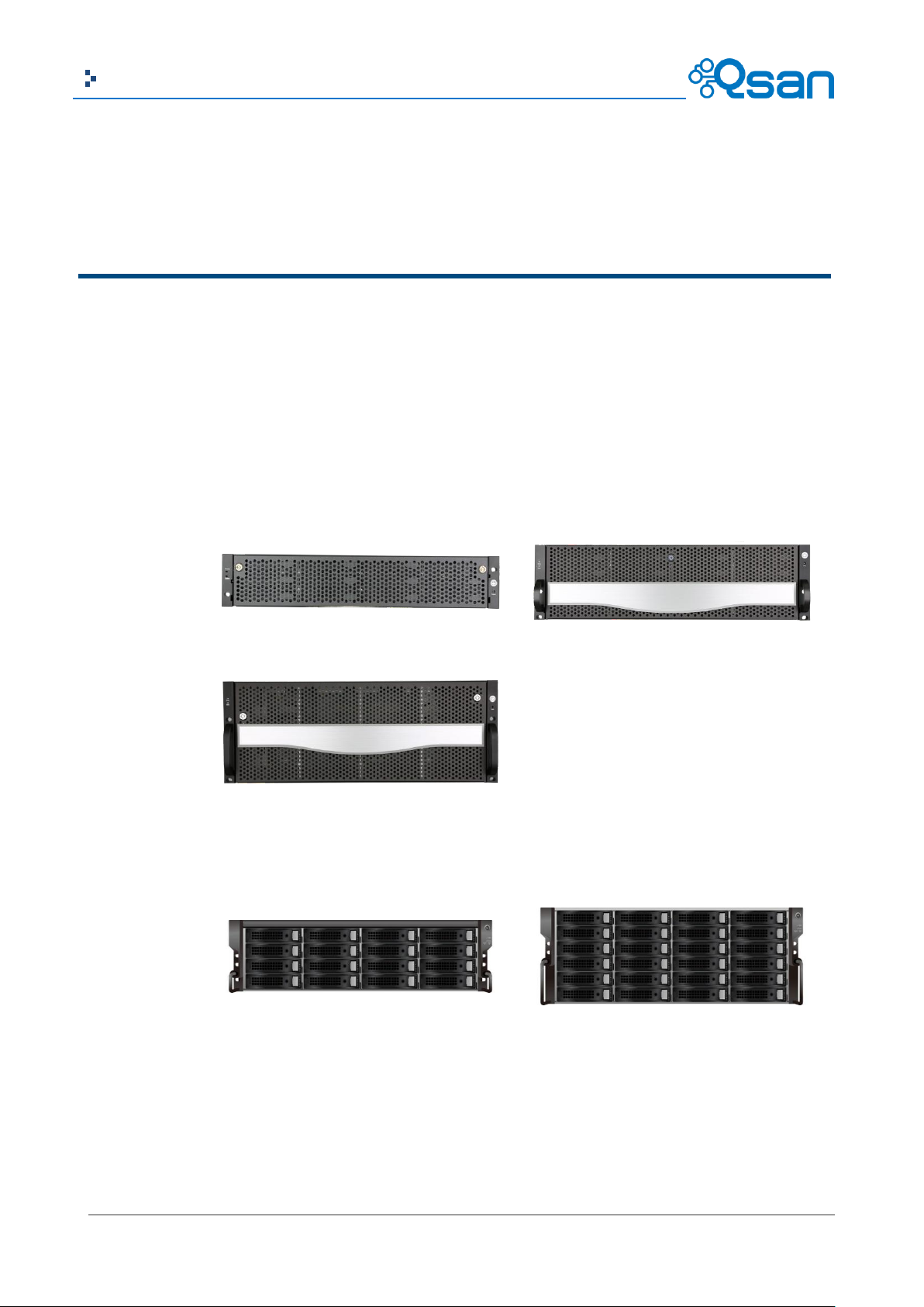
AegisSAN Q500
(2U12bays)
AegisSAN Q500
(3U16bays)
AegisSAN Q500
(4U24bays)
AegisSAN V100 and J100
(3U16bays)
AegisSAN V100 and J100
(4U24bays)
Product Overview
This user manual describes how to set up and use the Qsan storage systems. There are several
types of chassis available now.
AegisSAN Q500 Series:
AegisSAN V100 Series and JBOD J100 Series:
Page 13
13
Copyright@2004~2014 Qsan Technology, Inc. All Rights Reserved.
Qsan Document – User Manual
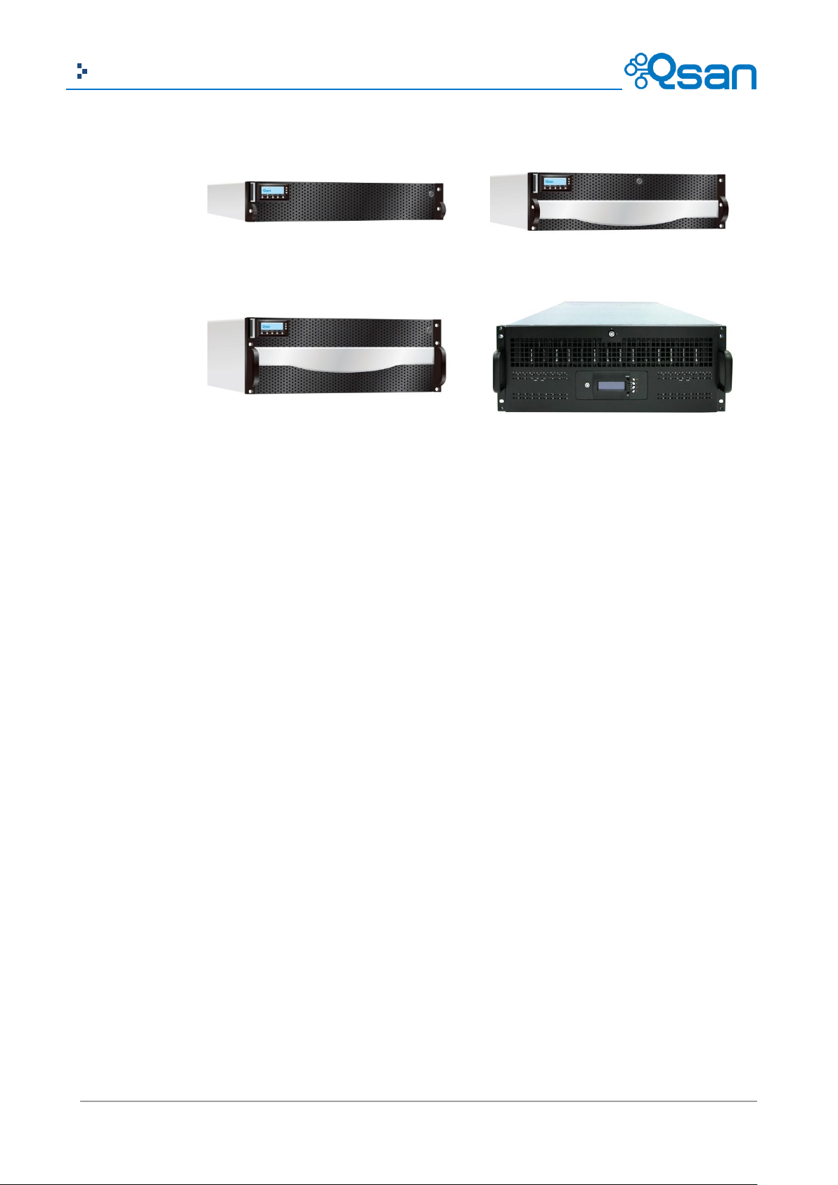
AegisSAN LX 212 and J300Q
(2U12bays)
AegisSAN LX 316 and J300Q
(3U16bays)
AegisSAN LX 424 and J300Q
(4U24bays)
AegisSAN LX 460 and J300Q
(4U60bays)
AegisSAN LX Series and JBOD J300Q Series:
The storage array, available in different configurations of Fibre Channel, GbE iSCSI, 10GbE iSCSI
and SAS interfaces, provides a flexible, intelligent, storage area network (SAN) solution for
virtualized server environments and the glowing demand for data storage. Qsan storage systems
can provide non-stop service with a high degree of fault tolerance by using Qsan RAID technology
and advanced array management features.
Model Comparison
Qsan storage system AegisSAN Q500-XXX-Xxxx, AegisSAN V100-XXX-Xxxx and AegisSAN LX
XXXXQ-Xxxx stands for the following models.
AegisSAN Q500-XXX stands for front-end interfaces:
Q500-P10: 6 x GbE iSCSI ports per controller.
Q500-P20: 2 x 10GbE iSCSI ports (SFP+) + 2 x GbE iSCSI ports per controller.
Q500-P21: 2 x 10GbE iSCSI ports (10GBASE-T) + 2 x GbE iSCSI ports per controller.
Q500-F20: 2 x 8Gb Fibre Channel ports (SFP+) + 2 x GbE iSCSI ports per controller.
Q500-F21: 4 x 8Gb Fibre Channel ports (SFP+) + 2 x GbE iSCSI ports per controller.
Q500-F30: 2 x 16Gb Fibre Channel ports (SFP+) + 2 x GbE iSCSI ports per controller.
AegisSAN V100-XXX stands for front-end interfaces:
V100-P10: 6 x GbE iSCSI ports per controller.
V100-P20: 2 x 10GbE iSCSI ports (SFP+) + 6 x GbE iSCSI ports per controller.
V100-F30: 2 x 16Gb Fibre Channel ports (SFP+) + 6 x GbE iSCSI ports per controller.
Page 14

14
Copyright@2004~2014 Qsan Technology, Inc. All Rights Reserved.
Qsan Document – User Manual
Host Interface
2U12
3U16
4U24
6 x GbE iSCSI
Q500-P10-D212
Q500-P10-S212
Q500- P10-D316
Q500- P10-S316
Q500- P10-D424
Q500- P10-S424
2 x 10GbE iSCSI (SFP+)
+ 2 x GbE iSCSI
Q500-P20-D212
Q500-P20-S212
Q500- P20-D316
Q500- P20-S316
Q500- P20-D424
Q500- P20-S424
2 x 10GbE iSCSI
(10GBASE-T)
+ 2 x GbE iSCSI
Q500-P21-D212
Q500-P21-S212
Q500- P21-D316
Q500- P21-S316
Q500- P21-D424
Q500- P21-S424
2 x 8Gb FC (SFP+)
+ 2 x GbE iSCSI
Q500-F20-D212
Q500-F20-S212
Q500-F20-D316
Q500-F20-S316
Q500-F20-D424
Q500-F20-S424
4 x 8Gb FC (SFP+)
+ 2 x GbE iSCSI
Q500-F21-D212
Q500-F21-S212
Q500-F21-D316
Q500-F21-S316
Q500-F21-D424
Q500-F21-S424
2 x 16Gb FC (SFP+)
+ 2 x GbE iSCSI
Q500-F30-D212
Q500-F30-S212
Q500-F30-D316
Q500-F30-S316
Q500-F30-D424
Q500-F30-S424
AegisSAN LX XXXXQ stands for front-end interfaces:
P400Q: 6 x GbE iSCSI ports per controller.
P600Q: 2 x 10GbE iSCSI ports (SFP+) + 2 x GbE iSCSI ports per controller.
F600Q: 4 x 8Gb Fibre Channel ports (SFP+) + 2 x GbE iSCSI ports per controller.
F630Q: 2 x 16Gb Fibre Channel ports (SFP+) + 2 x GbE iSCSI ports per controller.
JBOD JXXX(Q) stands for front-end interfaces:
J100: 6G SAS JBOD (IN) + 6G SAS JBOD (OUT) ports per controller.
J300Q: 6G SAS JBOD (IN) + 6G SAS JBOD (OUT) ports per controller.
X stands for { D | S | C}:
D: Dual controller.
S: Single controller, but can be upgradable to dual.
C: Single controller only.
xxx stands for chassis height and HDD bays. It can be { 212 | 224 | 316 | 424 | 460 }:
212: 2U 12 bays with 3.5” HDD trays.
224: 2U 24 bays with 2.5” HDD trays.
316: 3U 16 bays with 3.5” HDD trays.
424: 4U 24 bays with 3.5” HDD trays.
460: 4U 60 bays with 3.5” HDD trays.
AegisSAN Q500 Series:
Page 15

15
Copyright@2004~2014 Qsan Technology, Inc. All Rights Reserved.
Qsan Document – User Manual
Host Interface
3U16
4U24
6 x GbE iSCSI
V100- P10-C316
V100- P10-C424
2 x 10GbE iSCSI (SFP+)
+ 6 x GbE iSCSI
V100- P20-C316
V100- P20-C424
2 x 16Gb FC (SFP+)
+ 6 x GbE iSCSI
V100-F30-C316
V100-F30-C424
Host Interface
2U12
3U16
4U24
4U60
6 x GbE iSCSI
P400Q-D212
P400Q-S212
P400Q-D316
P400Q-S316
P400Q-D424
P400Q-S424
P400Q-D460
P400Q-S460
2 x 10GbE iSCSI (SFP+)
+ 2 x GbE iSCSI
P600Q-D212
P600Q-S212
P600Q-D316
P600Q-S316
P600Q-D424
P600Q-S424
P600Q-D460
P600Q-S460
4 x 8Gb FC (SFP+)
+ 2 x GbE iSCSI
F600Q-D212
F600Q-S212
F600Q-D316
F600Q-S316
F600Q-D424
F600Q-S424
F600Q-D460
F600Q-S460
2 x 16Gb FC (SFP+)
+ 2 x GbE iSCSI
F630Q-D212
F630Q-S212
F630Q-D316
F630Q-S316
F630Q-D424
F630Q-S424
N/A
Host Interface
2U12
2U24
3U16
4U24
4U60
6G SAS JBOD
N/A
N/A
J100-C316
J100-C424
N/A
6G SAS JBOD
J300Q-D212
J300Q-C212
J300Q-D224
J300Q-C224
J300Q-D316
J300Q-C316
J300Q-D424
J300Q-C424
J300Q-D460
J300Q-C460
AegisSAN V100 Series:
AegisSAN LX Series:
JBOD Series:
The dual controller specific functions such as dual-active, cache mirroring, flexible RAID group
ownership management, management port seamless take-over, no system down time, and etc are
not available in Q500-XXX-Sxxx and XXXXQ-Sxxx series.
Package Contents
The package contains the following items:
Qsan storage system (x1).
HDD trays (x12) (2U12).
HDD trays (x16) (3U16).
HDD trays (x24) (2U24 / 4U24).
HDD trays (x60) (4U60).
Power cords (x2) (2U12 / 2U24 / 3U16).
Power cords (x3) (4U24 / 4U60).
Page 16
16
Copyright@2004~2014 Qsan Technology, Inc. All Rights Reserved.
Qsan Document – User Manual
AegisSAN Q500
(2U12bays)
AegisSAN Q500
(3U16bays)
AegisSAN Q500
(4U24bays)
AegisSAN V100 and J100
(3U16bays)
AegisSAN V100 and J100
(4U24bays)
AegisSAN LX 212 and J300Q
(2U12bays)
AegisSAN LX 316 and J300Q
(3U16bays)
Hardware
RS-232 cables (x2), one is for console (black color, phone jack to DB9 female), and the other
is for UPS (gray color, phone jack to DB9 male) (AegisSAN LX).
LCM with USB (x1) (AegisSAN Q500).
Rail kit (x1 set).
Keys, screws for drives and rail kit (x1 packet).
Disk tool (x1) (4U60).
This section provides basic information about the hardware components.
AegisSAN Q500 Series:
AegisSAN V100 Series and JBOD J100 Series:
AegisSAN LX Series and JBOD J300Q Series:
Page 17
17
Copyright@2004~2014 Qsan Technology, Inc. All Rights Reserved.
Qsan Document – User Manual
AegisSAN LX 424 and J300Q
(4U24bays)
AegisSAN LX 460 and J300Q
(4U60bays)
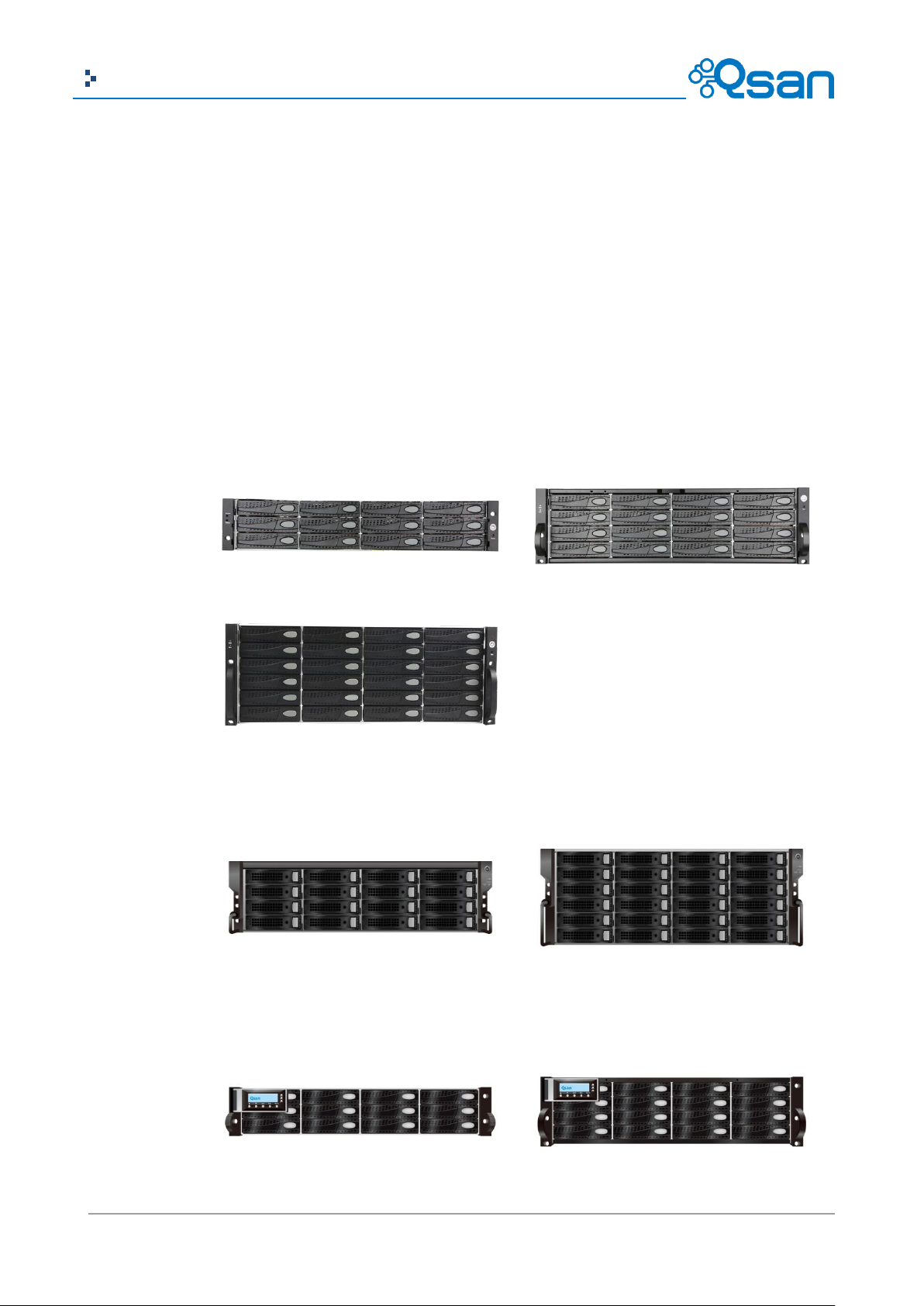
Number
Description
1
USB port:
This is designed specifically for USB LCM usage. It DOES NOT offer external
USB storage function.
2
Access LED:
This indicates the host interface (frontend) connectivity, not the hard drive
activity. Please be aware.
Blink: There is host interface activity (data I/O or management).
OFF: There is no host interface activity.
3
Status LED:
Red: System failure.
Off: System OK.
1
2
3
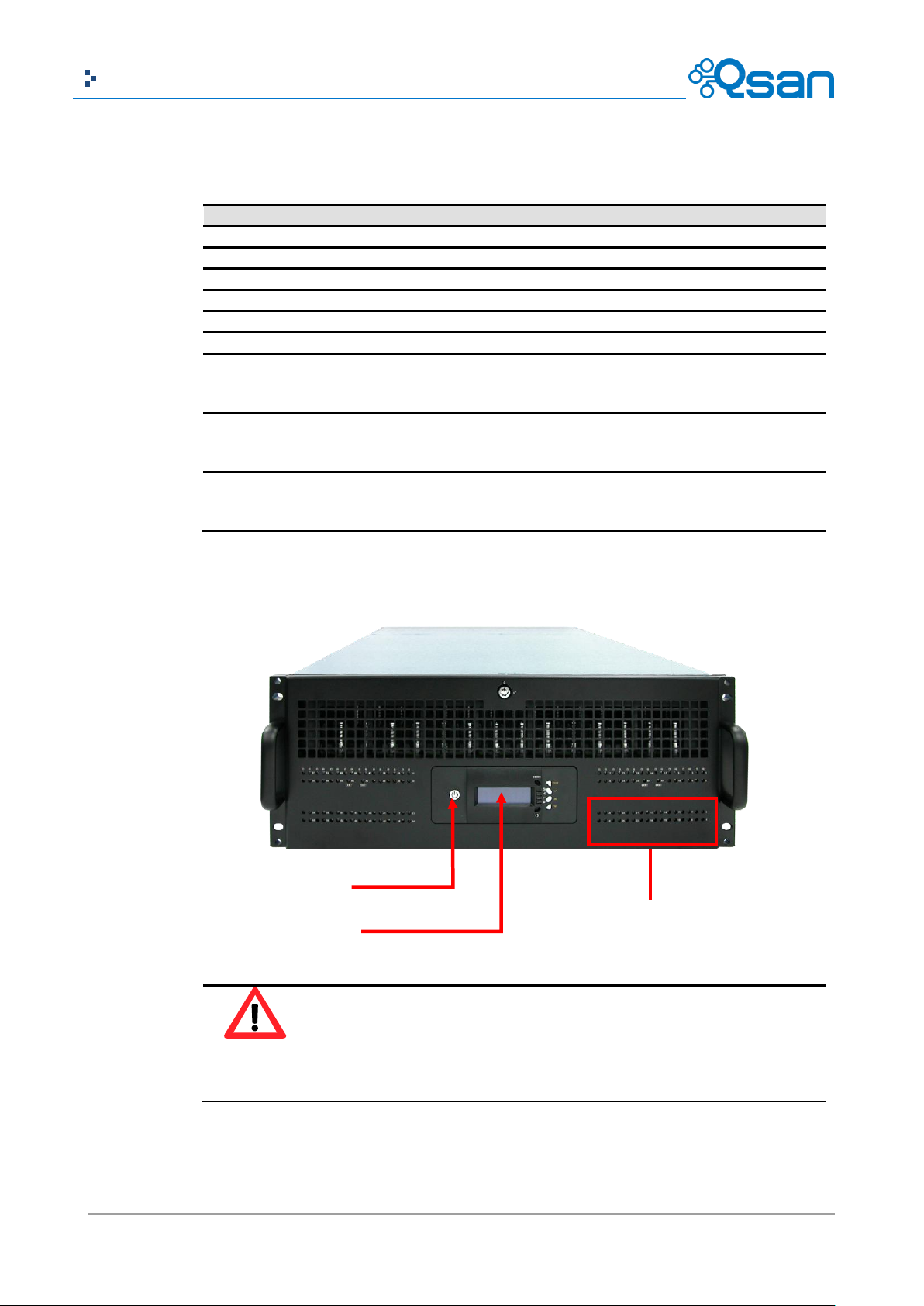
Front View
AegisSAN Q500 Series (2U12 / 3U16 / 4U24):
There is a power switch button at the right front handle; a LCM with the USB interface at the left
front handle.
Page 18
18
Copyright@2004~2014 Qsan Technology, Inc. All Rights Reserved.
Qsan Document – User Manual
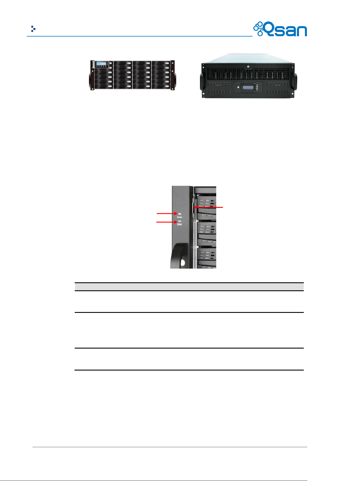
Number
Description
1
Power button and power LED:
Blue: Power ON.
Off: Power OFF.
2
Reset button:
Press within 2 seconds to reset the system to default settings. The default
resets include:
Management IP Address: 192.168.1.234
User Name: admin
Password: 1234
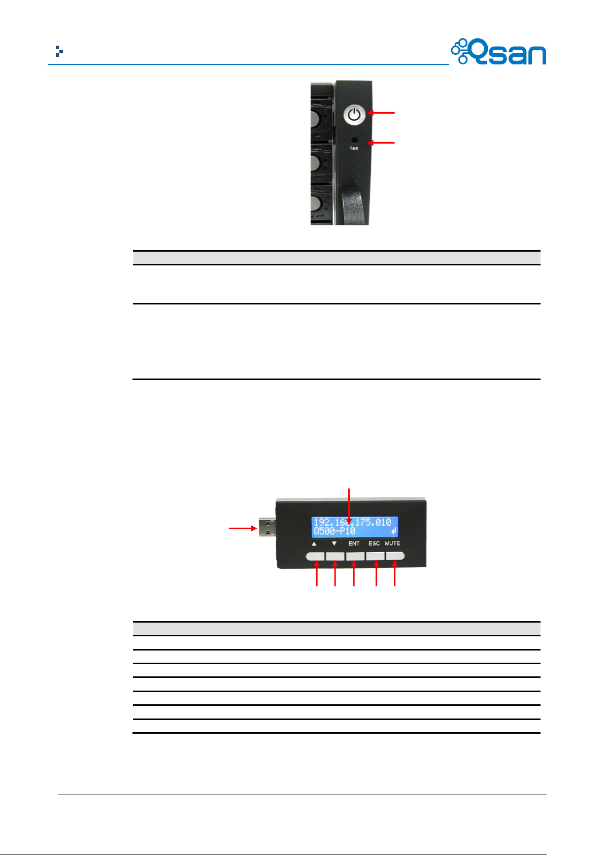
Number
Description
1
LCD display.
2
Up button.
3
Down button.
4
ENT (Enter) button.
5
ESC (Escape) button.
6
MUTE button.
7
USB connector
1
2 1 2 3 4 5 6
7
USB LCM comes as an optional device to Q500 series. The standard SKU doesn’t include USB LCM.
Both the USB port on the front left handle and the USB port on the controller itself support LCM
function. However, the USB port doesn’t support external USB storage function.
AegisSAN V100 Series and JBOD J100 Series (3U16 / 4U24):
Page 19
19
Copyright@2004~2014 Qsan Technology, Inc. All Rights Reserved.
Qsan Document – User Manual
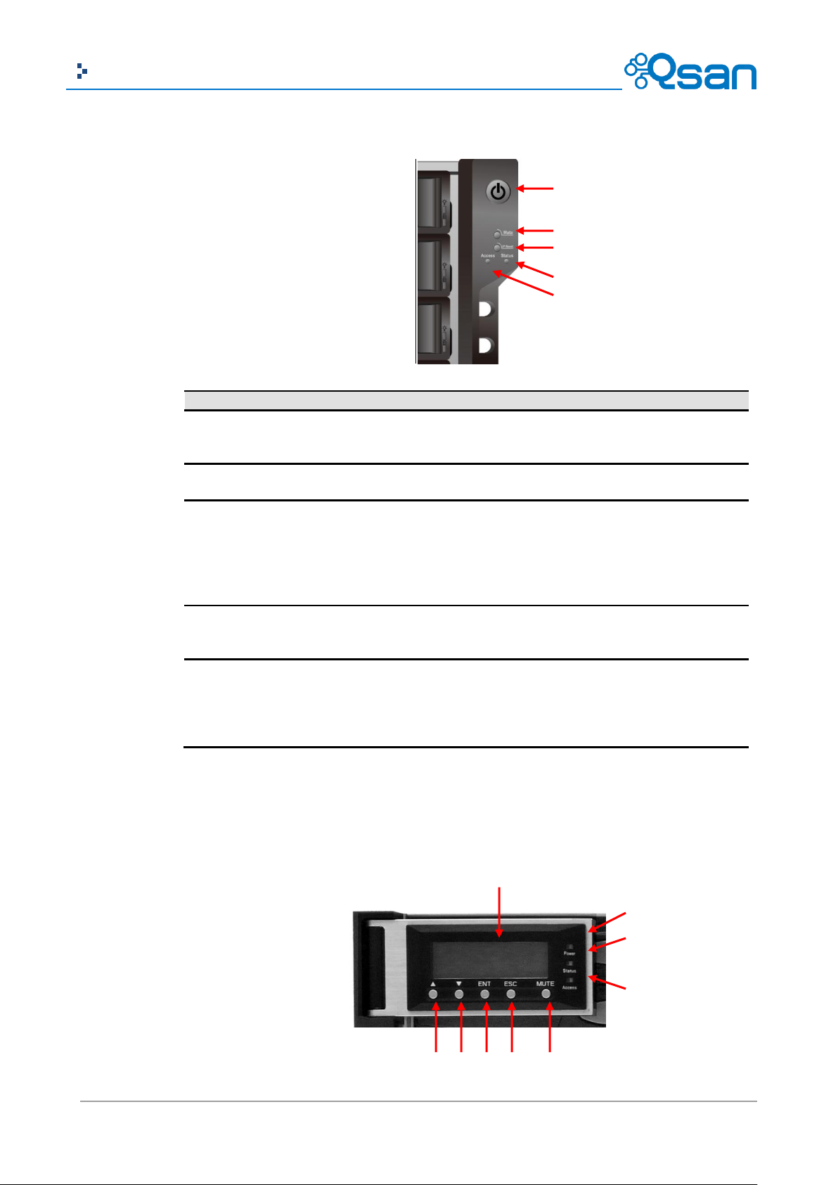
Number
Description
1
Power button and power LED:
Blue: Power ON.
Off: Power OFF.
2
MUTE button:
Press to mute the alarm.
3
IP Reset button: (J100 has no function at this button)
Press within 2 seconds to reset the system to default settings. The default
resets include:
Management IP Address: 192.168.1.234
User Name: admin
Password: 1234
4
Status LED:
Red: System failure.
Off: System OK.
5
Access LED:
This indicates the host interface (frontend) connectivity, not the hard drive
activity. Please be aware.
Blink: There is host interface activity (data I/O or management).
OFF: There is no host interface activity.
6
8 9 2 3 4 5 1 7 1
2 3 5
4
There is a power switch button at the right front handle.
AegisSAN LX Series and JBOD J300Q Series (2U12 / 3U16 / 4U24):
There are five buttons to control LCM (LCD Control Module), including:
(up), (down), ENT (Enter), ESC (Escape) and MUTE.
Page 20
20
Copyright@2004~2014 Qsan Technology, Inc. All Rights Reserved.
Qsan Document – User Manual
Number
Description
1
LCD display.
2
Up button.
3
Down button.
4
ENT (Enter) button.
5
ESC (Escape) button.
6
MUTE button.
7
Power LED:
Green: Power ON.
Off: Power OFF.
8
Status LED:
Red: System failure.
Off: System OK.
9
Access LED:
Blue: Host is accessing storage system.
Off: No host access attempts.
CAUTION:
When powering off the subsystem, press the Main Switch for 4 seconds and
allow at least 3 minutes (during which each disk slot starting from slot #1 until
slot #60 will be powered down) for the subsystem to shutdown properly. Then
turn off the switches of the 2 Power Supply Fan Modules.
Main Switch
HDD Status Indicator
Display Panel
This table shows the items located on the LCD Control Module.
AegisSAN LX Series and J300Q Series (4U60):
Page 21
21
Copyright@2004~2014 Qsan Technology, Inc. All Rights Reserved.
Qsan Document – User Manual
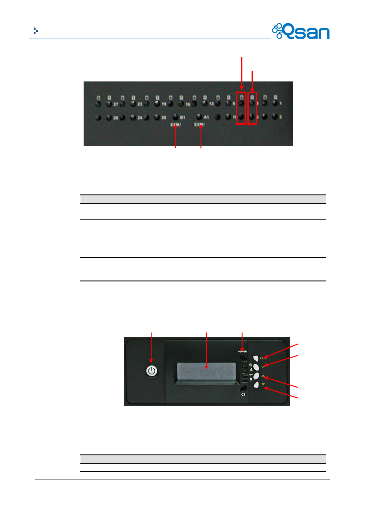
Number
Description
1
Activity LED:
Blinking blue: Indicates the drive is busy or being accessed.
2
Power On / Fail LED:
Green: Indicates the drive in this slot is good.
Red: Indicates the drive in this slot is faulty.
Blinking Red: Indicates the drive in this slot is rebuilding.
Off: Indicates there is no drive in this slot.
3
Expander module Fault LED:
Red: Indicates the Expander module is faulty.
Off: Indicates the Expander module is normal.
Number
Description
1
LCD display.
1. Activity LED
2. Power On/Fail LED
3 4 1 2 5 67 ~ 12
3
3
This table shows the items located on the LCD Control Module.
There are four buttons to control LCM (LCD Control Module), including:
(up), (down), V (Select), and EXIT (Escape).
This table shows the items located on the LCD Control Module.
Page 22
22
Copyright@2004~2014 Qsan Technology, Inc. All Rights Reserved.
Qsan Document – User Manual
2
EXIT (Escape) button.
3
V (Select) button.
4
Up button.
5
Down button.
6
Power button.
7
Power LED:
Green: Power ON.
Off: Power OFF.
8
Power Fail LED:
Red: If one of the redundant power supply unit fails, this LED will
turn to RED and alarm will sound.
Off: System OK.
9
Fan Fail LED:
Red: If a fan fails, this LED will turn red and an alarm will sound.
Off: Fan OK.
10
Over Temperature LED:
Red: If temperature irregularities in the system occur, this LED will
turn RED and alarm will sound.
Off: Temperature OK.
11
Voltage Warning LED:
Red: If the output DC voltage is above or below the allowed range,
an alarm will sound warning of a voltage abnormality and this LED
will turn red.
Off: Voltage OK.
12
Activity LED:
Blinking blue: When the disk array is busy or being accessed.
Off: Idle.
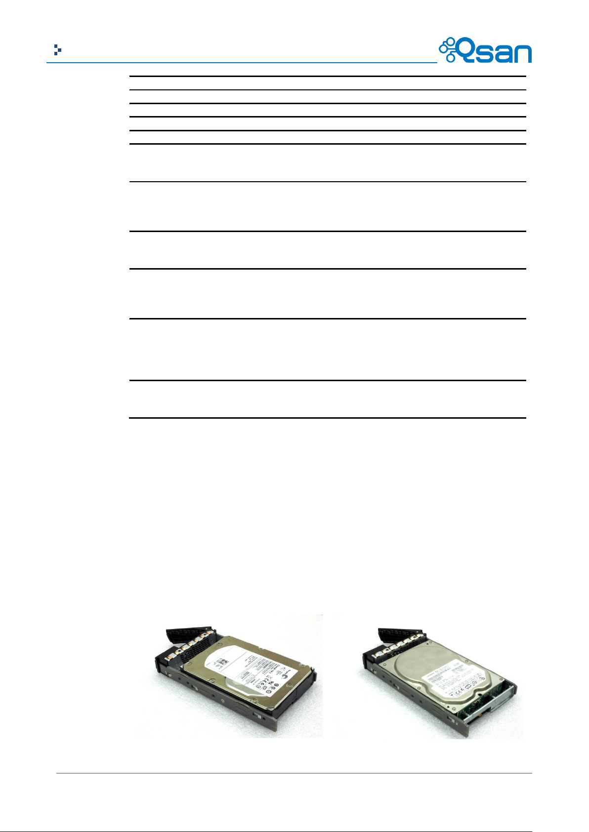
SAS Drive
SATA Drive
Disk Drive Assembly
AegisSAN Q500 Series, AegisSAN LX Series and JBOD J300Q Series (2U12 / 3U16 / 4U24):
Remove a drive tray. Then install a HDD.
To install SAS drives: align the edge of the drive to the back end of tray; the backplane can
directly connect to the drives.
To install SATA drives with 3G/6G MUX boards: align the board edge to the back end of tray;
the backplane can connect the drives through the boards.
Page 23
23
Copyright@2004~2014 Qsan Technology, Inc. All Rights Reserved.
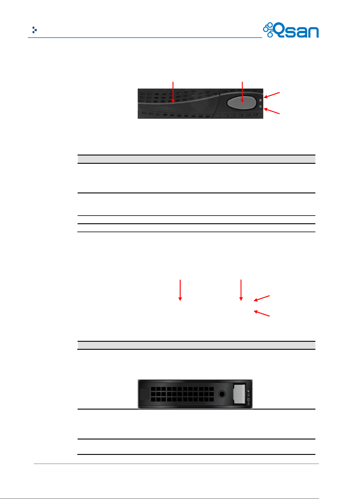
Qsan Document – User Manual
Number
Description
1
Power LED:
Green: Drive is inserted and good.
Red: Drive fails.
Off: No drive in the tray.
2
Access LED:
Blue blinking: The drive is being accessed.
Off: The drive is not being accessed or no drive in the tray.
3
Tray removal handle.
4
Latch to release the tray.
Number
Description
1
Power LED:
Green: Drive is inserted and good.
Red: Drive fails.
Off: No drive in the tray.
2
Access LED:
Blue blinking: The drive is being accessed.
1
2 3 4
1 2 3
4
The front of each disk tray has four components:
This table provides details about the front components of a disk tray.
AegisSAN V100 Series and JBOD J100 Series (3U16 / 4U24):
The front of each disk tray has four components:
This table provides details about the front components of a disk tray.
Page 24
24
Copyright@2004~2014 Qsan Technology, Inc. All Rights Reserved.
Qsan Document – User Manual
Off: The drive is not being accessed or no drive in the tray.
3
Tray removal handle.
4
Latch to release the tray and tray lock.
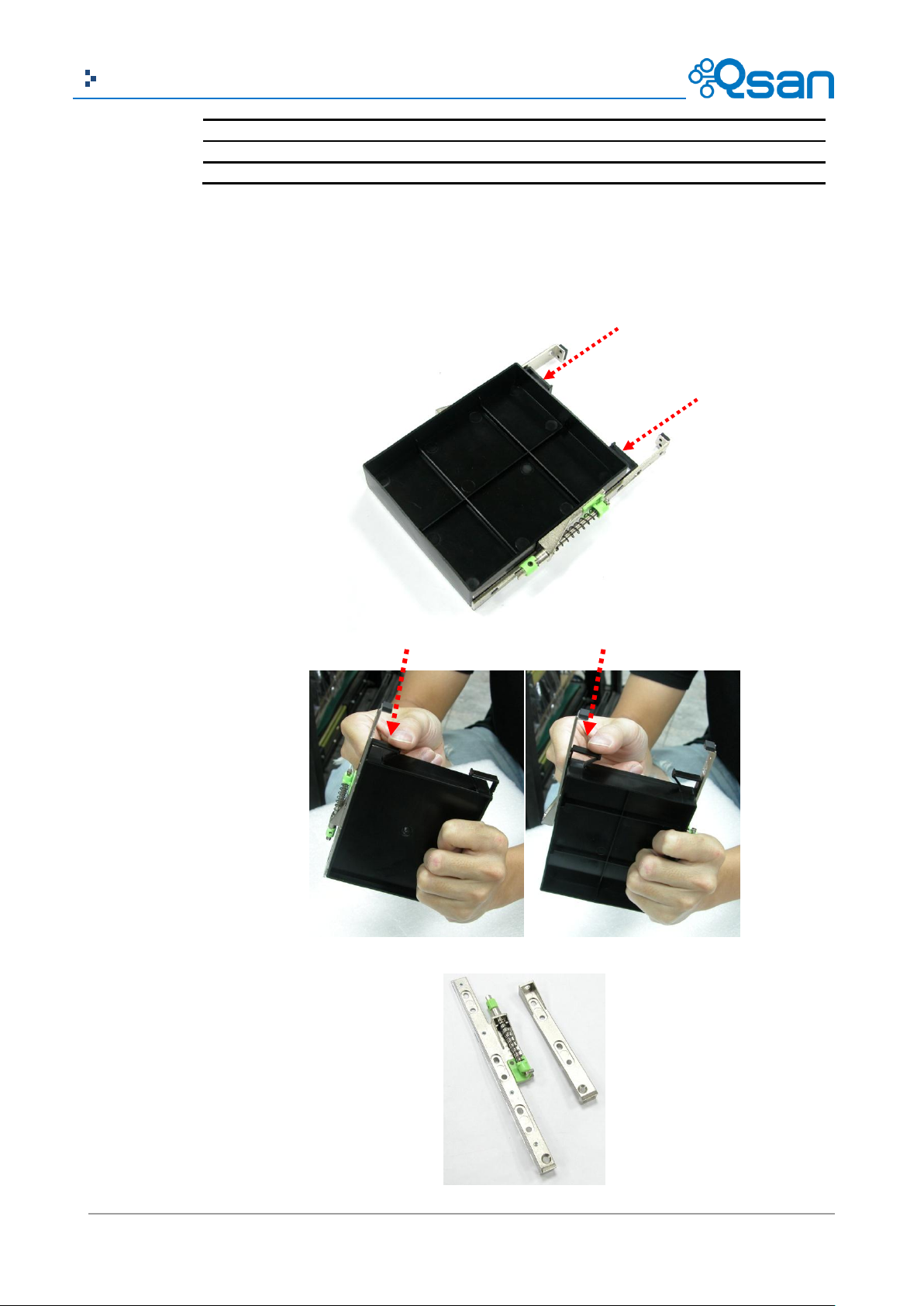
AegisSAN LX Series and JBOD J300Q Series (4U60):
1. Prepare the HDD side brackets. Remove them from the dummy disk by pushing the upper
sides of the dummy disk as shown below:
Page 25
25
Copyright@2004~2014 Qsan Technology, Inc. All Rights Reserved.
Qsan Document – User Manual
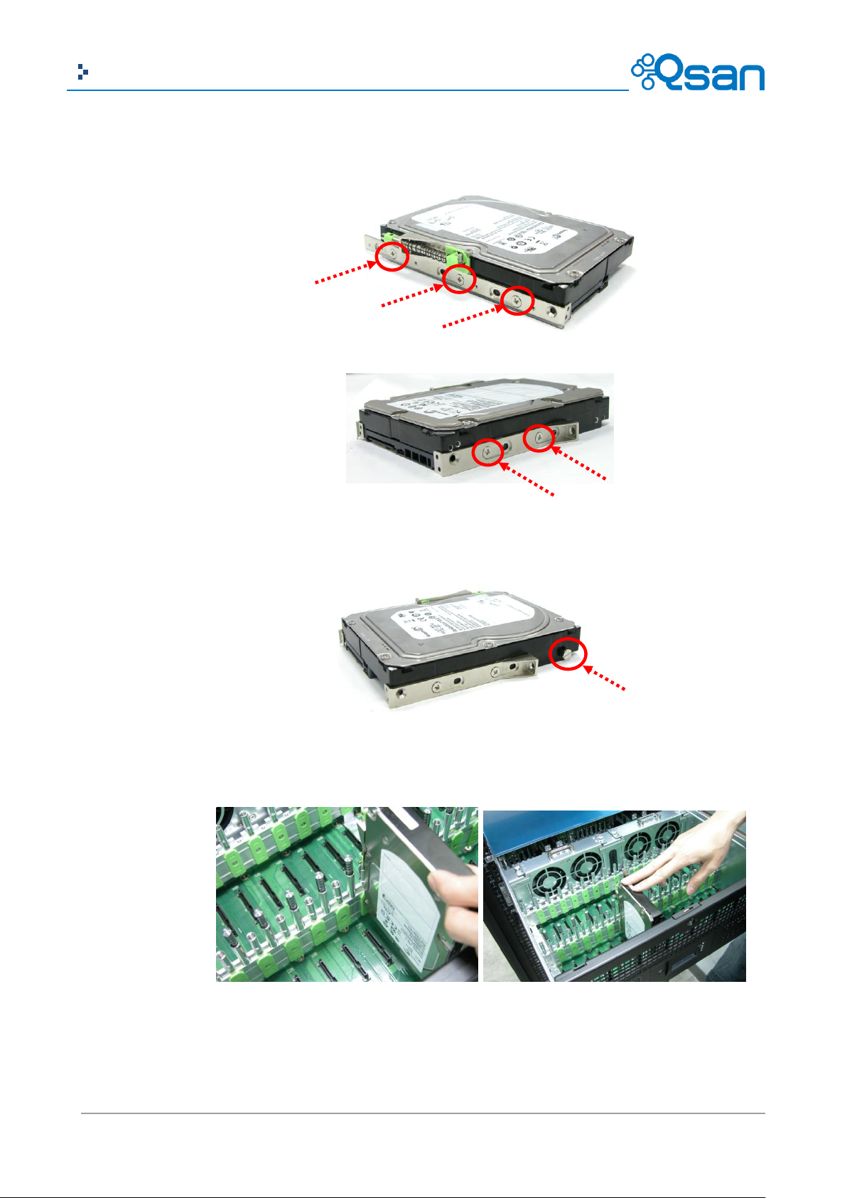
2. Place the brackets on both sides of the disk drive and secure them with screws.
3. Place the slotted flat head screw.
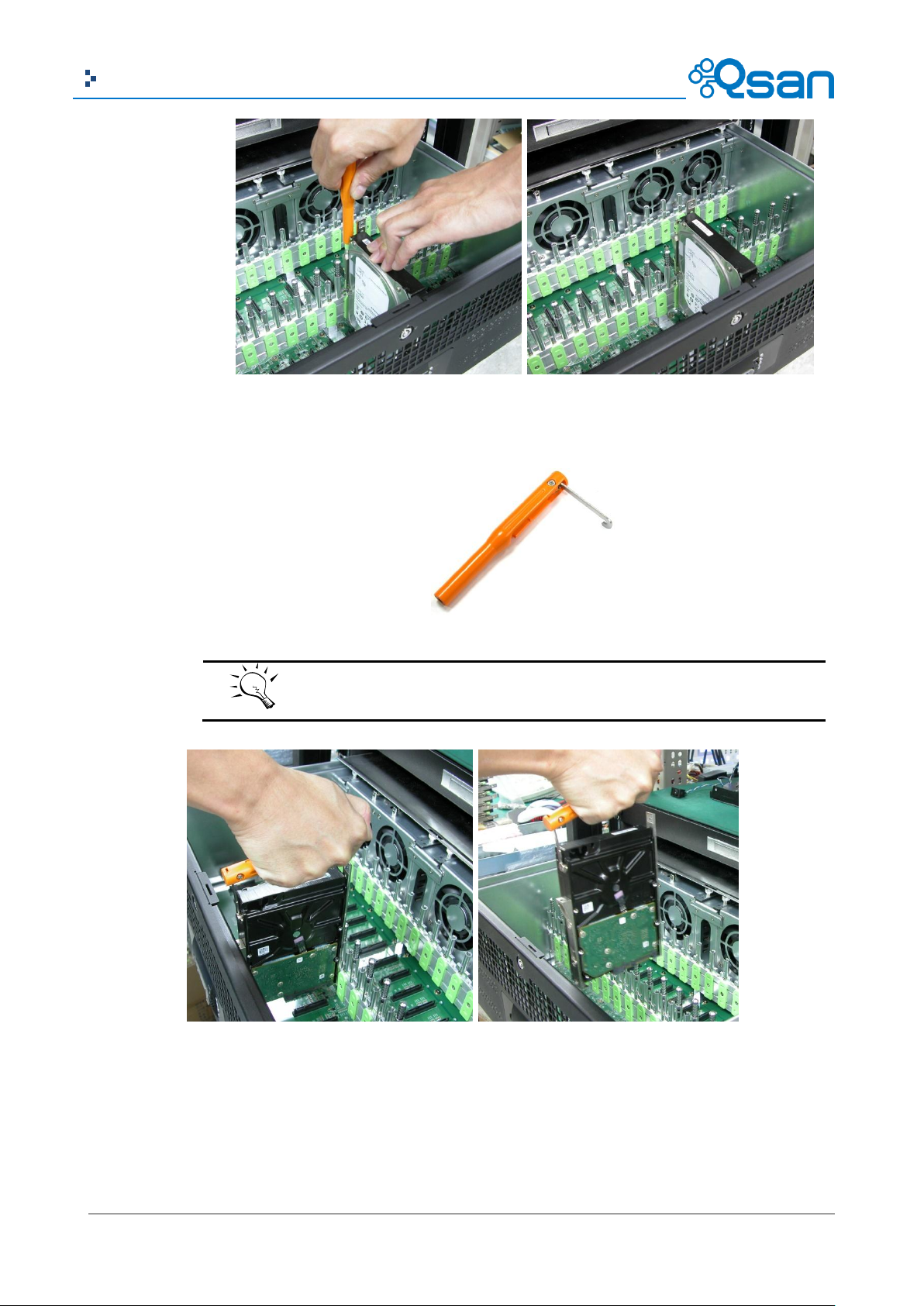
4. Place the drive carefully in the disk slot.
5. Fix the disk drive using the disk tool that is included in the package.
Page 26
26
Copyright@2004~2014 Qsan Technology, Inc. All Rights Reserved.
Qsan Document – User Manual
TIP:
You can use also the disk tool to remove the disk drive in the disk slot.
6. Repeat the same steps for the rest of the disks
3TB / 6G MUX Board Limitation
AegisSAN Q500 Series and AegisSAN LX Series:
Page 27

27
Copyright@2004~2014 Qsan Technology, Inc. All Rights Reserved.
Qsan Document – User Manual
System
JBOD
Single upgradable
Dual
Single
Dual
Q500-XXX-Sxxx
F600Q-Sxxx
P400Q-Sxxx
P600Q-Sxxx
Q500-XXX-Dxxx
F600Q-Dxxx
P400Q-Dxxx
P600Q-Dxxx
J300Q-Cxxx
J300Q-Dxxx
<= 2TB SATA
No
6G MUX board
No
6G MUX board
> 2TB SATA
No
6G MUX board
No
6G MUX board
<= 2TB SAS
No
No
No
No
> 2TB SAS
No
No
No
No HDD Type
6G MUX Board
3G MUX Board
SATA
3TB
2794 GB
2794 GB
SATA 6Gb/s
SATA 6Gb/s
SATA 3Gb/s
SATA 3Gb/s
SATA 6Gb/s
SATA 3Gb/s
SATA 1.5Gb/s
SATA 6Gb/s
SATA 1.5Gb/s Without MUX Board
SAS
3TB
2794 GB
SAS 6Gb/s
SAS 6Gb/s
SAS 3Gb/s
SAS 3Gb/s
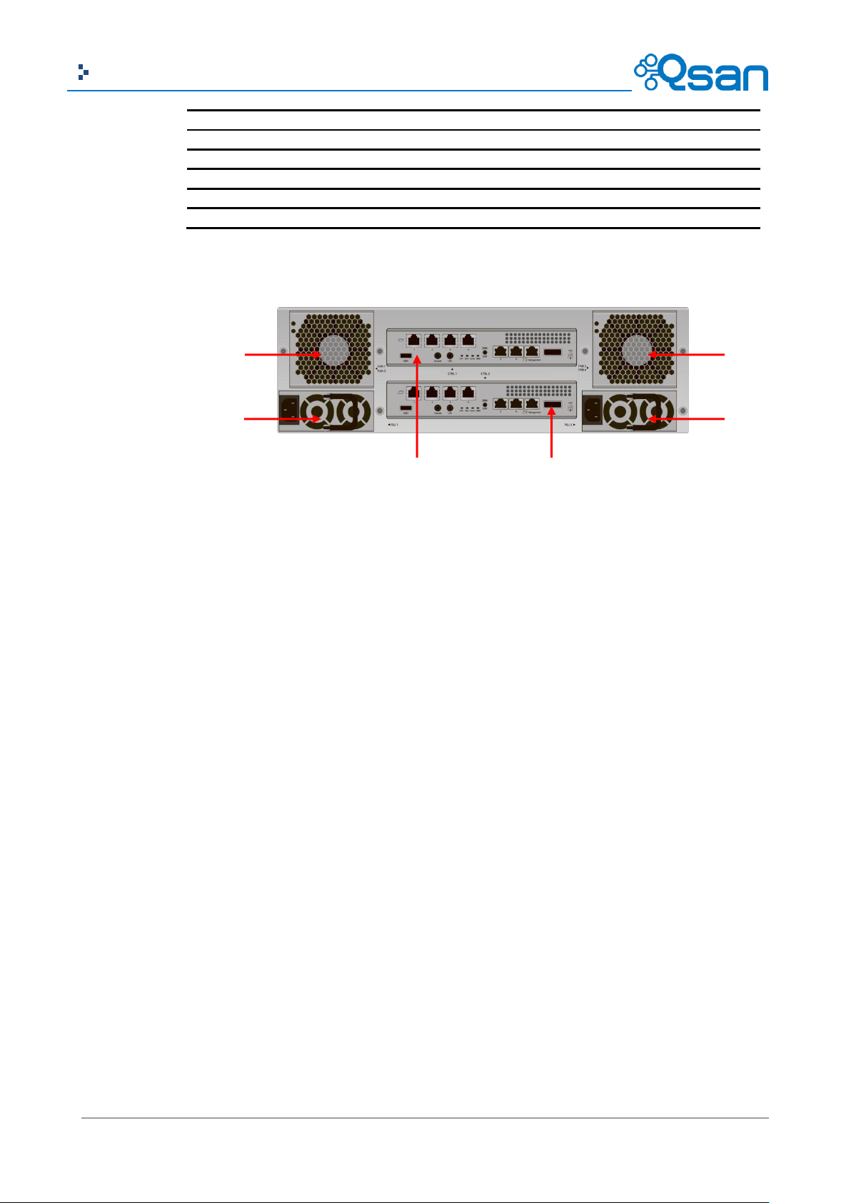
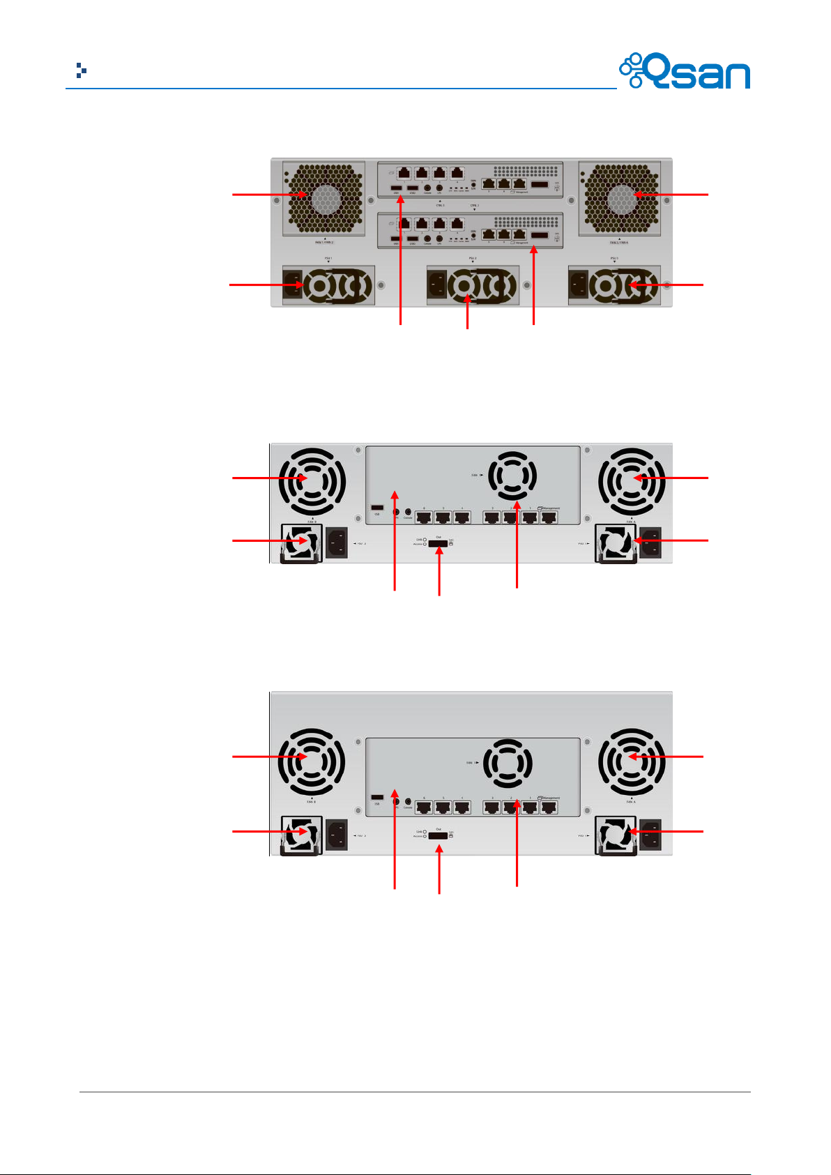
Number
Description
1
Controller 1 (CTRL 1).
2
Controller 2 (CTRL 2, only for dual-controller).
3
Power Switch
|: ON.
O: OFF.
4
Fan Module (FAN1 / FAN2).
5
Fan Module (FAN3 / FAN4).
67 5 1 4
2
Rear View
There are several various chassis available. The following examples show the AegisSAN Q500-P10,
AegisSAN V100-P10, and AegisSAN LX P400Q series.
AegisSAN Q500 2U12 chassis:
This table describes the rear modules.
Page 28
28
Copyright@2004~2014 Qsan Technology, Inc. All Rights Reserved.
Qsan Document – User Manual
6
Power Supply Unit (PSU1).
7
Power Supply Unit (PSU2).
8
Power Supply Unit (PSU3).
9
Fan Module (FAN A).
10
Fan Module (FAN B).
11
SAS JBOD expansion port.
45 7
1 6 2
AegisSAN Q500 3U16 chassis:
Page 29
29
Copyright@2004~2014 Qsan Technology, Inc. All Rights Reserved.
Qsan Document – User Manual
4 5 7 1 6 2 7
10 9 6 1 7
11
4
10
9
6 1 7
11
4
AegisSAN Q500 4U24 chassis:
AegisSAN V100 3U16 chassis:
AegisSAN V100 4U24 chassis:
Page 30

30
Copyright@2004~2014 Qsan Technology, Inc. All Rights Reserved.
Qsan Document – User Manual
4
5
7
1 3 6
2 2 6 7 5 1 4
3
4
5
8
1 3 7 6 2
AegisSAN LX 2U12 chassis:
AegisSAN LX 3U16 chassis:
AegisSAN LX 4U24 chassis:
Page 31

31
Copyright@2004~2014 Qsan Technology, Inc. All Rights Reserved.
Qsan Document – User Manual
Number
Description
1
Controller 1 (CTRL 1).
2
Controller 2 (CTRL 2, only for dual-controller).
3
Power Switch
|: ON.
O: OFF.
4
Power Supply Unit (PSU1) and Fan Module (FAN1).
5
Power Supply Unit (PSU2) and Fan Module (FAN2).
6
Power Supply Unit (PSU3) and Fan Module (FAN3).
7
Fan Module (FAN4 / FAN5).
8
Fan Module (FAN6 / FAN7).
9
Expander Module (A1 / single controller).
Expander Module (B1 / only for dual-controller).
10
Expander Module (A2 / single controller).
Expander Module (B2 / only for dual-controller).
11
Fan Module (FAN8).
12
Fan Module (FAN9).
13
Fan Module (FAN10).
14
Fan Module (FAN11).
4 3 2 7 1 5 6
8
AegisSAN LX 4U60 chassis:
This table describes the rear modules.
Page 32
32
Copyright@2004~2014 Qsan Technology, Inc. All Rights Reserved.
Qsan Document – User Manual
13.Fan10
14.Fan11
11.Fan8
12.Fan9
10.A2/B2
9.A1/B1
There are many various controllers available. With the exception of the host SAN ports, the
connections are the same on all modules.
Page 33

33
Copyright@2004~2014 Qsan Technology, Inc. All Rights Reserved.
Qsan Document – User Manual
Number
Description
1
SAN ports (depending on model):
AegisSAN Q500:
Q500-P10: 6 x GbE iSCSI ports.
Q500-P20: 2 x 10GbE iSCSI ports (SFP+) + 2 x GbE iSCSI ports.
Q500-P21: 2 x 10GbE iSCSI ports (10GBASE-T) + 2 x GbE iSCSI ports.
Q500-F20: 2 x 8Gb Fibre Channel ports + 2 x GbE iSCSI ports.
Q500-F21: 4 x 8Gb Fibre Channel ports + 2 x GbE iSCSI ports.
Q500-F30: 2 x 16Gb Fibre Channel ports + 2 x GbE iSCSI ports.
AegisSAN V100:
V100-P10: 6 x GbE iSCSI ports.
V100-P20: 2 x 10GbE iSCSI ports + 6 x GbE iSCSI ports.
V100-F30: 2 x 16Gb Fibre Channel ports + 6 x GbE iSCSI ports.
AegisSAN LX:
F600Q: 4 x 8Gb Fibre Channel ports + 2 x GbE iSCSI ports.
F630Q: 2 x 16Gb Fibre Channel ports + 2 x GbE iSCSI ports.
P400Q: 6 x GbE iSCSI ports.
P600Q: 2 x 10GbE iSCSI ports + 2 x GbE iSCSI ports.
2
LED (from left to right for 4U24 / 3U16 chassis, from right to left for 2U12
chassis):
Controller health LED:
Green: Controller status normal.
Red: System booting or controller failure.
Master slave LED (only for dual controllers):
Green: This is the Master controller.
Off: This is the Slave controller.
Dirty cache LED:
Orange: Data on the cache waiting for flush to disks.
Off: No data on the cache.
BBM LED (when status button pressed):
Green: BBM installed and powered.
Off: No BBM installed.
3
BBM status button (used to check the battery when the power is off):
If the BBM LED shows Green, then the BBM still has power to keep
5 6 7 4 2
3 1 9
AegisSAN Q500-P10 (6 x GbE iSCSI) controller:
This table describes the rear components.
Page 34

34
Copyright@2004~2014 Qsan Technology, Inc. All Rights Reserved.
Qsan Document – User Manual
data on the cache.
If the BBM LED stays Off, then the BBM power has run out and it
cannot provide power for the cache anymore. It needs to be
recharged or replaced.
4
Management port.
5
Console port.
6
RS 232 port for UPS.
7
SAS JBOD expansion port.
8
BBM slot.
9
USB
No function. Reserved for the future design purpose.
LED
1GbE Link LED (All):
Orange: Asserted when a 1G link is established and maintained.
Green: Asserted when a 100M link is establish and maintained.
1GbE Access LED (All):
Blinking green: Asserted when the link is established and packets are
being transmitted along with any receive activity.
8G FC Link LED (AegisSAN Q500-F20):
Blue: Asserted when an 8G link is established and maintained.
Amber: Asserted when a 4G and below link is established and
maintained.
8G FC Access / fail LED (AegisSAN Q500-F20):
Green: Asserted when the link is establish.
Blinking green: Asserted when the link is established and packets are
being transmitted along with any receive activity.
Red: Asserted when the link can't establish.
8G FC Link LED (AegisSAN Q500-F21 / AegisSAN LX F600Q):
Blue: Asserted when an 8G link is established and maintained.
Yellow: Asserted when a 4G link is established and maintained.
Blinking yellow: Asserted when a 2G link is established and
maintained.
8G FC Access / fail LED (AegisSAN Q500-F21 / AegisSAN LX F600Q):
Green: Asserted when the link is establish.
Blinking green: Asserted when the link is established and packets are
being transmitted along with any receive activity.
Red: Asserted when the link can't establish.
16G FC Link LED (AegisSAN Q500-F30 / AegisSAN V100-F30 / AegisSAN LX
F630Q):
Blue: Asserted when a 16G link is established and maintained.
Amber: Asserted when an 8G link is established and maintained.
White: Asserted when a 4G and below link is established and
maintained.
16G FC Access / fail LED (AegisSAN Q500-F30 / AegisSAN V100-F30 /
AegisSAN LX F630Q):
Green: Asserted when the link is establish.
Blinking green: Asserted when the link is established and packets are
being transmitted along with any receive activity.
Red: Asserted when the link can't establish.
10GbE Link LED (AegisSAN Q500-P20 / AegisSAN V100-P20 / AegisSAN LX
P600Q):
Orange: Asserted when a 1G link is established and maintained.
Page 35

35
Copyright@2004~2014 Qsan Technology, Inc. All Rights Reserved.
Qsan Document – User Manual
Blue: Asserted when a 10G link is establish and maintained.
10GbE Access LED (AegisSAN Q500-P20 / AegisSAN V100-P20 / AegisSAN
LX P600Q):
Yellow: Asserted when the link is established and packets are being
transmitted along with any receive activity.
CAUTION:
Be aware that when Controller Health LED is in RED, please DO NOT unplug the
controller from the system or turn off the power suddenly. This may cause
unrecoverable damage, which will not be covered by warranty.
5 6 7 4 2
3 1 9
AegisSAN Q500-P20 (2 x 10GbE iSCSI (SFP+) + 2 x GbE iSCSI) controller:
AegisSAN Q500-P21 (2 x 10GbE iSCSI (10GBASE-T) + 2 x GbE iSCSI) controller:
Page 36

36
Copyright@2004~2014 Qsan Technology, Inc. All Rights Reserved.
Qsan Document – User Manual
4 1 6 5 7
2
5 6 7 4 3 1 9
5 6 7 4 2 3 1
9 5 6
7 8 4 2 3
1
9
AegisSAN Q500-F20 (2 x 8G FC (SFP+) + 2 x GbE iSCSI) controller:
AegisSAN Q500-F30 (2 x 16G FC (SFP+)+ 2 x GbE iSCSI) controller:
AegisSAN Q500-F21 (4 x 8G FC (SFP+) + 2 x GbE iSCSI) controller:
AegisSAN V100-P10 (6 x GbE iSCSI) controller:
Page 37

37
Copyright@2004~2014 Qsan Technology, Inc. All Rights Reserved.
Qsan Document – User Manual
5
6
7 8 4 2 3 1 9 4 1 6 5
7
4
1
6
5
7
AegisSAN V100-P20 (2 x 10GbE iSCSI (SFP+) + 6 x GbE iSCSI) controller:
AegisSAN V100-F30 (2 x 16G FC (SFP+) + 6 x GbE iSCSI) controller:
AegisSAN LX P400Q (6 x GbE iSCSI) controller:
Page 38

38
Copyright@2004~2014 Qsan Technology, Inc. All Rights Reserved.
Qsan Document – User Manual
5 6 7 8 4 2 3 1 9
5 6 7 4 2 3 9 8 1 5 6 7 8 4 2 3 1 9 5 6 7 8 4 2 3 1 9
AegisSAN LX P600Q (2 x 10GbE iSCSI (SFP+) + 2 x GbE iSCSI) controller:
AegisSAN LX P600Q (2 x 10GbE iSCSI (10GBASE-T) + 2 x GbE iSCSI) controller:
AegisSAN LX F600Q (4 x 8Gb FC (SFP+) + 2 x GbE iSCSI) controller:
AegisSAN LX F630Q (2 x 16Gb FC (SFP+) + 2 x GbE iSCSI) controller:
Page 39

39
Copyright@2004~2014 Qsan Technology, Inc. All Rights Reserved.
Qsan Document – User Manual
Type
Description
Min. No. of Drives
RAID 0
Disk striping.
1
RAID 1
Disk mirroring over two disks.
2
N-way
mirror
Extension to RAID 1 level. It has N copies of the disk.
N
RAID 3
Striping with parity on the dedicated disk.
3
RAID 5
Striping with interspersed parity over the member disks.
3
7 7 2 7 7
JBOD J100 (6G SAS) JBOD controller:
JBOD J300Q (6G SAS) JBOD controller:
RAID Concepts
RAID is the abbreviation of Redundant Array of Independent Disks. The basic idea of RAID is to
combine multiple drives together to form one large logical drive. This RAID drive obtains
performance, capacity and reliability than a single drive. The operating system detects the RAID
drive as a single storage device.
RAID Levels
There are various RAID levels with different degrees of data protection, data availability, and
performance. A description of supported RAID levels follow:
Page 40

40
Copyright@2004~2014 Qsan Technology, Inc. All Rights Reserved.
Qsan Document – User Manual
RAID 6
2-dimensional parity protection over the member disks.
4
RAID 0+1
Mirroring of the member RAID 0 volumes.
4
RAID 10
Striping over the member RAID 1 volumes.
4
RAID 30
Striping over the member RAID 3 volumes.
6
RAID 50
Striping over the member RAID 5 volumes.
6
RAID 60
Striping over the member RAID 6 volumes.
8
JBOD
The abbreviation of Just a Bunch Of Disks. Independently
address a drive.
1
RG
PD 2
PD 3
DS
PD 1
VD 1
VD 2
QSnap
VD
RAM
Cache Volume
+
LUN 1
LUN 2
LUN 3
+
+
Volume Relationship
The following graphic is the volume structure which Qsan has designed. It describes the
relationship of RAID components.
One RG (RAID group) consists of a set of VDs (Virtual Disk) and owns one RAID level attribute. Each
RG can be divided into several VDs. The VDs in one RG share the same RAID level, but may have
different volume capacity. All VDs share the CV (Cache Volume) to execute the data transaction.
LUN (Logical Unit Number) is a unique identifier, in which users can access through SCSI
commands.
Fibre Channel Concepts
Fibre channel started use primarily in the supercomputer field, but has become the standard
connection type for storage area networks (SAN) in enterprise storage.
Page 41

41
Copyright@2004~2014 Qsan Technology, Inc. All Rights Reserved.
Qsan Document – User Manual
FC device 1 (target)
Host 1
(initiator)
FC HBA
SAN
Host 2
(initiator)
FC HBA
FC device 2 (target)
The target is the storage device itself or an appliance which controls and serves volumes or virtual
volumes. The target is the device which performs SCSI commands or bridges to an attached
iSCSI Concepts
storage device.
iSCSI (Internet SCSI) is a protocol which encapsulates SCSI (Small Computer System Interface)
commands and data in TCP/IP packets for linking storage devices with servers over common IP
infrastructures. iSCSI provides high performance SANs over standard IP networks like LAN, WAN or
the Internet.
IP SANs are true SANs (Storage Area Networks) which allow several servers to attach to an infinite
number of storage volumes by using iSCSI over TCP/IP networks. IP SANs can scale the storage
capacity with any type and brand of storage system. In addition, it can be used by any type of
network (Ethernet, Fast Ethernet, Gigabit Ethernet, and 10 Gigabit Ethernet) and combination of
operating systems (Microsoft Windows, Linux, Solaris, Mac, etc.) within the SAN network. IP-SANs
also include mechanisms for security, data replication, multi-path and high availability.
Page 42

42
Copyright@2004~2014 Qsan Technology, Inc. All Rights Reserved.
Qsan Document – User Manual
iSCSI device 1 (target)
Host 1
(initiator)
NIC
IP SAN
Host 2
(initiator)
iSCSI
HBA
iSCSI device 2 (target)
Storage protocol, such as iSCSI, has “two ends” in the connection. These ends are initiator and
target. In iSCSI, we call them iSCSI initiator and iSCSI target. The iSCSI initiator requests or initiates
SAS Concepts
any iSCSI communication. It requests all SCSI operations like read or write. An initiator is usually
located on the host side (either an iSCSI HBA or iSCSI SW initiator).
The target is the storage device itself or an appliance which controls and serves volumes or virtual
volumes. The target is the device which performs SCSI command or bridge to an attached storage
device.
Serial-attached SCSI offers advantages over older parallel technologies. The cables are thinner, and
the connectors are less bulky. Serial data transfer allows the use of longer cables than parallel data
transfer.
The target is the storage device itself or an appliance which controls and serves volumes or virtual
volumes. The target is the device which performs SCSI command or bridge to an attached storage
device.
Page 43

43
Copyright@2004~2014 Qsan Technology, Inc. All Rights Reserved.
Qsan Document – User Manual
SAS device 1 (target)
Host
(initiator)
SAS HBA
Page 44

44
Copyright@2004~2014 Qsan Technology, Inc. All Rights Reserved.
Qsan Document – User Manual
Installation
2
Installation Overview
Before starting, prepare the following items:
A management computer with a Gigabit Ethernet NIC (recommend) on the same network as
the Qsan storage system.
Connection cables:
。 All: Use CAT 5e, or CAT 6 (recommend) network cables for the management port.
AegisSAN Q500:
。 Q500-P10: CAT 5e, or CAT 6 (recommend) network cables.
。 Q500-P20 / F20 / F21 / F30: Fibre Channel cables or AOCs (Active Optic Cable).
。 Q500-P21: CAT 6 network cables.
AegisSAN V100:
。 V100-P10: CAT 5e, or CAT 6 (recommend) network cables.
。 V100-P20 / F30: Fibre Channel cables or AOCs (Active Optic Cable).
AegisSAN LX:
。 P400Q: CAT 5e, or CAT 6 (recommend) network cables.
。 P600Q (10GBASE-T): CAT 6 network cables.
。 P600Q (SFP+) / F600Q / F630Q: Fibre Channel cables or AOCs (Active Optic Cable).
JBOD:
。 J100 / J300Q: SAS cables.
Prepare a storage system configuration plan by the network administrator. The plan should
include network information for the management port and iSCSI data ports. If using static IP
addresses, please prepare a list of the static IP addresses, the subnet mask, and the default
gateway.
Switches:
。 All: Gigabit switches (optional) for connecting management port.
AegisSAN Q500:
。 Q500-P10 / P20 / F20 / F21 / F30: Gigabit switches (recommended). Or Gigabit
switches with VLAN / LCAP / Trunking (optional).
。 Q500-P20 / P21: 10 Gigabit switches with VLAN / LCAP / Trunking (optional).
Page 45

45
Copyright@2004~2014 Qsan Technology, Inc. All Rights Reserved.
Qsan Document – User Manual
Slot 1
Slot 4
Slot 7
Slot 10
Slot 2
Slot 5
Slot 8
Slot 11
Slot 3
Slot 6
Slot 9
Slot 12
Slot 1
Slot 5
Slot 9
Slot 13
Slot 2
Slot 6
Slot 10
Slot 14
Slot 3
Slot 7
Slot 11
Slot 15
Slot 4
Slot 8
Slot 12
Slot 16
。 Q500-F20 / F21 / F30: Fibre Channel switches (optional).
AegisSAN V100:
。 V100-P10 / P20 / F30: Gigabit switches (recommended). Or Gigabit switches with
VLAN / LCAP / Trunking (optional).
。 V100-P20: 10 Gigabit switches with VLAN / LCAP / Trunking (optional).
。 V100-F30: Fibre Channel switches (optional).
AegisSAN LX:
。 P400Q / P600Q: Gigabit switches (recommended). Or Gigabit switches with VLAN /
LCAP / Trunking (optional).
。 P600Q: 10 Gigabit switches with VLAN / LCAP / Trunking (optional).
。 F600Q / F630Q: Fibre Channel switches (optional).
CHAP security information, including CHAP username and secret (optional).
For dual-controller systems, it is recommended that the host logon to the target twice (both
Controller 1 and Controller 2), and then the MPIO should setup automatically.
For an iSCSI dual-controller system, install an iSNS server on the same storage area network
(recommended).
Drive Slot Numbering
The drives can be installed into any slot in the enclosure. Slot numbering is reflected in Web UI.
2U12:
3U16:
Page 46

46
Copyright@2004~2014 Qsan Technology, Inc. All Rights Reserved.
Qsan Document – User Manual
Slot 1
Slot 7
Slot 13
Slot 19
Slot 2
Slot 8
Slot 14
Slot 20
Slot 3
Slot 9
Slot 15
Slot 21
Slot 4
Slot 10
Slot 16
Slot 22
Slot 5
Slot 11
Slot 17
Slot 23
Slot 6
Slot 12
Slot 18
Slot 24
57 53
49
46
43
39
35
31
27
23
19
16
13 9 5
1 58 54
50
B2
A2
40
36
32
28
24
20
B1
A1
10 6 2
59 55
51
47
44
41
37
33
29
25
21
17
14
11 7 3
60 56
52
48
45
42
38
34
30
26
22
18
15
12 8 4
TIP:
Install at least one drive in Slot 1 to 4 (marked gray slots). System event logs are
saved in these drives. Otherwise, event logs no longer exist after a reboot.
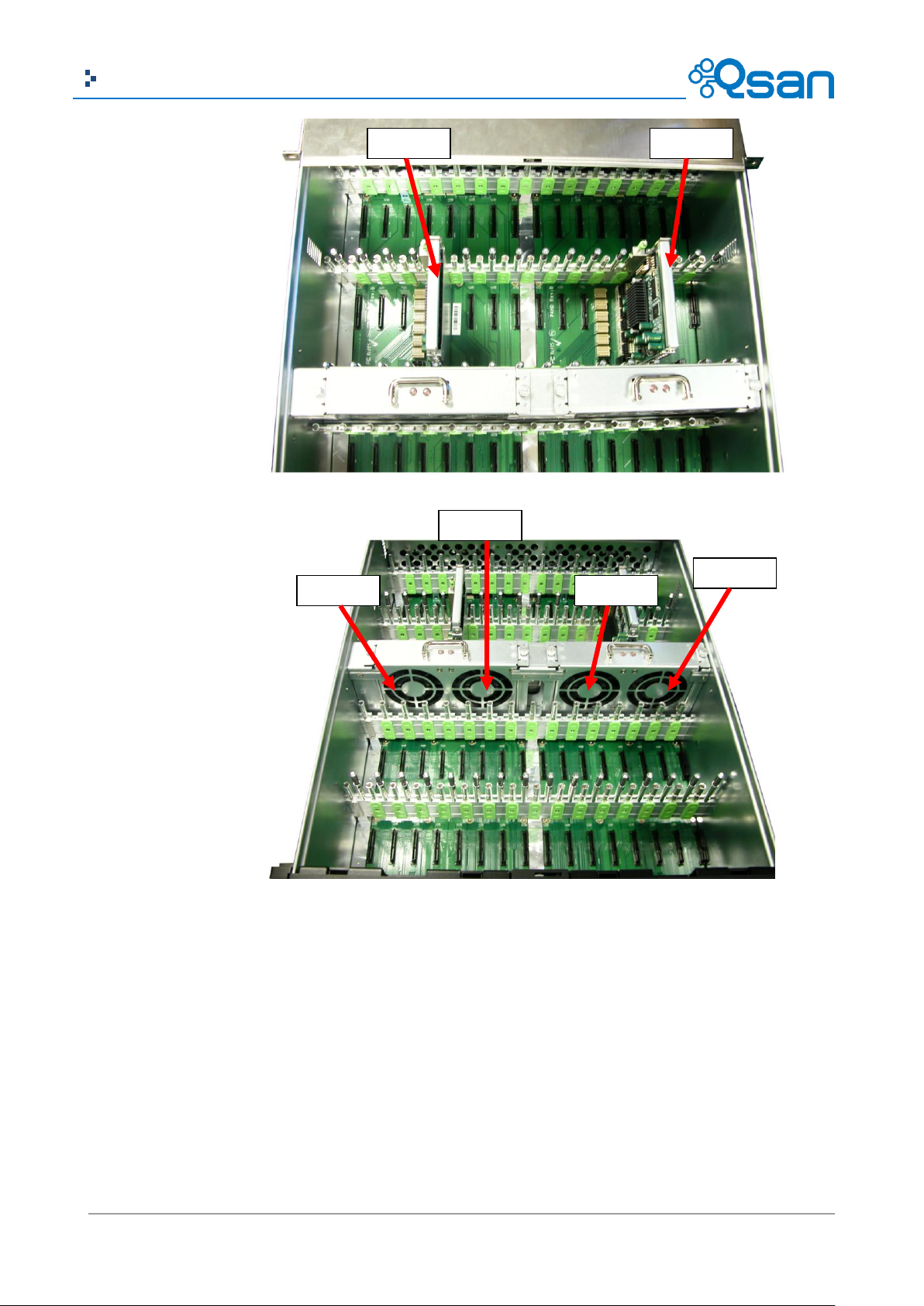
PSU2
Latch
4U24:
4U60:
System Installation and Deployment
AegisSAN Q500 Series:
Using the following instructions to install and deploy the storage system.
Install BBM (Battery Backup Module) for AegisSAN Q500 series models. In all Q500 models,
BBM is not attached to the controller cage.
AegisSAN Q500 2U12 chassis:
。 For 2U12 model, BBM is located inside the right PSU (PSU2 module). Release the PSU2
latch and plug out. Flip to the back side.
Page 47

47
Copyright@2004~2014 Qsan Technology, Inc. All Rights Reserved.
Qsan Document – User Manual
CAUTION:
Please do not touch the golden finger of the PSU when the BBM is connected.
BBM
。 Release the screws. Connect the BBM into the PSU. Be careful that do not touch the
golden finger of the PSU when the BBM is connected.
。 Put it back to PSU, and secure the bracket with screws.
。 Plug it in the chassis.
AegisSAN Q500 3U16 and 4U24 chassis:
。 For 3U16 and 4U24 models, BBM module is located between two controller cages.
BBM module is inserted into the system chassis and connected to the backplane.
。 Release the screws. Plug in the BBM. And then secure the bracket with screws.
Page 48

48
Copyright@2004~2014 Qsan Technology, Inc. All Rights Reserved.
Qsan Document – User Manual
TIP:
The BBM of the AegisSAN Q500 supports controller 1 only.
CAUTION:
When running on dual controller mode, please make sure both controllers have
the same DIMM on each corresponding memory slot. Failing to do so will result
in controller malfunction, which will not be covered by warranty.
CAUTION:
The system is very heavy. It’s recommend that a mechanical lifter or at least
two persons be used to raise and align the system to prevent injury during
installation. Use care when inserting or removing a system into or out of a rack
to prevent the accidental tipping or the rack causing damage or personal injury.
At the rear, check that the Master Controller is in its slot (CTRL 1).
If desired, install the optional Slave Controller in its slot (CTRL 2, only for dual-controller).
Install the Rail Kit onto the unit and insert it into the rack.
Install the Disk Drives.
Connect the management port cable and data port cables on the network plan, the topology
examples are on the following.
Page 49

49
Copyright@2004~2014 Qsan Technology, Inc. All Rights Reserved.
Qsan Document – User Manual
AegisSAN Q500-P10:
AegisSAN Q500-P20:
Page 50

50
Copyright@2004~2014 Qsan Technology, Inc. All Rights Reserved.
Qsan Document – User Manual
AegisSAN Q500-P21:
AegisSAN Q500-F20 / F30:
Page 51

51
Copyright@2004~2014 Qsan Technology, Inc. All Rights Reserved.
Qsan Document – User Manual
CAUTION:
The system is very heavy. It’s recommend that a mechanical lifter or at least
two persons be used to raise and align the system to prevent injury during
installation. Use care when inserting or removing a system into or out of a rack
to prevent the accidental tipping or the rack causing damage or personal injury.
AegisSAN Q500-F21:
AegisSAN V100 Series:
Using the following instructions to install and deploy the storage system.
Install the Rail Kit onto the unit and insert it into the rack.
Install the Disk Drives.
Connect the management port cable and data port cables on the network plan, the topology
examples are on the following.
Page 52

52
Copyright@2004~2014 Qsan Technology, Inc. All Rights Reserved.
Qsan Document – User Manual
AegisSAN V100-P10:
AegisSAN V100-P20:
Page 53

53
Copyright@2004~2014 Qsan Technology, Inc. All Rights Reserved.
Qsan Document – User Manual
AegisSAN V100-F30:
AegisSAN LX Series:
Using the following instructions to install and deploy the storage system.
Install the BBM (Battery Backup Module) in their appropriate controllers if needed. The
following examples show the AegisSAN LX F600Q.
Page 54

54
Copyright@2004~2014 Qsan Technology, Inc. All Rights Reserved.
Qsan Document – User Manual
CAUTION:
When running on dual controller mode, please make sure both controllers have
the same DIMM on each corresponding memory slot. Failing to do so will result
in controller malfunction, which will not be covered by warranty.
CAUTION:
The system is very heavy. It’s recommend that a mechanical lifter or at least
two persons be used to raise and align the system to prevent injury during
installation. Use care when inserting or removing a system into or out of a rack
to prevent the accidental tipping or the rack causing damage or personal injury.
。 BBM supports hot pluggable. Regardless of the system is turned on or off.
。 Remove the cover of BBM.
。 Insert the BBM.
。 Tighten the BBM and use screws to lock the both sides.
At the rear, check that the Master Controller is in its slot (CTRL 1).
If desired, install the optional Slave Controller in its slot (CTRL 2, only for dual-controller).
Install the Rail Kit onto the unit and insert it into the rack.
Install the Disk Drives.
Connect the management port cable and data port cables on the network plan, the topology
examples are on the following.
Page 55

55
Copyright@2004~2014 Qsan Technology, Inc. All Rights Reserved.
Qsan Document – User Manual
AegisSAN LX P400Q:
AegisSAN LX P600Q:
Page 56

56
Copyright@2004~2014 Qsan Technology, Inc. All Rights Reserved.
Qsan Document – User Manual
AegisSAN LX F600Q:
AegisSAN LX F630Q:
Page 57

57
Copyright@2004~2014 Qsan Technology, Inc. All Rights Reserved.
Qsan Document – User Manual
CAUTION:
The system is very heavy. It’s recommend that a mechanical lifter or at least
two persons be used to raise and align the system to prevent injury during
installation. Use care when inserting or removing a system into or out of a rack
to prevent the accidental tipping or the rack causing damage or personal injury.
JBOD Series:
Using the following instructions to install and deploy the storage system.
Install the Rail Kit onto the unit and insert it into the rack.
Install the Disk Drives.
Connect SAS cable to the head unit, the topology examples are on the following.
JBOD J100:
Page 58

58
Copyright@2004~2014 Qsan Technology, Inc. All Rights Reserved.
Qsan Document – User Manual
JBOD J300Q:
Dual controller topology:
For a better data service availability, all the connections among hosts, switches, and the dual
controllers are recommended as redundant as below. The following example shows the AegisSAN
LX P400Q.
Page 59

59
Copyright@2004~2014 Qsan Technology, Inc. All Rights Reserved.
Qsan Document – User Manual
CAUTION:
It may not work when connecting the RS-232 cable for UPS (gray color, phone
jack to DB9 male) to APC Smart UPS directly.
Console and UPS topology:
Connect the console cable and UPS as the following.
。 Using RS-232 cable for console (back color, phone jack to DB9 female) to connect from
controller to management PC directly.
。 Using RS-232 cable for UPS (gray color, phone jack to DB9 male) to connect from
controller to APC Smart UPS serial cable (DB9 female side), and then connect the serial
cable to APC Smart UPS.
Page 60

60
Copyright@2004~2014 Qsan Technology, Inc. All Rights Reserved.
Qsan Document – User Manual
AegisSAN Q500
AegisSAN V100
CAUTION:
Be aware that when Controller Health LED is in RED, please DO NOT plug out
the controller from the system or turn off the power suddenly. This may cause
unrecoverable damage, which will not be covered by warranty.
Attach the power cords and power on the system, and then power on the hosts and the iSNS
Start the configuration.
Power ON / OFF
Power on the System
AegisSAN Q500 Series and AegisSAN V100 Series:
The power button is located at the right front handle. To turn on the system, you may press power
button once. After you turn the power ON, the system performs a booting process which takes a
few minutes.
server (optional for iSCSI environment).
AegisSAN LX Series (2U12 / 3U16 / 4U24):
The power switch is located at the rear of the panel. To turn on the system, you may press power
switch to “|”. After you turn the power ON, the system performs a booting process which takes a
few minutes.
Power off the System
If it becomes necessary to power down the system, it is recommended using a normal, controlled
shutdown form through either the LCM or Web UI to ensure all data is flushed from the cache first.
Page 61

61
Copyright@2004~2014 Qsan Technology, Inc. All Rights Reserved.
Qsan Document – User Manual
AegisSAN Q500 Series:
1. Shutdown using LCM:
At the LCM:
Power off the system using a normal shutdown.
。 Press ENT button.
。 Press (down) twice to show Reboot/Shutdown, and press ENT button.
。 Press (down) once to show Shutdown, and press ENT button.
。 Press (up) once to highlight Yes, and press ENT button.
System shutdown begins. When shutdown process completes, the power LED will turn
off.
2. Shutdown using Web UI:
Using the Web UI:
Select System Maintenance -> Reboot and Shutdown.
Click the Shutdown icon.
System shutdown begins. When shutdown process completes, the power LED will turn
off.
3. Shutdown using Power button:
The power button is located at the right front handle.
Forced shutdown: press and hold for more than 4 seconds. The power will be cut off
immediately.
Graceful shutdown: press one to initialize graceful shutdown. Press 2nd time within 4
seconds to confirm and start graceful shutdown. If there is no 2nd press within 4
seconds, disable graceful shutdown and return to normal operating mode.
4. Shutdown using QCentral Client:
Login QCentral Client:
Select Maintenance -> Reboot and Shutdown.
Click the Shutdown icon.
System shutdown begins. When shutdown process completes, the power LED will turn
off.
AegisSAN V100 Series:
1. Shutdown using Web UI:
Using the Web UI:
Select System Maintenance -> Reboot and Shutdown.
Click the Shutdown icon.
System shutdown begins. When shutdown process completes, the power LED will turn
off.
Page 62

62
Copyright@2004~2014 Qsan Technology, Inc. All Rights Reserved.
Qsan Document – User Manual
2. Shutdown using Power button:
The power button is located at the right front handle.
Forced shutdown: press and hold for more than 4 seconds. The power will be cut off
immediately.
Graceful shutdown: press one to initialize graceful shutdown. Press 2nd time within 4
seconds to confirm and start graceful shutdown. If there is no 2nd press within 4
seconds, disable graceful shutdown and return to normal operating mode.
3. Shutdown using QCentral Client:
Login QCentral Client:
Select Maintenance -> Reboot and Shutdown.
Click the Shutdown icon.
System shutdown begins. When shutdown process completes, the power LED will turn
off.
AegisSAN LX Series:
1. Shutdown using LCM:
At the LCM:
Power off the system using a normal shutdown.
。 Press ENT button.
。 Press (down) twice to show Reboot/Shutdown, and press ENT button.
。 Press (down) once to show Shutdown, and press ENT button.
。 Press (up) once to highlight Yes, and press ENT button.
System shutdown begins. When the System Shutdown message is displayed, turn the
power switch to OFF “O”.
2. Shutdown using Web UI:
Using the Web UI:
Select System Maintenance -> Reboot and Shutdown.
Click the Shutdown icon.
System shutdown begins. When the System Shutdown message is displayed, turn the
power switch to OFF “O”.
3. Shutdown using QCentral Client:
Login QCentral Client:
Select Maintenance -> Reboot and Shutdown.
Click the Shutdown icon.
System shutdown begins. When the System Shutdown message is displayed, turn the
power switch to OFF “O”.
Page 63

63
Copyright@2004~2014 Qsan Technology, Inc. All Rights Reserved.
Qsan Document – User Manual
Quick Setup
3
Management Interfaces
There are several management methods to manage the storage system, described on the
following.
Serial Console
Use console cable (NULL modem cable) to connect from console port of the storage system to RS
232 port of the management PC. The console settings are on the following:
Baud rate: 115200, 8 data bit, no parity, 1 stop bit, and no flow control.
Terminal Type: vt100
The initial defaults for administrator login are:
Management IP Address: 192.168.1.234
User Name: admin
Password: 1234
Secure Shell Remote Access
SSH (secure shell) software is required for remote login. The SSH client software is available at the
following web site:
SSH Tectia Client: http://www.ssh.com/
PuTTY: http://www.chiark.greenend.org.uk/
The default management IP address is 192.168.1.234/255.255.255.0, please configure your
computer IP address at the same subnet of the system (e.g.: 192.168.1.1/255.255.255.0). The
remote control settings are on the following:
Host IP: <IP Address> (e.g.: 192.168.1.234)
User Name: admin
Password: 1234
Page 64

64
Copyright@2004~2014 Qsan Technology, Inc. All Rights Reserved.
Qsan Document – User Manual
TIP:
Qsan system supports SSH for remote access only. When using SSH, the IP
address and password are required for login.
Function
Description
System Info.
Display system information including firmware version and amount of
RAM.
Alarm Mute
Mutes an alarm after an error occurs.
Reset/Shutdown
Reset or shutdown the system.
Quick Install
Provide quick steps to create a volume.
Volume Wizard
Provide smart steps to create a volume.
View IP Setting
Display current IP address, subnet mask, and gateway.
Change IP config
Set IP address, subnet mask, and gateway. There are 2 options: DHCP
(Get IP address from DHCP server) or static IP.
Enc. Management
Shows the enclosure data for physical disk temperatures, fan status, and
power supply status.
Reset to Default
Reset the system to default settings. The default resets include:
Management IP Address: 192.168.1.234
User Name: admin
Password: 1234
192.168.1.234
Qsan P400Q-D424 ←
LCM
After booting up the system, the following screen shows management port IP and model name.
Take an example of AegisSAN LX P400Q-D424.
To access the LCM options, use the ENT (Enter) button, ESC (Escape) button, (up) and (down)
to scroll through the functions.
This table describes the function of each item.
WARNING or ERROR events displayed on the LCM are automatically filtered by the LCM default
filter. The filter setting can be changed in the Web UI under System Configuration -> Log and Alert
Settings.
Page 65

65
Copyright@2004~2014 Qsan Technology, Inc. All Rights Reserved.
Qsan Document – User Manual
Main
L1
L2
L3
L4
L5
<IP Addr>
Qsan
<Model>
System Info.
Firmware Version
<n.n.n>
RAM Size <nnnn> MB
Alarm Mute
Yes No
Reset/
Shutdown
Reset
Yes No
Shutdown
Yes No
Quick Install
(only available if
not already set)
<RAID 0
RAID 1
RAID 3
RAID 5
RAID 6
RAID 0+1>
nnn GB
Apply The
Config
Yes No
Volume Wizard
(only available if
not already set)
Local
<RAID 0
RAID 1
RAID 3
RAID 5
RAID 6
RAID 0+1>
Use default
algorithm
Volume Size
<nnn> GB
Apply The
Config
Yes No
JBOD <n>
<RAID 0
RAID 1
RAID 3
RAID 5
RAID 6
RAID 0+1>
New n disk
<nnn> GB
Adjust Volume
Size
Apply The
Config
Yes No
View IP Setting
IP Config
<Static IP /
DHCP / BOOTP>
IP Address
<192.168.001.234>
IP Subnet Mask
<255.255.255.0>
IP Gateway
<xxx.xxx.xxx.xxx>
Change IP Config
DHCP
Yes No
BOOTP
Yes No
Static IP
IP Address
Adjust IP
address
IP Subnet Mask
Adjust Submask
IP
IP Gateway
Adjust Gateway
IP
Apply IP Setting
Yes No
Enc. Management
Phy. Disk Temp.
Local
Slot <n>: <nn>
(C)
Cooling
Local
FAN<n>:
<nnnnn> RPM
Power Supply
Local
PSU<n>:
<status>
Reset to Default
Yes No
This table displays the LCM menu hierarchy.
USB LCM is developed because of security concern and adding more mobility and flexibility. Only
AegisSAN Q500 series support USB LCM. Several AegisSAN Q500 systems can share one USB LCM.
It can further save your costs. All the functions provided by USB LCM are the same as the original
Page 66
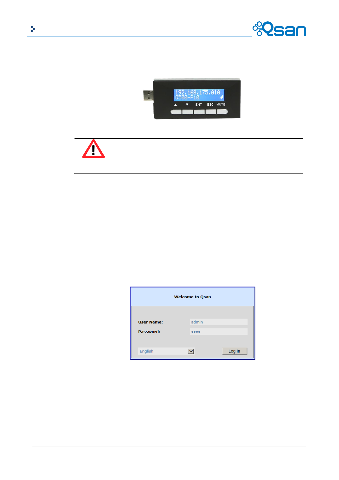
66
Copyright@2004~2014 Qsan Technology, Inc. All Rights Reserved.
Qsan Document – User Manual
CAUTION:
To prevent data loss, when powering down the storage system, it is
recommended to execute Reset/Shutdown -> Shutdown -> Yes to flush the
data from the cache to the physical disks.
LCM introduced in previous section. Please be aware to remove the USB LCM before adding the
front bezel.
Web UI
Qsan storage system supports graphic user interface operation. It supports most common web
browsers. Be sure to connect the LAN cable to the management port of the system.
The default management IP address is 192.168.1.234/255.255.255.0, please configure your
computer IP address at the same subnet of the system (e.g.: 192.168.1.1/255.255.255.0). And then
enter the IP address into your browser to display the authentication screen.
http://<IP Address> (e.g.: http://192.168.1.234)
To access the Web UI, you have to enter a user name and password. The initial defaults for
administrator login are:
User Name: admin
Password: 1234
Page 67

67
Copyright@2004~2014 Qsan Technology, Inc. All Rights Reserved.
Qsan Document – User Manual
TIP:
The Host Port Configuration menu bar option is only visible when the controller
has multiple interfaces. The iSCSI Configuration menu bar option is only visible
when the controller has iSCSI ports.
Menu Bar
Options
Indicators
and Icons
Operation
Area
When the password has been verified, the home page is displayed. The following examples show
the AegisSAN LX P400Q-D212.
Choose the functions from the Menu Bar on the left side of the window to make any configuration
changes.
Page 68

68
Copyright@2004~2014 Qsan Technology, Inc. All Rights Reserved.
Qsan Document – User Manual
Icon
Description
RAID indicator:
Green: All RAID groups are functioning.
Red: A RAID group is degraded or has failed.
Temperature indicator:
Green: Temperature is normal.
Red: Temperature is too high.
Voltage indicator:
Green: Voltage values are normal.
Red: Voltage values are out of range.
UPS indicator:
Green: UPS is functioning or no UPS is connected.
Red: UPS connection has failed.
Fan indicator:
Green: Fan is working well.
Red: Fan failed.
Power indicator:
Green: Power supplies are connected and working well.
Red: A power supply has failed or is no longer connected.
Dual controller indicator:
Green: Dual controllers are active and working well.
Orange: One of the dual controllers has failed.
Return to home page.
Logout of the management web UI.
Mute alarm beeper.
TIP:
If the status indicators in Internet Explorer (IE) are displayed in gray, but not in
blinking red, please enable Tools -> Internet Options -> Advanced -> Play
animations in webpages options in IE. The default value is enabled, but some
applications disable it.
There are up to seven indicators and three icons at the top-right corner. The last indicator (Dual
controller) is only visible when two controllers are installed.
This table describes the indicators and icons.
How to Use the Guided Configurations
To help users get started quickly, two guided configuration tools are available in the Web UI and
LCM. Quick Installation guides you a easy way to create a volume. Volume Creation Wizard
Page 69

69
Copyright@2004~2014 Qsan Technology, Inc. All Rights Reserved.
Qsan Document – User Manual
provides a smarter policy to help users to create a volume. If you are an advanced user, you can
skip these steps.
Quick Installation Tool
This tool guides you through the process of setting up basic array information, configuring network
settings, and the creation of a volume on the storage system. Please make sure that it has some
free hard drives installed in the system. SAS drivers are recommended.
1. Click Quick Installation from the menu bar.
2. Enter a System Name and set up the Date and Time. Click Next button to proceed.
Page 70

70
Copyright@2004~2014 Qsan Technology, Inc. All Rights Reserved.
Qsan Document – User Manual
3. Confirm or change the management port IP address and DNS server. If the default HTTP,
HTTPS, and SSH port numbers are not allowed on your network, they can be changed here as
well.
Page 71

71
Copyright@2004~2014 Qsan Technology, Inc. All Rights Reserved.
Qsan Document – User Manual
4. For iSCSI Configurations, use this step to set up the data port iSCSI IP address, and then click
Next button.
Page 72

72
Copyright@2004~2014 Qsan Technology, Inc. All Rights Reserved.
Qsan Document – User Manual
5. Choose a RAID Level. The number in the brackets is the maximum capacity at the RAID level.
This step utilizes all drives in the storage system as well as any JBOD expansion arrays
present. This option allows the selection of the RAID type and the number of drives in each
array.
Page 73

73
Copyright@2004~2014 Qsan Technology, Inc. All Rights Reserved.
Qsan Document – User Manual
6. Verify all items, and then click Finish button to complete the quick installation.
Page 74
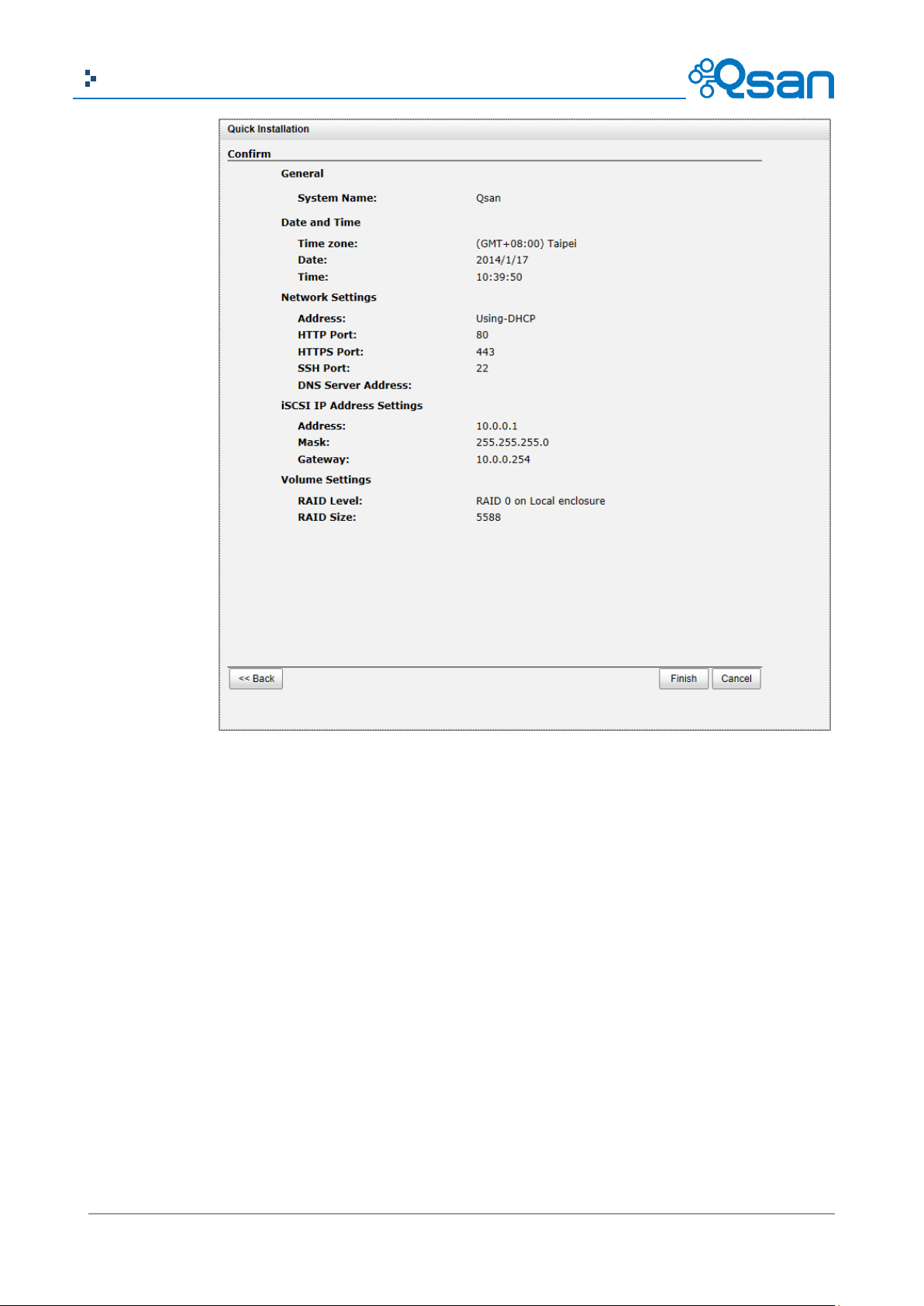
74
Copyright@2004~2014 Qsan Technology, Inc. All Rights Reserved.
Qsan Document – User Manual
The iSCSI information is only displayed when iSCSI controllers are used. Use Back button to return
to a previous page to change any setting.
Volume Creation Wizard
The Volume Creation Wizard provides a smarter policy to determine all possibilities and volume
sizes in the different RAID levels that can be created using the existing free drives. It provides:
Largest capacity for each RAID level from which to choose.
The fewest number of drives for each RAID level / volume size.
This way, after choosing RAID level, you may find that some drives are still available (free status).
This phenomenon is the result of using smart design. Take an example, user chooses the RAID 5
level and the system has 12*200GB + 4*80GB free drives inserted. Generally, if using all 16 drives
for a RAID 5 group, the maximum size of volume is (16-1)*80GB = 1200GB. This wizard provides a
Page 75

75
Copyright@2004~2014 Qsan Technology, Inc. All Rights Reserved.
Qsan Document – User Manual
smarter check and searches the most efficient way of using free drives. It uses 200GB drives only
to provide (12-1)*200GB = 2200GB capacity, the volume size is larger and less drives.
1. Click Volume Creation Wizard from the menu bar.
2. Choose a RAID Level. The number in the brackets is the maximum capacity at the RAID level.
3. Select the default option Maximize the size of the RAID group or manual option Select the
number of disks to use. From the drop-down list, select either the RAID Group capacity
combination desired. Click Next button to proceed.
Page 76

76
Copyright@2004~2014 Qsan Technology, Inc. All Rights Reserved.
Qsan Document – User Manual
4. Enter the Volume Size (GB) desired that is less than or equal to the default available size
shown. Then click Next button.
5. Use LBA 64 support? It depends on the operation system.
6. Finally, verify the selections and click Finish button if they are correct.
Page 77

77
Copyright@2004~2014 Qsan Technology, Inc. All Rights Reserved.
Qsan Document – User Manual
The volume is created and named by the system automatically. It is available to use now.
Page 78

78
Copyright@2004~2014 Qsan Technology, Inc. All Rights Reserved.
Qsan Document – User Manual
Basic Configuration
4
Menu Bar
L1
L2, Button or Menu
System
Configuration
System Settings
System Name / Date and Time / System Indication
Network Settings
MAC Address / IP Address / DNS Server Address / Service Ports
Login Settings
Login Options / Admin Password / User Password
Email Notification
Settings
Email Settings / Send Test Mail
Log and Alert Settings
SNMP Trap Settings / Windows Messenger / Syslog Server Settings /
Admin Interface and Front Display Alerts / Device Buzzer
iSCSI Configuration
(This option is only
visible when the
controller has iSCSI
ports.)
Host Configuration
(This option is only
visible when the
controller has
multiple
interfaces.)
Network Setup
Show information for: < Controller 1 | Controller 2 >
Options: [iSCSI Bonding Settings | Delete iSCSI Bonding] / Set VLAN ID
/ iSCSI IP Address Settings / Make Default Gateway / [Enable | Disable]
Jumbo Frames / Ping Host / Reset Port
Entity and iSNS
Settings
Entity Name / iSNS IP Address
iSCSI Node
Show information for: < Controller 1 | Controller 2 >
Options: Authentication Method / Change Portal / Rename Alias /
Users
Active Sessions
Show information for: < Controller 1 | Controller 2 >
Connection Details / Disconnect
CHAP Accounts
Create User
Options: Modify User Information / Delete User
Fibre Channel
(This option is only
visible when the
controller has FC
ports.)
Show information for: < Controller 1 | Controller 2 >
Clear All Counters
Options: Change Link speed / Change Connection Mode / Node
Configuration / Clear Counters
Volume
Configuration
Physical Disks
Show disk for: < -Local- | -JBODn- >
Show disk size in: < (GB) | (MB) >
Disk Health Check / Disk Check Report
Options: Set Free Disk / Set Global Spare / Set Local Spare / Set
Dedicated Spare / Upgrade / Disk Scrub / Read Error Cleared / Turn
[on | off] the Indication LED / More information
RAID Groups
Show RAID size in: < (GB) | (MB) >
Create
Options: Migrate RAID Level / Move RAID Level / [Activate |
Deactivate] / Verify Parity / Delete / Change Preferred Controller /
Change RAID Options / Add RAID Set / Add Policy / More information
RAID Set options: Remove / Move RAID Level / List Disks
RAID Group Policy options: Delete / Modify
Virtual Disks
Create / Cloning Options
Options: Extend / Set SSD Caching / Verify Parity / Delete / Set
Properties / Space Reclamation / Attach LUN / Detach LUNs / List
LUNs / Set Clone / Set Snapshot Space / Cleanup Snapshots / Take a
Snapshot / Scheduled Snapshots / List Snapshots / More information
Snapshots
Set Snapshot Space / Scheduled Snapshots / Take a Snapshot /
Cleanup Snapshots
Interface Hierarchy
This table describes the hierarchy of the web GUI.
Page 79

79
Copyright@2004~2014 Qsan Technology, Inc. All Rights Reserved.
Qsan Document – User Manual
Options: Set Quota / Rollback / Delete
Logical Units
Attach LUN
Options: Detach LUN
QReplicas
Create / Rebuild / QReplica Options / Shaping Setting Configuration
Options: Start / Stop / Set Task Shaping / Add Path / Delete Path /
Schedule / Delete / Add Connection / Delete Connection
Task Path options: Add Connection / Delete Connection / Delete
Enclosure
Management
Hardware
Monitor
Show information for: < -Local- | -JBODn- >
Temperature (Internal)/(Case): < (C) / (F) >
Controller 1 Monitors / Controller 2 Monitors / Backplane
Options: Auto Shutdown
UPS
UPS Type / Shutdown Battery Level (%) / Shutdown Delay (Seconds) /
Shutdown UPS / UPS Status / UPS Battery Level
SES
[Enable | Disable]
S.M.A.R.T.
Show information for: < -Local- | -JBODn- >
Temperature (Internal)/(Case): < (C) | (F) >
System
Maintenance
System
information
Download System Information
Event log
Event Log Level to Show: < Information | Warning | Error >
Download / Mute Buzzer / Clear
Upgrade
Controller Module Firmware Update / JBOD Firmware Update /
Controller Mode / SSD Caching License
Firmware
Synchronization
(This option is only
visible when dual
controllers are
inserted.)
Apply
Reset to Factory
Default
Reset
Configuration Backup
Import or Export / Import File
Volume Restoration
Options: Restore
Reboot and
Shutdown
Reboot / Shutdown
Reboot options: [Both Controller 1 and Controller 2 | Controller 1 |
Controller 2]
Performance
Monitor
Disk
Show disk for: < -Local- | -JBODn- >
iSCSI
Controller 1 / Controller 2
Fibre Channel
(This option is only
visible when the
controller has FC
ports.)
Controller 1 / Controller 2
Quick Installation
Step 1 / Step 2 / Step 3 / Step 4 / Confirm
Volume Creation
Wizard
Step 1 / Step 2 / Step 3 / Confirm
System Configuration
The System Configuration menu option is for accessing the System Settings, Network Settings,
Login Settings, Email Notification Settings, and Log and Alert Settings option tabs.
System Settings
The System Settings tab is used to setup the system name and date. The default system name is
composed of the model name and the serial number of this system.
Page 80

80
Copyright@2004~2014 Qsan Technology, Inc. All Rights Reserved.
Qsan Document – User Manual
The options are available on this tab:
System Name: Change the System Name, highlight the old name and type in a new one.
Date and Time: Change the current date, time and time zone settings, check Change Date
and Time. The changes can be done manually or synchronized from an NTP (Network Time
Protocol) server.
System Identification: Flash the status light on the front display for locating this system in
the racks, click OK button. To Stop flashing the status light on the front display, click OK
button again.
When it is done, click Apply button.
Network Settings
The Network Settings tab is used to view the MAC address and change basic network settings.
Page 81

81
Copyright@2004~2014 Qsan Technology, Inc. All Rights Reserved.
Qsan Document – User Manual
The options are available on this tab:
Enable dual management ports: This is for dual controller models. Check it to enable dual
MAC Address: Display the MAC address of the management port in the system.
IP Address: The option can change IP address for remote administration usage. There are
Service Ports: If the default port numbers of HTTP, HTTPS and SSH are not allowed on the
When it is done, click Apply button.
Login Settings
The Login Settings tab is used to control access to the storage system. For the security reason, set
the auto logout option or set the limit access of one administrator at a time. The other options can
management ports.
three options: DHCP, BOOTP and Specify a Static IP Address. DNS Server Address: If
necessary, the IP address of DNS server can be entered or changed here.
network, they can be changed here.
change the Admin and User passwords.
Page 82

82
Copyright@2004~2014 Qsan Technology, Inc. All Rights Reserved.
Qsan Document – User Manual
TIP:
Please make sure the DNS server IP is well-setup in System Configuration ->
Network Settings. So the event notification emails can be sent successfully.
The options are available on this tab:
Auto Logout: When the auto logout option is enabled, you will be logged out of the admin
interface after the time specified. There are Disable (default), 5 minutes, 30 minutes and 1
hour options.
Login Lock: When the login lock is enabled, the system allows only one user to login to the
web UI at a time. There are Disable (default) and Enable options.
Change Admin Password: Check it to change administrator password. The maximum length
of password is 12 alphanumeric characters.
Change User Password: Check it to change user password. The maximum length of password
is 12 alphanumeric characters.
When it is done, click Apply button.
Email Notification Settings
The Email Notification Settings tab is used to enter up to three email addresses for receiving the
event notifications. Fill in the necessary fields and click Send Test Email button to test whether it is
available. Some email servers will check the mail-from address and need the SMTP relay settings
for authentication.
Page 83
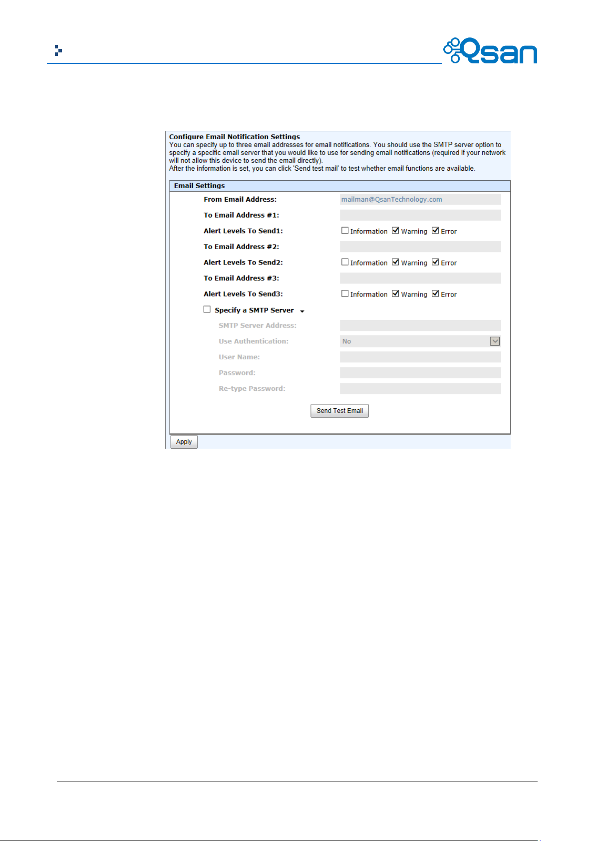
83
Copyright@2004~2014 Qsan Technology, Inc. All Rights Reserved.
Qsan Document – User Manual
You can also select which levels of event logs which you would like to receive. The default setting
only includes Warning and Error event logs.
When it is done, click Apply button.
Log and Alert Settings
The Log and Alert Settings tab is used to setup SNMP traps (for alerting via SNMP), pop-up
messages via Windows messenger (not MSN or Skype), alerts via the syslog protocol, the pop-up
alerts and alerts on the front display. The device buzzer is also managed here.
Page 84

84
Copyright@2004~2014 Qsan Technology, Inc. All Rights Reserved.
Qsan Document – User Manual
The options are available on this tab:
SNMP Trap Settings: It allows up to three SNMP trap addresses. The default community
setting is public. You can check the alert levels which you would like to receive. The default
setting only includes Warning and Error event logs. If necessary, click Download to get the
MIB file for importing to the SNMP client tool.
There are many SNMP tools available on the internet.
。 SNMPc: http://www.snmpc.com/
。 Net-SNMP: http://net-snmp.sourceforge.net/
Windows Messenger: You must enable the Messenger service in Windows (Start -> Control
Panel -> Administrative Tools -> Services -> Messenger). It allows up to three host
addresses. The same, you can check the alert levels which you would like to receive.
System Server Settings: Fill in the host address and the facility for syslog service. The default
UDP port is 514. You can also check the alert levels here.
There are some syslog server tools available on the internet for Windows.
。 WinSyslog: http://www.winsyslog.com/
。 Kiwi Syslog Daemon: http://www.kiwisyslog.com/
Page 85
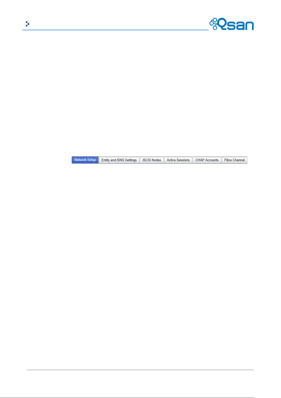
85
Copyright@2004~2014 Qsan Technology, Inc. All Rights Reserved.
Qsan Document – User Manual
Most UNIX systems built in syslog daemon.
Admin Interface and Front Display Alerts: You can check the alert levels which you would
like to have pop-up message in the Web UI and show on front display. The default setting for
admin interface is none while the default setting for shown on the front display includes
Warning and Error event logs.
Device Buzzer: Check it to disable the device buzzer. Uncheck it to activate the device buzzer.
When it is done, click Apply button.
Host Port / iSCSI Configuration
The Host port / iSCSI Configuration menu option is for accessing the Network Setup, Entity and
iSNS Settings, iSCSI Nodes, Active Sessions, CHAP Account and Fibre Channel (This option is only
visible when the controller has Fibre Channel ports) option tabs.
Network Setup
The Network Setup tab is used to change IP addresses of iSCSI data ports. The various controllers
have different iSCSI ports, list on the following:
AegisSAN Q500:
Q500-P10: 6 x GbE iSCSI ports per controller.
Q500-P20: 2 x 10GbE iSCSI ports + 2 x GbE iSCSI ports per controller.
Q500-P21: 2 x 10GbE iSCSI ports + 2 x GbE iSCSI ports per controller.
Q500-F20: 2 x GbE iSCSI ports per controller.
Q500-F21: 2 x GbE iSCSI ports per controller.
Q500-F30: 2 x GbE iSCSI ports per controller.
AegisSAN V100:
V100-P10: 6 x GbE iSCSI ports per controller.
V100-P20: 2 x 10GbE iSCSI ports + 6 x GbE iSCSI ports per controller.
V100-F30: 6 x GbE iSCSI ports per controller.
AegisSAN LX:
P400Q: 6 x GbE iSCSI ports per controller.
P600Q: 2 x 10GbE iSCSI ports + 2 x GbE iSCSI port per controller.
F600Q: 2 x GbE iSCSI ports per controller.
Page 86

86
Copyright@2004~2014 Qsan Technology, Inc. All Rights Reserved.
Qsan Document – User Manual
F630Q: 2 x GbE iSCSI ports per controller.
These network ports must be assigned IP addresses then they can be used. For better
performance or fault tolerance reason, they can be bonding as Trunking or LACP. These bonding
network ports share a single IP address. The following example shows the P400Q series (6 x GbE
iSCSI ports).
This figure shows six iSCSI data ports. These data ports are set up with a static IP address. For the
other controllers, that can be set up the same way.
The options are available on this tab:
▼ -> iSCSI Bonding Settings: The default mode of each iSCSI data port is individually
connected without any bonding. Trunking and LACP (Link Aggregation Control Protocol)
settings can be setup here. At least two iSCSI data ports must be checked for iSCSI bonding.
。 Trunking: Configures multiple iSCSI ports to be grouped together into one in order to
increase the connection speed beyond the limit of a single iSCSI port.
。 LACP: The Link Aggregation Control Protocol is part of IEEE specification 802.3ad that
allows bonding several physical ports together to form a single logical channel. LACP
Page 87

87
Copyright@2004~2014 Qsan Technology, Inc. All Rights Reserved.
Qsan Document – User Manual
TIP:
If iSCSI ports are assigned with VLAN ID before creating aggregation takes place,
aggregation will remove VLAN ID. You need to repeat the steps to set VLAN ID
for the aggregation group.
allows a network switch to negotiate an automatic bundle by sending LACP packets to
the peer. The advantages of LACP are that it increases bandwidth usage and it
automatically performs a failover when the link status fails on a port.
▼ -> Set VLAN ID: VLAN is a logical grouping mechanism implemented on switch device.
VLANs are collections of switching ports that comprise a single broadcast domain. It allows
network traffic to flow more efficiently within these logical subgroups. Please consult your
network switch user manual for VLAN setting instructions. Most of the work is done at the
switch part. All you need to do is to make sure that your VLAN ID of iSCSI port matches that
of switch port. If your network environment supports VLAN, you can use this function to
change the configurations. Fill in VLAN ID and Priority settings to enable VLAN.
。 VLAN ID: VLAN ID is a 12-bit number. Its range is from 2 to 4094, while 0, 1, and 4095
are reserved for special purposes.
。 Priority: The PCP (Priority Code Point) is a 3-bit number and reserved for QoS. The
definition complies with IEEE 802.1p protocol, ranging from 0 to 7, with 0 as the
default value. In normal cases, you don't need to set this value. Using the default will
do just fine.
▼ -> iSCSI IP Address Settings: It can assign an iSCSI IP address of the iSCSI data port. There
are two options: Use DHCP to acquire an IP address automatically or Specify a Static IP
Address to set the IP address manually.
Page 88

88
Copyright@2004~2014 Qsan Technology, Inc. All Rights Reserved.
Qsan Document – User Manual
CAUTION:
VLAN ID, jumbo frames for both the switching hub and HBA on host must be
enabled. Otherwise, the LAN connection cannot work properly.
▼ -> Make Default Gateway: Set the gateway of the IP address as default gateway. There
can be only one default gateway. To remove the default gateway, click ▼ -> Remove
Default Gateway.
▼ -> Enable jumbo frames: It can enable the MTU (Maximum Transmission Unit) size. The
maximum jumbo frame size is 3900 bytes. To disable jumbo frames, click ▼ -> Disable
Jumbo Frames.
▼ -> Ping host: It can verify the port connection from a target to the corresponding host
data port. Input the host’s IP address and click Start button. The system will display the ping
result. Or click Stop button to stop the test.
▼ -> Reset Port: If the behavior of the port is abnormal, try to reset port to make it normal.
Page 89

89
Copyright@2004~2014 Qsan Technology, Inc. All Rights Reserved.
Qsan Document – User Manual
Entity and iSNS Settings
The Entity and iSNS Settings tab is used to view the entity name of the system, and setup iSNS IP
for the iSNS (Internet Storage Name Service) protocol. It allows automated discovery,
management and configuration of iSCSI devices on a TCP/IP network. To use iSNS, an iSNS server
needs to be added to the SAN. When this is done, the iSNS server IP address must be added to the
storage system for iSCSI initiator service to send queries to it.
To make changes, enter the Entity Name and the iSNS IP Address, and then click Apply button.
iSCSI Nodes
The iSCSI Nodes tab is used to view the target name for iSCSI initiator. The various controllers
support different number of multiple nodes, list on the following:
AegisSAN Q500:
Q500-P10: Up to 64 multiple nodes per controller.
Q500-P20: Up to 64 multiple nodes per controller.
Q500-P21: Up to 64 multiple nodes per controller.
Q500-F20: Up to 32 multiple nodes per controller.
Q500-F21: Up to 32 multiple nodes per controller.
Q500-F30: Up to 32 multiple nodes per controller.
AegisSAN V100:
V100-P10: Up to 32 multiple nodes per controller.
V100-P20: Up to 32 multiple nodes per controller.
V100-F30: Up to 32 multiple nodes per controller.
AegisSAN LX:
P400Q: Up to 128 multiple nodes per controller.
P600Q: Up to 128 multiple nodes per controller.
F600Q: Up to 32 multiple nodes per controller.
F630Q: Up to 32 multiple nodes per controller.
Page 90

90
Copyright@2004~2014 Qsan Technology, Inc. All Rights Reserved.
Qsan Document – User Manual
TIP:
A CHAP account must be added before you can use this authentication method.
Please refer to CHAP Accounts session to create an account if none exists.
The following example shows the AegisSAN LX P400Q series (up to 128 multiple nodes).
The options are available on this tab:
▼ -> Authentication Method: CHAP (Challenge Handshake Authentication Protocol) is a
strong authentication method used in point-to-point for user login. It’s a type of
authentication in which the authentication server sends the client a key to be used for
encrypting the username and password. CHAP enables the username and password to
transmit in an encrypted form for protection.
To use CHAP authentication, please follow the procedures.
。 Select one of nodes from one controller.
。 Chick ▼ -> Authentication Method.
。 Select CHAP from the drop-down list.
。 Click OK button.
Page 91

91
Copyright@2004~2014 Qsan Technology, Inc. All Rights Reserved.
Qsan Document – User Manual
。 Chick ▼ -> User.
。 Select CHAP user(s) which will be used. It can be more than one, but it must be at least
one CHAP to enable on the node.
。 Click OK button.
To disable CHAP authentication, please follow the procedures.
。 Select the node which wants to disable CHAP.
。 Chick ▼ -> Authentication Method.
。 Change it to None from the drop-down list.
。 Click OK button.
▼ -> Change Portal: Use this iSCSI node option to change the network ports available.
。 Select one of nodes from one controller.
。 Chick ▼ -> Change Portal.
。 Select the network ports that you would like to be available for this iSCSI node.
Page 92
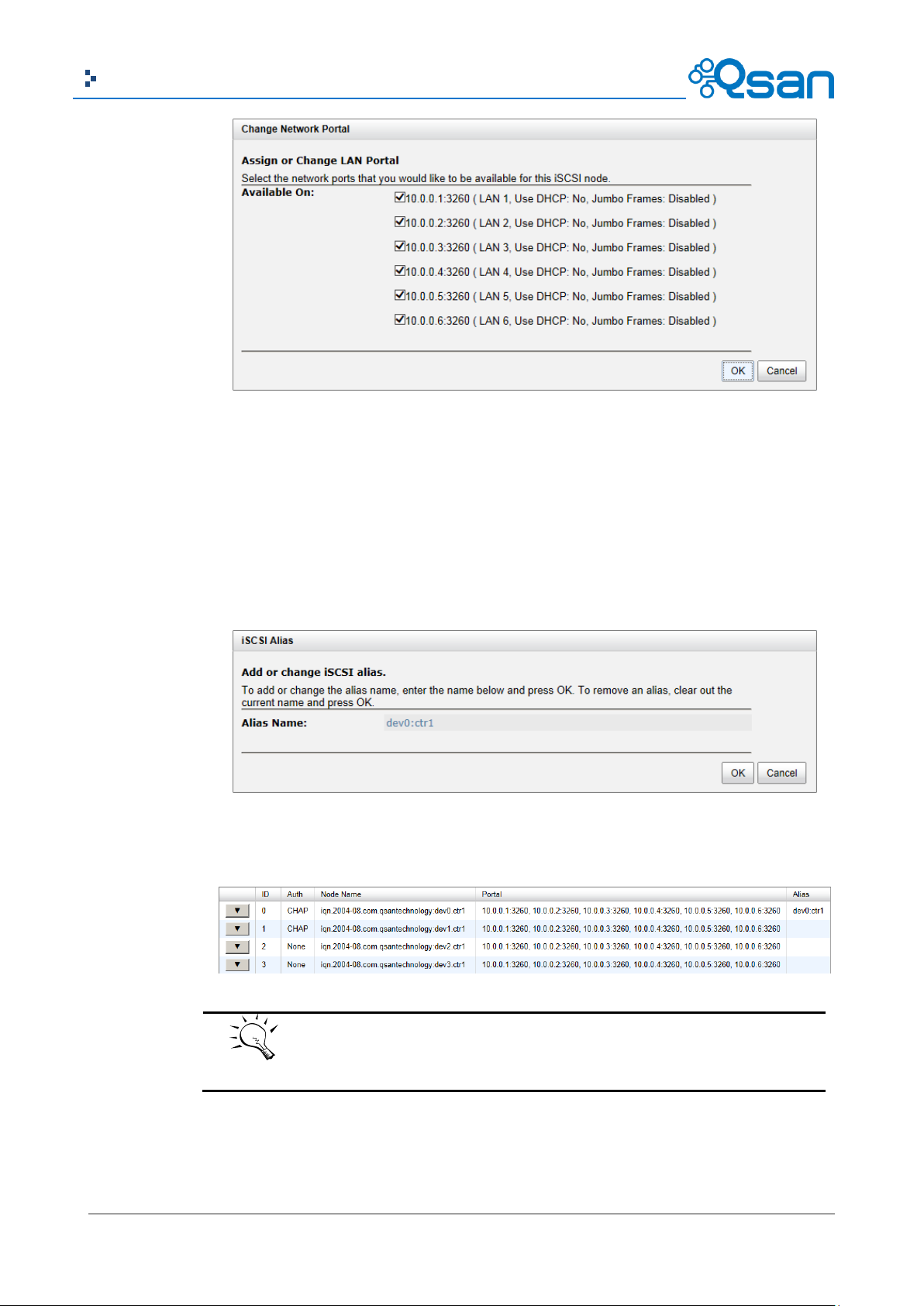
92
Copyright@2004~2014 Qsan Technology, Inc. All Rights Reserved.
Qsan Document – User Manual
TIP:
After setting CHAP, the host initiator should be set with the same CHAP
account. Otherwise, the host cannot connect to the volume.
。 Click OK button.
▼ -> Rename Alias: Use this option to add or change iSCSI alias.
。 Select one of nodes from one controller.
。 Chick ▼ -> Rename Alias.
。 Enter the Alias Name. Leave it empty to remove the alias.
。 Click OK button.
After creating an alias, it is displayed at the end of the portal information.
Page 93

93
Copyright@2004~2014 Qsan Technology, Inc. All Rights Reserved.
Qsan Document – User Manual
Column Name
Description
TSIH
TSIH (Target Session Identifying Handle) is used for this active session.
Initiator Name
It displays the host computer name.
Target Name
It displays the controller name.
InitialR2T
InitialR2T (Initial Ready to Transfer) is used to turn off either the use of a
unidirectional R2T command or the output part of a bidirectional
command. The default value is Yes.
Immed. data
Immed. data (Immediate Data) sets the support for immediate data
between the initiator and the target. Both must be set to the same
setting. The default value is Yes.
MaxDataOutR2T
MaxDataOutR2T (Maximum Data Outstanding Ready to Transfer)
Active Sessions
The Active Session tab is used to display all currently active iSCSI sessions and their connection
information. The various controllers support different number of sessions, list on the following:
AegisSAN Q500:
Q500-P10: Up to 256 sessions per controller.
Q500-P20: Up to 256 sessions per controller.
Q500-P21: Up to 256 sessions per controller.
Q500-F20: Up to 64 sessions per controller.
Q500-F21: Up to 64 sessions per controller.
Q500-F30: Up to 64 sessions per controller.
AegisSAN V100:
V100-P10: Up to 256 sessions per controller.
V100-P20: Up to 256 sessions per controller.
V100-F30: Up to 64 sessions per controller.
AegisSAN LX:
P400Q: Up to 1024 sessions per controller.
P600Q: Up to 1024 sessions per controller.
F600Q: Up to 128 sessions per controller.
F630Q: Up to 128 sessions per controller.
This table shows the column descriptions. Most of the options are standard parameters used in
the negotiation between the initiator and target when an iSCSI connection is created.
Page 94

94
Copyright@2004~2014 Qsan Technology, Inc. All Rights Reserved.
Qsan Document – User Manual
determines the maximum number of outstanding ready to transfer per
task. The default value is 1.
MaxDataBurstLen
MaxDataBurstLen (Maximum Data Burst Length) determines the
maximum SCSI data payload. The default value is 256kb.
DataSeginOrder
DataSeginOrder (Data Sequence in Order) determines if the PDU
(Protocol Data Units) are transferred in continuously non-decreasing
sequence offsets. The default value is Yes.
DataPDU InOrder
DataPDU InOrder (Data PDU in Order) determines if the data PDUs
within sequences are to be in order and overlays forbidden. The default
value is Yes.
The options are available on this tab:
▼ -> Connection Details: It can list all connection(s) of the selected session.
▼ -> Disconnect: Disconnect the selected session, click OK button to confirm.
CHAP Accounts
The CHAP Account tab is used to manage the CHAP accounts on the system.
The options are available on this tab:
Create User: Create a CHAP user.
Page 95
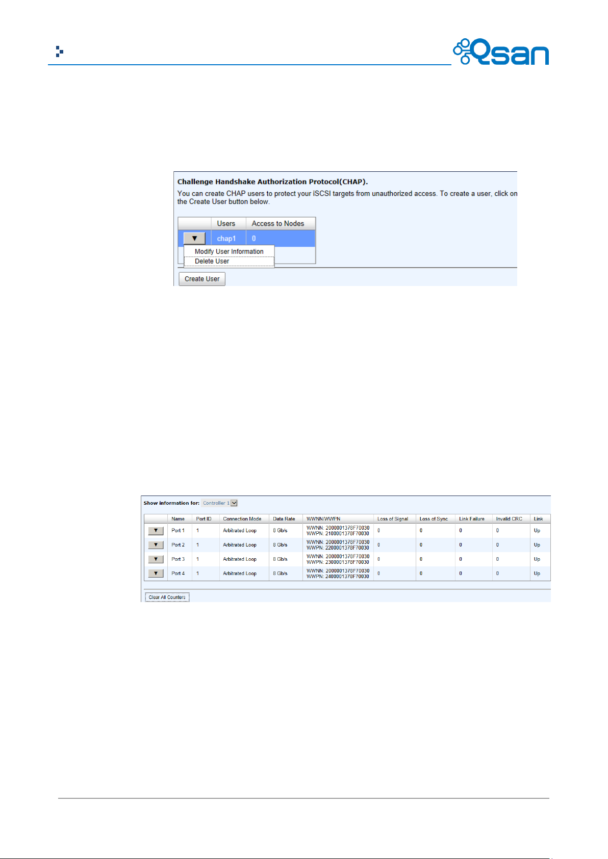
95
Copyright@2004~2014 Qsan Technology, Inc. All Rights Reserved.
Qsan Document – User Manual
。 Enter the required information for User Name, Secret, and Re-type Secret.
。 If you would like this CHAP user to have access, select one or multiple nodes. If
selecting none, you can add it later by iSCSI Configuration -> iSCSI Nodes -> Users.
。 Click OK button.
The options are available after creating a CHAP account:
▼ -> Modify User Information: Modify the selected CHAP user information.
▼ -> Delete User: Delete the selected CHAP user.
Fibre Channel
The Fibre Channel tab is used view the fibre channel information, and change the link speed of FC.
It displays the Port ID, Connection Mode, Data Rate, WWNN (World Wide Node Name), WWPN
(World Wide Port Name) , error count, and the link status.
The options are available on this tab:
Clear All Counters: Clear all counters of all fibre channels.
▼ -> Change Link Speed: There are Automatic / 2 Gb/s / 4 Gb/s / 8 Gb/s (for Q500-F20 /
Q500-F21 / F600Q), Automatic / 4 Gb/s / 8 Gb/s / 16 Gb/s (for Q500-F30 / V100-F30 /
F630Q) options. The default and recommended setting is to automatically detect the data
rate.
Page 96

96
Copyright@2004~2014 Qsan Technology, Inc. All Rights Reserved.
Qsan Document – User Manual
TIP:
Please be aware that there is no “Automatic” in Q500-F20 model. And Q500-F21
doesn’t support automatic link speed negotiation.
Attribute
Point-to-Point
Arbitrated Loop
Switched Fabric
Max ports
2
127
~16777216 (2^24)
Address size
N/A
8-bit ALPA
24-bit port ID
Side effect of port
Link fails
Loop fails (until port
N/A
▼ -> Change Connection Mode: There are Loop / Point-to-Point / Fabric options. For Q500-
F30 / V100-F30 / F630Q model, 16Gb link speed supports Point-to-Point mode only.
。 Point-to-Point (FC-P2P): Two devices are connected directly to each other. This is the
simplest topology, with limited connectivity.
。 Loop (Arbitrated Loop)(FC-AL): In this design, all devices are in a loop or ring, similar to
token ring networking. Adding or removing a device from the loop causes all activity
on the loop to be interrupted. The failure of one device causes a break in the ring.
Fibre Channel hubs exist to connect multiple devices together and may bypass failed
ports. A loop may also be made by cabling each port to the next in a ring.
。 Fabric (Switched Fabric)(FC-SW): All devices or loops of devices are connected to Fibre
Channel switches, similar conceptually to modern Ethernet implementations.
Advantages of this topology over FC-P2P or FC-AL include.
Page 97

97
Copyright@2004~2014 Qsan Technology, Inc. All Rights Reserved.
Qsan Document – User Manual
failure
bypassed)
Mixing different link
rates
No
No
Yes
Frame delivery
In order
In order
Not guaranteed
Access to medium
Dedicated
Arbitrated
Dedicated
CAUTION:
The connection mode Point-to-Point does not support multi-node.
(* Reference from http://en.wikipedia.org/wiki/Fibre_Channel)
▼ -> Node Configuration: Set the selected fibre channel for multi-nodes configuration.
Check the nodes which can be accessed by the host.
▼ -> Clear Counters: Clear the counters of the selected fibre channel.
Page 98

98
Copyright@2004~2014 Qsan Technology, Inc. All Rights Reserved.
Qsan Document – User Manual
Column Name
Description
Slot
The position of a hard drive. The button next to the number of slot shows
the functions which can be executed.
Size (GB) or (MB)
Capacity of hard drive. The unit can be displayed in GB or MB.
RAID Group
RAID group name.
RAID Set
The number of RAID Set:
N/A: The RAID group is traditional provisioning.
Number: The RAID group is the number of RAID set of thin
provisioning.
Virtual Disk
Virtual disk name for SSD caching.
Status
The status of the hard drive:
Online: The hard drive is online.
Rebuilding: The hard drive is being rebuilt.
Transitioning: The hard drive is being migrated or is replaced by
another disk when rebuilding occurs.
Scrubbing: The hard drive is being scrubbed.
Health
The health of the hard drive:
Good: The hard drive is good.
Failed: The hard drive is failed.
Error Alert: S.M.A.R.T. error alerts.
Read Errors: The hard drive has unrecoverable read errors.
Usage
The usage of the hard drive:
RAID: This hard drive has been set to a RAID group.
Free: This hard drive is free for use.
Dedicated Spare: This hard drive has been set as dedicated spare of a
RAID group.
Volume Configuration
The Volume configuration menu option is for accessing the Physical Disks, RAID Groups, Virtual
Disks, Snapshots, Logical Units, and QReplicas option tabs.
Physical Disks
The Physical Disks tab provides the status of the hard drives in the system. The two drop-down
lists at the top enable you to switch between the local system and any expansion JBOD systems
attached. The other is to change the drive size units (MB or GB).
This table shows the column descriptions.
Page 99

99
Copyright@2004~2014 Qsan Technology, Inc. All Rights Reserved.
Qsan Document – User Manual
Local Spare: This hard drive has been set as local spare of the
enclosure.
Global Spare: This hard drive has been set as global spare of whole
system.
Vendor
Hard drive vendor.
Serial Number
Hard drive serial number.
Rate
Hard drive rate:
SAS 6.0Gb/s.
SAS 3.0Gb/s.
SATA 6.0Gb/s.
SATA 3.0Gb/s.
SATA 1.5Gb/s.
SAS SSD 6.0Gb/s.
SATA SSD 6.0Gb/s.
Write Cache
Hard drive write cache is enabled or disabled. The default value is Enabled.
Standby
HDD auto spindown to save power. The default value is Disabled.
Read-Ahead
This feature makes data be loaded to disk’s buffer in advance for further
use. The default value is Enabled.
Command
Queuing
Newer SATA and most SCSI disks can queue multiple commands and
handle one by one. The default value is Enabled.
The options are available on this tab:
Disk Health Check: Check the health of the selected disks. It cannot check the disks which
are in used.
Disk Check Report: Download the disk check report. It’s available after executing Disk Health
Check.
▼ -> Set Free Disk: Make the selected hard drive be free for use.
▼ -> Set Global Spare: Set the selected hard drive to global spare of all RIAD groups.
▼ -> Set Local Spare: Set the selected hard drive to local spare of the RIAD groups which
located in the same enclosure.
▼ -> Set Dedicated Spare: Set a hard drive to dedicated spare of the selected RAID group.
▼ -> Upgrade: Upgrade the firmware of the hard drive.
▼ -> Disk Scrub: Scrub the hard drive. It’s not available when the hard drive is in used.
▼ -> Read Error Cleared: Clean the read error of the hard drive.
▼ -> Turn on/off the indication LED: Turn on the indication LED of the hard drive. Click
again to turn off.
▼ -> More information: Display hard drive detail information.
Page 100

100
Copyright@2004~2014 Qsan Technology, Inc. All Rights Reserved.
Qsan Document – User Manual
TIP:
In AegisSAN Q500 and AegisSAN LX, the maximum number of physical
drives in a system is 256.
Column Name
Description
Name
RAID group name.
Total (GB) or (MB)
Total capacity of the RAID group. The unit can be displayed in GB or MB.
Free Capacity
(GB) or (MB)
Free capacity of the RAID group. The unit can be displayed in GB or MB.
Available Size
(GB) or (MB)
Available capacity of the RAID group. The unit can be displayed in GB or
MB.
Thin Provisioning
The status of Thin provisioning:
Disabled.
Enabled.
Disks Uses
The number of physical disks in the RAID group.
Take an example to set the physical disk to dedicated spare disk.
1. Check ▼ -> Set Dedicated Spare at one physical disk.
2. If there is any RAID group which is in protected RAID level and can be set with dedicate spare
disk, select one RAID group, and then click OK button.
RAID Groups
The RAID Groups tab provides to create, modify, delete, or view the status of the RAID groups.
Use the drop-down list at the top to change the drive size units (MB or GB).
Select the traditional RAID group, it displays on the following.
This table shows the column descriptions.
 Loading...