

Page 1
Visualizer Software User Manual
Visualizer Software
User Manual
Version 3.00
QOMO Hite Vision
© Copyright 2012 QOMO HiteVision, LLC. All Rights Reserved 1
Page 2

Visualizer Software User Manual
Table of Contents
Title Page ............................................................................................................................ 1
Table of Contents ............................................................................................................... 2
Part 1 Overall Description of Software ............................................................................ 3
Installation of Software ............................................................................................................. 3
Full Installation ................................................................................................................ 3
Custom Installation ......................................................................................................... 7
Uninstall the Software ............................................................................................................. 11
Startup the Software ................................................................................................................ 14
Exit the Software ..................................................................................................................... 14
Introduction to the Software Interface .................................................................................... 14
Window Mode ............................................................................................................... 14
Full Screen Mode ......................................................................................................... 15
Part 2 Introduction to the Main Interface Function of the Software ........................... 16
Menu Bar ................................................................................................................................ 17
View Menu ..................................................................................................................... 18
Annotation Menu........................................................................................................... 19
Tool Menu ...................................................................................................................... 21
Visualizer Menu ...................................................................................................................... 23
Open ............................................................................................................................... 24
Setting ............................................................................................................................ 24
Device ............................................................................................................................ 25
Exit .................................................................................................................................. 25
Panel ........................................................................................................................................ 25
Picture Index Panel ...................................................................................................... 26
Picture Search Index Panel ........................................................................................ 26
Panel Locking/Hiding ................................................................................................... 27
© Copyright 2012 QOMO HiteVision, LLC. All Rights Reserved 2
Page 3
Visualizer Software User Manual
Part 1 Overall Description of Software
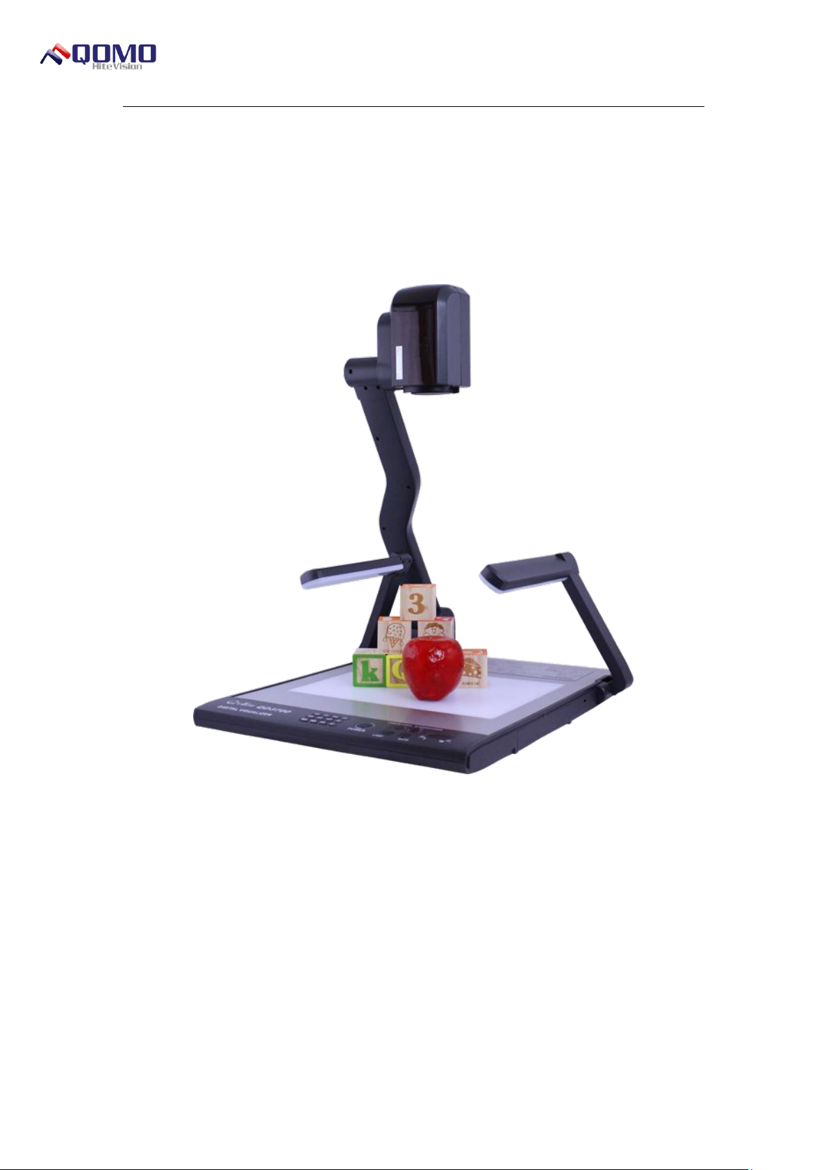
The QOMO Visualizer software is designed to provide extra features that may not be
included with a document camera. The software will assist the user during presentations,
lessons, and video conferencing. Users can capture and view the pictures, record, play
videos, and annotate over the image during a presentation.
Installation of Software
To install the software, double click the .exe program file. The software provides a Full
Installation mode and the Custom Installation mode, and users can select the installation
mode according to their own requirement. The following will explain the steps of the full
installation and the custom installation respectively.
Full Installation
The full installation procedure of the software is shown as follows:
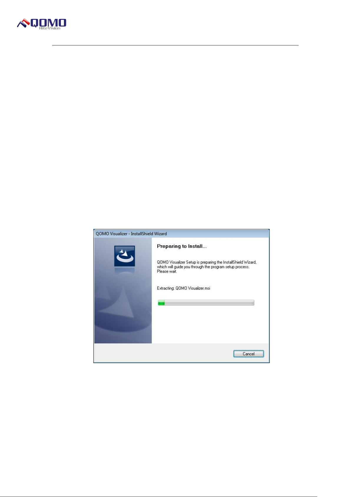
1. Double click the .exe installation program file in the software for the Installation
Interface is shown in Figure 1- 1 Preparation for Installation Interface.
Figure 1- 1 Preparation for Installation Interface
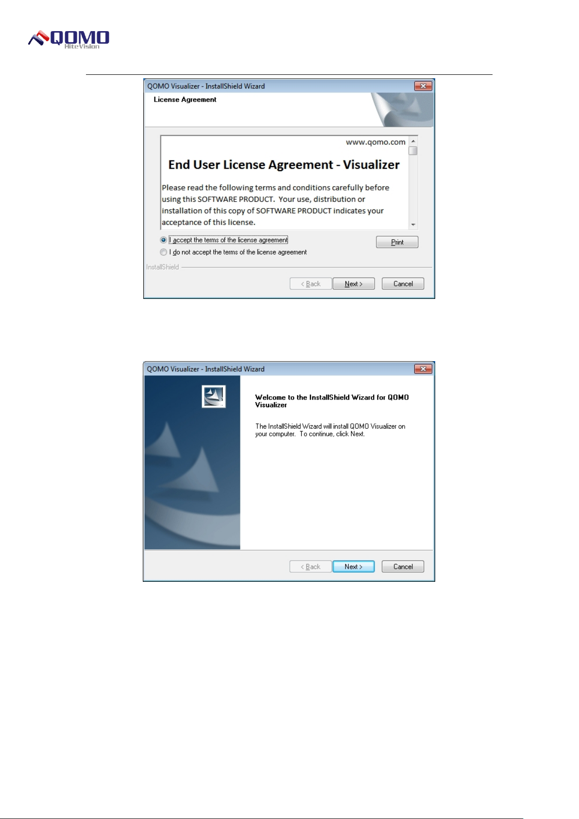
2. Click the “Next” button, to display the License Agreement interface as shown in
Figure 1- 2 License Agreement Interface. Go into the License Agreement interface, to
select the “I Agree to This Agreement” option to continue the installation.
© Copyright 2012 QOMO HiteVision, LLC. All Rights Reserved 3
Page 4
Visualizer Software User Manual
Figure 1- 2 License Agreement Interface
3. Click Next to complete the installation process as shown in Figure 1-3.
Figure 1- 3 Installation Wizard Interface
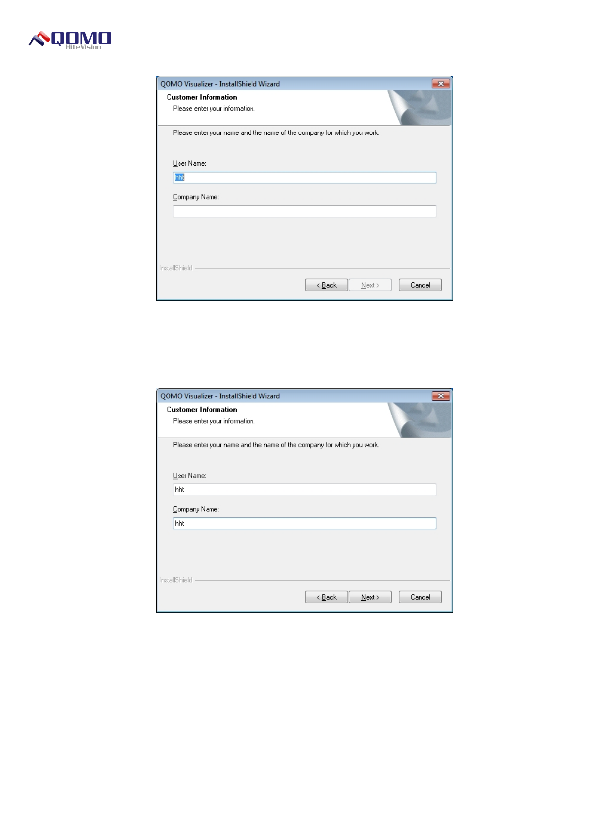
4. When you get to the Customer Information page, as shown in Figure 1-4, enter the
relevant information.
© Copyright 2012 QOMO HiteVision, LLC. All Rights Reserved 4
Page 5
Visualizer Software User Manual
Figure 1- 4 Customer Information Interface
It is necessary for users to input the company name in order to continue the process.
Click Next to continue, as shown in Figure 1- 5 After Input of the Customer Information.
Figure 1- 5 After Input of the Customer Information
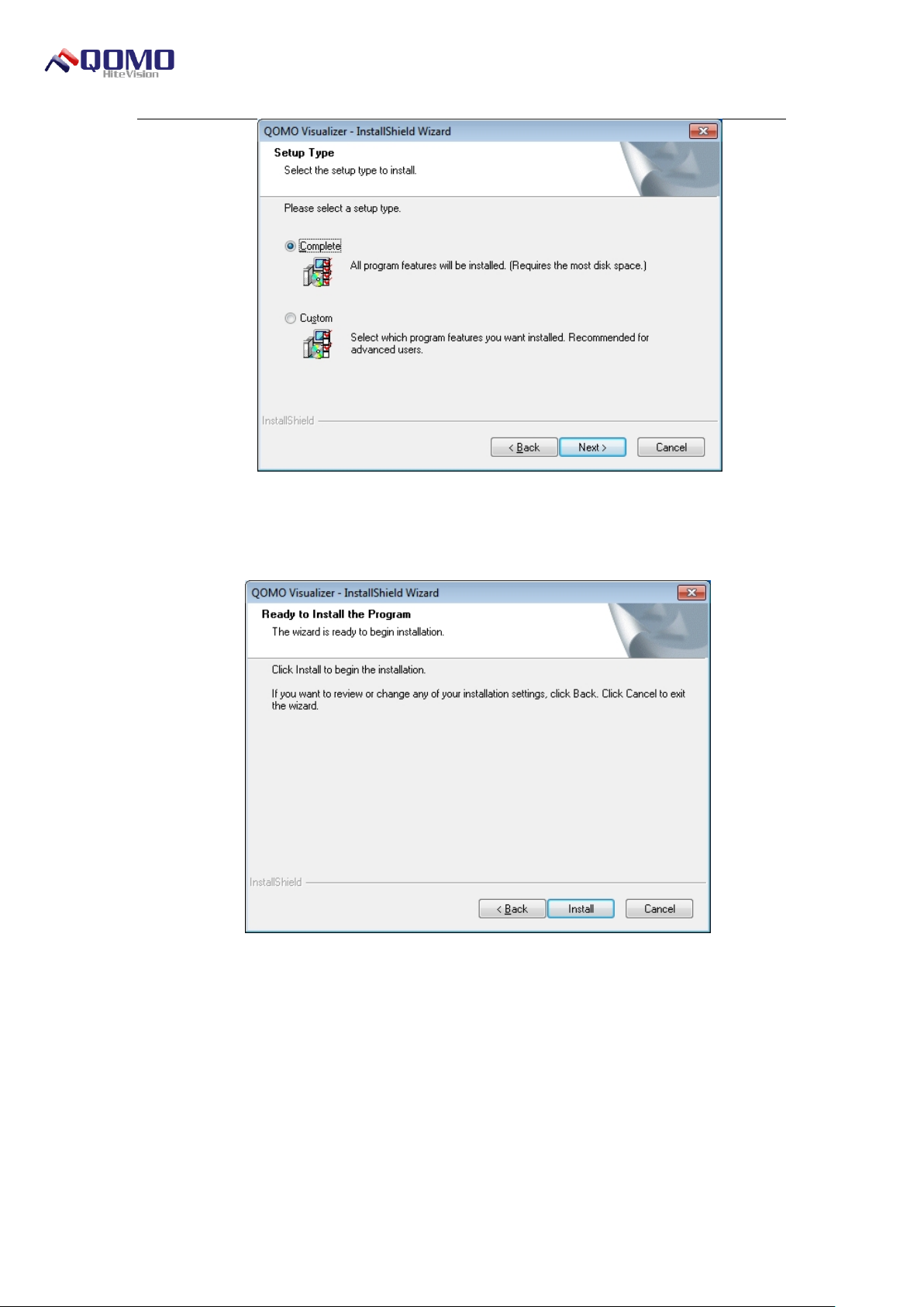
5. The setup type window allows users to customize the type of installation, as shown
in Figure 1- 6 Installation Type Interface. The default installation type is the full installation.
Select the type of installation and click Next.
© Copyright 2012 QOMO HiteVision, LLC. All Rights Reserved 5
Page 6
Visualizer Software User Manual
Figure 1- 6 Installation Type Interface
Figure 1- 7 Installation Confirmation Interface
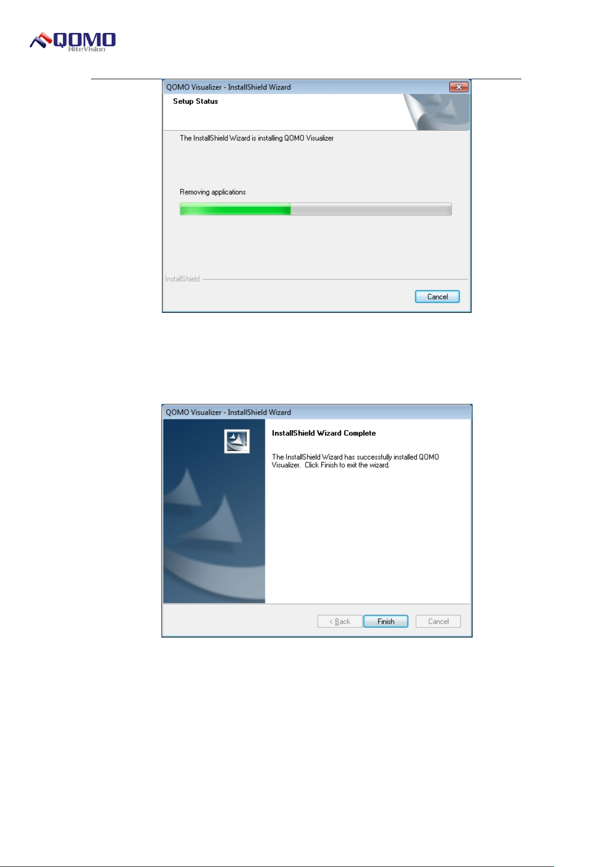
6. Click Install to finalize the installation process, as shown in Figure 1- 8 Installation
Status Interface. Users can view the installation progress.
© Copyright 2012 QOMO HiteVision, LLC. All Rights Reserved 6
Page 7
Visualizer Software User Manual
Figure 1- 8 Installation Status Interface
7. After the software is installed successfully, it will display the Completion of Software
Installation window as shown in Figure 1- 9 Completion of Software Installation.
Figure 1- 9 Completion of Software Installation
Custom Installation
The installation step for the custom installation of the software is similar to that of the
full installation.
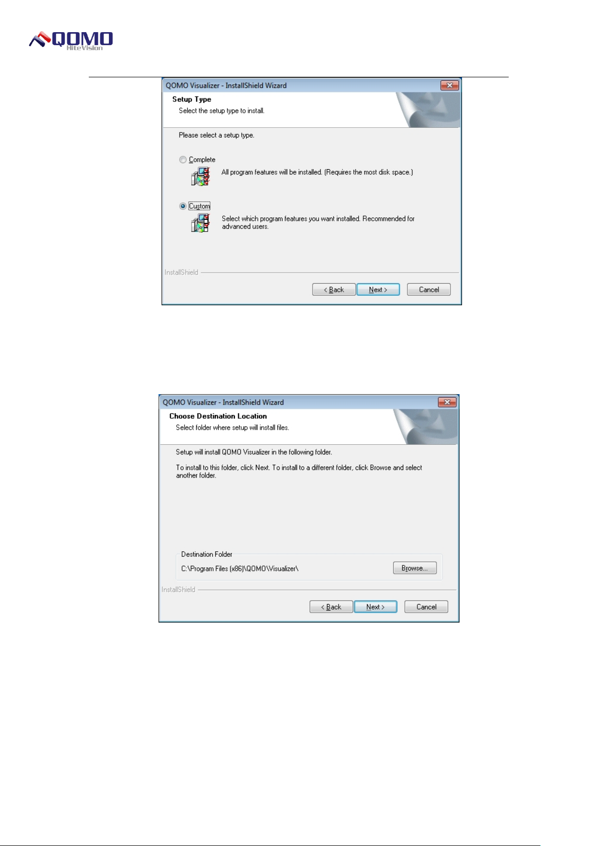
1. Select the custom installation type from the Installation Type interface as shown in
Figure 1- 10 Select Custom Installation
© Copyright 2012 QOMO HiteVision, LLC. All Rights Reserved 7
Page 8
Visualizer Software User Manual
Figure 1- 10 Select Custom Installation
2. Select the installation path as shown in Figure 1- 11 Select Installation Path Page,
and click Next.
Figure 1- 11 Select Installation Path Page
3. Click Browse to select the path for the destination folder, as shown in Figure 1- 12
Select Installation Path Dialog Box. Users can select the installation path of the software
according to their own requirement.
© Copyright 2012 QOMO HiteVision, LLC. All Rights Reserved 8
Page 9

Visualizer Software User Manual
Figure 1- 12 Select Installation Path Dialog Box
4. After the installation path is selected, click OK, The interface is shown in Figure 113 Installation Path Is Selected Interface.
Figure 1- 13 Installation Path Is Selected Interface
5. Click Next to enter the Select Function interface as shown in Figure 1- 14 Select
Features Interface.
© Copyright 2012 QOMO HiteVision, LLC. All Rights Reserved 9
Page 10

Visualizer Software User Manual
Figure 1- 14 Select Features Interface
6. Click Next to enter the Installation Confirmation page as shown in Figure 1- 15
Installation Confirmation Page.
Figure 1- 15 Installation Confirmation Page
7. Click Install to continue with the installation process as shown in Figure 1- 16
Installation Status Interface, Users can view the installation progress.
© Copyright 2012 QOMO HiteVision, LLC. All Rights Reserved 10
Page 11

Visualizer Software User Manual
Figure 1- 16 Installation Status Interface
8. After the software is installed successfully, a window will show that the software
was installed successfully, as shown in in Figure 1- 17 Completion of Software Installation.
Click Finish to complete the process.
Figure 1- 17 Completion of Software Installation
Uninstall the Software
There are two methods to uninstall the QOMO Visualizer software respectively:
© Copyright 2012 QOMO HiteVision, LLC. All Rights Reserved 11
Page 12

Visualizer Software User Manual
★ Go to the Start Menu, click on the program menu, and click on the QOMO
visualizer folder. Select the Uninstall option from the menu.
★ Go to the Control Panel, select the Programs and Features icon, then click
from the program list. Click the Uninstall button at the top of the
window.
The uninstallation steps of the software are shown as follows:
1. When users uninstall the software, the Preparation for Installation interface as
shown in Figure 1- 18 Preparation for Installation Interface will show.
Figure 1- 18 Preparation for Installation Interface
2. The Uninstallation Confirmation dialog box as shown in Figure 1- 19
Un-installation Confirmation Dialog Box, will prompt you to verify to remove the
software.
Figure 1- 19 Un-installation Confirmation Dialog Box
© Copyright 2012 QOMO HiteVision, LLC. All Rights Reserved 12
Page 13

Visualizer Software User Manual
3. Click Yes to finalize the uninstallation, as shown in Figure 1- 20 Installation Status
Interface.
Figure 1- 20 Installation Status Interface
4. After the software is uninstalled, it will display that the Software Was Uninstalled
Successfully as shown in Figure 1- 21 Completion of Software Uninstallation.
Click the Finish button to complete the uninstallation.
Figure 1- 21 Completion of Software Uninstallation
© Copyright 2012 QOMO HiteVision, LLC. All Rights Reserved 13
Page 14

Visualizer Software User Manual
Startup the Software
There are two methods to start the QOMO Visualizer software respectively:
★ Go to the Start menu, select the QOMO visualizer folder, then select QOMO
Visualizer.
★ Double click the Visualizer icon on the desktop.
Exit the Software
There are three methods to exit the QOMO Visualizer software respectively:
★ Click the button in the upper right corner of the window directly.
★ Click the button in the upper left corner of the software and select Exit from the
Visualizer menu.
★ Double click the button in the upper left corner of the software to close the
software directly.
Introduction to the Software Interface
The QOMO Visualizer software provides two application modes: window mode and
full screen mode. The following will describe the two modes:
Window Mode
The window mode is similar to the operating mode of a Windows program. The main
interface of the software is composed of the menu bar, panel, and preview area as shown
in Figure 1- 22 Window Mode.
© Copyright 2012 QOMO HiteVision, LLC. All Rights Reserved 14
Page 15

Visualizer Software User Manual
Menu Bar
Preview Area
Picture Index Panel and
Picture Search Index Panel
Figure 1- 22 Window Mode
Full Screen Mode
Users can switch to the full screen mode from the window mode in the following three
ways.
★ Select the View menu from the menu bar and click the Full Screen button in the
toolbar as shown in Figure 1- 23 Full Screen Mode.
★ In the window mode press the Esc key in the keyboard directly.
★ Double click the preview area when in the window mode.
© Copyright 2012 QOMO HiteVision, LLC. All Rights Reserved 15
Page 16

Visualizer Software User Manual
Click here to
switch mode
Figure 1- 23 Full Screen Mode
The preview area in the full screen mode covers the entire screen and it can display
the image and content clearly. The function is exactly consistent with the window mode.
The toolbar in the full screen mode can be moved and placed at any location. You cannot
exit the software in the full screen mode. It is necessary for you to switch to the window
mode first.
Users can exit the full screen mode in the following three ways.
★ Select the View menu from the menu bar and select the Screen option from the
toolbar.
★ Press the Esc key in the keyboard.
★ Double click the preview area.
Part 2 Introduction to the Main Interface
Function of the Software
The QOMO Visualizer software provides some common tools, such as zoom in/zoom
out, roam view, and rotate in the View menu. In the annotation menu, you can select an
object, draw a free line, highlight, and draw basic shapes. In the tools menu, you can
© Copyright 2012 QOMO HiteVision, LLC. All Rights Reserved 16
Page 17

Visualizer Software User Manual
Menu Bar
Picture Index Panel and
Picture Search Index Panel
Preview Area
capture an image, take continuous shots, copy, and record videos. This chapter mainly
introduces the functions and operating methods of various menus in the software.
The QOMO Visualizer software provides two application modes to meet the different
requirements of the users. The following examples, as shown in Figure 2-1, are shown in
the window mode of the software.
Figure 2- 1 Window Mode Main Interface
Menu Bar
The software provides users with the View, Annotation and Tool menus as shown in
Figure 2- 2 Menu Bar to provide users with the common function buttons of the software.
Users can switch among the various functions by clicking the different function menus.
Figure 2- 2 Menu Bar
© Copyright 2012 QOMO HiteVision, LLC. All Rights Reserved 17
Page 18

Visualizer Software User Manual
Button
Name
Function
Zoom In
Click this button to zoom in to the content displayed in the preview area. It may be
zoomed in up to 200%.
Zoom Out
Click this button to zoom out of the content displayed in the preview area. The
image cannot be zoomed out beyond 100%.
Zoom
In/Zoom
Out
Drop-down
Box
You can select proper magnification from the Zoom In/Zoom Out drop-down box.
The minimum magnification is 100% and the maximum magnification is 200%.
Roam view
Click this button and drag the mouse in the preview area to move all
images and objects in the preview area.
Clockwise
Rotation
Click this button once to rotate the image in the preview area 90° in the
clockwise direction.
View Menu
The View menu provides the common function buttons of the software as shown in
Figure 2- 3 View Menu. This menu provides the zoom in, zoom out, roam view, clockwise
rotation, counterclockwise rotation, and full screen function of the images in the preview
area.
Figure 2- 3 View Menu
The functions of the View menu are shown in Table 1.
© Copyright 2012 QOMO HiteVision, LLC. All Rights Reserved 18
Page 19

Visualizer Software User Manual
Counter-
clockwise
Rotation
Click this button once to rotate the image in the preview area for 90° in the
counterclockwise direction.
Full Screen
Click this button to display the image in the full screen mode in the
preview area. To exit the full screen, click the Full Screen button, double
click the mouse, or press the ESC button on the keyboard.
Button
Name
Function
Select object
Click this button to select an object in the preview area. Click this button
and drag the mouse around the object to select it as shown in Figure 2-5.
Figure 2- 5 Select Object
A selected object will have the following options appear at the corners of
Table 1 View Menu Function
Annotation Menu
The Annotation menu provides the common functions with annotating over images as
shown in Figure 2- 4 Annotation Menu. Functions include selecting objects, pencil drawing,
highlighting, drawing a line, ellipse, or rectangle; changing the pen color, pen style, or pen
width; and deleting an object or all objects.
Figure 2- 4 Annotation Menu
The functions of the Annotation menu are shown in Table 2.
© Copyright 2012 QOMO HiteVision, LLC. All Rights Reserved 19
Page 20

Visualizer Software User Manual
the selected area:
1. Place the mouse on the upper left corner and drag the
mouse to move the object.
2. Place the mouse on the upper right corner, and drag the
mouse to rotate the object.
3. Place the mouse on the lower right corner and drag the
mouse to zoom the object.
Free Line
Click this button then drag the mouse in the preview area to draw or write
in the preview area.
Highlighter
Click this button then drag the mouse in the preview area, to highlight over
something. Different colors can be selected for the highlighter.
Ordinary Line
Click this button then drag the mouse in the preview area to draw a line.
Ellipse
Click this button, and then drag the mouse in the preview area to draw an
ellipse.
Rectangle
Click this button then drag the mouse in the preview area, to draw the
rectangle.
Pen Color
Click this button open the Color Selection box as shown in Figure 2- 6
Color Selection Box. to set the pen color.
© Copyright 2012 QOMO HiteVision, LLC. All Rights Reserved 20
Page 21

Visualizer Software User Manual
Figure 2- 6 Color Selection Box
Pen Style
Click this button and users can set the pen style.
.
Pen Width
Click this button and users can set the pen width.
.
Delete Object
Delete the writing content or objects in current selected area.
Delete All
Objects
Delete the writing content or objects in the whole preview area.
Table 2 Introduction to the Function of Annotation Menu
Tool Menu
The Tool menu performs operations to the image in the software as shown in Figure
2- 7 Tool Menu. This menu includes the image capture, continuous shot, copy, video
recording function.
© Copyright 2012 QOMO HiteVision, LLC. All Rights Reserved 21
Page 22

Visualizer Software User Manual
Button Name
Function
Image Capture
Click this button to save the content in the preview area seen by users
(including the projection and annotation), and can display and open the
corresponding pictures in the picture index panel.
Begin
Continuous
Shot
Click this button to open the Continuous Shot dialog box as shown in
Figure 2- 9 Setting of Continuous Shot Dialog Box.
Figure 2- 9 Setting of Continuous Shot Dialog Box
Figure 2- 7 Tool Menu
When you enter the Tool menu, the End-Continuous Shot and Stop Recording
buttons are gray and cannot be operated until those functions have been started and vice
versa. When users begin the Continusous Shot function or Start Recording, these buttons
turn to gray and cannot be operated until the function has been stopped, as shown in
Figure 2- 8 Tool Menu.
Figure 2- 8 Tool Menu
The concrete function is shown in Table 3.
© Copyright 2012 QOMO HiteVision, LLC. All Rights Reserved 22
Page 23

Visualizer Software User Manual
Click the dots button to select the storage path of the pictures
and set the time interval of the shots in the drop-down box. Then click
to start the continuous shot function.
End
Continuous
Shot
Click this button to stop the continuous shot function.
Copy
Click this button to capture the image in the preview area and then paste it
to the specified external file directly (such as the word document and PPT
file).
1) Click the Copy button.
2) Draw a selection box and then release the mouse. This saves the
image to your computers clipboard.
3) Open the destination document to paste the picture.
Start Video
Recording
Click this button to start recording a video file.
Stop Video
Recording
Click this button to stop recording the video file. A Save As window will
appear and users can select the storage location and file name.
Table 3 Functional Introduction to Tool Menu
Visualizer Menu
The Visualizer menu provides users with the open, setting, device and exit option.
The Device option is hidden if there is only one connected device and is displayed if there
are more than one device connected, as shown in Figure 2- 10 Visualizer Menu.
© Copyright 2012 QOMO HiteVision, LLC. All Rights Reserved 23
Page 24

Visualizer Software User Manual
Figure 2- 10 Visualizer Menu
Open
To open a picture or a video, click Open in the Visualizer menu as shown in Figure 211 Open Dialog Box.The supported formats for images are .bmp, .jpeg and .jpg and.avi for
videos. When a picture is opened, it will launch Windows photo viewer automatically.
When a video is opened, it will launch Windows Media player automatically.
Figure 2- 11 Open Dialog Box
Setting
Click Setting in the Visualizer menu to open the Set Video dialog box as shown in
Figure 2- 12 Set Video Dialog Box. Users can set the screen resolution, color space,
brightness, and contrast ratio, or click Default button to restore the setting to the original
value.
© Copyright 2012 QOMO HiteVision, LLC. All Rights Reserved 24
Page 25

Device
Visualizer Software User Manual
Figure 2- 12 Set Video Dialog Box
Click Device in the Visualizer menu, to show the Device drop-down menu as shown
in Figure 2- 13 Device Drop-down Menu.
Note: It is only displayed when there are more than one connected devices and it
supports up to five devices.The current operating Device 0 is gray and cannot be operated.
The device, such as Device1, is operational and can be switched. Select it to switch to
Device 1.
Figure 2- 13 Device Drop-down Menu
Exit
Click Exit in the Visualizer menu to exit the software directly.
Panel
The software provides users with a picture index panel and the picture search index
panel as shown in Figure 2- 14 Picture Index Panel.
© Copyright 2012 QOMO HiteVision, LLC. All Rights Reserved 25
Page 26

Visualizer Software User Manual
Figure 2- 14 Picture Index Panel
Picture Index Panel
The Picture Index panel will display the saved pictures when users open the software
during the visualizer session and will clear the content in the Picture Index when you exit
the software. Users can open a picture quickly by double clicking the picture in the Picture
Index as shown in Figure 2-15.
Figure 2- 15 Picture Index
Picture Search Index Panel
The software provides additional resource images. They can be found in the Picture
Search Index Panel as shown in Figure 2-16.
© Copyright 2012 QOMO HiteVision, LLC. All Rights Reserved 26
Page 27

Visualizer Software User Manual
Figure 2- 16 Picture Search Index
There are two methods for users to add the resource into the preview area.
1. Select the picture resource in the Picture Search Index, drag it into the preview
area, then release the mouse.
2. Select the picture in the Picture Search Index, press the left mouse key in the
preview area, and drag the mouse toward the lower right side. This will add the object
as a custom sized object.
Panel Locking/Hiding
The panel automatically hides when the cursor is moved away from it. To lock the
panel in place, click on the Pin button. To hide the panel again, click the Locked Pin
button.
© Copyright 2012 QOMO HiteVision, LLC. All Rights Reserved 27
Page 28

Visualizer Software User Manual
Figure 2- 17 Before Panel Locking
Click the button in the figure above. The panel is locked as shown in Figure 2- 18
After Panel Locking.
Figure 2- 18 After Panel Locking
When the panel is locked, the panel can be dragged and placed to any location of the
screen.
.
© Copyright 2012 QOMO HiteVision, LLC. All Rights Reserved 28
Page 29

Visualizer Software User Manual
Figure 2- 19 Panel Movement
When the panel is moved, it will display different directional scrolling buttons in the
preview area as shown in Figure 2- 20 Panel Movement.
Figure 2- 20 Panel Movement
Move the panel to the corresponding directional buttons, such as to dock the panel to
the location as shown in Figure 2- 21 Move Panel Above Preview Area. The docking
method of other directions is the same as it.
© Copyright 2012 QOMO HiteVision, LLC. All Rights Reserved 29
Page 30

Visualizer Software User Manual
Figure 2- 21 Move Panel Above Preview Area
For additional information or resources regarding your QOMO product please go to
www.qomo.com.
Contact Information:
QOMO Hite Vision
46950 Magellan Drive
Wixom, MI 48393, USA
1-866-990-QOMO (7666)
1-248-960-0995
Email: support@qomo.com
© Copyright 2012 QOMO HiteVision, LLC. All Rights Reserved 30
 Loading...