

Page 1

Visual Presenter
Quick Start-up Guide
Model: QD700
Page 2
Turn off all power while setting up and making connections.
SETTING UP THE UNIT
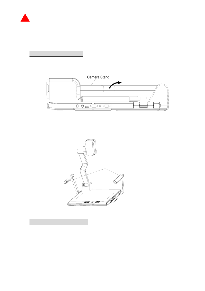
1. Use one hand holds the base of the visualizer, use the other
hand carefully lift up the camera stand of the unit.
2. Open the arm lights and rotate the camera head until they are in
proper positions.
Arm lights
MAKING CONNECTIONS
Before making any connection, turn off all the power, including
power of the visualizer and the equipment to be connected.
Step 1: Connect power source.
First connect the power cord to the 12V IN connector.
Page 3

Step 2: Connect to the projector.
Rear Panel
OUT
AUDIO VIDEO
OUT
S-VIDEO
IN
AUDIO VIDEO
AUDIO
IN
S-VIDEO
AUDIO IN
PROJECTOR
OUT -COMPUTER- IN
RGB Input
RS232 Cable
OUT-12V- IN
Screen
Projector
Side Panel
PROJECTOR
MIC
USB
RGB IN AUDIO IN
RS232
Connect visualizer’s PROJECTOR port to the RGB IN port of the
projector port with the RGB cable provided together the visualizer.
If you need control a projector with the visualizer, please use the
projector RS232 cable (6-pin to 9-pin) to make the connection
between the projector and the visualizer. Some projector models may
require a converter cable in addition to this standard RS232 cable to
connect to the projector control port, for the pin locations and shape
of some projectors’ control port connector may be different from the
connector of a standard RS232 cable. After the visualizer is
connected to the projector, you can control projector’s power on,
standby and input selection with the visualizer. (For projectors other
than Hitachi, the Code Writing program that comes with the visualizer
is required for this function.)
Step 3: Connect to a desktop computer.
Page 4

Rear Panel
OUT
AUDIO VIDEO
OUT
IN
IN
S-VIDEO
VIDEO AUDIO S-VIDEO
AUDIO
PROJECTOR OUT -COMPUTER- IN OUT-12V- IN
AUDIO IN
To the
Monitor
RGB Output
Computer
USB Connector
RS232
Cable
PROJECTOR
MIC
USB
RGB IN AUDIO IN
RS232
Side Panel
Note: You can connect a laptop computer to the RGB IN port of side
panel with a RGB cable.
Step 4: Connect to the first video equipment with S-Video input.
S-Video Cable
S-Video out
Video equipment
Projector
(or amplifier/speaker equipment)
Audio input
Audio out
Rear Panel
IN
IN
OUTOUT
AUDIO
VIDEO
S-VIDEO
AUDIO
S-VIDEO
VIDEO
AUDIO
AUDIO IN
PROJECTOR
OUT -COMPUTER- IN
OUT-12V- IN
Output of the S-Video signal from the visualizer to the projector is
already done in the step 2, where the RGB cable comes out from the
visualizer and goes to the projector . After the connections as steps 2,
3, 4 are made, input signals from the computer、visualizer CCD and
S-Video are going to the RGB1 input on the projector and will be
displayed on the projector screen as RGB1. These signals can be
seen in turn when pressing “CCD/PC1/PC2” and “S-VIDEO/VIDEO”
on the control panel of the visualizer.
Page 5

Remarks: RGB IN signal can not go to S-VIDEO OUT or VIDEO
OUT port to be displayed on the screen.
Step 5: Connect to the second video equipment with video input.
Video Cable
Video out
Video equipment
Audio out
Projector Color monitor
Video in
Rear Panel
OUTOUT
AUDIO
IN IN
VIDEO
S-VIDEO
AUDIO
S-VIDEO
VIDEO
AUDIO
AUDIO IN
PROJECTOR
OUT -COMPUTER- IN
OUT-12V- IN
Step 6: Connections for external control from the computer.
Side Panel
PROJECTOR
MIC
USB
RGB IN AUDIO IN
RS232
USB cable
USB connector
of the computer
RS-232 cable
RS 232 connector
of the computer
Use the computer RS232 cable (9-pin to 9-pin) to make the
connections shown below to control the visualizer from an external
computer.
USB connection enables capturing still images / video streams from
the visualizer to the computer. Special software is required for this
operation.
4. Turn on the power by pressing the “POWER” button.
Page 6

QOMO HITEVISION, LLC
Toll Free: 1-866-990QOMO
E-Mail: info@qomo.com
Web:
www.qomo.com
 Loading...