

Page 1

PRECAUTIONS
Please follow these precautions:
To prevent fire or shock hazard, do not expose the unit to rain or
moisture.
To prevent electrical shock, do not open the cabinet. Refer to qualified
personnel for service only.
Do not use the unit continuously for more than 24 hours with camera
auto focus on. It may cause damage to the camera lens.
Be careful not to spill water or other liquids onto the unit, or allow
combustible or metallic objects to get inside the cabinet.
Unplug the visualizer from the wall outlet when it is not being
used for a long period of time.
Clean the cabinet with a soft cloth lightly moistened with a mild
detergent solution.
Clean the lens carefully with an air spray or soft dry cloth to avoid
scratching it.
When the lamps flash or become dark, they should be replaced with
new ones.
Avoid switching arm lights and back light frequently.
Remove the camera lens cap before power the unit on.
CONTACTS:
QOMO Hitevision, LLC
Toll Free: 1-866-990QOMO
E-Mail: info@qomo.com
Web:
www.qomo.com
1
Page 2

CONTENTS:
PARTS IDENTIFICATION ..................................................................... 3
CONTROL PANEL ................................................................................ 3
BUTTON INSTRUCTION ...................................................................... 4
REMOTE CONTROL ............................................................................ 5
CONNECTIONS.................................................................................... 6
BASIC PREPARATIONS....................................................................... 6
OUTPUT MODE AND VERTICAL FREQUENCY (60Hz) ...................... 9
PAL/NTSC VIDEO OUTPUTS............................................................... 9
INSTALLING VISUALIZER SOFTWARE............................................... 9
USB CAPTURE FOR MAC COMPUTER.............................................11
WORKING ON THE STAGE ................................................................11
WORKING OUTSIDE THE STAGE......................................................11
LIGHT...................................................................................................11
ADJUSTING IMAGE SIZE .................................................................. 12
WORKING WITH NEGATIVES ........................................................... 12
FOCUSING ......................................................................................... 12
FREEZING IMAGE ............................................................................. 13
BRIGHTNESS ADJUSTMENT ............................................................ 13
WHITE BALANCE ADJUSTMENT ...................................................... 13
AUTO ADJUSTMENT ......................................................................... 13
TEXT/IMAGE MODE........................................................................... 13
COLOR AND B&W MODE SWITCH ................................................... 14
SWITCHABLE INPUTS....................................................................... 14
VISUALIZER ON/STANDBY ............................................................... 14
IMAGE REVERSION........................................................................... 14
IMAGE SPLIT...................................................................................... 14
DYNAMIC/STATIC MODE SWITCH.................................................... 15
TITLE FUNCTION............................................................................... 15
INFRARED REMOTE CONTROL ....................................................... 15
VOLUME ADJUSTMENT .................................................................... 15
USB PORT.......................................................................................... 15
VIDEO DISPLAY AND CAPTURE....................................................... 16
CONTROLLING THE VISUALIZER FROM A COMPUTER ................ 17
2
Page 3
FOLDING THE UNIT........................................................................... 18
SPECIFICATIONS............................................................................... 19
TECHNICAL SUPPORT...................................................................... 21
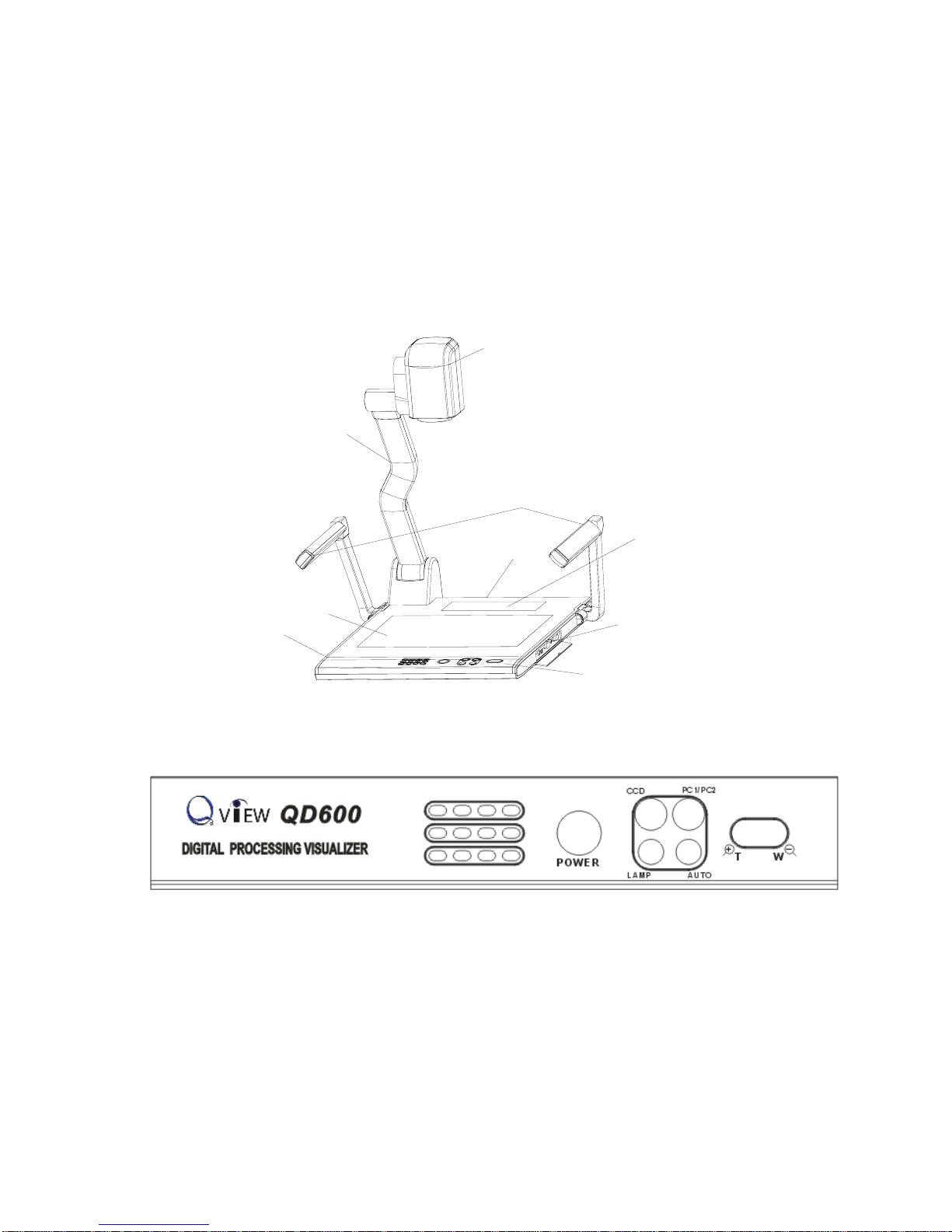
PARTS IDENTIFICATION
Arm lights
Camera
Camera stand
Back light
Remote control slot
Operation panel
Stage
Connectors
Connectors
Button instruction
CONTROL PANEL
POWER (Control the visualizer On/Off)
Mir (V-reverse the image)
Frz (Freeze the image)
Neg (Display film negatives)
Title (Freeze the top 1/8 of the screen)
D./S. (Switch between static mode and dynamic mode)
Far/Near (Focus far or near)
B+/B- (Adjust the brightness)
3
Page 4
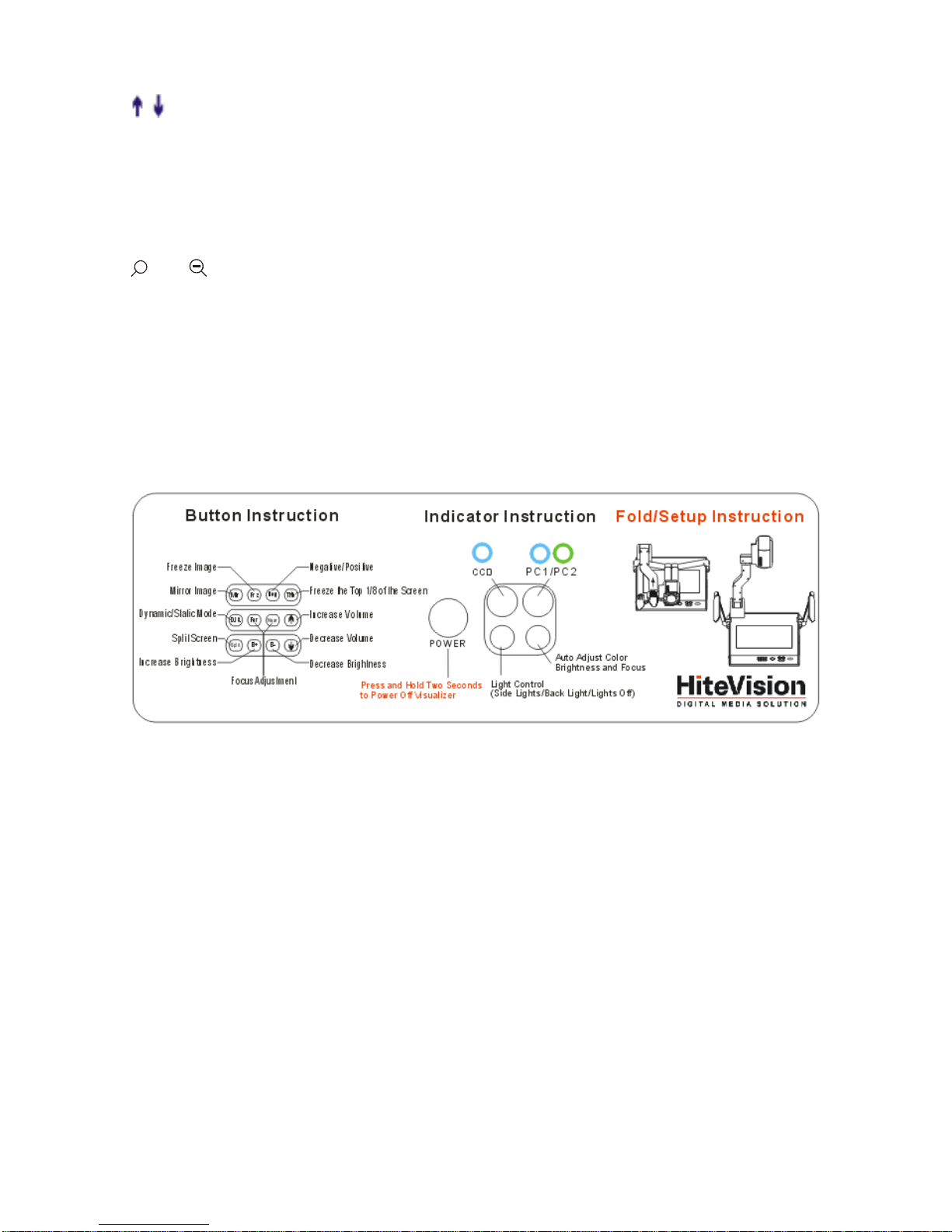
Split (Image Split function)
/ (Increase and decrease the volume)
CCD (Select to output CCD signal)
PC1/PC2 (Select to output computer1/computer 2 signal)
LAMP (Control the arm lights and back light)
AUTO (To auto adjust white balance and auto focus)
+
T/
W
(Increase and decrease the magnification)
Remarks: Frz, Title, D./S. and Split functions are only available on
PROJECTOR OUT port.
BUTTON INSTRUCTION
Button function instruction sheet
4
Page 5
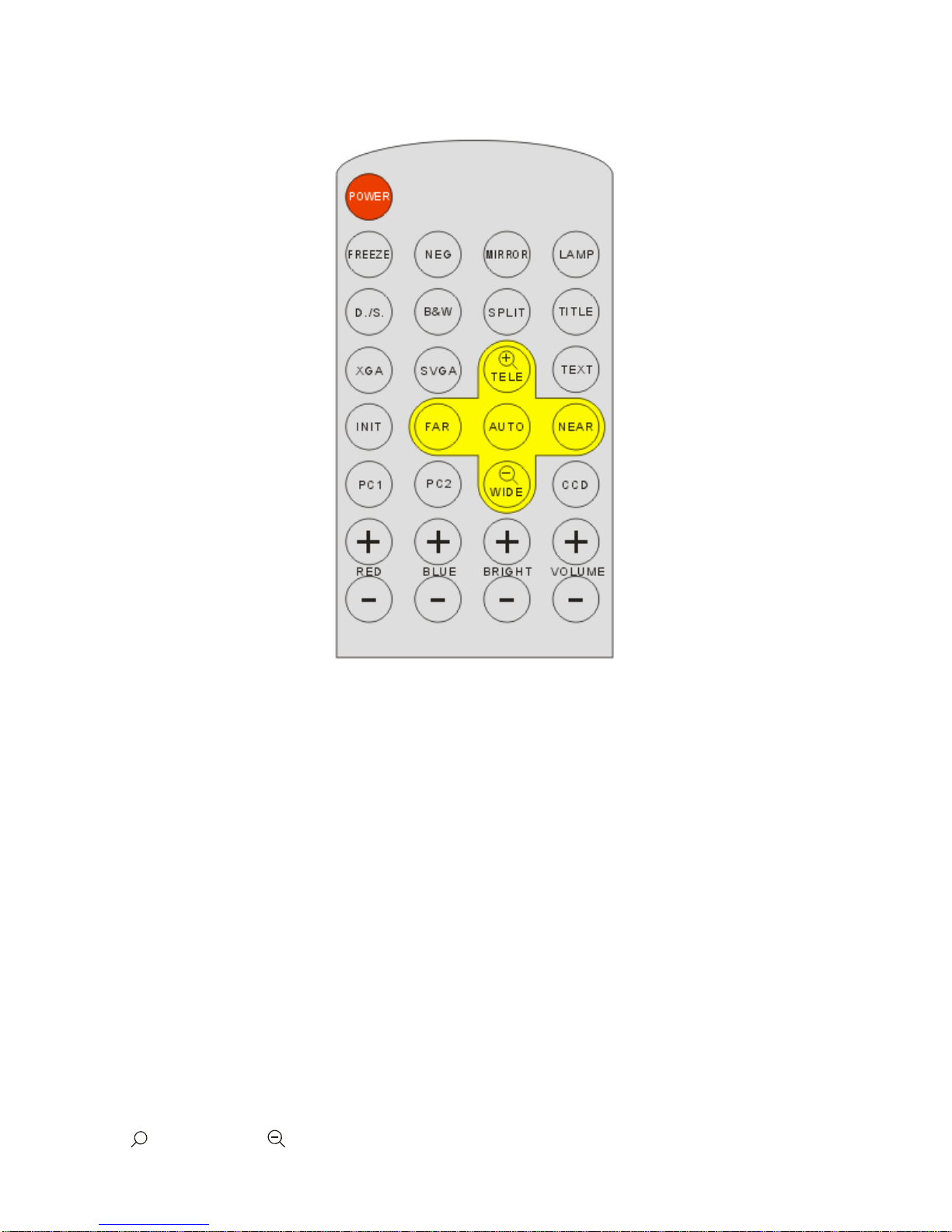
REMOTE CONTROL
POWER (Control the visualizer On/Off)
FREEZE (Freeze the image)
NEG (Display film negatives)
MIRROR
(V-Reverse the image)
LAMP (Control the arm lights and back light)
D./S. (
Switch between static mode and dynamic mode)
B&W (Switch between color mode and B&W mode)
SPLIT (Image split function)
TITLE (Freeze the top 1/8 of the screen)
XGA
(Set output signal resolution as XGA (1024 x 768) mode)
SVGA
(Set output signal resolution as SVGA (800 x 600) mode)
INIT (Restore to CCD default setting)
TEXT (Switch between image/text mode)
AUTO (To auto white balance and auto focus)
+
TELE/ IDEW (Increase and decrease the magnification)
5
Page 6
FAR/NEAR (Focus near or far)
CCD (Select to output CCD signal)
PC1 (Select to output computer 1 signal)
PC2 (Select to output computer 2 signal)
RED +/- (Increase/decrease the red hue)
BLUE +/- (Increase/decrease the blue hue)
BRIGHT +/- (Increase/decrease the brightness)
VOLUME+/- (Increase or decrease the volume)
Remarks: FREEZE, TITLE, D./S. and SPLIT functions are only
available on PROJECTOR OUT port.
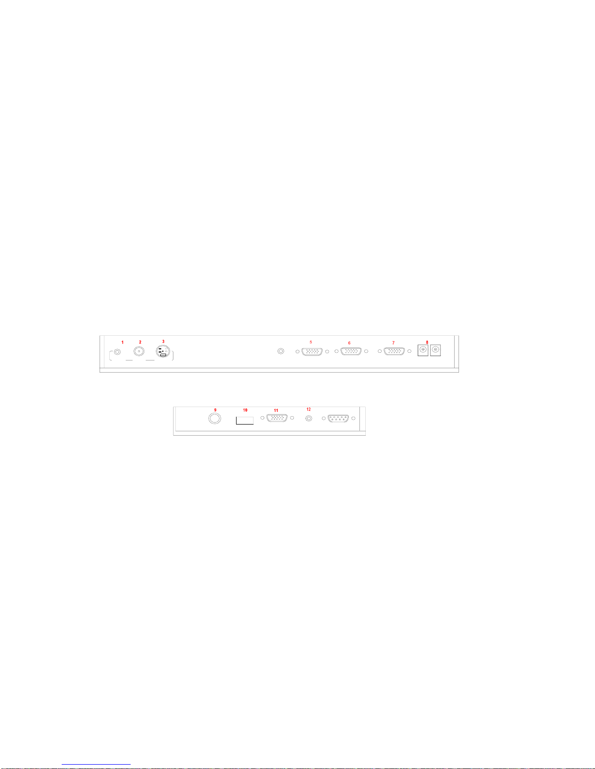
CONNECTIONS
#1 AUDIO OUT #2 VIDEO OUT #3 S-VIDEO OUT
#4 PC AUDIO IN #5 PROJECTOR Connector
#6 COMPUTER OUT #7 COMPUTER IN #8 POWER OUT/IN
#9 MIC IN #10 USB Connector #11 RGB IN
AUDIO IN
#12 RGB AUDIO IN #13 COMPUTER RS-232 Connector
BASIC PREPARATIONS
1. Use one hand holds the base of the visualizer, use the other hand
carefully lift up the camera stand of the unit.
4
Side Panel
Rear Panel
RGB IN
AUDIO
OUT
S-VIDEOVIDEO
USB
MIC
OUT
OUT-12V- IN OUT -C O M PUT E R - IN PROJECTOR
AUDIO IN
RS232
13
6
Page 7
2. Open the arm lights and rotate the camera head until they are in
proper positions.
Arm lights
3. Making connections:
Before making any connection, turn off all the power, including power of
the visualizer and the equipment to be connected.
Step 1: Connect power source.
First connect the power cord to the 12V IN connector.
Step 2: Connect to the projector.
7
Page 8

Connect visualizer’s PROJECTOR port to the RGB IN port of the
projector port with the RGB cable provided together the visualizer.
Projector
RGB Input
Screen
AUDIO IN
Rear Panel
AUDIO
OUT
S-VIDEO
OUT
VIDEO OUT-12V- IN OUT -COMPUTER- IN PROJECTOR
Step 3: Connect to a desktop computer.
Note: You can connect a laptop computer to the RGB IN port of side
panel with a RGB cable.
Step 4: Connections for external control from the computer.
RGB Output
To the
Monitor
USB Connector
Computer
RS232
Cable
Side Panel
MIC
PROJECTOR
USB
RGB IN AUDIO IN
RS232
Rear Panel
VIDEO AUDIO
OUT
S-VIDEO
OUT
OUT -COMPUTER- IN PROJECTOR
AUDIO IN
OUT-12V- IN
8
Page 9

RS 232 connector
USB connector
of the computer
of the computer
USB cable
RS-232 cable
Side Panel
USBMIC
RGB IN AUDIO IN
RS232
Use the computer RS232 cable (9-pin to 9-pin) to make the
connections shown below to control the visualizer from an external
computer.
USB connection enables capturing still images / video streams from
the visualizer to the computer. Special software is required for this
operation.
4. Turn on the power by pressing the “POWER” button.
OUTPUT MODE AND VERTICAL FREQUENCY (60Hz)
The RGB output can output a signal in the SVGA /XGA format.
In order to achieve the best picture quality you must set the outputs of
the visualizer to match the native resolution of your display unit.
PAL/NTSC VIDEO OUTPUTS
The S-Video and composite video outputs are set to PAL (NTSC) during
manufacturing.
INSTALLING VISUALIZER SOFTWARE
9
This function is to snap and display images with the USB interface,
which includes displaying static and dynamic pictures, snapping
dynamic images and playback the dynamic images with the Windows
Page 10

Media Player or its own player.
A. Insert the CD-ROM that comes with your visualizer into the
CD-ROM drive.
B. Click the Code-Writing folder to install Code-Writing Program.
C. Click the DirectX9.0 folder to install Microsoft DirectX 9.0.
D. Click the Capture Program folder to install the program that
captures images in the AVI or JPG format.
E. Shut down your computer when prompted so the changes will take
effect.
F. Use the USB cable to connect your computer to the visualizer
before your computer is restarted.
G. Turn on the visualizer.
Remarks: DirectX9.0 is not necessary to install, it is mainly for computer
print screen function.
Please pay attention to the following:
1. Computer hardware requirement: CPU: Pentium 4, RAM: 256M or
above, USB 2.0 port, Hard disk 40G or more
2. Operating system: Windows 2000 or above. If the operating system
is Windows 2000, should install SP4. If the operating system is
Windows XP, should install SP1.
3. Must use the high-speed USB cable provided together with the
visualizer.
4. When connect the visualizer to a desktop computer with the
high-speed USB cable provided together with visualizer, we
recommend using the USB port on the rear of the mainframe as the
USB port on the front of the computer might have interference.
5. You need to install the USB driver again when you change a
computer’s USB port. If this port has installed USB2.0 driver, then no
need to install USB driver again.
6. When you open capture program, but can not capture the image,
please set the signal input source: click “Option”Æ“Video Crossbar”, and
then set INPUT as Video Composite In.
10
Page 11

USB CAPTURE FOR MAC COMPUTER
Copy the folder “Mac Driver” into Mac hard disk, open the folder and
double-click Empia 1.0.0b2.zip, the “setup” file appears. Follow
dialog-box messages, click “next” and finish installation.
Note:
1. Please connect Mac computer and visualizer when installing
2. Please use USB2.0 from visualizer accessories.
WORKING ON THE STAGE
1. Place your material on the working surface.
2. Select the enlargement required with the “
+
T” and “
W
” keys.
3. Adjust the focus with the “Near” and “Far” keys or “AUTO” key.
WORKING OUTSIDE THE STAGE
For showing 3-dimensional objects with the visualizer, just place them
on the working surface and adjust the “
+
T” or “
W
” and “AUTO” keys. If
the object is too big for the stage or you want to show it from the side,
just place it behind or in front of the unit and tilt the camera by hand
(please take off the close-up lens first).
Rotate 330 degrees
vertically
LIGHT
The arm lights are on when the power is on. Each time you press the
“LAMP” buttons, the lighting changes as below.
11
Page 12

The arm lights turn on
The back light turns on
All the lights turn off
ADJUSTING IMAGE SIZE
In order to reduce or enlarge the image size displayed on the screen,
press the “
+
T” or “
W
” button.
WORKING WITH NEGATIVES
The visualizer is automatically set to display normal materials on the
screen when the power is on. To display negatives, turn on the backlight
by pressing the “LAMP” key, and then press the “Neg” button to display
the film negatives. Press the “Neg” button again to display normal
materials in the color mode.
FOCUSING
When the Visualizer is turned on the focus automatically adjusts to the
12
Page 13

stage, it is not necessary to readjust the focus if you are only working
with flat materials (text, photos, etc.). Only 3D objects require a focus
adjustment.
Press the “AUTO” button to auto focus.
Press the “FAR” or “NEAR” button once to focus manually.
FREEZING IMAGE
Press the “Frz” button to freeze the image. When the output signal is
RGB, in order to show a still image on the screen, press the “Frz” button.
The frozen image can’t be adjusted (Zoom in/out, color adjustment,
etc.).
Note: This function is not available on S-Video and Video
output.
BRIGHTNESS ADJUSTMENT
If the image effect is not satisfactory, you can adjust the brightness to get
a better image effect. Use the “BRIGHT +” or “BRIGHT -” button to
adjust the brightness. To increase the brightness, press the “BRIGHT +”
button. To decrease it, press the “BRIGHT -” button. To go back to the
initial brightness press the “AUTO” button.
WHITE BALANCE ADJUSTMENT
Each time the lighting condition changes, the user should adjust the
white balance of the CCD.
Press the “AUTO” button to adjust the white balance automatically.
AUTO ADJUSTMENT
One of the QD600’s special functions is auto adjustment. Press the
“AUTO” button to auto adjust the white balance and the focus. The
whole process takes about 10 seconds.
TEXT/IMAGE MODE
Press the “TEXT” button to switch between image/text modes. To
display a text file, switch to the text mode to get a clearer text effect.
13
Page 14

(On the remote control)
COLOR AND B&W MODE SWITCH
Press “B&W” once to enter the Black & White mode; Press again to
return to the Color mode.
SWITCHABLE INPUTS
Use the “CCD” button to output CCD signal, use the “PC1/PC2” button
to output computer 1 or computer 2 signal.
Each time the “PC1/PC2” button is pressed, it provides seamless
transitions among different sources such as computer 1 and computer 2.
Notes: RGB OUT always outputs RGB IN signals.
VISUALIZER ON/STANDBY
Press the “POWER” button to turn on the visualizer’s power. To turn the
visualizer standby after use, press the “POWER” button more than 2
seconds.
IMAGE REVERSION
Press the “Mir” button once to V-reverse the image and the vertically
mirrored image will be displayed. Press the “Mir” button again to exit.
(On the remote control, please press the “MIRROR” button)
IMAGE SPLIT
Press “SPLIT”, the image will be split into two images. One is the current
captured image the other is a frozen image of the last image, Press the
“SPLIT” button again to exit.
14
Page 15

Note: This function is not available on S-Video and Video
output.
DYNAMIC/STATIC MODE SWITCH
To display dynamic images, Press the “D./S.” button to switch to
the Dynamic mode, the image will be clear and has no choppy strobe
effect. To display still images, press the “D. / S.” button switch to the
Static mode.
Note: This function is not available on S-Video and Video
output.
TITLE FUNCTION
Press the “Title” button once, the image split into two parts, the upper 1/8
part of the image will freeze and stay on top 1/8 of the screen. Press
“Title” button again to exit the Title mode.
Note: This function is not available on S-Video and Video output.
INFRARED REMOTE CONTROL
The QD600’s remote control can control the camera from different
angels. Please note that an infrared remote control can only be used up
to a certain distance to the unit. Objects situated between the visualizer
and the infrared remote control and a weak battery may interfere with
the reception.
On the left side of the visualizer stage, there is a built-in remote control
storage compartment where you can store the remote control when you
not use it.
VOLUME ADJUSTMENT
Press the “ ” button to increase the volume; Press the “ ” button to
decrease the volume.
USB PORT
The USB port can be used to transfer still images from the visualizer to a
computer. No additional computer hardware is required. In this way, the
15
Page 16

visualizer can be used as a 3-D scanner for your computer.
Connect the Visualizer to your computer with the supplied USB cable.
The Visualizer Software is available on the supplied CD-ROM.
VIDEO DISPLAY AND CAPTURE
A. Static Images Snap
Select [Start] -> [All Programs] -> [VideoCap] –> “VideoCap” to open the
VideoCap.exe. Click [File] -> [Set Capture File] to locate the image file
into your desired folder. Then click [Set Frame File Name] to input the
name of the file. Click [Capture] -> [Capture Frame] to save the static
image.
B. Snap Video Stream
Click [File] -> [Set Capture File] to select the location of the file to be
saved. Then input the name of the file. Click [Capture] -> [Start Capture]
to start capture, and click [Capture] -> [Stop Capture] to stop. If you want
to set the time limit for the capture, select [Capture] -> [set time limit] to
set the time limit. (If you have set the time limit, it will stop automatically
when the time is up.)
C. Display and Edit the Static Image
You can use the “Imaging” or “Paint” tool to display and edit the static
image. To run a tool, click [Start] -> [All Program] -> [Accessories] ->
“Imaging” or “Paint” to open a picture. A sample is shown as follows:
D. Play Video Stream
Click [Start] -> [All Programs] -> [Accessories] -> [Entertainment] –>
16
Page 17

“Windows Media Player” or “ActiveMovie control”. You can also click
[File] -> [Display Captured Video Stream] to play video stream in the
VideoCap program.
E. Set the Frame Rate
Click [Capture] -> [Set Frame Rate], and click open “Choose Frame
Rate” to set the frame rate.
F. Set Time Limit
Click [Capture] -> [Set Time Limit] to set the time limit while capturing
video.
G. Control the CCD
Click [Option] -> [Video Capture Filter] -> [Video Proc Amp], open the
dialog to adjust “Brightness”, “Contrast”, etc. Use “Default” to set each
parameter to the default.
H. Note:
Don’t connect / disconnect the USB cable when the application is
running, it will cause the program to be interrupted.
CONTROLLING THE VISUALIZER FROM A COMPUTER
You can control the Visualizer from a computer connected with a RS232
connector.
A. Connect the computer and the visualizer with the computer RS-232
cable (9-pin to 9-pin).
B. Select [Start] -> [Program] -> [VideoCAP] -> “VideoCAP” to open
the VideoCap.exe.
C. Click “Visualizer Control” under “Capture”.
D. Select the COM port COM1 or COM2,and you can control the
visualizer by clicking the buttons on the menu.
17
Page 18

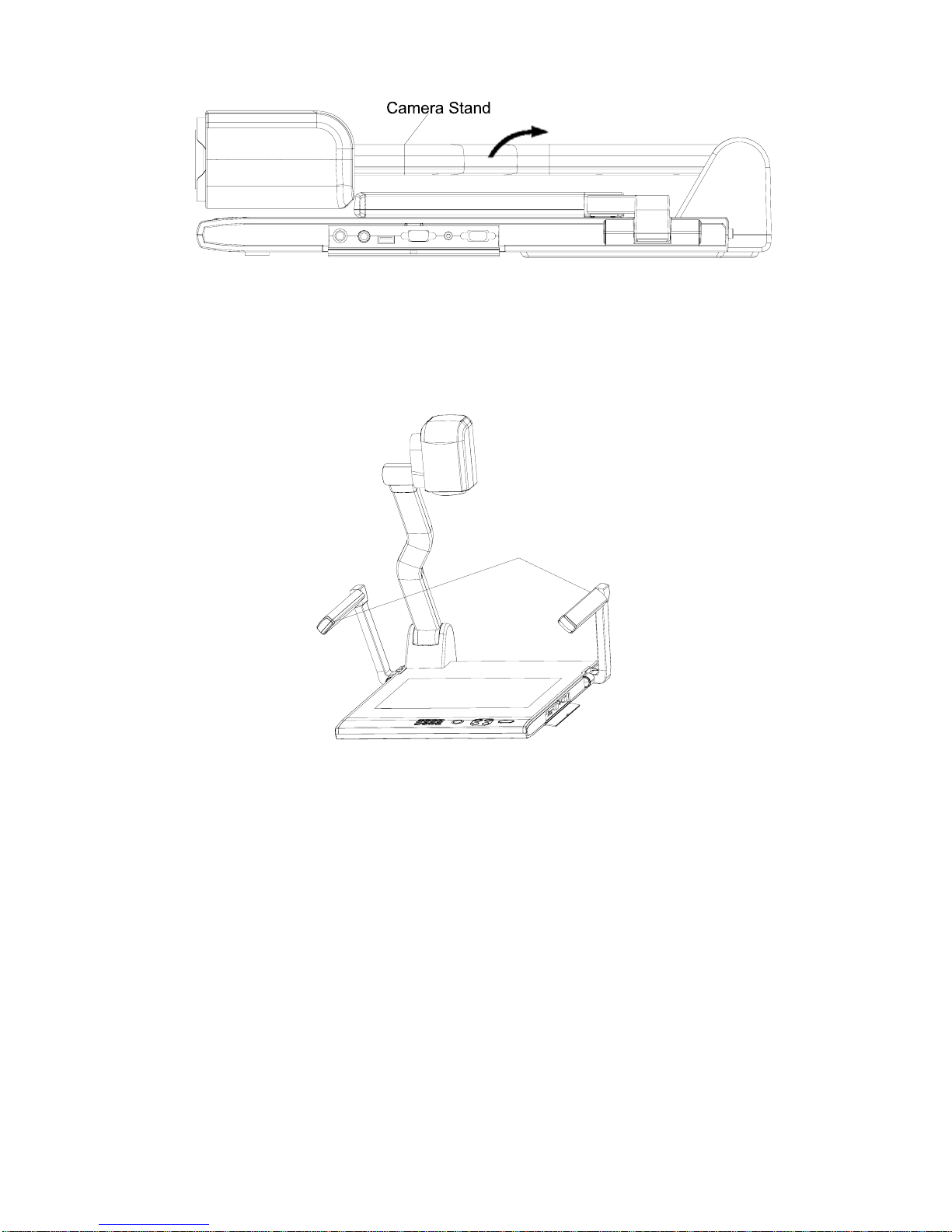
FOLDING THE UNIT
1. Fold the right arm light down first onto the base, then the left arm
down. Rotate the camera head clockwise until the camera head is
parallel to the camera stand.
2. Carefully Fold the camera stand down to the front panel.
Cautions:
a. Don’t lay the unit down flat.
b. Don’t try to stand it on its rear or sides.
18
Page 19

c. Don’t try to pick up this unit by pulling the camera stand.
SPECIFICATIONS
Color system NTSC or PAL system
Pickup device
1/4″professional CCD
Resolution XGA (1024 x 768), SVGA(800 x 600)
Total Pixels 470,000
RGB Output Pixels 780,000
16 x optical zoom, 8 x digital zoom
Lens
F=1.6~3.7mm / f=3.9~85.8 mm
Focus/Iris Auto/manual selectable
White balance Auto
Image split Yes
Negative/positive
conversion
Yes
Black/white and color
selection
Yes
Image Freeze Yes
Mirror Yes
Arm light: 1.5 W LED lamps x 2
Lights
Back light: 4 W LED lamps
NOT THIS WAY
19
Page 20

MIC: Mini jack 1
PC Audio: Mini jack 2
Input connectors
RGB: DB15FLC 2
RGB DB15FLC 2
C-Video: RCA jack 1
S-Video: 4 pin mini Din 1
Output connectors
Audio: Mini jack 1
Operating system Windows 2000/XP
USB connector 30 frames/sec
RS-232 connector 9-pin, D-Sub, male/6-pin PS/2
USB port USB 2.0
Power requirements 12V/4A external AC adapter
Folded: 20.0″ x 16.1″ x 4.7″
Setup: 20.0″ x 20.9″ x 22.4″
Dimension (W x D x H)
Packing: 25.6″ x 21.3″ x 9.1″
Weight
N.W: 5.5Kg (12.1lbs)
G.W: 9.5Kg (20.9 lbs)
Accessory
AC power cord
RGB cable
Audio/Video cable
S-Video cable
Computer RS232 cable (9-pin to 9-pin)
USB cable
Audio convert cable
AC adapter
User’s manual
Quick Start-up guide
Software CD
Infrared remote control
Warranty card
* Design and specifications are subject to change without notice.
20
Page 21

TECHNICAL SUPPORT
How to Reach QOMO:
By Phone
Call us at 1-866-990QOMO. Our expert personnel provide technical
assistance from 9:00AM through 5:00PM Eastern Standard Time,
Monday through Friday. Please gather the following information
before calling:
- Product model name(s) and numbers
- Product serial number(s)
- Detailed and specific questions
Online
Technical support is also available online at QOMO’s web site at
www.qomo.com, you can enter your questions and concerns
through our online form. Or you can email us at info@qomo.com.
Copyrights © 2004 QOMO Hitevision, LLC. All Rights Reserved.
21
 Loading...